EP2199553A1 - Failure detection apparatus for exhaust gas purifying filter - Google Patents
Failure detection apparatus for exhaust gas purifying filter Download PDFInfo
- Publication number
- EP2199553A1 EP2199553A1 EP09176901A EP09176901A EP2199553A1 EP 2199553 A1 EP2199553 A1 EP 2199553A1 EP 09176901 A EP09176901 A EP 09176901A EP 09176901 A EP09176901 A EP 09176901A EP 2199553 A1 EP2199553 A1 EP 2199553A1
- Authority
- EP
- European Patent Office
- Prior art keywords
- operating state
- electrode unit
- sampling process
- exhaust gas
- failure
- Prior art date
- Legal status (The legal status is an assumption and is not a legal conclusion. Google has not performed a legal analysis and makes no representation as to the accuracy of the status listed.)
- Granted
Links
Images




Classifications
-
- F—MECHANICAL ENGINEERING; LIGHTING; HEATING; WEAPONS; BLASTING
- F01—MACHINES OR ENGINES IN GENERAL; ENGINE PLANTS IN GENERAL; STEAM ENGINES
- F01N—GAS-FLOW SILENCERS OR EXHAUST APPARATUS FOR MACHINES OR ENGINES IN GENERAL; GAS-FLOW SILENCERS OR EXHAUST APPARATUS FOR INTERNAL-COMBUSTION ENGINES
- F01N11/00—Monitoring or diagnostic devices for exhaust-gas treatment apparatus
-
- F—MECHANICAL ENGINEERING; LIGHTING; HEATING; WEAPONS; BLASTING
- F01—MACHINES OR ENGINES IN GENERAL; ENGINE PLANTS IN GENERAL; STEAM ENGINES
- F01N—GAS-FLOW SILENCERS OR EXHAUST APPARATUS FOR MACHINES OR ENGINES IN GENERAL; GAS-FLOW SILENCERS OR EXHAUST APPARATUS FOR INTERNAL-COMBUSTION ENGINES
- F01N3/00—Exhaust or silencing apparatus having means for purifying, rendering innocuous, or otherwise treating exhaust
- F01N3/02—Exhaust or silencing apparatus having means for purifying, rendering innocuous, or otherwise treating exhaust for cooling, or for removing solid constituents of, exhaust
- F01N3/021—Exhaust or silencing apparatus having means for purifying, rendering innocuous, or otherwise treating exhaust for cooling, or for removing solid constituents of, exhaust by means of filters
-
- G—PHYSICS
- G01—MEASURING; TESTING
- G01N—INVESTIGATING OR ANALYSING MATERIALS BY DETERMINING THEIR CHEMICAL OR PHYSICAL PROPERTIES
- G01N15/00—Investigating characteristics of particles; Investigating permeability, pore-volume or surface-area of porous materials
- G01N15/06—Investigating concentration of particle suspensions
- G01N15/0606—Investigating concentration of particle suspensions by collecting particles on a support
-
- G—PHYSICS
- G01—MEASURING; TESTING
- G01N—INVESTIGATING OR ANALYSING MATERIALS BY DETERMINING THEIR CHEMICAL OR PHYSICAL PROPERTIES
- G01N15/00—Investigating characteristics of particles; Investigating permeability, pore-volume or surface-area of porous materials
- G01N15/06—Investigating concentration of particle suspensions
- G01N15/0656—Investigating concentration of particle suspensions using electric, e.g. electrostatic methods or magnetic methods
-
- F—MECHANICAL ENGINEERING; LIGHTING; HEATING; WEAPONS; BLASTING
- F01—MACHINES OR ENGINES IN GENERAL; ENGINE PLANTS IN GENERAL; STEAM ENGINES
- F01N—GAS-FLOW SILENCERS OR EXHAUST APPARATUS FOR MACHINES OR ENGINES IN GENERAL; GAS-FLOW SILENCERS OR EXHAUST APPARATUS FOR INTERNAL-COMBUSTION ENGINES
- F01N2550/00—Monitoring or diagnosing the deterioration of exhaust systems
- F01N2550/04—Filtering activity of particulate filters
-
- F—MECHANICAL ENGINEERING; LIGHTING; HEATING; WEAPONS; BLASTING
- F01—MACHINES OR ENGINES IN GENERAL; ENGINE PLANTS IN GENERAL; STEAM ENGINES
- F01N—GAS-FLOW SILENCERS OR EXHAUST APPARATUS FOR MACHINES OR ENGINES IN GENERAL; GAS-FLOW SILENCERS OR EXHAUST APPARATUS FOR INTERNAL-COMBUSTION ENGINES
- F01N2560/00—Exhaust systems with means for detecting or measuring exhaust gas components or characteristics
- F01N2560/05—Exhaust systems with means for detecting or measuring exhaust gas components or characteristics the means being a particulate sensor
-
- Y—GENERAL TAGGING OF NEW TECHNOLOGICAL DEVELOPMENTS; GENERAL TAGGING OF CROSS-SECTIONAL TECHNOLOGIES SPANNING OVER SEVERAL SECTIONS OF THE IPC; TECHNICAL SUBJECTS COVERED BY FORMER USPC CROSS-REFERENCE ART COLLECTIONS [XRACs] AND DIGESTS
- Y02—TECHNOLOGIES OR APPLICATIONS FOR MITIGATION OR ADAPTATION AGAINST CLIMATE CHANGE
- Y02T—CLIMATE CHANGE MITIGATION TECHNOLOGIES RELATED TO TRANSPORTATION
- Y02T10/00—Road transport of goods or passengers
- Y02T10/10—Internal combustion engine [ICE] based vehicles
- Y02T10/12—Improving ICE efficiencies
-
- Y—GENERAL TAGGING OF NEW TECHNOLOGICAL DEVELOPMENTS; GENERAL TAGGING OF CROSS-SECTIONAL TECHNOLOGIES SPANNING OVER SEVERAL SECTIONS OF THE IPC; TECHNICAL SUBJECTS COVERED BY FORMER USPC CROSS-REFERENCE ART COLLECTIONS [XRACs] AND DIGESTS
- Y02—TECHNOLOGIES OR APPLICATIONS FOR MITIGATION OR ADAPTATION AGAINST CLIMATE CHANGE
- Y02T—CLIMATE CHANGE MITIGATION TECHNOLOGIES RELATED TO TRANSPORTATION
- Y02T10/00—Road transport of goods or passengers
- Y02T10/10—Internal combustion engine [ICE] based vehicles
- Y02T10/40—Engine management systems
Definitions
- the present invention relates to failure detection apparatus for an exhaust gas purifying filter.
- the present invention relates to failure detection apparatus for an exhaust gas purifying filter that uses an electrostatic dust collection type of particulate matter sensor.
- Japanese Unexamined Patent Application Publication Nos. 2008-115765 and 2007-315275 disclose failure detection apparatuses provided with a particulate matter sensor detecting particulate matter in exhaust gas, which is provided at the downstream side of the exhaust gas purifying filter, to detect the failure of the exhaust gas purifying filter based on outputs from this sensor.
- Japanese Unexamined Patent Application Publication No. 2008-115765 discloses that an electrical discharge sensor generating a discharge voltage corresponding to the concentration of particulate matter in exhaust gas is used as a particulate matter sensor.
- Japanese Unexamined Patent Application Publication No. 2007-132290 discloses a failure detection apparatus provided with particulate matter sensors upstream and downstream of the exhaust gas purifying filter, respectively.
- This failure detection apparatus calculates the ratio of the amount of particulate matter flowing in the exhaust gas purifying filter to the amount of particulate matter flowing out from the exhaust gas purifying filter based on the output from each of the sensors, and then compares the calculated ratio with that when the filter is in a normal state, thereby detecting the failure of the exhaust gas purifying filter.
- the particulate matter sensor used for the above-mentioned failure detection apparatus is demanded not only to be capable of high accuracy detection, but also to have excellent durability for mounting in an exhaust gas path.
- it is demanded to have a simple configuration to be equipped in a vehicle.
- an electrostatic dust collection type of particulate matter sensor has been proposed as a particulate matter sensor that satisfies such demands (refer to Japanese Unexamined Patent Application Publication No. 2008-139294 ).
- an electrode unit composed of a pair of electrode plates is provided in an exhaust pipe, and particulate matter is thus deposited on this electrode unit by applying a predetermined voltage to the electrode unit. Then, the concentration of particulate matter in the exhaust gas in the exhaust pipe can be detected by measuring an electrical characteristic such as the capacitance of the electrode unit on which particulate matter is deposited.
- the detection of the concentration of particulate matter by the above-mentioned electrostatic dust collection type of particulate matter sensor is performed in two steps: a step of performing a sampling process of depositing particulate matter on the electrode unit, and a step of performing a measurement process of measuring the electrical characteristic of the electrode unit after this sampling process, it lacks readiness.
- the failure detection accuracy may be lowered. Specifically, since the operating state of the internal combustion engine changes in accordance with the driver's operation and the like, using an electrostatic dust collection type of particulate matter sensor makes a difference between the operating state in the performance of the sampling process and the operating state in the performance of the measurement process, failure may not be correctly detected.
- the present invention was made by taking the above such issues into account, and an object thereof is to provide a failure detection apparatus for an exhaust gas purifying filter that uses an electrostatic dust collection type of particulate matter sensor while being capable of detecting failure with high-accuracy.
- the present invention provides a failure detection apparatus for an exhaust gas purifying filter (3) that is provided in an exhaust gas path (4) of an internal combustion engine (1), and that collects particulate matter contained in exhaust gas emitted from the internal combustion engine.
- the failure detection apparatus includes: an operating state detection means (5, 7, 8) for detecting an operating state of the internal combustion engine; an electrode unit (24) provided downstream of the exhaust gas purifying filter in the exhaust gas path; a particulate matter detection means (5,21) for performing a sampling process of causing particulate matter to deposit on the electrode unit by applying a predetermined voltage to the electrode unit, and then performing a measurement process of measuring a predetermined electrical characteristic of the electrode unit; and a failure detection means (5) for detecting failure of the exhaust gas purifying filter based on an operating state parameter (N, W, N MEAS_AVE , W MEAS_AVE ) indicating the operating state of the internal combustion engine while performing the sampling process and a measured value ( ⁇ C) measured by performing the measurement process.
- an operating state detection means 5, 7, 8) for detecting an operating state of the internal combustion engine
- an electrode unit (24) provided downstream of the exhaust gas purifying filter in the exhaust gas path
- a particulate matter detection means for performing a sampling process of causing particulate matter
- the sampling process of causing particulate matter to deposit on the electrode unit by applying a predetermined voltage to the electrode unit is performed, and then the measurement process of measuring a predetermined electrical characteristic of this electrode unit is performed.
- failure of the exhaust gas purifying filter is detected based on a measured value measured by this measurement process and the operating state parameter.
- an operating state parameter indicating the operating status of the internal combustion engine while performing the sampling process it is possible to detect failure of the exhaust gas purifying filter with high accuracy even if the operating state while performing the sampling process differs from that while performing the measurement process.
- the failure detection means sets a first threshold value (C TH ) in accordance with the operating state parameter, and then compares the first threshold value with the measured value (N,W,N MEAS_AVE , W MEAS_AVE ) measured by performing the measurement process to detect failure of the exhaust gas purifying filter.
- the first threshold value is set in accordance with the operating state parameter while performing the sampling process, and then failure of the exhaust gas purifying filter is detected by comparing this first threshold value with the measured value. For example, by using the control map and the like that are set based on preliminarily performed experimentation when the first threshold value is set from the operating state parameter, the failure detection accuracy of the exhaust gas purifying filter can be further improved.
- the electrical characteristic is a variation amount in capacitance ( ⁇ C) from before and after performing the sampling process.
- the variation amount in capacitance from before and after performing the sampling process is measured as a predetermined electrical characteristic of the electrode unit in the measurement process.
- the capacitance of the electrode unit significantly changes when particulate matter is deposited on the electrode unit.
- the concentration of particulate matter contained in exhaust gas downstream of the exhaust gas purifying filter can be detected accurately. Therefore, the failure detection accuracy of the exhaust gas purifying filter can be further improved.
- the operating state parameter is a mean value (N MEAS_AVE , W MEAS_AVE ) of a detection value detected by the operating state detection means while performing the sampling process.
- a mean value of the detection value which is detected by the operating state detection means while performing the sampling process, is used as the operating state parameter.
- the operating state of the internal combustion engine can be more accurately reflected in the operating state parameter. Therefore, by detecting the failure of the exhaust gas purifying filter with such an operating state parameter, the failure detection accuracy of the exhaust gas purifying filter can be further improved.
- the failure detection apparatus further includes a perform sampling determination means (5) for determining whether or not the detection value detected by the operating state detection means before performing the sampling process is within a predetermined first determination range ([N MIN, N MAX ], [M MIN, W MAX ]) over a predetermined first determination time (T PRE ), in which the sampling process is performed only in a case where the detection value is determined to be within the first determination range over the first determination time.
- a perform sampling determination means (5) for determining whether or not the detection value detected by the operating state detection means before performing the sampling process is within a predetermined first determination range ([N MIN, N MAX ], [M MIN, W MAX ]) over a predetermined first determination time (T PRE ), in which the sampling process is performed only in a case where the detection value is determined to be within the first determination range over the first determination time.
- the sampling process is performed only in a case where the detection value detected by the operating state detection means before performing the sampling process is within the first determination range over the first determination time, or only in a case where the operating state of the internal combustion engine is stable.
- the concentration of particulate matter in exhaust gas cannot be accurately reflected in the measured value measured in the measurement process.
- the failure detection apparatus further includes a perform measurement determination means (5) for determining whether or not the detection value detected by the operating state detection means while performing the sampling process is within a predetermined second determination range ([N MIN ,N MAX ], [W MIN, W MAX ]) over a predetermined second determination time (T MEAS ), in which the sampling process is performed only in a case where the detection value is determined to be within the second determination range over the second determination time.
- a perform measurement determination means (5) for determining whether or not the detection value detected by the operating state detection means while performing the sampling process is within a predetermined second determination range ([N MIN ,N MAX ], [W MIN, W MAX ]) over a predetermined second determination time (T MEAS ), in which the sampling process is performed only in a case where the detection value is determined to be within the second determination range over the second determination time.
- the measurement process is performed only in a case where the detection value detected by the operating state detection means while performing the sampling process is within the second determination range over the second determination time, or only in a case where the sampling process has been performed in a state in which the operating state of the internal combustion engine was stable. Therefore, the failure detection accuracy of the exhaust gas purifying filter can be further improved.
- the failure detection apparatus further includes: a test particulate matter detection means (5,21) for performing a test sampling process of causing particulate matter to deposit on the electrode unit by applying a predetermined voltage to the electrode unit, and then performing a test measurement process of measuring a predetermined electrical characteristic of the electrode unit; a determination means (5) for determining whether or not to perform the sampling process and the measurement process, by comparing a predetermined second threshold value (C THT ) with the measured value ( ⁇ C T ) measured by performing the test measurement process; and a prevention means (5) for preventing the sampling process and the measurement process from being performed in a case where the determination means determines that the sampling process and the measurement process are not to be performed.
- a test particulate matter detection means for performing a test sampling process of causing particulate matter to deposit on the electrode unit by applying a predetermined voltage to the electrode unit, and then performing a test measurement process of measuring a predetermined electrical characteristic of the electrode unit
- a determination means (5) for determining whether or not to perform the sampling
- the test sampling process and the test measurement process are performed, and then it is determined whether or not to perform the above-mentioned sampling process and the above-mentioned measurement process by comparing the second threshold value with the measured value measured by performing this test measurement process. In a case where it is determined that the sampling process and the measurement process are not to be performed, the sampling process and the measurement process are prevented from being performed.
- the sampling process and the measurement process are performed only in a case where the operating state of the internal combustion engine is stable. Therefore, in a case where the operating state substantially changes while performing the sampling process, for example, it is necessary to temporarily interrupt the sampling process so as not to be performed consecutively, remove particulate matter deposited on the electrode unit, this electrode unit is regenerated, and then repeat performing the sampling process once more after regenerating this sensor electrode unit.
- Such regeneration of the electrode unit is conducted, for example, by heating the electrode unit with heaters over a predetermined time to combust particulate matter. That is, in a case where the operating state of the internal combustion engine is unstable, the electrode unit is regenerated more frequently, which causes the detection for failure of the exhaust gas purifying filter to be performed less frequently.
- the test sampling process and the test measurement process are performed provisionally, and then it is determined whether or not to perform the sampling process and the measurement process for detecting failure based on these results.
- the sampling process and the measurement process can be performed less frequently, and the electrode unit can be regenerated less frequently. As a result, it is possible to improve the frequency at which detection for failure of the exhaust gas purifying filter is performed.
- the determination means compares the second threshold value (C THT ) with the measured value ( ⁇ C T ) measured by performing the test measurement process, and determines that the sampling process and the measurement process are not to be performed in a case where the measured value is smaller than the second threshold value.
- the measured value measured by performing the test measurement process is compared with the second threshold value, and in a case where the measured value is smaller than the second threshold value, the sampling process and the measurement process are prevented from being performed.
- setting the second threshold value to an extremely small value can prevent the sampling process and the measurement process for detecting the failure of the exhaust gas purifying filter from being performed, even though the exhaust gas purifying filter is normal. As a result, it is possible to improve the frequency at which detection for failure of the exhaust gas purifying filter is performed.
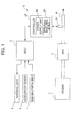
- FIG. 1 is a diagram illustrating the structure of an internal combustion engine and a control unit thereof including a failure detection apparatus for an exhaust gas purifying filter according to the present embodiment of the present invention.
- An internal combustion engine 1 (hereinafter simply referred to as “engine”) is a diesel engine that directly injects fuel into each cylinder and a fuel injector (not shown) is provided in each cylinder. These fuel injectors are electrically connected with an electronic control unit 5 (hereinafter referred to as "ECU”) that controls a valve-opening time and a valve-closing time of the fuel injectors.
- ECU electronice control unit 5
- An exhaust pipe 4 in which exhaust gas from the engine 1 flows is provided with, in this order from the upstream side, a diesel particulate filter (hereinafter referred to as "DPF") 3 and a particulate matter (hereinafter referred to as "PM”) sensor 2 detecting PM, the principal component of which is carbon contained in exhaust gas.
- DPF diesel particulate filter
- PM particulate matter
- the DPF 3 is provided with filter walls of a porous media and, when exhaust gas passes through fine pores of this filter wall, PM contained in the exhaust gas is collected by being deposited on the surface of the filter wall and in the pores of the filter wall.
- porous media made of aluminum titanate, cordierite, and the like are used as a constituent material of the filter wall.
- the PM sensor 2 is a so-called electrostatic dust collection type of particulate matter sensor provided with a sensor electrode unit 24 provided at the downstream side of the DPF 3 along an exhaust gas pipe 4 and a controller 21 controlling this sensor electrode unit 24.
- FIGs. 2A and 2B are perspective views illustrating the structure of the sensor electrode unit 24. More specifically, FIG. 2A is a perspective view illustrating the structure of an electrode plate 25 of the sensor electrode unit 24, and FIG. 2B is a perspective view illustrating the structure of the sensor electrode unit 24 configured to including the two electrode plates 25, 25.
- the electrode plate 25 is provided with a substantially rectangular alumina substrate 251 and a tungsten conductive layer 252 formed on the surface of this alumina substrate 251.
- This tungsten conductive layer 252 is configured to including a conductive part formed in a substantially square shape at substantially the center part of the alumina substrate 251, and a conductive wire part extending from this conductive part to a first end side of the alumina substrate 251.
- a tungsten printed part 253 provided by being stacked on the conductive wire part of this tungsten conductive layer 252 is formed.
- the thickness of the alumina substrate 251 is about 1 mm, and the length on a side of the conductive part of the tungsten conductive layer 252 is about 10 mm.
- the sensor electrode unit 24 is configured by disposing plate-like spacers 26, 26 between a pair of electrode plates 25, 25 to be combined. These spacers 26, 26 are provided at both end sides of each electrode plate 25, and a cavity 27 in which PM is collected is, therefore, formed at the conductive part of the tungsten conductive layer 252 of each electrode plate 25.
- the heaters (not shown) are installed in a pair of electrode plates 25, 25 configuring this sensor electrode unit 24, respectively.
- a controller 21 of the PM sensor 2 is configured to including a power supply unit 22 supplying electric power to the sensor electrode unit 24 and impedance measuring equipment 23 detecting an electrical characteristic of the sensor electrode unit 24.
- the power supply unit 22 operates based on control signals transmitted from the ECU 5 to apply a predetermined voltage to the sensor electrode unit 24 over a predetermined time. Accordingly, PM contained in the exhaust gas is deposited in a cavity of the sensor electrode unit 24. In addition, by applying a current to the above-mentioned heaters provided in the sensor electrode unit 24, this power supply unit 22 can warm up this sensor electrode unit 24 and can combust deposited PM to regenerate the sensor electrode unit 24.
- the impedance measuring equipment 23 operates based on control signals transmitted from the ECU 5 to detect the capacitance of the sensor electrode unit 24 with an alternating current signal applied at a predetermined measured voltage over a predetermined measurement period, and outputs a detection signal substantially proportional to the capacitance value thus detected to the ECU 5.
- the ECU 5 is connected to a warning light 6, a crank angle position sensor 7, an accelerator sensor 8, and the like in addition to the above-mentioned PM sensor 2.
- the warning light 6 is provided in an instrument panel of a vehicle, and lights up based on a control signal transmitted from the ECU 5. In a case where it is determined that the DPF 3 has failed, the ECU 5 turns on this warning light 6, as described below. Thus, the fact that the DPF 3 has failed can be informed to the driver.
- the crank angle position sensor 7 detects the rotation angle of the crankshaft of the engine 1 and outputs a detection signal to the ECU 5.
- the accelerator sensor 8 detects the amount by which the accelerator pedal of a vehicle has been depressed, and outputs a detection signal to the ECU 5. Revolution speed N and fuel consumption amount W as the operating state parameters indicating the operating state of the engine 1 are calculated by the ECU 5 based on outputs from the crank angle position sensor 7 and the accelerator sensor 8.
- the ECU 5 is provided with an input circuit having functions such as shaping signal waveforms that are input from various kinds of sensors, correcting voltage levels to a predetermined level, and converting analog signal values into digital signal values, and a central processing unit (hereinafter referred to as "CPU"). Furthermore, the ECU 5 is provided with a memory circuit that stores various kinds of calculation programs to be executed by the CPU, calculation results, and the like, and an output circuit that outputs control signals to the controller 21 of the PM sensor 2, the warning light 6, the fuel injectors of the engine 1, etc.
- CPU central processing unit
- FIG. 3 is a flow chart illustrating the procedure of the DPF failure detection process. This DPF failure detection process is executed by the ECU 5 after the engine starts.
- Step S1 warm-up, regeneration, and calibration of the PM sensor are performed.
- Step S2 the capacitance of the sensor electrode unit is measured, and then recorded as an initial capacitance C I .
- Step S3 while a sampling process is being performed over a predetermined time, the operating state parameters (revolution speed N, fuel consumption amount W) while performing this sampling process are recorded. More specifically, in this sampling process, PM contained in the exhaust gas is caused to deposit in the cavity of the sensor electrode unit by applying a voltage to the sensor electrode unit over a predetermined time.
- Step S5 a failure determination value C TH is set in accordance with the recorded operating state parameters (revolution speed N, fuel consumption amount W). More specifically, in Step S5, the failure determination value C TH is set based on a control map as shown in the following table, in which the failure determination value C TH is set in relation to each operating state parameter (revolution speed N, fuel consumption amount W).
- Table 1 REVOLUTION SPEED N N 1 N 2 ⁇ FUEL CONSUMPTION AMOUNT W W 1 C 11 C 12 ⁇ W 2 C 21 C 22 ⁇ ⁇ ⁇ ⁇ ⁇
- Step S6 it is determined whether or not the variation amount of capacitance ⁇ C thus measured is smaller than the failure determination value C TH . In a case where this determination is "YES”, it is determined that the DPF is in a normal state, and the process proceeds to Step S7. In a case where this determination is "NO”, it is determined that the DPF is in a failed state, and the process proceeds to Step S8.
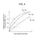
- FIG. 4 is a diagram illustrating the relationship between the variation amount of capacitance ⁇ C and the PM concentration. More specifically, FIG. 4 is a diagram obtained by running the engine at each of the operating states (N 1 ,W 1 ), (N 1 ,W 2 ), and (N 2 ,W 1 ), while changing the PM concentration downstream of the DPF by intentionally damaging the DPF, and measuring the variation amount of capacitance ⁇ C at each of the PM concentrations.
- the above-mentioned control map is set by selecting the points at which it is determined that the DPF has failed, from the measurement result in relation to each of the operating states (N 1 ,W 1 ), (N 1 ,W 2 ), and (N 2 ,W 1 ) shown in FIG. 4 , and then defining the respective variation amounts of capacitance ⁇ C at these points as failure determination values C 11 , C 12 , and C 21 .
- a control map is made in order to set a failure determination value C TH in accordance with the recorded operating state parameters (revolution speed N, fuel consumption amount W).
- Step S7 the sensor electrode unit is regenerated, and then the process returns to Step S2.
- Step S8 the warning light is turned on in response to the determination that the DPF is in a failed state, and then the process proceeds to Step S7.
- FIG. 7 is a flow chart illustrating the procedure of the DPF failure detection process according to the present embodiment. As shown in FIG. 7 , the present embodiment differs from the second embodiment in the point that the test detection process is performed in Step S32, and the main detection process is performed in Step S35 only in a case where performing the main detection process is determined to be required.
- Step S31 warm-up, regeneration, and calibration of the PM sensor are performed.
- Step S32 the test detection process described in detail below with reference to FIG. 8 is performed.
- Step S33 it is determined whether or not a first determination flag F 1ST_CHK is "1.” In a case where this determination is "YES”, the process proceeds to Step S34, and in a case where this determination is "NO", the process proceeds to Step S32.
- the first determination flag F 1ST_CHK is a flag indicating that performing the main detection process is required, and is set to "1" in Step S49 of the test detection process described below with reference to FIG. 8 .
- this first determination flag F 1ST_CHK is set to "0" immediately after performing this DPF failure detection process.
- Step S34 the sensor electrode unit is regenerated.
- Step S35 the main detection process described in detail below with reference to FIG. 9 is performed.
- Step S36 it is determined whether or not a second determination flag F 2ND_CHK is "1." In a case where this determination is "YES”, the process proceeds to Step S37, and in a case where this determination is "NO", the process proceeds to Step S38.
- the second determination flag F 2ND_CHK is a flag indicating that the DPF is in a failed state, and is set to "1" in Step S61 of the main detection process illustrated in FIG. 9 described later. This second determination flag F 2ND_CHK is set to "0" immediately after performing this DPF failure detection process.
- Step S37 the warning light is turned on in response to the determination that the DPF is in a failed state, and then the process proceeds to Step S38.
- Step S38 the sensor electrode unit is regenerated, and then the process returns to Step S35.
- FIG. 8 is a flow chart illustrating the procedure of the test detection process.
- Step S41 a test count variable I 1ST_REG is incremented by "1."
- This test count variable I 1ST_REG represents the number of times that the test detection process is performed consecutively without regenerating the sensor electrode unit.
- Step S42 it is determined whether or not a predetermined upper limit value of the consecutive times N 1ST_REG is equal to the test count variable I 1ST_REG . In a case where this determination is "YES”, the process proceeds to Step S43, and in a case where this determination is "NO”, the process proceeds to Step S44.
- Step S43 a test count variable I 1ST_REG is reset to "0" after regenerating the sensor electrode unit.
- Step S44 the capacitance of the sensor electrode unit is measured, and then recorded as an initial capacitance C IT .
- Step S45 the test sampling process is performed over a predetermined time. More specifically, in this test sampling process, PM contained in the exhaust gas is caused to deposit in the cavity of the sensor electrode unit by applying a voltage to the sensor electrode unit over a predetermined time.
- Step S47 it is determined whether or not the measured variation amount ⁇ C T of capacitance is smaller than a predetermined execution determination value C THT .
- the execution determination value C THT is a threshold value that is set to determine whether or not to perform the main detection process, and is set to an extremely small value.
- Step S48 the first determination flag F 1ST_CHK is set to "0" to prevent the main detection process from being performed.
- Step S49 the first determination flag F 1ST_CHK is set to "1" to allow the main detection process to be performed.
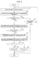
- FIG. 9 is a flow chart illustrating the procedure of the main failure detection process.
- Steps S51 to S58 are the same as Steps S12 to S19 of the flow chart shown in FIG. 5 , and a detailed explanation is, therefore, omitted.
- Step S59 it is determined whether or not the variation amount of capacitance ⁇ C thus measured is smaller than the failure determination value C TH . In a case where this determination is "YES”, it is determined that the DPF is in a normal state, and then the process proceeds to Step S60 in which the second determination flag F 2ND_CHK is set to "0.” In a case where this determination is "NO”, it is determined that the DPF is in a failed state, and then the process proceeds to Step S61 in which set the second determination flag F 2ND_CHK is set to "1.”
- the following effects can be attained in addition to the above-mentioned effects (1) to (6).
- the means involved in performing Steps S58 and S59 in FIG. 9 configure the failure detection means
- the means involved in performing Steps S55 and S57 in FIG. 9 configure the particulate matter detection means
- the means involved in performing Step S53 in FIG. 9 configure the perform sampling determination means
- the means involved in performing Step S56 in FIG. 9 configure the perform measurement determination means
- the means involved in performing Steps S45 and S46 in FIG. 8 configure the test particulate matter detection means
- the means involved in performing Step S47 in FIG. 8 configure the determination means
- the means involved in performing Step S48 in FIG. 8 configure the prevention means.
- the revolution speed N and the fuel consumption amount W are used as the operating state parameters indicating the operating state of the engine; however, the type or the number of operating state parameters is not limited thereto. Any operating state parameters may be used to obtain the emission amount of PM exhausted from the engine, such as the amount of intake air.
- a failure detection apparatus for an exhaust gas purifying filter uses an electrostatic dust collection type of particulate matter sensor, while being capable of high-accuracy detection of failure.
- the failure detection apparatus for a DPF performs a sampling process (S3) that causes PM to deposit on a sensor electrode unit by applying a predetermined voltage to the sensor electrode unit, and then performs the measurement process (S4) to measure the variation amount of capacitance ⁇ C of the sensor electrode unit.
- the failure detection apparatus for a DPF records operating state parameters (revolution speed N, fuel consumption amount W) in the performance of this sampling process, and then detects DPF failure based on these operating state parameters (revolution speed N, fuel consumption amount W) and the variation amount of capacitance ⁇ C.
Landscapes
- Chemical & Material Sciences (AREA)
- Engineering & Computer Science (AREA)
- Health & Medical Sciences (AREA)
- Life Sciences & Earth Sciences (AREA)
- Mechanical Engineering (AREA)
- General Engineering & Computer Science (AREA)
- Dispersion Chemistry (AREA)
- Physics & Mathematics (AREA)
- Pathology (AREA)
- Combustion & Propulsion (AREA)
- Analytical Chemistry (AREA)
- Biochemistry (AREA)
- General Health & Medical Sciences (AREA)
- General Physics & Mathematics (AREA)
- Immunology (AREA)
- Chemical Kinetics & Catalysis (AREA)
- Processes For Solid Components From Exhaust (AREA)
- Investigating Or Analyzing Materials By The Use Of Electric Means (AREA)
Abstract
Description
- This application is based on and claims the benefit of priority from Japanese Patent Application No.
2008-325978, filed on 22 December 2008 - The present invention relates to failure detection apparatus for an exhaust gas purifying filter. In particular, the present invention relates to failure detection apparatus for an exhaust gas purifying filter that uses an electrostatic dust collection type of particulate matter sensor.
- Technology that provides an exhaust gas purifying filter that collects particulate matter contained in exhaust gas, in an exhaust gas path of an internal combustion engine, has been widely used to decrease the emission amount of particulate matter. In addition, in a vehicle provided with an exhaust gas purifying filter, an apparatus for detecting the failure of the exhaust gas purifying filter is also provided. As this failure detection apparatus for an exhaust gas purifying filter, the below-mentioned apparatus has been suggested thus far.
- For example, Japanese Unexamined Patent Application Publication Nos.
2008-115765 2007-315275 2008-115765 - In addition, Japanese Unexamined Patent Application Publication No.
2007-132290 - Incidentally, the particulate matter sensor used for the above-mentioned failure detection apparatus is demanded not only to be capable of high accuracy detection, but also to have excellent durability for mounting in an exhaust gas path. In addition, it is demanded to have a simple configuration to be equipped in a vehicle. For example, an electrostatic dust collection type of particulate matter sensor has been proposed as a particulate matter sensor that satisfies such demands (refer to Japanese Unexamined Patent Application Publication No.
2008-139294 - In the electrostatic dust collection type of particulate matter sensor, an electrode unit composed of a pair of electrode plates is provided in an exhaust pipe, and particulate matter is thus deposited on this electrode unit by applying a predetermined voltage to the electrode unit. Then, the concentration of particulate matter in the exhaust gas in the exhaust pipe can be detected by measuring an electrical characteristic such as the capacitance of the electrode unit on which particulate matter is deposited.
- However, since the detection of the concentration of particulate matter by the above-mentioned electrostatic dust collection type of particulate matter sensor is performed in two steps: a step of performing a sampling process of depositing particulate matter on the electrode unit, and a step of performing a measurement process of measuring the electrical characteristic of the electrode unit after this sampling process, it lacks readiness.
- Therefore, when such an electrostatic dust collection type of particulate matter sensor is used in a failure detection apparatus for an exhaust gas purifying filter, the failure detection accuracy may be lowered. Specifically, since the operating state of the internal combustion engine changes in accordance with the driver's operation and the like, using an electrostatic dust collection type of particulate matter sensor makes a difference between the operating state in the performance of the sampling process and the operating state in the performance of the measurement process, failure may not be correctly detected.
- The present invention was made by taking the above such issues into account, and an object thereof is to provide a failure detection apparatus for an exhaust gas purifying filter that uses an electrostatic dust collection type of particulate matter sensor while being capable of detecting failure with high-accuracy.
- In order to achieve the above-mentioned object, the present invention provides a failure detection apparatus for an exhaust gas purifying filter (3) that is provided in an exhaust gas path (4) of an internal combustion engine (1), and that collects particulate matter contained in exhaust gas emitted from the internal combustion engine. The failure detection apparatus includes: an operating state detection means (5, 7, 8) for detecting an operating state of the internal combustion engine; an electrode unit (24) provided downstream of the exhaust gas purifying filter in the exhaust gas path; a particulate matter detection means (5,21) for performing a sampling process of causing particulate matter to deposit on the electrode unit by applying a predetermined voltage to the electrode unit, and then performing a measurement process of measuring a predetermined electrical characteristic of the electrode unit; and a failure detection means (5) for detecting failure of the exhaust gas purifying filter based on an operating state parameter (N, W, NMEAS_AVE, WMEAS_AVE) indicating the operating state of the internal combustion engine while performing the sampling process and a measured value (ΔC) measured by performing the measurement process.
- According to the present invention, the sampling process of causing particulate matter to deposit on the electrode unit by applying a predetermined voltage to the electrode unit is performed, and then the measurement process of measuring a predetermined electrical characteristic of this electrode unit is performed. In addition, failure of the exhaust gas purifying filter is detected based on a measured value measured by this measurement process and the operating state parameter. In particular, by using an operating state parameter indicating the operating status of the internal combustion engine while performing the sampling process, it is possible to detect failure of the exhaust gas purifying filter with high accuracy even if the operating state while performing the sampling process differs from that while performing the measurement process.
- In this case, it is preferable that the failure detection means sets a first threshold value (CTH) in accordance with the operating state parameter, and then compares the first threshold value with the measured value (N,W,NMEAS_AVE, WMEAS_AVE) measured by performing the measurement process to detect failure of the exhaust gas purifying filter.
- According to the present invention, the first threshold value is set in accordance with the operating state parameter while performing the sampling process, and then failure of the exhaust gas purifying filter is detected by comparing this first threshold value with the measured value. For example, by using the control map and the like that are set based on preliminarily performed experimentation when the first threshold value is set from the operating state parameter, the failure detection accuracy of the exhaust gas purifying filter can be further improved.
- In this case, it is preferable that the electrical characteristic is a variation amount in capacitance (ΔC) from before and after performing the sampling process.
- According to the present invention, the variation amount in capacitance from before and after performing the sampling process is measured as a predetermined electrical characteristic of the electrode unit in the measurement process. The capacitance of the electrode unit significantly changes when particulate matter is deposited on the electrode unit. According to the present invention, by measuring such a variation amount of capacitance of the electrode unit, the concentration of particulate matter contained in exhaust gas downstream of the exhaust gas purifying filter can be detected accurately. Therefore, the failure detection accuracy of the exhaust gas purifying filter can be further improved.
- In this case, it is preferable that the operating state parameter is a mean value (NMEAS_AVE, WMEAS_AVE) of a detection value detected by the operating state detection means while performing the sampling process.
- According to the present invention, a mean value of the detection value, which is detected by the operating state detection means while performing the sampling process, is used as the operating state parameter. Thus, while performing the sampling process, or while causing particulate matter to deposit on the electrode unit, the operating state of the internal combustion engine can be more accurately reflected in the operating state parameter. Therefore, by detecting the failure of the exhaust gas purifying filter with such an operating state parameter, the failure detection accuracy of the exhaust gas purifying filter can be further improved.
- In this case, it is preferable that the failure detection apparatus further includes a perform sampling determination means (5) for determining whether or not the detection value detected by the operating state detection means before performing the sampling process is within a predetermined first determination range ([NMIN,NMAX], [MMIN,WMAX]) over a predetermined first determination time (TPRE), in which the sampling process is performed only in a case where the detection value is determined to be within the first determination range over the first determination time.
- According to the present invention, the sampling process is performed only in a case where the detection value detected by the operating state detection means before performing the sampling process is within the first determination range over the first determination time, or only in a case where the operating state of the internal combustion engine is stable. For example, in a case where the operating state of the internal combustion engine substantially changes while performing the sampling process, or while causing particulate matter to deposit on the electrode unit, the concentration of particulate matter in exhaust gas cannot be accurately reflected in the measured value measured in the measurement process. According to the present invention, by performing the sampling process only in a case where the operating state is stable as described above, the failure detection accuracy of the exhaust gas purifying filter can be further improved.
- In this case, it is preferable that the failure detection apparatus further includes a perform measurement determination means (5) for determining whether or not the detection value detected by the operating state detection means while performing the sampling process is within a predetermined second determination range ([NMIN,NMAX], [WMIN,WMAX]) over a predetermined second determination time (TMEAS), in which the sampling process is performed only in a case where the detection value is determined to be within the second determination range over the second determination time.
- According to the present invention, the measurement process is performed only in a case where the detection value detected by the operating state detection means while performing the sampling process is within the second determination range over the second determination time, or only in a case where the sampling process has been performed in a state in which the operating state of the internal combustion engine was stable. Therefore, the failure detection accuracy of the exhaust gas purifying filter can be further improved.
- In this case, it is preferable that the failure detection apparatus further includes: a test particulate matter detection means (5,21) for performing a test sampling process of causing particulate matter to deposit on the electrode unit by applying a predetermined voltage to the electrode unit, and then performing a test measurement process of measuring a predetermined electrical characteristic of the electrode unit; a determination means (5) for determining whether or not to perform the sampling process and the measurement process, by comparing a predetermined second threshold value (CTHT) with the measured value (ΔCT) measured by performing the test measurement process; and a prevention means (5) for preventing the sampling process and the measurement process from being performed in a case where the determination means determines that the sampling process and the measurement process are not to be performed.
- According to the present invention, the test sampling process and the test measurement process are performed, and then it is determined whether or not to perform the above-mentioned sampling process and the above-mentioned measurement process by comparing the second threshold value with the measured value measured by performing this test measurement process. In a case where it is determined that the sampling process and the measurement process are not to be performed, the sampling process and the measurement process are prevented from being performed.
- Incidentally, in the failure detection apparatus of the present invention, the sampling process and the measurement process are performed only in a case where the operating state of the internal combustion engine is stable. Therefore, in a case where the operating state substantially changes while performing the sampling process, for example, it is necessary to temporarily interrupt the sampling process so as not to be performed consecutively, remove particulate matter deposited on the electrode unit, this electrode unit is regenerated, and then repeat performing the sampling process once more after regenerating this sensor electrode unit. Such regeneration of the electrode unit is conducted, for example, by heating the electrode unit with heaters over a predetermined time to combust particulate matter. That is, in a case where the operating state of the internal combustion engine is unstable, the electrode unit is regenerated more frequently, which causes the detection for failure of the exhaust gas purifying filter to be performed less frequently.
- Thus, according to the present invention, by taking advantage of the fact that, when the exhaust gas purifying filter is normal, the amount of particulate matter deposited on the electrode unit extremely decreases regardless of the operating state of the internal combustion engine, the test sampling process and the test measurement process are performed provisionally, and then it is determined whether or not to perform the sampling process and the measurement process for detecting failure based on these results. Thus, in a state in which the exhaust gas purifying filter is in a normal state, the sampling process and the measurement process can be performed less frequently, and the electrode unit can be regenerated less frequently. As a result, it is possible to improve the frequency at which detection for failure of the exhaust gas purifying filter is performed.
- In this case, it is preferable that the determination means compares the second threshold value (CTHT) with the measured value (ΔCT) measured by performing the test measurement process, and determines that the sampling process and the measurement process are not to be performed in a case where the measured value is smaller than the second threshold value.
- According to the present invention, the measured value measured by performing the test measurement process is compared with the second threshold value, and in a case where the measured value is smaller than the second threshold value, the sampling process and the measurement process are prevented from being performed. Thus, setting the second threshold value to an extremely small value can prevent the sampling process and the measurement process for detecting the failure of the exhaust gas purifying filter from being performed, even though the exhaust gas purifying filter is normal. As a result, it is possible to improve the frequency at which detection for failure of the exhaust gas purifying filter is performed.
-
-
FIG. 1 is a diagram illustrating the structure of an internal combustion engine and a control unit thereof including a failure detection apparatus for a diesel particulate filter according to a first embodiment of the present invention; -
FIGs. 2A and 2B are perspective views illustrating the structure of the sensor electrode unit according to the above-mentioned embodiment; -
FIG. 3 is a flow chart illustrating the procedure of the failure detection process for a diesel particulate filter according to the above-mentioned embodiment; -
FIG. 4 is a diagram illustrating the relationship between the variation amount of capacitance ΔC and the PM concentration according to the above-mentioned embodiment; -
FIG. 5 is a flow chart illustrating the procedure of a failure detection process for a diesel particulate filter according to a second embodiment; -
FIG. 6 is a diagram illustrating the stable operating state range according to the above-mentioned embodiment; -
FIG. 7 is a flow chart illustrating the steps of the failure detection process for a diesel particulate filter according to a third embodiment; -
FIG. 8 is a flow chart illustrating the steps of a test failure detection process according to the above-mentioned embodiment; and -
FIG. 9 is a flow chart illustrating the steps of a main failure detection process according to the above-mentioned embodiment. - First Embodiment
- Hereinafter, a first embodiment of the present invention will be explained with reference to the drawings.
-
FIG. 1 is a diagram illustrating the structure of an internal combustion engine and a control unit thereof including a failure detection apparatus for an exhaust gas purifying filter according to the present embodiment of the present invention. An internal combustion engine 1(hereinafter simply referred to as "engine") is a diesel engine that directly injects fuel into each cylinder and a fuel injector (not shown) is provided in each cylinder. These fuel injectors are electrically connected with an electronic control unit 5 (hereinafter referred to as "ECU") that controls a valve-opening time and a valve-closing time of the fuel injectors. - An
exhaust pipe 4 in which exhaust gas from theengine 1 flows is provided with, in this order from the upstream side, a diesel particulate filter (hereinafter referred to as "DPF") 3 and a particulate matter (hereinafter referred to as "PM")sensor 2 detecting PM, the principal component of which is carbon contained in exhaust gas. - The
DPF 3 is provided with filter walls of a porous media and, when exhaust gas passes through fine pores of this filter wall, PM contained in the exhaust gas is collected by being deposited on the surface of the filter wall and in the pores of the filter wall. For example, porous media made of aluminum titanate, cordierite, and the like are used as a constituent material of the filter wall. - The
PM sensor 2 is a so-called electrostatic dust collection type of particulate matter sensor provided with asensor electrode unit 24 provided at the downstream side of theDPF 3 along anexhaust gas pipe 4 and acontroller 21 controlling thissensor electrode unit 24. -
FIGs. 2A and 2B are perspective views illustrating the structure of thesensor electrode unit 24. More specifically,FIG. 2A is a perspective view illustrating the structure of anelectrode plate 25 of thesensor electrode unit 24, andFIG. 2B is a perspective view illustrating the structure of thesensor electrode unit 24 configured to including the twoelectrode plates - As shown in
FIG. 2A , theelectrode plate 25 is provided with a substantiallyrectangular alumina substrate 251 and a tungstenconductive layer 252 formed on the surface of thisalumina substrate 251. This tungstenconductive layer 252 is configured to including a conductive part formed in a substantially square shape at substantially the center part of thealumina substrate 251, and a conductive wire part extending from this conductive part to a first end side of thealumina substrate 251. In addition, at the first end side of thealumina substrate 251, a tungsten printedpart 253 provided by being stacked on the conductive wire part of this tungstenconductive layer 252 is formed. - The thickness of the
alumina substrate 251 is about 1 mm, and the length on a side of the conductive part of the tungstenconductive layer 252 is about 10 mm. - As shown in
FIG. 2B , thesensor electrode unit 24 is configured by disposing plate-like spacers electrode plates spacers electrode plate 25, and acavity 27 in which PM is collected is, therefore, formed at the conductive part of the tungstenconductive layer 252 of eachelectrode plate 25. In addition, the heaters (not shown) are installed in a pair ofelectrode plates sensor electrode unit 24, respectively. - Referring to
FIG. 1 again, acontroller 21 of thePM sensor 2 is configured to including apower supply unit 22 supplying electric power to thesensor electrode unit 24 andimpedance measuring equipment 23 detecting an electrical characteristic of thesensor electrode unit 24. - The
power supply unit 22 operates based on control signals transmitted from theECU 5 to apply a predetermined voltage to thesensor electrode unit 24 over a predetermined time. Accordingly, PM contained in the exhaust gas is deposited in a cavity of thesensor electrode unit 24. In addition, by applying a current to the above-mentioned heaters provided in thesensor electrode unit 24, thispower supply unit 22 can warm up thissensor electrode unit 24 and can combust deposited PM to regenerate thesensor electrode unit 24. - The
impedance measuring equipment 23 operates based on control signals transmitted from theECU 5 to detect the capacitance of thesensor electrode unit 24 with an alternating current signal applied at a predetermined measured voltage over a predetermined measurement period, and outputs a detection signal substantially proportional to the capacitance value thus detected to theECU 5. - The
ECU 5 is connected to awarning light 6, a crankangle position sensor 7, an accelerator sensor 8, and the like in addition to the above-mentionedPM sensor 2. - For example, the
warning light 6 is provided in an instrument panel of a vehicle, and lights up based on a control signal transmitted from theECU 5. In a case where it is determined that theDPF 3 has failed, theECU 5 turns on thiswarning light 6, as described below. Thus, the fact that theDPF 3 has failed can be informed to the driver. - The crank
angle position sensor 7 detects the rotation angle of the crankshaft of theengine 1 and outputs a detection signal to theECU 5. The accelerator sensor 8 detects the amount by which the accelerator pedal of a vehicle has been depressed, and outputs a detection signal to theECU 5. Revolution speed N and fuel consumption amount W as the operating state parameters indicating the operating state of theengine 1 are calculated by theECU 5 based on outputs from the crankangle position sensor 7 and the accelerator sensor 8. - The
ECU 5 is provided with an input circuit having functions such as shaping signal waveforms that are input from various kinds of sensors, correcting voltage levels to a predetermined level, and converting analog signal values into digital signal values, and a central processing unit (hereinafter referred to as "CPU"). Furthermore, theECU 5 is provided with a memory circuit that stores various kinds of calculation programs to be executed by the CPU, calculation results, and the like, and an output circuit that outputs control signals to thecontroller 21 of thePM sensor 2, thewarning light 6, the fuel injectors of theengine 1, etc. -
FIG. 3 is a flow chart illustrating the procedure of the DPF failure detection process. This DPF failure detection process is executed by theECU 5 after the engine starts. - In Step S1, warm-up, regeneration, and calibration of the PM sensor are performed.
- In Step S2, the capacitance of the sensor electrode unit is measured, and then recorded as an initial capacitance CI.
- In Step S3, while a sampling process is being performed over a predetermined time, the operating state parameters (revolution speed N, fuel consumption amount W) while performing this sampling process are recorded. More specifically, in this sampling process, PM contained in the exhaust gas is caused to deposit in the cavity of the sensor electrode unit by applying a voltage to the sensor electrode unit over a predetermined time.
- In Step S4, a measurement process of measuring the variation amount of capacitance ΔC as the electrical characteristic of the sensor electrode unit is performed. More specifically, in this measurement process, the capacitance of the sensor electrode unit after performing the sampling process is measured and recorded as a post-PM collection capacitance CF. Next, the variation amount ΔC(=CF-CI) of capacitance is calculated by subtracting the above-mentioned initial capacitance CI from this post-PM collection capacitance CF and then recorded. In other words, the variation amount of capacitance ΔC represents the variation amount in capacitance of the sensor electrode unit from before and after performing the sampling process.
- In Step S5, a failure determination value CTH is set in accordance with the recorded operating state parameters (revolution speed N, fuel consumption amount W). More specifically, in Step S5, the failure determination value CTH is set based on a control map as shown in the following table, in which the failure determination value CTH is set in relation to each operating state parameter (revolution speed N, fuel consumption amount W).
Table 1 REVOLUTION SPEED N N1 N2 ··· FUEL CONSUMPTION AMOUNT W W1 C11 C12 ··· W2 C21 C22 ··· ··· ··· ··· ··· - In Step S6, it is determined whether or not the variation amount of capacitance ΔC thus measured is smaller than the failure determination value CTH. In a case where this determination is "YES", it is determined that the DPF is in a normal state, and the process proceeds to Step S7. In a case where this determination is "NO", it is determined that the DPF is in a failed state, and the process proceeds to Step S8.
- Hereinafter, a procedure of making the above-mentioned control map to set the failure determination value CTH will be explained.
-
FIG. 4 is a diagram illustrating the relationship between the variation amount of capacitance ΔC and the PM concentration. More specifically,FIG. 4 is a diagram obtained by running the engine at each of the operating states (N1,W1), (N1,W2), and (N2,W1), while changing the PM concentration downstream of the DPF by intentionally damaging the DPF, and measuring the variation amount of capacitance ΔC at each of the PM concentrations. - As shown in
FIG. 4 , since the PM emission amount of the engine changes as the operating state of the engine is changed, the correlation between the PM concentration downstream of the DPF and the variation amount of capacitance ΔC is also changed. Then, the above-mentioned control map is set by selecting the points at which it is determined that the DPF has failed, from the measurement result in relation to each of the operating states (N1,W1), (N1,W2), and (N2,W1) shown inFIG. 4 , and then defining the respective variation amounts of capacitance ΔC at these points as failure determination values C11, C12, and C21. As described above, a control map is made in order to set a failure determination value CTH in accordance with the recorded operating state parameters (revolution speed N, fuel consumption amount W). - Referring to
FIG. 3 again, in Step S7, the sensor electrode unit is regenerated, and then the process returns to Step S2. - In Step S8, the warning light is turned on in response to the determination that the DPF is in a failed state, and then the process proceeds to Step S7.
- According to the present embodiment, the following effects can be attained.
- (1) The sampling process of causing PM to deposit on the
electrode unit 24 by applying a predetermined voltage to theelectrode unit 24 is performed, and then the measurement process of measuring the variation amount of capacitance ΔC of thissensor electrode unit 24 is performed. Furthermore, failure of theDPF 3 is detected based on the variation amount of capacitance ΔC and the operating state parameters (revolution speed N, fuel consumption amount W) that are measured by this measurement process. In particular, by using the operating state parameters (revolution speed N, fuel consumption amount W) indicating the operating status of theengine 1 while performing the sampling process, failure of theDPF 3 can be detected with high accuracy even if the operating state while performing the sampling process differs from the operating state while performing the measurement process. - (2) A failure determination value CTH is set in accordance with the operating state parameters (revolution speed N, fuel consumption amount W), and then the failure of the
DPF 3 is detected by comparing this failure determination value CTH with ΔC. At this point, the failure detection accuracy of theDPF 3 can be further improved by using the control map set based on the preliminarily performed experimentation as described above, when the failure determination value CTH is set from the operating state parameters (revolution speed N, fuel consumption amount W). - (3) The variation amount ΔC in capacitance from before and after performing the sampling process is measured as a predetermined electrical characteristic of the
sensor electrode unit 24 in the measurement process. The capacitance of thesensor electrode unit 24 significantly changes when PM is deposited on thesensor electrode unit 24. According to the present embodiment, by measuring such a variation amount of capacitance ΔC of thesensor electrode unit 24, the concentration of PM contained in the exhaust gas downstream of theDPF 3 can be accurately detected. Therefore, the failure detection accuracy of theDPF 3 can be further improved.
In the present embodiment, theECU 5 configures the failure detection means; theECU 5, the crankangle position sensor 7, and the accelerator sensor 8 configure the operating state detection means; and theECU 5 and thecontroller 21 of thePM sensor 2 configure the particulate matter detection means. More specifically, the means involved in performing Steps S5 and S6 inFIG. 3 configure the failure detection means, and the means involved in performing Steps S3 and S4 inFIG. 3 configure the particulate matter detection means. Second Embodiment
Hereinafter, a second embodiment of the present invention will be explained with reference to the drawings.
In the below explanation of the second embodiment, the reference numerals in the first embodiment are assigned to the same elements as those in the first embodiment, and the explanation of these elements are omitted or simplified.
FIG. 5 is a flow chart illustrating the procedure of the DPF failure detection process by the ECU according to the present embodiment. As shown inFIG. 5 , the present embodiment differs from the first embodiment in the point that it is determined whether or not the operating state of the engine is stable in Step S14, and the sampling process is performed in Step S16 only in a case where the operating state is thus determined to be stable. In addition, the present embodiment differs from the first embodiment in the point that it is determined whether or not the operating state of the engine is stable in Step S17, and the measurement process is performed in Step S18 only in a case where the operating state is thus determined to be stable.
In Step S11, warm-up, regeneration, and calibration of the PM sensor are performed.
In Step S12, the capacitance of the sensor electrode unit is measured, and then recorded as an initial capacitance CI.
In Step S13, the operating state parameters (revolution speed N, fuel consumption amount W) are measured over a predetermined prior monitor time TPRE, and recorded as prior operating state parameters (revolution speed NPRE[T], ... ,NPRE[T+TPRE], fuel consumption amount WPRE[T], ... ,WPRE[T+TPRE]).
In Step S14, it is determined whether or not the operating state is stable. In a case where this determination is "YES", the process proceeds to Step S16, and in a case where this determination is "NO", the process proceeds to Step S15. More specifically, in Step S14, it is determined whether or not the prior operating state parameters (revolution speed NPRE[T], ... ,NPRE[T+TPRE], fuel consumption amount WPRE[T], ... ,WPRE[T+TPRE]) satisfy the conditional expressions (1) and (2), and the conditional expressions (3) and (4).


The conditional expressions (1) and (2) are used for determining whether or not the prior operating state parameters (revolution speed NPRE[T], ... , NPRE[T+TPRE], fuel consumption amount WPRE[T], ... , WPRE[T+TPRE]) are within a stable operating state range ([NMIN,NMAX], [WMIN,WMAX]) that is set from the lower limit value NMIN to the upper limit value NMAX of the revolution speed and from the lower limit value WMIN to the upper limit value WMAX of the fuel consumption amount ([NMIN,NMAX], [WMIN,WMAX]), as shown inFIG. 6 .
The conditional expressions (3) and (4) are used for determining whether or not the fluctuation range (NPRE_MAX-NPRE_MIN-WPRE_MIN-WPRE_MIN) of the prior operating state parameters (revolution speed NPRE[T], ... , NPRE[T+TPRE], fuel consumption amount WPRE[T], ... ,WPRE[T+TPRE]) are within a predetermined revolution speed range NLIM and a predetermined fuel consumption range WLIM. The fluctuation range NPRE_MAX-NPRE_MIN of the revolution speed is the difference between the maximum value and the minimum value of the revolution speed NPRE[T], ... , NPRE[T+TPRE], and the fluctuation range WPRE_MAX-WPRE_MIN of the fuel consumption amount is the difference between the maximum value and the minimum value of the fuel consumption amount WPRE[T], ... , WPRE[T+TPRE].
Referring toFIG. 5 again, in Step S15, the state of the sensor electrode unit is confirmed, and then it is determined whether or not regeneration of the sensor electrode unit is required. In a case where this determination is "YES", the process returns to Step S21, and in a case where this determination is "NO", the process proceeds to Step S12.
More specifically, in Step S15, it is determined that regeneration of the sensor electrode unit is required in a case where a predetermined time TMAX or more has passed since the initial capacitance CI was measured, and then the process proceeds to Step S21 to regenerate the sensor electrode unit.
Alternatively, the capacitance of the sensor electrode unit is measured, and then the variation amount of capacitance is calculated by subtracting the initial capacitance CI from the measured capacitance. Also in a case where this variation amount of capacitance is more than a predetermined determination value ΔCERR, it is determined that regeneration of the sensor electrode unit is required, and then the process proceeds to Step S21 to regenerate the sensor electrode unit.
In Step S16, the sampling process is performed over a predetermined time TMEAS. At the same time, the operating state parameters while performing this sampling process are recorded as operating-state-in-PM-collection parameters (revolution speed NMEAS[T], ... , NMEAS[T+TMEAS], fuel consumption amount WMEAS[T], ... , WMEAS[T+TMEAS]).
In Step S17, it is determined whether or not the sampling process was performed while the operating state of the engine was stable. In a case where this determination is "YES", the process proceeds to Step S18, and in a case where this determination is "NO", the process proceeds to Step S21. More specifically, in Step S17, it is determined whether or not the operating-state-in-PM-collection parameters (revolution speed NMEAS[T], ... ,NMEAS[T+TMEAS], fuel consumption amount WMEAS[T], ... ,WMEAS[T+TMEAS]) satisfy the conditional expressions (5) and (6), and the conditional expressions (7) and (8).


Similarly to the conditional expressions (1) and (2), the conditional expressions (5) and (6) are used for determining whether or not the operating-state-in-PM-collection parameters (revolution speed NMEAS[T], ... ,NMEAS[T+TMEAS], fuel consumption amount WMEAS[T], ... ,WMEAS[T+TMEAS] are within a stable operating state range ([NMIN,NMAX], [WMIN,WMAX]) that is set from the lower limit value NMIN to the upper limit value NMAX of the revolution speed and from the lower limit value WMIN to the upper limit value WMAX of the fuel consumption amount ([NMIN,NMAX], [WMIN,WMAX]).
The conditional expressions (7) and (8) are used for determining whether or not the fluctuation range (NMEAS_MAX-NMEAS_NIN, WMEAS_MAX-WMEAS_MIN) of the operating-state-in-PM-collection parameters (revolution speed NMEAS[T], ... , NMEAS[T+TMEAS], fuel consumption amount WMEAS[T], ... , WMEAS[T+TMEAS]) are within a predetermined revolution speed range NLIM and a predetermined fuel consumption range WLIM. The fluctuation range NMEAS_MAX-NMEAS_MIN of the revolution speed is the difference between the maximum value and the minimum value of the revolution speed NMEAS[T], ... , NMEAS[T+TMEAS], and the fluctuation range WMEAS_MAX-MMEAS_MIM of the fuel consumption amount is the difference between the maximum value and the minimum value of the fuel consumption amount WMEAS[T], ... ,WMEAS[T+TMEAS].
In Step S18, a measurement process of measuring the variation amount of capacitance ΔC as an electrical characteristic of the sensor electrode unit is performed. More specifically, in this measurement process, the capacitance of the sensor electrode unit after performing the sampling process is measured and recorded as a post-PM collection capacitance CF. Next, the variation amount ΔC(=CF-CI) of capacitance is calculated by subtracting the above-mentioned initial capacitance CI from this post-PM collection capacitance CF, and then recorded.
In Step S19, mean values of the operating-state-in-PM-collection parameters (revolution speed NMEAS[T], ... ,NMEAS[T+TMEAS], fuel consumption amount WMEAS[T], ... ,WMEAS[T+TMEAS]) over the time TMEAS are calculated, these are defined as mean operating state parameters (NMEAS_AVE, MMEAS_AVE) and then the failure determination value CTH in relation to the variation amount of capacitance ΔC is set in accordance with these mean operating state parameters (NMEAS_AVE, WMEAS_AVE).
At this point, the failure determination value CTH is set in accordance with the mean operating state parameters (NMEAS_AVE, WMEAS_AVE), by using the control map predefined in a similar way to the first embodiment.
In Step S20, it is determined whether or not the variation amount of capacitance ΔC thus measured is smaller than the failure determination value CTH. In a case where this determination is "YES", it is determined that the DPF is in a normal state, and then the process proceeds to Step S21. In a case where this determination is "NO", it is determined that the DPF is in a failed state, and then the process proceeds to Step S22.
In Step S21, the sensor electrode unit is regenerated, and then the process returns to Step S12.
In Step S22, the warning light is turned on in response to the determination that the DPF is in a failed state, and then the process proceeds to Step S21.
According to the present embodiment, the following effects can be attained in addition to the above-mentioned effects (1) to (3). - (4) When the failure determination value CTH is set, the mean operating state parameters (NMEAS_AVE, WMEAS_AVE) that are used are mean values of the operating state parameters (N, W) while performing the sampling process. Thus, while performing the sampling process, or while causing PM to deposit on the
sensor electrode unit 24, the operating state of theengine 1 can be more accurately reflected in the mean operating state parameters (NMEAS_AVE, WMEAS_AVE). Therefore, by detecting the failure of theDPF 3 with such the mean operating state parameters (NMEAS_AVE, WMEAS_AVE), the detection accuracy of theDPF 3 failure can be further improved. - (5) The sampling process is performed only in a case where the operating state parameters (N, W) are within the stable operating state range ([NMIN,NMAX], [WMIN, WMAX]) over the prior monitor time TPRE, or only in a case where the operating state of the
engine 1 is stable, before the sampling process is performed. For example, in a case where the operating state of theengine 1 substantially changes while performing the sampling process, or while causing PM to deposit on thesensor electrode unit 24, the concentration of PM in exhaust gas cannot be accurately reflected in the variation amount of capacitance ΔC measured in the measurement process. According to the present embodiment, by performing the sampling process only in a case where the operating state is stable as described above, the failure detection accuracy of theDPF 3 can be further improved. - (6) The measurement process is performed only in a case where the operating state parameters (N, W) are within the stable operating state ranges ([NMIN,NMAX], [WMIN,WMAX]) over the prior monitor time TMEAS while performing the sampling process, or only in a case where the sampling process has been performed in a state in which the operating state of the
engine 1 was stable. Therefore, the failure detection accuracy of theDPF 3 can be further improved.
In the present embodiment, the means involved in performing Steps S19 and S20 inFIG. 5 configure the failure detection means, the means involved in performing Steps S16 and S18 inFIG. 5 configure the particulate matter detection means, the means involved in performing Step S14 inFIG. 5 configure the perform sampling determination means, and the means involved in performing Step S17 inFIG. 5 configure the perform measurement determination means. - Hereinafter, a third embodiment of the present invention will be explained with reference to the drawings.
- In the below explanation of the third embodiment, the reference numerals in the second embodiment are assigned to the same elements as those in the second embodiment, and the explanation of these elements are omitted or simplified.
-
FIG. 7 is a flow chart illustrating the procedure of the DPF failure detection process according to the present embodiment. As shown inFIG. 7 , the present embodiment differs from the second embodiment in the point that the test detection process is performed in Step S32, and the main detection process is performed in Step S35 only in a case where performing the main detection process is determined to be required. - In Step S31, warm-up, regeneration, and calibration of the PM sensor are performed.
- In Step S32, the test detection process described in detail below with reference to
FIG. 8 is performed. - In Step S33, it is determined whether or not a first determination flag F1ST_CHK is "1." In a case where this determination is "YES", the process proceeds to Step S34, and in a case where this determination is "NO", the process proceeds to Step S32. The first determination flag F1ST_CHK is a flag indicating that performing the main detection process is required, and is set to "1" in Step S49 of the test detection process described below with reference to
FIG. 8 . Here, this first determination flag F1ST_CHK is set to "0" immediately after performing this DPF failure detection process. - In Step S34, the sensor electrode unit is regenerated.
- In Step S35, the main detection process described in detail below with reference to
FIG. 9 is performed. - In Step S36, it is determined whether or not a second determination flag F2ND_CHK is "1." In a case where this determination is "YES", the process proceeds to Step S37, and in a case where this determination is "NO", the process proceeds to Step S38. The second determination flag F2ND_CHK is a flag indicating that the DPF is in a failed state, and is set to "1" in Step S61 of the main detection process illustrated in
FIG. 9 described later. This second determination flag F2ND_CHK is set to "0" immediately after performing this DPF failure detection process. - In Step S37, the warning light is turned on in response to the determination that the DPF is in a failed state, and then the process proceeds to Step S38. In Step S38, the sensor electrode unit is regenerated, and then the process returns to Step S35.
-
FIG. 8 is a flow chart illustrating the procedure of the test detection process. - In Step S41, a test count variable I1ST_REG is incremented by "1." This test count variable I1ST_REG represents the number of times that the test detection process is performed consecutively without regenerating the sensor electrode unit.
- In Step S42, it is determined whether or not a predetermined upper limit value of the consecutive times N1ST_REG is equal to the test count variable I1ST_REG. In a case where this determination is "YES", the process proceeds to Step S43, and in a case where this determination is "NO", the process proceeds to Step S44.
- In Step S43, a test count variable I1ST_REG is reset to "0" after regenerating the sensor electrode unit.
- In Step S44, the capacitance of the sensor electrode unit is measured, and then recorded as an initial capacitance CIT.
- In Step S45, the test sampling process is performed over a predetermined time. More specifically, in this test sampling process, PM contained in the exhaust gas is caused to deposit in the cavity of the sensor electrode unit by applying a voltage to the sensor electrode unit over a predetermined time.
- In Step S46, a test measurement process of measuring the variation amount ΔCT of capacitance as an electrical characteristic of the sensor electrode unit is performed. More specifically, in this test measurement process, the capacitance of the sensor electrode unit after performing the test sampling process is measured and recorded as a post-PM collection capacitance CFT. Next, the variation amount ΔCT(=CFT-CIT) of capacitance is calculated by subtracting the above-mentioned initial capacitance CIT from this post-PM collection capacitance CFT, and then recorded. In other words, the variation amount ΔCT of capacitance represents the variation amount in capacitance of the sensor electrode unit from before and after performing the test sampling process.
- In Step S47, it is determined whether or not the measured variation amount ΔCT of capacitance is smaller than a predetermined execution determination value CTHT. The execution determination value CTHT is a threshold value that is set to determine whether or not to perform the main detection process, and is set to an extremely small value.
- In a case where this determination is "YES", it is determined that the DPF is reliably in a normal state, and that performing the main detection process is not required, and then the process proceeds to Step S48. In Step S48, the first determination flag F1ST_CHK is set to "0" to prevent the main detection process from being performed.
- In a case where this determination is "NO", it is determined that the DPF may be in a failed state, and thus it is determined that performing the main detection process is required, and then the process proceeds to Step S49. In Step S49, the first determination flag F1ST_CHK is set to "1" to allow the main detection process to be performed.
-
FIG. 9 is a flow chart illustrating the procedure of the main failure detection process. - As shown in the
FIG. 9 , Steps S51 to S58 are the same as Steps S12 to S19 of the flow chart shown inFIG. 5 , and a detailed explanation is, therefore, omitted. - In Step S59, it is determined whether or not the variation amount of capacitance ΔC thus measured is smaller than the failure determination value CTH. In a case where this determination is "YES", it is determined that the DPF is in a normal state, and then the process proceeds to Step S60 in which the second determination flag F2ND_CHK is set to "0." In a case where this determination is "NO", it is determined that the DPF is in a failed state, and then the process proceeds to Step S61 in which set the second determination flag F2ND_CHK is set to "1."
- According to the present embodiment, the following effects can be attained in addition to the above-mentioned effects (1) to (6).
- (7) In the present embodiment, the sampling process and the measurement process are performed only in a case where the operating state of the
engine 1 is stable. Therefore, in a case where the operating state substantially changes while performing the sampling process, for example, it is necessary to temporarily interrupt the sampling process so as not to be performed consecutively, remove PM deposited on thesensor electrode unit 24, this electrode unit is regenerated, and then repeat performing the sampling process once more after regenerating thissensor electrode unit 24. Such regeneration of thesensor electrode unit 24 is conducted, for example, by heating thesensor electrode unit 24 with heaters over a predetermined time to combust PM. That is, in a case where the operating state of theengine 1 is unstable, theelectrode unit 24 is regenerated more frequently, which causes the detection for failure of theDPF 3 to be performed less frequently.
Thus, according to the present embodiment, by taking advantage of the fact that, when theDPF 3 is normal, the amount of PM deposited on thesensor electrode unit 24 extremely decreases regardless of the operating state of theengine 1, the test sampling process and the test measurement process are performed provisionally, and then it is determined whether or not to perform the sampling process and the measurement process that are for detecting the failure based on these results. Thus, in a state in which theDPF 3 is normal, the sampling process and the measurement process can be performed less frequently, and thesensor electrode unit 24 can be regenerated less frequently. As a result, it is possible to improve the frequency at which detection for failure of theDPF 3 is performed. - (8) The variation amount ΔCT of capacitance measured by performing the test measurement process is compared with the execution determination value CTHT and, in a case where the variation amount ΔCT of capacitance is smaller than the execution determination value CTHT, the sampling process and the measurement process are prevented from being performed. Thus, setting the execution determination value CTHT to an extremely small value can prevent the sampling process and the measurement process for detecting the failure of the
DPF 3 from being performed, even though theDPF 3 is normal. As a result, it is possible to improve the frequency at which detection for failure of theDPF 3 is performed. - In the present embodiment, the means involved in performing Steps S58 and S59 in
FIG. 9 configure the failure detection means, the means involved in performing Steps S55 and S57 inFIG. 9 configure the particulate matter detection means, the means involved in performing Step S53 inFIG. 9 configure the perform sampling determination means, the means involved in performing Step S56 inFIG. 9 configure the perform measurement determination means, the means involved in performing Steps S45 and S46 inFIG. 8 configure the test particulate matter detection means, the means involved in performing Step S47 inFIG. 8 configure the determination means, and the means involved in performing Step S48 inFIG. 8 configure the prevention means. - While preferred embodiments of the present invention have been described and illustrated above, it is to be understood that they are exemplary of the invention and are not to be considered to be limiting. Additions, omissions, substitutions, and other modifications can be made thereto without departing from the spirit or scope of the present invention. Accordingly, the invention is not to be considered to be limited by the foregoing description and is only limited by the scope of the appended claims.
- For example, in the above-mentioned embodiment, the revolution speed N and the fuel consumption amount W are used as the operating state parameters indicating the operating state of the engine; however, the type or the number of operating state parameters is not limited thereto. Any operating state parameters may be used to obtain the emission amount of PM exhausted from the engine, such as the amount of intake air.
- A failure detection apparatus for an exhaust gas purifying filter is provided that uses an electrostatic dust collection type of particulate matter sensor, while being capable of high-accuracy detection of failure. The failure detection apparatus for a DPF performs a sampling process (S3) that causes PM to deposit on a sensor electrode unit by applying a predetermined voltage to the sensor electrode unit, and then performs the measurement process (S4) to measure the variation amount of capacitance ΔC of the sensor electrode unit. In addition, the failure detection apparatus for a DPF records operating state parameters (revolution speed N, fuel consumption amount W) in the performance of this sampling process, and then detects DPF failure based on these operating state parameters (revolution speed N, fuel consumption amount W) and the variation amount of capacitance ΔC.
Claims (8)
- A failure detection apparatus for an exhaust gas purifying filter that is provided in an exhaust gas path of an internal combustion engine, and that collects particulate matter contained in exhaust gas emitted from the internal combustion engine, the apparatus comprising:an operating state detection means for detecting an operating state of the internal combustion engine;an electrode unit that is provided downstream of the exhaust gas purifying filter in the exhaust gas path;a particulate matter detection means for performing a sampling process of causing particulate matter to deposit on the electrode unit by applying a predetermined voltage to the electrode unit, and then performing a measurement process of measuring a predetermined electrical characteristic of the electrode unit; anda failure detection means for detecting failure of the exhaust gas purifying filter based on an operating state parameter indicating the operating state of the internal combustion engine while performing the sampling process and a measured value measured by performing the measurement process.
- The failure detection apparatus according to claim 1, wherein the failure detection means sets a first threshold value in accordance with the operating state parameter, and then compares the first threshold value with the measured value measured by performing the measurement process to detect failure of the exhaust gas purifying filter.
- The failure detection apparatus according to claim 1 or 2, wherein the electrical characteristic is a variation amount in capacitance from before and after performing the sampling process.
- The failure detection apparatus according to any one of claims 1 to 3, wherein the operating state parameter is a mean value of a detection value detected by the operating state detection means while performing the sampling process.
- The failure detection apparatus according to any one of claims 1 to 4, further comprising a perform sampling determination means for determining whether or not the detection value detected by the operating state detection means before performing the sampling process is within a predetermined first determination range over a predetermined first determination time, wherein
the sampling process is performed only in a case where the detection value is determined to be within the first determination range over the first determination time. - The failure detection apparatus according to any one of claims 1 to 5, further comprising a perform measurement determination means for determining whether or not the detection value detected by the operating state detection means while performing the sampling process is within a predetermined second determination range over a predetermined second determination time, wherein
the sampling process is performed only in a case where the detection value is determined to be within the second determination range over the second determination time. - The failure detection apparatus according to claim 5 or 6, further comprising:a test particulate matter detection means for performing a test sampling process of causing particulate matter to deposit on the electrode unit by applying a predetermined voltage to the electrode unit, and then performing a test measurement process of measuring a predetermined electrical characteristic of the electrode unit;a determination means for determining whether or not to perform the sampling process and the measurement process, by comparing a predetermined second threshold value with the measured value measured by performing the test measurement process; anda prevention means for preventing the sampling process and the measurement process from being performed, in a case where the determination means determines that the sampling process and the measurement process are not to be performed.
- The failure detection apparatus according to claim 7, wherein the determination means compares the second threshold value with the measured value measured by performing the test measurement process, and determines that the sampling process and the measurement process are not to be performed in a case where the measured value is smaller than the second threshold value.
Applications Claiming Priority (1)
| Application Number | Priority Date | Filing Date | Title |
|---|---|---|---|
| JP2008325978A JP4756068B2 (en) | 2008-12-22 | 2008-12-22 | Failure detection device for exhaust purification filter |
Publications (2)
| Publication Number | Publication Date |
|---|---|
| EP2199553A1 true EP2199553A1 (en) | 2010-06-23 |
| EP2199553B1 EP2199553B1 (en) | 2012-08-01 |
Family
ID=41571562
Family Applications (1)
| Application Number | Title | Priority Date | Filing Date |
|---|---|---|---|
| EP09176901A Not-in-force EP2199553B1 (en) | 2008-12-22 | 2009-11-24 | Failure detection apparatus for exhaust gas purifying filter |
Country Status (2)
| Country | Link |
|---|---|
| EP (1) | EP2199553B1 (en) |
| JP (1) | JP4756068B2 (en) |
Cited By (8)
| Publication number | Priority date | Publication date | Assignee | Title |
|---|---|---|---|---|
| DE102010054671A1 (en) * | 2010-12-15 | 2012-06-21 | Continental Automotive Gmbh | Method for operating a soot sensor |
| CN102520024A (en) * | 2011-11-24 | 2012-06-27 | 王万年 | Product quality detector |
| CN103717849A (en) * | 2011-08-04 | 2014-04-09 | 丰田自动车株式会社 | Control devices for internal combustion engines |
| RU2594090C2 (en) * | 2012-05-22 | 2016-08-10 | Тойота Дзидося Кабусики Кайся | Device for cleaning exhaust gases of internal combustion engine |
| EP2407773A4 (en) * | 2009-03-11 | 2017-01-04 | Honda Motor Co., Ltd. | Failure detection device for exhaust gas purification filter |
| CN107923295A (en) * | 2015-08-27 | 2018-04-17 | 康明斯排放处理公司 | The particulate matter transducer of particle size cut-point with design |
| EP3260673A4 (en) * | 2015-02-20 | 2018-08-01 | Isuzu Motors Limited | Exhaust purification device |
| CN108593757A (en) * | 2018-06-29 | 2018-09-28 | 北京沃斯彤科技有限公司 | A kind of self diagnosis formula mean value ion detection instrument and method for diagnosing faults |
Families Citing this family (7)
| Publication number | Priority date | Publication date | Assignee | Title |
|---|---|---|---|---|
| JP5088391B2 (en) | 2010-03-09 | 2012-12-05 | トヨタ自動車株式会社 | Particulate filter failure determination device |
| JP5533477B2 (en) * | 2010-09-14 | 2014-06-25 | 株式会社デンソー | Engine control device |
| JP5605112B2 (en) * | 2010-09-15 | 2014-10-15 | マツダ株式会社 | Engine exhaust purification system |
| WO2012095943A1 (en) * | 2011-01-11 | 2012-07-19 | トヨタ自動車株式会社 | Pm quantity detecting apparatus and apparatus for detecting failure of particulate filter |
| JP2013019389A (en) * | 2011-07-13 | 2013-01-31 | Toyota Motor Corp | Failure diagnosis device for particulate filter |
| JP6107768B2 (en) | 2014-08-11 | 2017-04-05 | トヨタ自動車株式会社 | Failure diagnosis device for exhaust purification system |
| JP6256391B2 (en) | 2015-03-13 | 2018-01-10 | トヨタ自動車株式会社 | Failure diagnosis device for exhaust purification system |
Citations (10)
| Publication number | Priority date | Publication date | Assignee | Title |
|---|---|---|---|---|
| DE4139325C1 (en) * | 1991-11-29 | 1993-01-07 | Mercedes-Benz Aktiengesellschaft, 7000 Stuttgart, De | Function monitoring soot filter in exhaust pipe of IC engine |
| EP1106797A1 (en) * | 1999-12-10 | 2001-06-13 | Heraeus Electro-Nite International N.V. | Measuring arrangement and method for monitoring operation of a soot filter |
| JP2007132290A (en) | 2005-11-11 | 2007-05-31 | Toyota Motor Corp | PM trapper failure detection device |
| DE102006057528A1 (en) * | 2005-12-06 | 2007-06-14 | Ford Global Technologies, LLC, Dearborn | System and method for monitoring particulate filter performance |
| JP2007315275A (en) | 2006-05-25 | 2007-12-06 | Nissan Motor Co Ltd | Exhaust purification filter failure diagnosis apparatus and method |
| DE102006029990A1 (en) * | 2006-06-29 | 2008-01-03 | Robert Bosch Gmbh | Particle filter diagnosis method for internal combustion engine of motor vehicle, involves determining particle filter-efficiency factor based on upstream-particle flow that arises upstream before particle filter and downstream after filter |
| JP2008115765A (en) | 2006-11-06 | 2008-05-22 | Ngk Spark Plug Co Ltd | Particulate filter failure determination device and failure determination method |
| JP2008139294A (en) | 2006-11-08 | 2008-06-19 | Honda Motor Co Ltd | Detection apparatus and method |
| WO2009115542A1 (en) * | 2008-03-20 | 2009-09-24 | Continental Automotive Gmbh | Diagnostic method and diagnostic system for a particle filter of an internal combustion engine, in particular for a soot filter in a diesel motor vehicle |
| EP2120044A1 (en) * | 2007-03-15 | 2009-11-18 | NGK Insulators, Ltd. | Granular substance detector and granular substance detecting method |
Family Cites Families (2)
| Publication number | Priority date | Publication date | Assignee | Title |
|---|---|---|---|---|
| JP3352002B2 (en) * | 1997-10-14 | 2002-12-03 | 日本特殊陶業株式会社 | Method and apparatus for detecting deterioration in function of nitrogen oxide storage catalyst |
| JP2005325812A (en) * | 2004-05-17 | 2005-11-24 | Honda Motor Co Ltd | Filter failure judgment device |
-
2008
- 2008-12-22 JP JP2008325978A patent/JP4756068B2/en not_active Expired - Fee Related
-
2009
- 2009-11-24 EP EP09176901A patent/EP2199553B1/en not_active Not-in-force
Patent Citations (10)
| Publication number | Priority date | Publication date | Assignee | Title |
|---|---|---|---|---|
| DE4139325C1 (en) * | 1991-11-29 | 1993-01-07 | Mercedes-Benz Aktiengesellschaft, 7000 Stuttgart, De | Function monitoring soot filter in exhaust pipe of IC engine |
| EP1106797A1 (en) * | 1999-12-10 | 2001-06-13 | Heraeus Electro-Nite International N.V. | Measuring arrangement and method for monitoring operation of a soot filter |
| JP2007132290A (en) | 2005-11-11 | 2007-05-31 | Toyota Motor Corp | PM trapper failure detection device |
| DE102006057528A1 (en) * | 2005-12-06 | 2007-06-14 | Ford Global Technologies, LLC, Dearborn | System and method for monitoring particulate filter performance |
| JP2007315275A (en) | 2006-05-25 | 2007-12-06 | Nissan Motor Co Ltd | Exhaust purification filter failure diagnosis apparatus and method |
| DE102006029990A1 (en) * | 2006-06-29 | 2008-01-03 | Robert Bosch Gmbh | Particle filter diagnosis method for internal combustion engine of motor vehicle, involves determining particle filter-efficiency factor based on upstream-particle flow that arises upstream before particle filter and downstream after filter |
| JP2008115765A (en) | 2006-11-06 | 2008-05-22 | Ngk Spark Plug Co Ltd | Particulate filter failure determination device and failure determination method |
| JP2008139294A (en) | 2006-11-08 | 2008-06-19 | Honda Motor Co Ltd | Detection apparatus and method |
| EP2120044A1 (en) * | 2007-03-15 | 2009-11-18 | NGK Insulators, Ltd. | Granular substance detector and granular substance detecting method |
| WO2009115542A1 (en) * | 2008-03-20 | 2009-09-24 | Continental Automotive Gmbh | Diagnostic method and diagnostic system for a particle filter of an internal combustion engine, in particular for a soot filter in a diesel motor vehicle |
Cited By (15)
| Publication number | Priority date | Publication date | Assignee | Title |
|---|---|---|---|---|
| EP2407773A4 (en) * | 2009-03-11 | 2017-01-04 | Honda Motor Co., Ltd. | Failure detection device for exhaust gas purification filter |
| DE102010054671A1 (en) * | 2010-12-15 | 2012-06-21 | Continental Automotive Gmbh | Method for operating a soot sensor |
| EP2652280A2 (en) * | 2010-12-15 | 2013-10-23 | Continental Automotive GmbH | Method for operating a soot sensor |
| CN103717849A (en) * | 2011-08-04 | 2014-04-09 | 丰田自动车株式会社 | Control devices for internal combustion engines |
| RU2555430C1 (en) * | 2011-08-04 | 2015-07-10 | Тойота Дзидося Кабусики Кайся | Control unit for internal combustion engine |
| CN102520024A (en) * | 2011-11-24 | 2012-06-27 | 王万年 | Product quality detector |
| RU2594090C9 (en) * | 2012-05-22 | 2016-12-20 | Тойота Дзидося Кабусики Кайся | Exhaust emission purification device for internal combustion engine |
| RU2594090C2 (en) * | 2012-05-22 | 2016-08-10 | Тойота Дзидося Кабусики Кайся | Device for cleaning exhaust gases of internal combustion engine |
| EP3260673A4 (en) * | 2015-02-20 | 2018-08-01 | Isuzu Motors Limited | Exhaust purification device |
| US10677123B2 (en) | 2015-02-20 | 2020-06-09 | Isuzu Motors Limited | Exhaust purification device |
| CN107923295A (en) * | 2015-08-27 | 2018-04-17 | 康明斯排放处理公司 | The particulate matter transducer of particle size cut-point with design |
| US10641154B2 (en) | 2015-08-27 | 2020-05-05 | Cummins Emission Solutions Inc. | Particulate matter sensor with engineered particle size cut-point |
| CN107923295B (en) * | 2015-08-27 | 2020-08-04 | 康明斯排放处理公司 | Particulate Matter Sensor with Engineered Particle Size Breakpoints |
| DE112015006842B4 (en) | 2015-08-27 | 2023-02-23 | Cummins Emission Solutions, Inc. | Particulate matter sensor with designed particle size separation limit |
| CN108593757A (en) * | 2018-06-29 | 2018-09-28 | 北京沃斯彤科技有限公司 | A kind of self diagnosis formula mean value ion detection instrument and method for diagnosing faults |
Also Published As
| Publication number | Publication date |
|---|---|
| JP4756068B2 (en) | 2011-08-24 |
| EP2199553B1 (en) | 2012-08-01 |
| JP2010144695A (en) | 2010-07-01 |
Similar Documents
| Publication | Publication Date | Title |
|---|---|---|
| EP2199553B1 (en) | Failure detection apparatus for exhaust gas purifying filter | |
| EP2407773A1 (en) | Failure detection device for exhaust gas purification filter | |
| US8382884B2 (en) | Particulate matter detection device | |
| EP1529931B1 (en) | Filter control device | |
| US11105289B2 (en) | Method and control device for monitoring the function of a particulate filter | |
| US6136169A (en) | Abnormality diagnosis for air-fuel ratio sensor system | |
| JP5331578B2 (en) | Failure determination device for particulate matter detection means | |
| CN107002525B (en) | Diagnostics and Sensors | |
| US7587925B2 (en) | Method for operating a sensor for recording particles in a gas stream and device for implementing the method | |
| CN108343496A (en) | Catalyst converter deterioration diagnosis method and catalyst converter deteriorate diagnostic system | |
| US9732659B2 (en) | SOx concentration detection device of internal combustion engine | |
| US6347277B2 (en) | Method and device for calibrating a probe system | |
| JP4095138B2 (en) | Method and apparatus for determining the sensitivity of a hydrocarbon sensor for an internal combustion engine | |
| JP4325054B2 (en) | Gas concentration detector | |
| JP3525545B2 (en) | Air-fuel ratio sensor abnormality diagnosis device | |
| JP3834898B2 (en) | Air-fuel ratio sensor abnormality diagnosis device | |
| US6602471B1 (en) | Adsorption amount sensor and coking sensor for internal combustion engine | |
| KR20070085566A (en) | Devices for operation of internal combustion engine | |
| US20070215470A1 (en) | Gas concentration measuring apparatus designed to enhance response of sensor | |
| WO2010143657A1 (en) | Pm sensor | |
| JP2012068150A (en) | Abnormality diagnostic device for oxygen sensor | |
| JP2011089430A (en) | Exhaust emission control device | |
| JP2000321229A (en) | Caulking sensor for internal combustion engine | |
| JP2011226295A (en) | Apparatus and method for failure detection of filter | |
| US11199148B2 (en) | Control device for exhaust sensor |
Legal Events
| Date | Code | Title | Description |
|---|---|---|---|
| PUAI | Public reference made under article 153(3) epc to a published international application that has entered the european phase |
Free format text: ORIGINAL CODE: 0009012 |
|
| 17P | Request for examination filed |
Effective date: 20091124 |
|
| AK | Designated contracting states |
Kind code of ref document: A1 Designated state(s): AT BE BG CH CY CZ DE DK EE ES FI FR GB GR HR HU IE IS IT LI LT LU LV MC MK MT NL NO PL PT RO SE SI SK SM TR |
|
| AX | Request for extension of the european patent |
Extension state: AL BA RS |
|
| GRAP | Despatch of communication of intention to grant a patent |
Free format text: ORIGINAL CODE: EPIDOSNIGR1 |
|
| GRAS | Grant fee paid |
Free format text: ORIGINAL CODE: EPIDOSNIGR3 |
|
| GRAA | (expected) grant |
Free format text: ORIGINAL CODE: 0009210 |
|
| AK | Designated contracting states |
Kind code of ref document: B1 Designated state(s): AT BE BG CH CY CZ DE DK EE ES FI FR GB GR HR HU IE IS IT LI LT LU LV MC MK MT NL NO PL PT RO SE SI SK SM TR |
|
| REG | Reference to a national code |
Ref country code: GB Ref legal event code: FG4D |
|
| REG | Reference to a national code |
Ref country code: AT Ref legal event code: REF Ref document number: 568829 Country of ref document: AT Kind code of ref document: T Effective date: 20120815 Ref country code: CH Ref legal event code: EP |
|
| REG | Reference to a national code |
Ref country code: IE Ref legal event code: FG4D |
|
| REG | Reference to a national code |
Ref country code: DE Ref legal event code: R096 Ref document number: 602009008615 Country of ref document: DE Effective date: 20120927 |
|
| REG | Reference to a national code |
Ref country code: NL Ref legal event code: VDEP Effective date: 20120801 |
|
| REG | Reference to a national code |
Ref country code: AT Ref legal event code: MK05 Ref document number: 568829 Country of ref document: AT Kind code of ref document: T Effective date: 20120801 |
|
| REG | Reference to a national code |
Ref country code: LT Ref legal event code: MG4D Effective date: 20120801 |
|
| PG25 | Lapsed in a contracting state [announced via postgrant information from national office to epo] |
Ref country code: CY Free format text: LAPSE BECAUSE OF FAILURE TO SUBMIT A TRANSLATION OF THE DESCRIPTION OR TO PAY THE FEE WITHIN THE PRESCRIBED TIME-LIMIT Effective date: 20120801 Ref country code: IS Free format text: LAPSE BECAUSE OF FAILURE TO SUBMIT A TRANSLATION OF THE DESCRIPTION OR TO PAY THE FEE WITHIN THE PRESCRIBED TIME-LIMIT Effective date: 20121201 Ref country code: FI Free format text: LAPSE BECAUSE OF FAILURE TO SUBMIT A TRANSLATION OF THE DESCRIPTION OR TO PAY THE FEE WITHIN THE PRESCRIBED TIME-LIMIT Effective date: 20120801 Ref country code: AT Free format text: LAPSE BECAUSE OF FAILURE TO SUBMIT A TRANSLATION OF THE DESCRIPTION OR TO PAY THE FEE WITHIN THE PRESCRIBED TIME-LIMIT Effective date: 20120801 Ref country code: LT Free format text: LAPSE BECAUSE OF FAILURE TO SUBMIT A TRANSLATION OF THE DESCRIPTION OR TO PAY THE FEE WITHIN THE PRESCRIBED TIME-LIMIT Effective date: 20120801 Ref country code: NO Free format text: LAPSE BECAUSE OF FAILURE TO SUBMIT A TRANSLATION OF THE DESCRIPTION OR TO PAY THE FEE WITHIN THE PRESCRIBED TIME-LIMIT Effective date: 20121101 Ref country code: HR Free format text: LAPSE BECAUSE OF FAILURE TO SUBMIT A TRANSLATION OF THE DESCRIPTION OR TO PAY THE FEE WITHIN THE PRESCRIBED TIME-LIMIT Effective date: 20120801 |
|
| PG25 | Lapsed in a contracting state [announced via postgrant information from national office to epo] |
Ref country code: PT Free format text: LAPSE BECAUSE OF FAILURE TO SUBMIT A TRANSLATION OF THE DESCRIPTION OR TO PAY THE FEE WITHIN THE PRESCRIBED TIME-LIMIT Effective date: 20121203 Ref country code: PL Free format text: LAPSE BECAUSE OF FAILURE TO SUBMIT A TRANSLATION OF THE DESCRIPTION OR TO PAY THE FEE WITHIN THE PRESCRIBED TIME-LIMIT Effective date: 20120801 Ref country code: LV Free format text: LAPSE BECAUSE OF FAILURE TO SUBMIT A TRANSLATION OF THE DESCRIPTION OR TO PAY THE FEE WITHIN THE PRESCRIBED TIME-LIMIT Effective date: 20120801 Ref country code: GR Free format text: LAPSE BECAUSE OF FAILURE TO SUBMIT A TRANSLATION OF THE DESCRIPTION OR TO PAY THE FEE WITHIN THE PRESCRIBED TIME-LIMIT Effective date: 20121102 Ref country code: BE Free format text: LAPSE BECAUSE OF FAILURE TO SUBMIT A TRANSLATION OF THE DESCRIPTION OR TO PAY THE FEE WITHIN THE PRESCRIBED TIME-LIMIT Effective date: 20120801 Ref country code: SE Free format text: LAPSE BECAUSE OF FAILURE TO SUBMIT A TRANSLATION OF THE DESCRIPTION OR TO PAY THE FEE WITHIN THE PRESCRIBED TIME-LIMIT Effective date: 20120801 Ref country code: SI Free format text: LAPSE BECAUSE OF FAILURE TO SUBMIT A TRANSLATION OF THE DESCRIPTION OR TO PAY THE FEE WITHIN THE PRESCRIBED TIME-LIMIT Effective date: 20120801 |
|
| PG25 | Lapsed in a contracting state [announced via postgrant information from national office to epo] |
Ref country code: NL Free format text: LAPSE BECAUSE OF FAILURE TO SUBMIT A TRANSLATION OF THE DESCRIPTION OR TO PAY THE FEE WITHIN THE PRESCRIBED TIME-LIMIT Effective date: 20120801 |
|
| PG25 | Lapsed in a contracting state [announced via postgrant information from national office to epo] |
Ref country code: RO Free format text: LAPSE BECAUSE OF FAILURE TO SUBMIT A TRANSLATION OF THE DESCRIPTION OR TO PAY THE FEE WITHIN THE PRESCRIBED TIME-LIMIT Effective date: 20120801 Ref country code: DK Free format text: LAPSE BECAUSE OF FAILURE TO SUBMIT A TRANSLATION OF THE DESCRIPTION OR TO PAY THE FEE WITHIN THE PRESCRIBED TIME-LIMIT Effective date: 20120801 Ref country code: EE Free format text: LAPSE BECAUSE OF FAILURE TO SUBMIT A TRANSLATION OF THE DESCRIPTION OR TO PAY THE FEE WITHIN THE PRESCRIBED TIME-LIMIT Effective date: 20120801 Ref country code: CZ Free format text: LAPSE BECAUSE OF FAILURE TO SUBMIT A TRANSLATION OF THE DESCRIPTION OR TO PAY THE FEE WITHIN THE PRESCRIBED TIME-LIMIT Effective date: 20120801 Ref country code: ES Free format text: LAPSE BECAUSE OF FAILURE TO SUBMIT A TRANSLATION OF THE DESCRIPTION OR TO PAY THE FEE WITHIN THE PRESCRIBED TIME-LIMIT Effective date: 20121112 |
|
| PG25 | Lapsed in a contracting state [announced via postgrant information from national office to epo] |
Ref country code: IT Free format text: LAPSE BECAUSE OF FAILURE TO SUBMIT A TRANSLATION OF THE DESCRIPTION OR TO PAY THE FEE WITHIN THE PRESCRIBED TIME-LIMIT Effective date: 20120801 Ref country code: SK Free format text: LAPSE BECAUSE OF FAILURE TO SUBMIT A TRANSLATION OF THE DESCRIPTION OR TO PAY THE FEE WITHIN THE PRESCRIBED TIME-LIMIT Effective date: 20120801 |
|
| PLBE | No opposition filed within time limit |
Free format text: ORIGINAL CODE: 0009261 |
|
| STAA | Information on the status of an ep patent application or granted ep patent |
Free format text: STATUS: NO OPPOSITION FILED WITHIN TIME LIMIT |
|
| 26N | No opposition filed |
Effective date: 20130503 |
|
| PG25 | Lapsed in a contracting state [announced via postgrant information from national office to epo] |
Ref country code: BG Free format text: LAPSE BECAUSE OF FAILURE TO SUBMIT A TRANSLATION OF THE DESCRIPTION OR TO PAY THE FEE WITHIN THE PRESCRIBED TIME-LIMIT Effective date: 20121101 |
|
| REG | Reference to a national code |
Ref country code: IE Ref legal event code: MM4A |
|
| REG | Reference to a national code |
Ref country code: FR Ref legal event code: ST Effective date: 20130731 |
|
| REG | Reference to a national code |
Ref country code: DE Ref legal event code: R097 Ref document number: 602009008615 Country of ref document: DE Effective date: 20130503 |
|
| REG | Reference to a national code |
Ref country code: DE Ref legal event code: R084 Ref document number: 602009008615 Country of ref document: DE Effective date: 20130802 |
|
| PG25 | Lapsed in a contracting state [announced via postgrant information from national office to epo] |
Ref country code: IE Free format text: LAPSE BECAUSE OF NON-PAYMENT OF DUE FEES Effective date: 20121124 |
|
| PG25 | Lapsed in a contracting state [announced via postgrant information from national office to epo] |
Ref country code: FR Free format text: LAPSE BECAUSE OF NON-PAYMENT OF DUE FEES Effective date: 20121130 Ref country code: MT Free format text: LAPSE BECAUSE OF FAILURE TO SUBMIT A TRANSLATION OF THE DESCRIPTION OR TO PAY THE FEE WITHIN THE PRESCRIBED TIME-LIMIT Effective date: 20120801 |
|
| PG25 | Lapsed in a contracting state [announced via postgrant information from national office to epo] |
Ref country code: TR Free format text: LAPSE BECAUSE OF FAILURE TO SUBMIT A TRANSLATION OF THE DESCRIPTION OR TO PAY THE FEE WITHIN THE PRESCRIBED TIME-LIMIT Effective date: 20120801 Ref country code: MC Free format text: LAPSE BECAUSE OF NON-PAYMENT OF DUE FEES Effective date: 20121130 |
|
| PG25 | Lapsed in a contracting state [announced via postgrant information from national office to epo] |
Ref country code: SM Free format text: LAPSE BECAUSE OF FAILURE TO SUBMIT A TRANSLATION OF THE DESCRIPTION OR TO PAY THE FEE WITHIN THE PRESCRIBED TIME-LIMIT Effective date: 20120801 Ref country code: LU Free format text: LAPSE BECAUSE OF NON-PAYMENT OF DUE FEES Effective date: 20121124 |
|
| REG | Reference to a national code |
Ref country code: CH Ref legal event code: PL |
|
| GBPC | Gb: european patent ceased through non-payment of renewal fee |
Effective date: 20131124 |
|
| PG25 | Lapsed in a contracting state [announced via postgrant information from national office to epo] |
Ref country code: CH Free format text: LAPSE BECAUSE OF NON-PAYMENT OF DUE FEES Effective date: 20131130 Ref country code: HU Free format text: LAPSE BECAUSE OF FAILURE TO SUBMIT A TRANSLATION OF THE DESCRIPTION OR TO PAY THE FEE WITHIN THE PRESCRIBED TIME-LIMIT Effective date: 20091124 Ref country code: LI Free format text: LAPSE BECAUSE OF NON-PAYMENT OF DUE FEES Effective date: 20131130 |
|
| PG25 | Lapsed in a contracting state [announced via postgrant information from national office to epo] |
Ref country code: GB Free format text: LAPSE BECAUSE OF NON-PAYMENT OF DUE FEES Effective date: 20131124 |
|
| PG25 | Lapsed in a contracting state [announced via postgrant information from national office to epo] |
Ref country code: MK Free format text: LAPSE BECAUSE OF FAILURE TO SUBMIT A TRANSLATION OF THE DESCRIPTION OR TO PAY THE FEE WITHIN THE PRESCRIBED TIME-LIMIT Effective date: 20120801 |
|
| PGFP | Annual fee paid to national office [announced via postgrant information from national office to epo] |
Ref country code: DE Payment date: 20161116 Year of fee payment: 8 |
|
| REG | Reference to a national code |
Ref country code: DE Ref legal event code: R119 Ref document number: 602009008615 Country of ref document: DE |
|
| PG25 | Lapsed in a contracting state [announced via postgrant information from national office to epo] |
Ref country code: DE Free format text: LAPSE BECAUSE OF NON-PAYMENT OF DUE FEES Effective date: 20180602 |