EP2199545A1 - Seals - Google Patents
Seals Download PDFInfo
- Publication number
- EP2199545A1 EP2199545A1 EP10003565A EP10003565A EP2199545A1 EP 2199545 A1 EP2199545 A1 EP 2199545A1 EP 10003565 A EP10003565 A EP 10003565A EP 10003565 A EP10003565 A EP 10003565A EP 2199545 A1 EP2199545 A1 EP 2199545A1
- Authority
- EP
- European Patent Office
- Prior art keywords
- seal
- bristle pack
- support
- support plate
- sides
- Prior art date
- Legal status (The legal status is an assumption and is not a legal conclusion. Google has not performed a legal analysis and makes no representation as to the accuracy of the status listed.)
- Withdrawn
Links
- 238000007789 sealing Methods 0.000 claims abstract description 14
- 238000011144 upstream manufacturing Methods 0.000 claims description 10
- 229910000828 alnico Inorganic materials 0.000 claims description 3
- 239000011248 coating agent Substances 0.000 description 8
- 238000000576 coating method Methods 0.000 description 8
- 241000904500 Oxyspora paniculata Species 0.000 description 1
- -1 aluminum-nickel-cobalt Chemical group 0.000 description 1
- 238000010894 electron beam technology Methods 0.000 description 1
- 230000003993 interaction Effects 0.000 description 1
- 239000006249 magnetic particle Substances 0.000 description 1
- 239000011159 matrix material Substances 0.000 description 1
- 230000004048 modification Effects 0.000 description 1
- 238000012986 modification Methods 0.000 description 1
- 230000003534 oscillatory effect Effects 0.000 description 1
- 238000003466 welding Methods 0.000 description 1
Images


Classifications
-
- F—MECHANICAL ENGINEERING; LIGHTING; HEATING; WEAPONS; BLASTING
- F01—MACHINES OR ENGINES IN GENERAL; ENGINE PLANTS IN GENERAL; STEAM ENGINES
- F01D—NON-POSITIVE DISPLACEMENT MACHINES OR ENGINES, e.g. STEAM TURBINES
- F01D11/00—Preventing or minimising internal leakage of working-fluid, e.g. between stages
- F01D11/003—Preventing or minimising internal leakage of working-fluid, e.g. between stages by packing rings; Mechanical seals
-
- F—MECHANICAL ENGINEERING; LIGHTING; HEATING; WEAPONS; BLASTING
- F01—MACHINES OR ENGINES IN GENERAL; ENGINE PLANTS IN GENERAL; STEAM ENGINES
- F01D—NON-POSITIVE DISPLACEMENT MACHINES OR ENGINES, e.g. STEAM TURBINES
- F01D11/00—Preventing or minimising internal leakage of working-fluid, e.g. between stages
-
- F—MECHANICAL ENGINEERING; LIGHTING; HEATING; WEAPONS; BLASTING
- F01—MACHINES OR ENGINES IN GENERAL; ENGINE PLANTS IN GENERAL; STEAM ENGINES
- F01D—NON-POSITIVE DISPLACEMENT MACHINES OR ENGINES, e.g. STEAM TURBINES
- F01D11/00—Preventing or minimising internal leakage of working-fluid, e.g. between stages
- F01D11/02—Preventing or minimising internal leakage of working-fluid, e.g. between stages by non-contact sealings, e.g. of labyrinth type
- F01D11/025—Seal clearance control; Floating assembly; Adaptation means to differential thermal dilatations
-
- F—MECHANICAL ENGINEERING; LIGHTING; HEATING; WEAPONS; BLASTING
- F16—ENGINEERING ELEMENTS AND UNITS; GENERAL MEASURES FOR PRODUCING AND MAINTAINING EFFECTIVE FUNCTIONING OF MACHINES OR INSTALLATIONS; THERMAL INSULATION IN GENERAL
- F16J—PISTONS; CYLINDERS; SEALINGS
- F16J15/00—Sealings
- F16J15/16—Sealings between relatively-moving surfaces
- F16J15/32—Sealings between relatively-moving surfaces with elastic sealings, e.g. O-rings
- F16J15/3284—Sealings between relatively-moving surfaces with elastic sealings, e.g. O-rings characterised by their structure; Selection of materials
- F16J15/3288—Filamentary structures, e.g. brush seals
-
- F—MECHANICAL ENGINEERING; LIGHTING; HEATING; WEAPONS; BLASTING
- F05—INDEXING SCHEMES RELATING TO ENGINES OR PUMPS IN VARIOUS SUBCLASSES OF CLASSES F01-F04
- F05D—INDEXING SCHEME FOR ASPECTS RELATING TO NON-POSITIVE-DISPLACEMENT MACHINES OR ENGINES, GAS-TURBINES OR JET-PROPULSION PLANTS
- F05D2240/00—Components
- F05D2240/55—Seals
- F05D2240/56—Brush seals
-
- F—MECHANICAL ENGINEERING; LIGHTING; HEATING; WEAPONS; BLASTING
- F05—INDEXING SCHEMES RELATING TO ENGINES OR PUMPS IN VARIOUS SUBCLASSES OF CLASSES F01-F04
- F05D—INDEXING SCHEME FOR ASPECTS RELATING TO NON-POSITIVE-DISPLACEMENT MACHINES OR ENGINES, GAS-TURBINES OR JET-PROPULSION PLANTS
- F05D2260/00—Function
- F05D2260/30—Retaining components in desired mutual position
- F05D2260/32—Retaining components in desired mutual position by means of magnetic or electromagnetic forces
-
- F—MECHANICAL ENGINEERING; LIGHTING; HEATING; WEAPONS; BLASTING
- F05—INDEXING SCHEMES RELATING TO ENGINES OR PUMPS IN VARIOUS SUBCLASSES OF CLASSES F01-F04
- F05D—INDEXING SCHEME FOR ASPECTS RELATING TO NON-POSITIVE-DISPLACEMENT MACHINES OR ENGINES, GAS-TURBINES OR JET-PROPULSION PLANTS
- F05D2300/00—Materials; Properties thereof
- F05D2300/50—Intrinsic material properties or characteristics
- F05D2300/507—Magnetic properties
Definitions
- This invention relates to shaft seals, and more particularly to turbine engine shaft seals
- the shaft typically has symmetry around a central axis (e.g., the shaft has a cylindrical surface area).
- the shaft axis is normally coincident with the axis of rotation and with an axis of the housing in which the seal is mounted.
- vibration may induce small local oscillatory excursions of the axis of rotation.
- Brush and labyrinth seals may have sufficient compliance or clearance in their respective bristle packs and labyrinth teeth to accommodate relatively minor excursions.
- a seal apparatus provides the seal between inner and outer elements.
- the seal apparatus has a flexible sealing element for forming a seal with a first of the inner and outer elements. At least one support element is secured to the sealing element.
- the seal further includes means for magnetically interacting with the first element to bias the seal relative to the first element.
- Such an apparatus may be used in a turbine engine.
- the engine includes a rotor shaft carried by a support structure.
- the support structure carries a seal assembly circumscribing the shaft and having a flexible sealing element conforming a seal with the shaft.
- the rotor carries a rotor magnetic element and the seal carries a seal magnetic element positioned to interact with the rotor magnetic element to bias the seal assembly toward a coaxial relation with the shaft.
- FIG. 1 shows a turbine engine 20 having a housing case 22 containing concentric high and low pressure rotor shafts 24 and 25.
- the shafts are mounted within the case for rotation about an axis 500 which is normally coincident with central longitudinal axes of the housing and shafts.
- the high pressure rotor shaft 24 is driven by the blades of a high pressure turbine section 26 to in turn drive the blades of a high pressure compressor 27.
- the low pressure rotor shaft 25 is driven by the blades of a low pressure turbine section 28 to in turn drive the blades of a low pressure compressor section 29 and a fan 30.
- the rotor shafts are supported relative to the case by a number of bearing systems.
- the rotor shafts may be sealed relative to the case by sealing systems 40 which may include brush sealing elements, labyrinth sealing elements, or the like.
- FIG. 2 shows further details of the exemplary sealing system 40.
- the system includes a brush seal 50 having a bristle pack 52 secured in a seal body 54.
- the seal body comprises a high pressure side backing plate 56 and a low pressure side backing element formed by the combination of a backing plate 58 and a shield 60.
- the bristle pack 52, backing plate 56, backing plate 58, and shield 60 are of generally annular configuration.
- the backing element 58 Extending downstream from its upstream face along its inboard side, the backing element 58 has an annular inwardly and upstream open compartment 62 containing a magnetic element 64.
- An exemplary element is formed approximately as a square-section annulus of a permanent magnet.
- An exemplary permanent magnet is an aluminum-nickel-cobalt (alnico) magnet.
- the shield 60 is secured along the upstream faces of the backing plate 58 and magnetic element 64.
- the bristle pack lies along the upstream face of the shield 60 and at its outboard end is secured between the upstream face of the shield and the downstream face of the backing plate 56.
- An exemplary securing is by welding (e.g., TIG or electron beam).
- the backing plate 56 Extending upstream from its downstream face, the backing plate 56 has an annular pocket 80 along an inboard portion.
- the pocket 80 accommodates the bristles during flexing of the bristles.
- the seal 50 is captured within an inwardly-open annular pocket or channel 84 formed by annular shoulders in a pair of mated upstream and downstream housing elements 86 and 88. In a normal running condition, there is a headspace or clearance having a radial span 520 between the seal periphery 90 and the base 92 of the pocket 84.
- FIG. 2 further shows the shaft 24 as having its own magnetic element in the exemplary form of a magnetic coating 100.
- the coating is applied over a portion of the exterior surface 102 of a metallic component of the shaft.
- the coating has a longitudinal span 522.
- the span is advantageously positioned to extend at least partially immediately inboard of the magnetic element 64, more preferably fully beneath such element and, in the illustrated embodiment, more broadly under the entire seal 50.
- the magnetic coating may be comprised of magnetic particles in a wear-resistant matrix or may itself be covered by an additional wear-resistant layer.
- the bristle tips contact the shaft.
- There is clearance between the inboard surfaces of the rigid components 56, 58, 60 and 64 of the seal For purposes of illustration, in the exemplary embodiment this is shown as a single clearance of radial span 524, although the different components may well have different clearances.
- FIGS. 3 and 4 show the shaft running in a true condition.
- FIGS. 5 and 6 show an initial excursion of the shaft axis 502 relative to the housing axis 500.
- the rotor excursion brings the outer surface magnetic coating 100 toward the inboard surface of the magnetic element 64 near one diametric location 540 and away therefrom near an opposite diametric location 542.
- increased magnetic repulsion between the coating 100 and element 64 near the location 540 and reduced repulsion near the location 542 will tend to push the seal to move its axis toward the displaced shaft axis 502.
- the seal will be shifted within the channel 84 to at least partially realign the seal axis 504 with the shaft axis 502 ( FIGS. 7 and 8 ). If the shaft axis 502 returns to align with the axis 500, a similar magnetic interaction will tend to bring the seal axis back into alignment with both such axes.
- the magnetic coating on the shaft may be replaced by a separately-formed magnetic element.
- Exemplary elements could include a permanent magnet (e.g., an alnico sleeve on the shaft or a circumferential array of permanent magnet inserts in compartments in the shaft).
- the magnetic element of the seal body could be replaced by a coating or by an array of permanent magnets. Additional features are possible such as a seal anti-rotation features (e.g., radial pins or tabs mounted to the seal and riding in slots in the case). Accordingly, other embodiments are within the scope of the following claims.
Landscapes
- Engineering & Computer Science (AREA)
- General Engineering & Computer Science (AREA)
- Mechanical Engineering (AREA)
- Sealing Using Fluids, Sealing Without Contact, And Removal Of Oil (AREA)
- Sealing Devices (AREA)
Abstract
A seal apparatus (50) provides the seal between inner and outer elements. The seal apparatus (50) has a flexible sealing element (52) for forming a seal with a first of the inner and outer elements. At least one support element (56,58) is secured to the sealing element (52). The seal further includes means (64) for magnetically interacting with the first element (24) to bias the seal (50) relative to the first element (24).
Description
- This invention relates to shaft seals, and more particularly to turbine engine shaft seals
- In turbomachinery applications, it is often necessary to provide a seal between a rotating shaft and a housing element. At the seal, the shaft typically has symmetry around a central axis (e.g., the shaft has a cylindrical surface area). The shaft axis is normally coincident with the axis of rotation and with an axis of the housing in which the seal is mounted. However, vibration may induce small local oscillatory excursions of the axis of rotation. Brush and labyrinth seals may have sufficient compliance or clearance in their respective bristle packs and labyrinth teeth to accommodate relatively minor excursions. To accommodate greater excursions, there may be a non rigid mounting of the seal element to the housing. This mounting permits excursions of the shaft axis to radially shift the seal relative to the housing to avoid damage to the seal.
- A seal apparatus provides the seal between inner and outer elements. The seal apparatus has a flexible sealing element for forming a seal with a first of the inner and outer elements. At least one support element is secured to the sealing element. The seal further includes means for magnetically interacting with the first element to bias the seal relative to the first element.
- Such an apparatus may be used in a turbine engine. The engine includes a rotor shaft carried by a support structure. The support structure carries a seal assembly circumscribing the shaft and having a flexible sealing element conforming a seal with the shaft. The rotor carries a rotor magnetic element and the seal carries a seal magnetic element positioned to interact with the rotor magnetic element to bias the seal assembly toward a coaxial relation with the shaft.
- The details of one or more embodiments of the invention are set forth in the accompanying drawings and the description below. Other features and advantages of the invention will be apparent from the description and drawings, and from the claims.
-
-
FIG. 1 is a semi-schematic longitudinal sectional view of a turbine engine. -
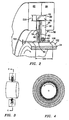
FIG. 2 is a partial semi-schematic longitudinal sectional view of a seal system of the engine ofFIG 1 . -
FIG. 3 is a semi-schematic longitudinal sectional view of the seal system of the engine ofFIG. 1 . -
FIG. 4 is a semi-schematic transverse sectional view of the seal system ofFIG. 3 , taken along line 4-4. -
FIG. 5 is a semi-schematic longitudinal sectional view of the seal system of the engine ofFIG. 1 in an initial excursion stage. -
FIG. 6 is a semi-schematic transverse sectional view of the seal system ofFIG. 5 , taken along line 6-6. -
FIG. 7 is a semi-schematic longitudinal sectional view of the seal system of the engine ofFIG. 1 in a second excursion stage. -
FIG. 8 is a semi-schematic transverse sectional view of the seal system ofFIG. 7 , taken along line 8-8. - Like reference numbers and designations in the various drawings indicate like elements.
-
FIG. 1 shows aturbine engine 20 having ahousing case 22 containing concentric high and lowpressure rotor shafts pressure rotor shaft 24 is driven by the blades of a highpressure turbine section 26 to in turn drive the blades of ahigh pressure compressor 27. The lowpressure rotor shaft 25 is driven by the blades of a lowpressure turbine section 28 to in turn drive the blades of a lowpressure compressor section 29 and afan 30. - The rotor shafts are supported relative to the case by a number of bearing systems. The rotor shafts may be sealed relative to the case by
sealing systems 40 which may include brush sealing elements, labyrinth sealing elements, or the like. -
FIG. 2 shows further details of theexemplary sealing system 40. The system includes abrush seal 50 having abristle pack 52 secured in aseal body 54. The seal body comprises a high pressureside backing plate 56 and a low pressure side backing element formed by the combination of abacking plate 58 and ashield 60. In an exemplary embodiment, thebristle pack 52,backing plate 56,backing plate 58, andshield 60 are of generally annular configuration. Extending downstream from its upstream face along its inboard side, thebacking element 58 has an annular inwardly and upstreamopen compartment 62 containing amagnetic element 64. An exemplary element is formed approximately as a square-section annulus of a permanent magnet. An exemplary permanent magnet is an aluminum-nickel-cobalt (alnico) magnet. Theshield 60 is secured along the upstream faces of thebacking plate 58 andmagnetic element 64. The bristle pack lies along the upstream face of theshield 60 and at its outboard end is secured between the upstream face of the shield and the downstream face of thebacking plate 56. An exemplary securing is by welding (e.g., TIG or electron beam). Extending upstream from its downstream face, thebacking plate 56 has anannular pocket 80 along an inboard portion. Thepocket 80 accommodates the bristles during flexing of the bristles. Theseal 50 is captured within an inwardly-open annular pocket orchannel 84 formed by annular shoulders in a pair of mated upstream anddownstream housing elements radial span 520 between theseal periphery 90 and thebase 92 of thepocket 84. -
FIG. 2 further shows theshaft 24 as having its own magnetic element in the exemplary form of amagnetic coating 100. The coating is applied over a portion of theexterior surface 102 of a metallic component of the shaft. The coating has alongitudinal span 522. The span is advantageously positioned to extend at least partially immediately inboard of themagnetic element 64, more preferably fully beneath such element and, in the illustrated embodiment, more broadly under theentire seal 50. For wear resistance, the magnetic coating may be comprised of magnetic particles in a wear-resistant matrix or may itself be covered by an additional wear-resistant layer. In normal true-running operation, the bristle tips contact the shaft. There is clearance between the inboard surfaces of therigid components radial span 524, although the different components may well have different clearances.FIGS. 3 and 4 show the shaft running in a true condition. -
FIGS. 5 and 6 show an initial excursion of theshaft axis 502 relative to the housing axis 500. The rotor excursion brings the outer surfacemagnetic coating 100 toward the inboard surface of themagnetic element 64 near onediametric location 540 and away therefrom near an oppositediametric location 542. When this occurs, increased magnetic repulsion between thecoating 100 andelement 64 near thelocation 540 and reduced repulsion near thelocation 542 will tend to push the seal to move its axis toward the displacedshaft axis 502. Thus the seal will be shifted within thechannel 84 to at least partially realign the seal axis 504 with the shaft axis 502 (FIGS. 7 and 8 ). If theshaft axis 502 returns to align with the axis 500, a similar magnetic interaction will tend to bring the seal axis back into alignment with both such axes. - One or more embodiments of the present invention have been described. Nevertheless, it will be understood that various modifications may be made without departing from the spirit and scope of the invention. For example, the magnetic coating on the shaft may be replaced by a separately-formed magnetic element. Exemplary elements could include a permanent magnet (e.g., an alnico sleeve on the shaft or a circumferential array of permanent magnet inserts in compartments in the shaft). Similarly, the magnetic element of the seal body could be replaced by a coating or by an array of permanent magnets. Additional features are possible such as a seal anti-rotation features (e.g., radial pins or tabs mounted to the seal and riding in slots in the case). Accordingly, other embodiments are within the scope of the following claims.
Claims (12)
- A seal (50) for providing a seal between inner and outer elements comprising:a flexible sealing element (52) for forming a seal with a first of the inner and outer elements;at least one support element (56,58) secured to the sealing element; andmeans (64) for magnetically interacting with the first element (24) to bias the seal relative to the first element.
- The seal of claim 1 wherein the sealing element comprises a bristle pack (52) having first and second sides and a first portion for sealing with the inner element (24) and a second portion secured to the at least one support element
- The seal of claim 2 wherein the at least one support element comprises at least first and second plates (56,58) at the first and second sides of the bristle pack (52) and carries the means (64) for magnetically interacting.
- The seal of claim 3 wherein:the first plate is a first support plate (56) on a high pressure side of the bristle pack;the second plate is a second support plate (58) on a low pressure side of the bristle pack and carrying the means (64) for magnetically interacting; andthe seal further comprises a shield plate (60) between the second support plate (58) and the bristle pack (52).
- The seal of claim 4 wherein:the second support plate (58) has, extending downstream from its upstream face along its inboard side, an annular inwardly and upstream open compartment (62) containing the means (64).
- The seal of claim 4 or 5 wherein:the first support plate (56) has, extending upstream from its downstream face, an annular pocket (80) along an inboard portion the pocket (80) accommodating the bristles during flexing of the bristles.
- The seal of any preceding claim wherein:the first element is the inner element.
- The seal of any preceding claim being segmented.
- The seal of any preceding claim wherein the means (64) comprises at least one seal magnetic element (64).
- The seal of claim 9 wherein the magnetic element (64) comprises a segmented annular permanent magnet.
- The seal of claim 10 wherein the magnetic element (64) comprises an alnico magnet.
- The seal of any preceding claim being an annular brush seal wherein:the flexible sealing element comprises a bristle pack (52) having first and second sides and an inboard tip portion for forming a seal with the inner element (24) and an outboard root portion;said at least one support element (56,58) is on at least one of the first and second sides secured to the bristle pack (52) and rigid relative to the bristle pack; andthe means comprises at least one seal magnetic element (64) positioned to magnetically interact with inner element (24).
Applications Claiming Priority (2)
| Application Number | Priority Date | Filing Date | Title |
|---|---|---|---|
| US10/330,751 US6910857B2 (en) | 2002-12-26 | 2002-12-26 | Seal |
| EP03257451A EP1433927B1 (en) | 2002-12-26 | 2003-11-26 | Turbine engine and seal |
Related Parent Applications (1)
| Application Number | Title | Priority Date | Filing Date |
|---|---|---|---|
| EP03257451.9 Division | 2003-11-26 |
Publications (1)
| Publication Number | Publication Date |
|---|---|
| EP2199545A1 true EP2199545A1 (en) | 2010-06-23 |
Family
ID=32469046
Family Applications (2)
| Application Number | Title | Priority Date | Filing Date |
|---|---|---|---|
| EP10003565A Withdrawn EP2199545A1 (en) | 2002-12-26 | 2003-11-26 | Seals |
| EP03257451A Expired - Lifetime EP1433927B1 (en) | 2002-12-26 | 2003-11-26 | Turbine engine and seal |
Family Applications After (1)
| Application Number | Title | Priority Date | Filing Date |
|---|---|---|---|
| EP03257451A Expired - Lifetime EP1433927B1 (en) | 2002-12-26 | 2003-11-26 | Turbine engine and seal |
Country Status (3)
| Country | Link |
|---|---|
| US (1) | US6910857B2 (en) |
| EP (2) | EP2199545A1 (en) |
| DE (1) | DE60332702D1 (en) |
Families Citing this family (14)
| Publication number | Priority date | Publication date | Assignee | Title |
|---|---|---|---|---|
| US8199453B2 (en) * | 2003-03-17 | 2012-06-12 | Illinois Tool Works Inc. | Shaft current control brush ring assembly |
| US20070132190A1 (en) * | 2005-12-12 | 2007-06-14 | Charles Trabert | Axial dynamic brush seal |
| US7458584B2 (en) | 2007-02-27 | 2008-12-02 | United Technologies Corporation | Reverse flow tolerant brush seal |
| US20100006788A1 (en) * | 2008-07-09 | 2010-01-14 | Honeywell International Inc. | Valve assembly having magnetically-energized seal mechanism |
| WO2012105301A1 (en) * | 2011-02-03 | 2012-08-09 | イーグル工業株式会社 | Magnetic fluid seal |
| US9708923B2 (en) * | 2013-11-13 | 2017-07-18 | Dresser-Rand Company | Adjustable labyrinth seal |
| EP3339581A1 (en) * | 2016-12-22 | 2018-06-27 | Ansaldo Energia S.p.A. | Sealing system for a rotating machine |
| US10931179B2 (en) * | 2018-03-20 | 2021-02-23 | Aktiebolaget Skf | Fiber grounding brush |
| US10927692B2 (en) * | 2018-08-06 | 2021-02-23 | General Electric Company | Turbomachinery sealing apparatus and method |
| CN109578086B (en) * | 2018-11-08 | 2021-07-30 | 北京北冶功能材料有限公司 | A composite brush type sealing structure |
| US11519288B2 (en) * | 2020-12-18 | 2022-12-06 | General Electric Company | Turbomachine clearance control using brush seals having magnetically responsive filaments |
| US11434777B2 (en) * | 2020-12-18 | 2022-09-06 | General Electric Company | Turbomachine clearance control using magnetically responsive particles |
| CN113090339B (en) * | 2021-04-08 | 2022-08-02 | 沈阳航空航天大学 | Active gap control brush seal structure based on magnetic attraction effect |
| CN116480619A (en) * | 2022-01-17 | 2023-07-25 | 开利公司 | Sealing system for magnetic levitation centrifugal compressor and magnetic levitation centrifugal compressor |
Citations (3)
| Publication number | Priority date | Publication date | Assignee | Title |
|---|---|---|---|---|
| US5137286A (en) * | 1991-08-23 | 1992-08-11 | General Electric Company | Permanent magnet floating shaft seal |
| US6168162B1 (en) * | 1998-08-05 | 2001-01-02 | General Electric Co. | Self-centering brush seal |
| US6220602B1 (en) * | 1998-04-17 | 2001-04-24 | Rolls-Royce Plc | Seal arrangement |
Family Cites Families (9)
| Publication number | Priority date | Publication date | Assignee | Title |
|---|---|---|---|---|
| US2883212A (en) * | 1956-08-23 | 1959-04-21 | City Nat Bank And Trust Compan | Labyrinth type magnetic rotary seal |
| US5201530A (en) * | 1991-10-18 | 1993-04-13 | United Technologies Corporation | Multi-layered brush seal |
| US5351971A (en) * | 1993-05-21 | 1994-10-04 | Eg&G Sealol, Inc. | Brush seal device having a floating backplate |
| US5452957A (en) * | 1994-11-22 | 1995-09-26 | Dana Corporation | Center bearing assembly including support member containing rheological fluid |
| US5599026A (en) * | 1995-09-06 | 1997-02-04 | Innovative Technology, L.L.C. | Turbine seal with sealing strip and rubbing strip |
| US6318728B1 (en) * | 1997-07-11 | 2001-11-20 | Demag Delaval Turbomachinery Corporation | Brush-seal designs for elastic fluid turbines |
| US6746019B1 (en) * | 1999-08-27 | 2004-06-08 | Eskom | Seal assembly |
| GB2363864B (en) * | 2000-06-23 | 2004-08-18 | Rolls Royce Plc | A control arrangement |
| US6390476B1 (en) * | 2000-09-08 | 2002-05-21 | General Electric Company | Heat-resistant magnetic silicone rubber brush seals in turbomachinery and methods of application |
-
2002
- 2002-12-26 US US10/330,751 patent/US6910857B2/en not_active Expired - Lifetime
-
2003
- 2003-11-26 EP EP10003565A patent/EP2199545A1/en not_active Withdrawn
- 2003-11-26 EP EP03257451A patent/EP1433927B1/en not_active Expired - Lifetime
- 2003-11-26 DE DE60332702T patent/DE60332702D1/en not_active Expired - Lifetime
Patent Citations (3)
| Publication number | Priority date | Publication date | Assignee | Title |
|---|---|---|---|---|
| US5137286A (en) * | 1991-08-23 | 1992-08-11 | General Electric Company | Permanent magnet floating shaft seal |
| US6220602B1 (en) * | 1998-04-17 | 2001-04-24 | Rolls-Royce Plc | Seal arrangement |
| US6168162B1 (en) * | 1998-08-05 | 2001-01-02 | General Electric Co. | Self-centering brush seal |
Also Published As
| Publication number | Publication date |
|---|---|
| DE60332702D1 (en) | 2010-07-08 |
| EP1433927A3 (en) | 2006-06-28 |
| EP1433927A2 (en) | 2004-06-30 |
| EP1433927B1 (en) | 2010-05-26 |
| US6910857B2 (en) | 2005-06-28 |
| US20040126226A1 (en) | 2004-07-01 |
Similar Documents
| Publication | Publication Date | Title |
|---|---|---|
| US6910857B2 (en) | Seal | |
| US5785492A (en) | Method and apparatus for sealing a gas turbine stator vane assembly | |
| US5593164A (en) | Ferrofluidic seal centering ring | |
| EP2749795B1 (en) | Shaft sealing device and rotating machine comprising same | |
| CA2232166A1 (en) | Brush seal having bristles tilted in the circumferential direction | |
| EP1244881B1 (en) | Brush seals | |
| US8794631B2 (en) | Method of manufacturing of a compliant plate seal assembly | |
| EP0406646A2 (en) | Fluid seal structure | |
| US8028996B2 (en) | System and method for adjusting stiffness of a brush sealing system | |
| JPH11247999A (en) | Seal device of rotary machine | |
| JP2006342812A (en) | Component of gas turbine engine | |
| US8167313B2 (en) | Seal member, assembly and method | |
| US4754983A (en) | Sealing apparatus between rotatable coaxial inner and outer shafts of a gas turbine engine | |
| US7270333B2 (en) | Brush seal with adjustable clearance | |
| CN102563074A (en) | Air cycle machine seal plate and seal land | |
| EP2275723B1 (en) | Seal support | |
| EP0382333A1 (en) | Mounting arrangement of segmental members in rotary machines | |
| US6808180B2 (en) | Brush seal | |
| EP1963642A2 (en) | Axial dynamic brush seal | |
| EP3270014B1 (en) | Divided-type brush seal device | |
| US6910858B2 (en) | Seal | |
| EP1113201B1 (en) | Brush seal and segment for rotary machines such as turbines | |
| EP0345944A2 (en) | Mechanical seal assembly | |
| JPH10148198A (en) | Shaft sealing device | |
| JPH09287405A (en) | Non-contact seal |
Legal Events
| Date | Code | Title | Description |
|---|---|---|---|
| PUAI | Public reference made under article 153(3) epc to a published international application that has entered the european phase |
Free format text: ORIGINAL CODE: 0009012 |
|
| AC | Divisional application: reference to earlier application |
Ref document number: 1433927 Country of ref document: EP Kind code of ref document: P |
|
| AK | Designated contracting states |
Kind code of ref document: A1 Designated state(s): DE FR GB IT NL |
|
| 17P | Request for examination filed |
Effective date: 20101221 |
|
| 17Q | First examination report despatched |
Effective date: 20130305 |
|
| STAA | Information on the status of an ep patent application or granted ep patent |
Free format text: STATUS: THE APPLICATION IS DEEMED TO BE WITHDRAWN |
|
| 18D | Application deemed to be withdrawn |
Effective date: 20140603 |