EP2199204A2 - Aircraft engine nacelle with translating inlet cowl - Google Patents
Aircraft engine nacelle with translating inlet cowl Download PDFInfo
- Publication number
- EP2199204A2 EP2199204A2 EP20090015442 EP09015442A EP2199204A2 EP 2199204 A2 EP2199204 A2 EP 2199204A2 EP 20090015442 EP20090015442 EP 20090015442 EP 09015442 A EP09015442 A EP 09015442A EP 2199204 A2 EP2199204 A2 EP 2199204A2
- Authority
- EP
- European Patent Office
- Prior art keywords
- inlet
- nacelle
- edge
- aft
- inner barrel
- Prior art date
- Legal status (The legal status is an assumption and is not a legal conclusion. Google has not performed a legal analysis and makes no representation as to the accuracy of the status listed.)
- Granted
Links
Images








Classifications
-
- B—PERFORMING OPERATIONS; TRANSPORTING
- B64—AIRCRAFT; AVIATION; COSMONAUTICS
- B64D—EQUIPMENT FOR FITTING IN OR TO AIRCRAFT; FLIGHT SUITS; PARACHUTES; ARRANGEMENT OR MOUNTING OF POWER PLANTS OR PROPULSION TRANSMISSIONS IN AIRCRAFT
- B64D29/00—Power-plant nacelles, fairings or cowlings
-
- Y—GENERAL TAGGING OF NEW TECHNOLOGICAL DEVELOPMENTS; GENERAL TAGGING OF CROSS-SECTIONAL TECHNOLOGIES SPANNING OVER SEVERAL SECTIONS OF THE IPC; TECHNICAL SUBJECTS COVERED BY FORMER USPC CROSS-REFERENCE ART COLLECTIONS [XRACs] AND DIGESTS
- Y10—TECHNICAL SUBJECTS COVERED BY FORMER USPC
- Y10T—TECHNICAL SUBJECTS COVERED BY FORMER US CLASSIFICATION
- Y10T137/00—Fluid handling
- Y10T137/0536—Highspeed fluid intake means [e.g., jet engine intake]
Definitions
- the invention relates to nacelles for aircraft engines, and more particularly relates to a nacelle for a turbofan engine that includes a translating inlet cowl.
- a nacelle for a turbofan engine for an aircraft The functions of a nacelle for a turbofan engine for an aircraft are generally twofold. First, the nacelle directs air flow to the air intake of the engine while protecting the air flow from disturbances such as gusts, and the like. Second, the exterior surface profile of the nacelle minimizes the aerodynamic drag caused by the engine and its related components.
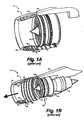
- a turbofan engine assembly 10 includes a nacelle structure 22 and a fan case 16.
- a nacelle structure 22 is removed for ease of illustration.
- the fan case 16 surrounds the fan blades 18 of an engine 12.
- the nacelle structure 22 includes a forward nacelle portion 24 and a rearward nacelle portion 25.
- Fig. 1B the nacelle structure 22 includes a forward nacelle portion 24 and a rearward nacelle portion 25.
- the forward nacelle portion 24 includes an outer skin 32, a noselip portion 28, an inner skin 30, and a plurality of bulkheads 34, 36 disposed between the outer skin 32 and the inner skin 30.
- the forward nacelle portion 24 is movably mounted to an aircraft's pylon structure 26 by a beam 52.
- the beam 52 permits the forward nacelle portion 24 to translate between a retracted operational position shown in Fig. 1A , and an extended service position shown in Fig. 1B .
- the forward nacelle portion 24 is in the extended service position shown in Fig.
- an opening 40 between the aft edge of the forward nacelle portion 24 and the forward edge of the rearward nacelle portion 25 provides service access to various engine accessories, such as an engine's gearbox, electrical generators, and the like.
- the forward edge of the fan case 16 is releasably engaged with the aft edge of the inner barrel 30 to provide a substantially continuous inner surface.
- the nacelle structure 22 described in U.S. Patent No. 6,340,135 can be improved.
- a nacelle structure having an interface between the inlet inner barrel and the fan case that is resistant to substantial damage from a blade out event, and can thus help to provide fly home capability following such an event.
- a "blade out event" arises when a blade is accidentally released from a turbine's rotor, such as when a first-stage fan blade is accidentally released in a high-bypass gas turbine engine.
- U.S. Federal Aviation Administration (FAA) regulations require that certain structures be designed to sufficiently withstand such an event so that safe operation of an associated aircraft can be maintained.
- FAA Federal Aviation Administration
- a nacelle structure for a turbofan aircraft engine that is even lower in weight, and thus contributes to further increases in aircraft efficiency.
- a nacelle as defined in claim 1.
- the nacelle in one embodiment of the invention, includes an inlet inner barrel having an inner barrel forward edge and an inner barrel aft edge.
- the inner barrel aft edge is configured to be affixed to the fan case forward edge in a stationary position on the engine.
- the nacelle also includes a translating inlet cowl having an inlet lip with an aft inlet lip edge and an outer skin with rear edge.
- the translating inlet cowl is configured to be movably attached to one or more stationary portions of the engine such that the inlet cowl is selectively movable between a stowed flight position and an extended service position.
- the nacelle in another embodiment, includes a translating inlet cowl having an inlet lip with an inlet lip aft inner edge and an outer skin with a rear edge, and a stationary aft nacelle portion including a front outer edge.
- the nacelle further includes an inlet inner barrel having an inlet inner barrel forward edge and an inlet inner barrel aft edge.
- the inlet inner barrel aft edge can be configured to be affixed to the fan case forward edge in a stationary position.
- the translating inlet cowl is movable between a stowed flight position and an extended service position, wherein the inlet lip aft inner edge is adjacent to the inlet inner barrel forward edge when the translating inlet cowl portion is in the stowed flight position, and wherein a service opening is formed between the rear edge of the outer skin and the front edge of the aft nacelle portion when the translating inlet cowl is in the extended service position.
- a nacelle for a turbofan aircraft engine having a fan case includes a translating inlet cowl and a support beam affixed to the engine fan case.
- the support beam substantially supports the translating inlet cowl on the engine, and is configured to permit the translating inlet cowl to be selectively translated between a stowed flight position and an extended service position.
- the invention provides a nacelle for a turbofan aircraft engine having a fan case with a fan case forward edge includes an inlet inner barrel having an inner barrel forward edge and an inner barrel aft edge.
- the inner barrel aft edge is configured to be affixed to the fan case forward edge in a stationary position on the engine.
- the nacelle also includes a translating inlet cowl haying an inlet lip with an aft inlet lip edge and an outer skin with rear edge.
- the translating inlet cowl is configured to be movably attached to one or more stationary portions of the engine such that the inlet cowl is selectively movable between a stowed flight position and an extended service position.
- a turbofan aircraft engine assembly 100 equipped with a nacelle 120 is shown in Figs. 2A and 2B .
- the nacelle 120 shrouds an engine 110, and includes a translating inlet cowl 124 and an aft nacelle portion 125.
- the aft outer edge 124b of the translating inlet cowl 124 adjoins a forward outer edge 125a of the aft nacelle portion 125 along an aft outer joint 121.
- the translating inlet 124 can be removably connected to the aft cowl 125 by a plurality of circumferentially spaced latches 103.
- the latches 103 can be manually operated latches of a type known in the art.
- the latches 103 can provide an alternate load path between the translating inlet cowl 124 and the aft nacelle portion 125 that can contribute to the fly home integrity of an associated aircraft in the case of a blade out event.
- the latches 103 also can pretension a forward joint 101 between an inner barrel 127 and a noselip 128 (shown in Figs. 3A and 4 ).
- the translating inlet cowl 124 is translated forward such that an access opening 130 is formed between the aft outer edge 124b of the translating inlet cowl 124 and the forward outer edge 125a of the aft nacelle portion 125.
- the access opening 130 facilitates access to fan-mounted engine accessories 132 that are located proximate to the opening 130, such as the engine's gearbox, variable frequency starter generator (VFSG), terminal block interface, oil tank, and the like.
- VFSG variable frequency starter generator
- the relative movement between the stationary aft nacelle portion 125 and the translating inlet cowl 124 is further illustrated in the cross-sectional views of Figs. 3A and 3B .
- the aft outer edge 124b of the translating inlet cowl 124 can overlap the forward outer edge 125a of the aft nacelle portion 125 along the aft outer joint 121.
- the translating inlet cowl 124 can include an inlet lip 128 and an outer skin 129.
- An inner barrel section 127 can be affixed to a fan case 116. In the configuration shown in Fig.
- the aft edge 127b of the inner barrel 127 and the forward edge 116a of the fan case liner 116 are joined along an interior joint 203.
- the adjoining edges 127b, 116a of the inner barrel 127 and the fan case liner 116 can be connected together using mechanical fasteners such as bolts or rivets, or the like.
- the connected inner barrel section 127 and the interior joint 203 can be eliminated, and the fan case 116 can be extended to the forward joint 101.
- an inner aft edge 128b of the noselip 128 adjoins the forward edge 127a of the inner barrel section 127 along a forward interior joint 101.
- the forward nacelle portion 124 is translated forward relative to the aft nacelle portion 125, thus forming the service access opening 130 therebetween.
- the opening 130 provides substantially unobstructed exterior access to the outer surface of the fan case 116 and to any accessory equipment mounted or situated therearound.
- the translating inlet cowl 124 can be movably supported by a support beam assembly 150, 160 and by one or more side stabilizing beams 167.
- a substantial portion of the weight of the translating inlet cowl 124 can be borne by the support beam assembly 150, 160, and the side stabilizing beams 167 primarily assist in maintaining alignment and stability of the translating inlet cowl 124 when the cowl 124 is translated forward.
- the translating inlet cowl 124 is supported by two side stabilizing beams 167, each positioned proximate to a lateral side of the engine assembly 100.
- Support beam assemblies 150 and 160 are alternate embodiments for movably supporting the translating inlet cowl 124, and are described below.
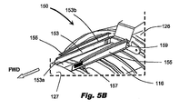
- the support beam assembly 150 includes an elongated beam 153 and a pair of opposed sliding members 155.
- the sliding members 155 can be securely attached to the translating inlet cowl's outer skin 129.
- the sliding members 155 are slidably engaged on the beam 153.
- the sliding members 155 are shown in their fully retracted positions on the beam 153.
- the aft end 153b of the beam 153 is attached to a forward portion of an engine pylon 126 by a pair of clevis-type connectors 159, and the forward end 153a of the beam 153 is connected to the fan case liner 116 by one or more brackets 157.
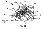
- a support beam assembly 160 includes an elongated beam 163 and a pair of opposed sliding members 165.
- the sliding members 165 can be securely attached to the translating inlet cowl's outer skin 129, and are slidably engaged on the beam 163.
- the sliding members 165 are shown in their fully retracted positions on the beam 163.
- the aft end 163b of the beam 163 is attached to an aft portion of the fan case liner 116 by one or more trunnions or brackets 169, and the forward end 163a of the beam 163 is connected to a forward end of the fan case liner 116 by one or more brackets or tie rods 167, or the like.
- the beam 163 can include one or more stiffeners 161 to provide a more rigid beam structure.
- the beam 153 of support beam assembly 150 can also include one or more similar stiffeners.
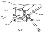
- the sliding members 155, 165 each include a slide 158, 168 that is engaged with a single rail 156, 166 on the beam 153, 163.
- a plurality of ball bearings can be disposed between the slides 158, 168 and the single rails 156, 166 to minimize friction and facilitate relative sliding movement between the sliding members 155, 165 and the beams 153, 163 (not shown in Figs. 7 and 8 ).
- forward translation of the slide 158, 168 in the single rail 156, 166 permits the sliding members 155, 165 to translate forward of the beam 153, 163.
- the maximum distance that the sliding members 155, 165 can translate forward of the beam 153, 163 is limited by the length of the single rail 156, 166.
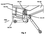
- the sliding members 155, 165 each include a first slide 151, 161 that is engaged with a first side of a double rail 152, 162 on the beam 153, 163, and a second slide 154, 164 on the beam 153, 163 is engaged with a second side of the double rail 152, 162.
- the double rail 152, 162 can translate forward of the beam 153, 163 on the second slide 154, 164, and the sliding members 155, 165 and first slides 151, 161 can translate forward of the extended double rail 152, 162.
- the maximum distance that the sliding members 155, 165 can translate forward of the beam 153, 163 is almost twice the length of the double rail 152, 162. Accordingly, when the single rails 156, 166 ( Fig. 7 ) and the double rails 152, 162 ( Fig. 8 ) have equal lengths, the double-rail configuration shown in Fig. 8 permits approximately twice the translational displacement between the sliding members 155, 165 and the beam 153, 163 as the single-rail arrangement shown in Fig. 7 .
- a plurality of ball bearings can be disposed between the slides 154, 164 and the rails 152, 162 to minimize friction and facilitate relative sliding movement between the sliding members 155, 165 and the beams 153, 163 (not shown in Figs. 7 and 8 ).
- the translating cowl can be manually pushed forward to provide access to the fan case mounted accessories.
- FIG. 9 One embodiment of a system for translating an inlet cowl 124 between its retracted and extended positions is shown in Figs. 9-11 .
- one or more linear actuators 170, 172 can be provided for automatically moving the inlet cowl 124 between its stowed and service positions.
- a linear actuator 170, 172 is provided on each lateral side of the fan case liner 116, wherein the two actuators 170, 172 are substantially equidistant from the support beam 150, 160.
- first and second actuators 170, 172 can be ball screw actuators.
- first and second actuators 170, 172 each include a ball screw 173 having a forward end engaged with a forward ball screw support 175, and an aft end engaged with an aft ball screw support 177.
- the aft tip 202 of the ball screw 173 of an actuator 170 can outwardly extend from its associated aft ball screw support 177.
- the aft ball screw support 177 and/or tip 202 can include a hex configuration for driving engagement with an air motor or other powered rotational tool or device (not shown).
- the two forward ball screw supports 175 can be connected by a synchronizing cable 179 such that powered rotation of one ball screw 173 will result in simultaneous and synchronized rotation of the other ball screw 173.
- the forward ball screw supports 175 and the aft ball screw supports 177 can be connected to the fan case 116. Selective rotation of the screws 173 results in translational displacement of the face plates 203 and the inlet cowl 124 connected thereto. Accordingly, the inlet cowl 124 can be translated in forward and aft directions relative to the fan case 116 (as previously shown in Figs. 3A and 3B ) by selective rotation of the ball screws 173.
- the inlet cowl 124 and inner barrel 127 can include clocking fittings 182, 184 in order to maintain rotational alignment between the translating inlet cowl 124 and the inner barrel 127.
- the clocking fittings can include mating V-shaped male and female members 182, 184 that engage each other when the aft edge 128b of the inlet lip 128 is retracted against the forward edge 127a of the inner barrel 127.
- a male V-block 182 is affixed to an aft portion 128b of the inlet lip 128, and a mating female V-block 184 is affixed to a forward portion 127a of the inner barrel 127.
- One or more pairs of mating blocks 182, 184 can be circumferentially spaced around the inlet lip 128 and the inner barrel 127.
- Figs. 13A-15C show embodiments of two latching systems 190, 220 that may be used to latch the translating inlet cowl to the inner barrel in the stowed flight position.
- a mechanical latching system 190 is integrated with the ball-screw linear actuators 170, 172 described above.
- the latching system 190 includes a pair of ring segments 191, 193.
- Each ring segment 191, 193 includes a plurality of circumferentially spaced latch assemblies 196.
- the aft ball screw support 177 on the aft end of the left-side actuator 172 can include an aft ball screw receiver 207 joined to the engine fan case 116 via the aft ball screw support bracket 251.
- the face plate 203 can be affixed to the outer skin 129 (not shown in Fig. 13B ).
- the aft push rod fitting 205 is slidably engaged with the face plate slide 208 on the face plate 203. As also shown in Fig.
- the forward ball screw support 175 on the forward end of the left-side actuator 172 (as best shown in the enlarged altered detail in the lower left portion of Fig. 13B ) includes a forward ball screw receiver 204 and a forward support block 206.
- the forward support block 206 can be affixed to a portion of the fan case 116.
- each latch assembly 196 (as best shown in the enlarged altered detail in the upper left portion of Fig. 13B ) includes a slide base 211 with a latch ring slide 219, and a strike 213 slidably engaged in the latch ring slide 219.
- the slide base 211 can be affixed to the outer skin 129 of the translatable inlet cowl 124 (see Fig. 14C ).
- a hook-shaped latch catch 217 is pivotally mounted to a pivot fitting 215, which can be affixed to a forward portion of the inlet inner barrel 127 (see Fig. 14B ).
- the latch catches 217 can be biased by springs toward a latched position, wherein the latch catches 217 grab the aft edge 128b of the inlet lip 128, and clamp the inlet lip 128 to the forward edge 127a of the inner barrel 127 (see Fig. 14C ). As shown in Fig.
- a push rod 199 extends between the aft push rod fitting 205 and a forward push rod fitting 202 affixed to the latch ring segment 191.
- the right side portion 192 of the mechanical latching system shown in Fig. 13A can be a mirror image of the left side portion shown in detail in Fig. 13B .
- the translatable inlet cowl is initially in its stowed flight position, and the spring loaded latch catches 217 described above are initially engaged with the inlet lip.
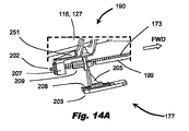
- initial clockwise rotation of the end 202 of the ball screw 173 with an air motor or other rotating tool causes the ball screw nut 209, the aft push rod fitting 205, and the attached push rod 199 to move in a forward direction relative to the face plate 203, with the aft push rod fitting 205 sliding within the face plate slide 208.
- Fig. 14A initial clockwise rotation of the end 202 of the ball screw 173 with an air motor or other rotating tool causes the ball screw nut 209, the aft push rod fitting 205, and the attached push rod 199 to move in a forward direction relative to the face plate 203, with the aft push rod fitting 205 sliding within the face plate slide 208.
- the initial forward movement of the push rod 199 results in corresponding forward movement of the latch ring segment 191 and the affixed strike 213.
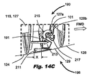
- Fig. 14C as the wedge-shaped strike 213 moves forward, contact with the corresponding latch catch 217 causes the latch catch 217 to rotate away from its fully latched engagement with the aft edge 128b of the inlet lip 128.
- Fig. 14D once the aft push rod fitting 205 has moved a distance "x" and reaches the end of the face plate slide 208, the aft push rod fitting 205 is prevented from moving further in a forward direction with respect to the face plate 203.
- the spring-loaded latch catches 217 are free to engage portions of the inlet lip 128, and thereby latch the inlet cowl 124 to the fan case 116 and inner barrel 127.
- each latch 220 includes a catch 225 pivotally mounted on a bracket 221.
- the bracket 221 is attached to the inner barrel 127 proximate to the inner barrel's forward edge 127a.
- An electrical actuator 223 such as a rotary solenoid controls movement and positioning of the catch 225 between the latched position shown in Fig. 15A and the fully unlatched positions shown in Figs. 15B and 15C .
- a plurality of electromechanical latches 220 can be circumferentially spaced around the joint 101 between the forward edge 127a of the inlet inner barrel 127 and the aft inner edge 128b of the inlet lip 128.
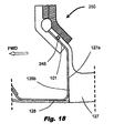
- Figs. 16-18 show three embodiments of a substantially air-tight and aligned interface along the joint 101 between the forward edge 127a of the inlet inner barrel 127 and the aft inner edge 128b of the inlet lip 128 when the translating inlet cowl 124 is in its stowed flight position (as shown in Fig. 3A ).
- the inlet inner barrel 127 includes a first flange 231
- the inlet lip 128 includes a corresponding second flange 232.
- the first flange 231 can include a plurality of receptacles 233 distributed evenly around the forward joint 101, and the second flange 232 can include a plurality of tapered pins 234 that align the lip 128 and the inner barrel 127 when the nacelle is in its flight configuration.
- a seal member 201 of a resilient material such as rubber can be provided within a circumferential cavity 299 in the first flange 231. The seal 201 can be compressed against the adjacent surface of the second flange 232 to provide an aerodynamic seal when the inlet cowl 124 is in its stowed flight position.
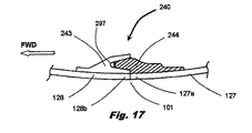
- a female member 243 on the aft edge 128b of the inlet lip 128 receives a male member 244 on the forward edge 127a of the inner barrel 127.
- neither the inlet lip 128 nor the inner barrel 127 requires an upstanding flange.
- a seal 297 of a resilient material such as rubber, for example, can be disposed between the tip of male member 244 and the bottom of the recess in female member 243. The seal 297 can be compressed between the male and female members 243, 244 to provide an aerodynamic seal when the inlet cowl 124 is in its stowed flight position.
- the aft edge 128b of the inlet lip 128 can have a conical shape, and can mate with a conically shaped forward edge 127a of the inner barrel 127.
- the edges 128b, 127a align to provide an aerodynamic joint 101.
- a seal 245 can be installed between the mating conical edges 128b, 127a to aerodynamically seal the joint 101.
- Affixing the inner barrel 127 to the fan case 116 in a stationary position provides a strong, durable and efficient structure that enhances the ability of the inner barrel 127 and the fan case 116 to endure a blade out event, and to support an aircraft's subsequent fly home capability.
- the translating nacelle structure described above also provides substantial reductions in weight that benefit aircraft efficiency.
- the nacelle structure can be approximately 40-50 pounds lighter than a comparable nacelle structure like that described in U.S. Patent No. 6,340,135 .
Landscapes
- Engineering & Computer Science (AREA)
- Aviation & Aerospace Engineering (AREA)
- Structures Of Non-Positive Displacement Pumps (AREA)
Abstract
Description
- The invention relates to nacelles for aircraft engines, and more particularly relates to a nacelle for a turbofan engine that includes a translating inlet cowl.
- The functions of a nacelle for a turbofan engine for an aircraft are generally twofold. First, the nacelle directs air flow to the air intake of the engine while protecting the air flow from disturbances such as gusts, and the like. Second, the exterior surface profile of the nacelle minimizes the aerodynamic drag caused by the engine and its related components.
- One design of a nacelle for a turbofan aircraft engine is described in
U.S. Patent No. 6,340,135 assigned to Rohr, Inc., and is shown inFigs. 1A and 1B . As shown inFigs. 1A and 1B , aturbofan engine assembly 10 includes anacelle structure 22 and a fan case 16. InFigs.1A and 1B , one side of thenacelle structure 22 is removed for ease of illustration. The fan case 16 surrounds thefan blades 18 of an engine 12. As shown inFig. 1B , thenacelle structure 22 includes a forward nacelle portion 24 and a rearward nacelle portion 25. As also shown inFig. 1B , the forward nacelle portion 24 includes an outer skin 32, anoselip portion 28, an inner skin 30, and a plurality of bulkheads 34, 36 disposed between the outer skin 32 and the inner skin 30. The forward nacelle portion 24 is movably mounted to an aircraft's pylon structure 26 by a beam 52. The beam 52 permits the forward nacelle portion 24 to translate between a retracted operational position shown inFig. 1A , and an extended service position shown inFig. 1B . When the forward nacelle portion 24 is in the extended service position shown inFig. 1B , an opening 40 between the aft edge of the forward nacelle portion 24 and the forward edge of the rearward nacelle portion 25 provides service access to various engine accessories, such as an engine's gearbox, electrical generators, and the like. When the forward nacelle portion 24 is in the operational position shown inFig. 1A , the forward edge of the fan case 16 is releasably engaged with the aft edge of the inner barrel 30 to provide a substantially continuous inner surface. - The
nacelle structure 22 described inU.S. Patent No. 6,340,135 can be improved. In particular, there is a need for a nacelle structure having an interface between the inlet inner barrel and the fan case that is resistant to substantial damage from a blade out event, and can thus help to provide fly home capability following such an event. As is known in the art, a "blade out event" arises when a blade is accidentally released from a turbine's rotor, such as when a first-stage fan blade is accidentally released in a high-bypass gas turbine engine. U.S. Federal Aviation Administration (FAA) regulations require that certain structures be designed to sufficiently withstand such an event so that safe operation of an associated aircraft can be maintained. In addition, there is a need for a nacelle structure for a turbofan aircraft engine that is even lower in weight, and thus contributes to further increases in aircraft efficiency. - According to the invention there is provided a nacelle as defined in claim 1.
- In one embodiment of the invention, the nacelle includes an inlet inner barrel having an inner barrel forward edge and an inner barrel aft edge. The inner barrel aft edge is configured to be affixed to the fan case forward edge in a stationary position on the engine. The nacelle also includes a translating inlet cowl having an inlet lip with an aft inlet lip edge and an outer skin with rear edge. The translating inlet cowl is configured to be movably attached to one or more stationary portions of the engine such that the inlet cowl is selectively movable between a stowed flight position and an extended service position.
- In another embodiment, the nacelle includes a translating inlet cowl having an inlet lip with an inlet lip aft inner edge and an outer skin with a rear edge, and a stationary aft nacelle portion including a front outer edge. The nacelle further includes an inlet inner barrel having an inlet inner barrel forward edge and an inlet inner barrel aft edge. The inlet inner barrel aft edge can be configured to be affixed to the fan case forward edge in a stationary position. The translating inlet cowl is movable between a stowed flight position and an extended service position, wherein the inlet lip aft inner edge is adjacent to the inlet inner barrel forward edge when the translating inlet cowl portion is in the stowed flight position, and wherein a service opening is formed between the rear edge of the outer skin and the front edge of the aft nacelle portion when the translating inlet cowl is in the extended service position.
- In another embodiment, a nacelle for a turbofan aircraft engine having a fan case includes a translating inlet cowl and a support beam affixed to the engine fan case. The support beam substantially supports the translating inlet cowl on the engine, and is configured to permit the translating inlet cowl to be selectively translated between a stowed flight position and an extended service position.
- Broadly speaking, the invention provides a nacelle for a turbofan aircraft engine having a fan case with a fan case forward edge includes an inlet inner barrel having an inner barrel forward edge and an inner barrel aft edge. The inner barrel aft edge is configured to be affixed to the fan case forward edge in a stationary position on the engine. The nacelle also includes a translating inlet cowl haying an inlet lip with an aft inlet lip edge and an outer skin with rear edge. The translating inlet cowl is configured to be movably attached to one or more stationary portions of the engine such that the inlet cowl is selectively movable between a stowed flight position and an extended service position.
- These and other aspects of the invention will be understood from a reading of the following detailed description together with the drawings, in which
-
Fig. 1A is a perspective view of a prior art aircraft engine nacelle with a translating inlet cowl in its retracted operational position; -
Fig. 1B is a perspective view of the prior art aircraft engine nacelle shown inFig. 1B with the translating inlet cowl in its extended service position; -
Fig. 2A is a side elevation view of a turbofan aircraft engine that includes a nacelle according to one embodiment of the invention with the translating forward portion of the nacelle in a retracted operational position; -
Fig. 2B is a side elevation view of the turbofan aircraft engine shown inFig. 2A with the translating forward portion of the nacelle in an extended service position; -
Fig. 3A is a partial longitudinal cross-sectional view of the turbofan aircraft engine shown in -
Figs. 2A and2B with the translating forward portion of the nacelle in a retracted operational position; -
Fig. 3B is a partial longitudinal cross-sectional view of the turbofan aircraft engine shown in -
Figs. 2A and2B with the translating forward portion of the nacelle in an extended service position; -
Fig. 4 is a front perspective view of the turbofan aircraft engine shown inFigs. 2A-3B ; -
Fig. 5A is a side elevation view of a support tray for movably mounting the translating forward portion of the nacelle to fixed portions of a turbofan engine assembly; -
Fig. 5B is a perspective view of the support tray shown inFig. 5A ; -
Fig. 6A is a side elevation view of another embodiment of a support tray for movably mounting the translating forward portion of the nacelle to fixed portions of a turbofan engine assembly; -
Fig. 6B is a perspective view of the support tray shown inFig. 6A ; -
Fig. 7 is a perspective view showing details of the support tray shown inFigs. 5A-6B ; -
Fig. 8 is a perspective view showing alternative details of the support tray shown inFigs. 5A-6B ; -
Fig. 9 is a front cross-sectional view of portions of a nacelle assembly according to the invention taken along section line 9-9 inFig. 2B ; -
Fig. 10 is a perspective view of an actuator for moving a forward nacelle portion between a retracted operational position and an extended service position; -
Fig. 11 is a perspective view of another actuator for moving a forward nacelle portion between a retracted operational position and an extended service position; -
Fig. 12 is a partial perspective view of a nacelle structure according to the invention showing a pair of clocking fittings; -
Fig. 13A is a perspective view of one embodiment of a mechanical latching system for selectively latching a nacelle inlet lip to an inner barrel; -
Fig. 13B is a partial perspective view of the mechanical latching system shown inFig. 13A showing various details of the system; -
Figs. 14A-14D illustrate a sequence of operation of the latching system shown inFigs. 13A and13B ; -
Figs. 15A-15C illustrate a sequence of operation of one embodiment of an electromechanical latching system for selectively latching a nacelle inlet lip to an inner barrel; -
Fig. 16 is a longitudinal cross-sectional view of one embodiment of a mating interface between an aft edge of a movable inlet lip and a forward edge of a stationary inner barrel; -
Fig. 17 is a longitudinal cross-sectional view of another embodiment of a mating interface between an aft edge of a movable inlet lip and a forward edge of a stationary inner barrel; and -
Fig. 18 is a longitudinal cross-sectional view of yet another embodiment of a mating interface between an aft edge of a movable inlet lip and a forward edge of a stationary inner barrel. - A turbofan
aircraft engine assembly 100 equipped with anacelle 120 according to one embodiment of the invention is shown inFigs. 2A and2B . Thenacelle 120 shrouds anengine 110, and includes a translatinginlet cowl 124 and anaft nacelle portion 125. In a flight configuration shown inFig. 2A , the aftouter edge 124b of the translatinginlet cowl 124 adjoins a forwardouter edge 125a of theaft nacelle portion 125 along an aft outer joint 121. The translatinginlet 124 can be removably connected to theaft cowl 125 by a plurality of circumferentially spaced latches 103. Thelatches 103 can be manually operated latches of a type known in the art. Thelatches 103 can provide an alternate load path between the translatinginlet cowl 124 and theaft nacelle portion 125 that can contribute to the fly home integrity of an associated aircraft in the case of a blade out event. Thelatches 103 also can pretension a forward joint 101 between aninner barrel 127 and a noselip 128 (shown inFigs. 3A and4 ). - In a service access configuration shown in
Fig. 2B , the translatinginlet cowl 124 is translated forward such that anaccess opening 130 is formed between the aftouter edge 124b of the translatinginlet cowl 124 and the forwardouter edge 125a of theaft nacelle portion 125. Theaccess opening 130 facilitates access to fan-mountedengine accessories 132 that are located proximate to theopening 130, such as the engine's gearbox, variable frequency starter generator (VFSG), terminal block interface, oil tank, and the like. - The relative movement between the stationary
aft nacelle portion 125 and the translatinginlet cowl 124 is further illustrated in the cross-sectional views ofFigs. 3A and 3B . In the flight configuration shown inFig. 3A , the aftouter edge 124b of the translatinginlet cowl 124 can overlap the forwardouter edge 125a of theaft nacelle portion 125 along the aft outer joint 121. As also shown inFig. 3A , the translatinginlet cowl 124 can include aninlet lip 128 and anouter skin 129. Aninner barrel section 127 can be affixed to afan case 116. In the configuration shown inFig. 3A , theaft edge 127b of theinner barrel 127 and theforward edge 116a of thefan case liner 116 are joined along aninterior joint 203. The adjoiningedges inner barrel 127 and thefan case liner 116 can be connected together using mechanical fasteners such as bolts or rivets, or the like. Alternatively, the connectedinner barrel section 127 and the interior joint 203 can be eliminated, and thefan case 116 can be extended to theforward joint 101. - In the closed flight configuration shown in
Fig. 3A , an inneraft edge 128b of thenoselip 128 adjoins theforward edge 127a of theinner barrel section 127 along a forward interior joint 101. In the service access configuration shown inFig. 3B , theforward nacelle portion 124 is translated forward relative to theaft nacelle portion 125, thus forming the service access opening 130 therebetween. As can be seen inFig. 3B , theopening 130 provides substantially unobstructed exterior access to the outer surface of thefan case 116 and to any accessory equipment mounted or situated therearound. - Various configurations for supporting the translating
inlet cowl 124 on anaircraft engine assembly 100 are shown inFigs. 4-12 . As shown inFig. 4 , the translatinginlet cowl 124 can be movably supported by asupport beam assembly inlet cowl 124 can be borne by thesupport beam assembly side stabilizing beams 167 primarily assist in maintaining alignment and stability of the translatinginlet cowl 124 when thecowl 124 is translated forward. In one embodiment, the translatinginlet cowl 124 is supported by twoside stabilizing beams 167, each positioned proximate to a lateral side of theengine assembly 100.Support beam assemblies inlet cowl 124, and are described below. - One embodiment of a
support beam assembly 150 is shown inFigs. 5A and5B . In this embodiment, thesupport beam assembly 150 includes anelongated beam 153 and a pair of opposed slidingmembers 155. As shown inFig. 5A , the slidingmembers 155 can be securely attached to the translating inlet cowl'souter skin 129. The slidingmembers 155 are slidably engaged on thebeam 153. InFigs. 5A and5B , the slidingmembers 155 are shown in their fully retracted positions on thebeam 153. In this embodiment, theaft end 153b of thebeam 153 is attached to a forward portion of anengine pylon 126 by a pair of clevis-type connectors 159, and theforward end 153a of thebeam 153 is connected to thefan case liner 116 by one ormore brackets 157. - In an alternative embodiment shown in
Figs. 6A and6B , asupport beam assembly 160 includes anelongated beam 163 and a pair of opposed slidingmembers 165. Again, the slidingmembers 165 can be securely attached to the translating inlet cowl'souter skin 129, and are slidably engaged on thebeam 163. InFigs. 6A and6B , the slidingmembers 165 are shown in their fully retracted positions on thebeam 163. In this embodiment, theaft end 163b of thebeam 163 is attached to an aft portion of thefan case liner 116 by one or more trunnions orbrackets 169, and theforward end 163a of thebeam 163 is connected to a forward end of thefan case liner 116 by one or more brackets ortie rods 167, or the like. As shown inFig. 6B , thebeam 163 can include one ormore stiffeners 161 to provide a more rigid beam structure. Though not shown inFigs. 5A and5B , thebeam 153 ofsupport beam assembly 150 can also include one or more similar stiffeners. - Further details of the
support beam assemblies Figs. 7 and8 . InFig. 7 , the slidingmembers beam members beams 153, 163 (not shown inFigs. 7 and8 ). In the single-rail configuration shown inFig. 7 , forward translation of the slide 158, 168 in the single rail 156, 166 permits the slidingmembers beam members beam - In the double-rail configuration shown in
Fig. 8 , the slidingmembers first slide 151, 161 that is engaged with a first side of a double rail 152, 162 on thebeam beam beam members first slides 151, 161 can translate forward of the extended double rail 152, 162. Thus, the maximum distance that the slidingmembers beam Fig. 7 ) and the double rails 152, 162 (Fig. 8 ) have equal lengths, the double-rail configuration shown inFig. 8 permits approximately twice the translational displacement between the slidingmembers beam Fig. 7 . Again, a plurality of ball bearings can be disposed between the slides 154, 164 and the rails 152, 162 to minimize friction and facilitate relative sliding movement between the slidingmembers beams 153, 163 (not shown inFigs. 7 and8 ). In this embodiment, once thelatches 103 have been released, the translating cowl can be manually pushed forward to provide access to the fan case mounted accessories. - One embodiment of a system for translating an
inlet cowl 124 between its retracted and extended positions is shown inFigs. 9-11 . As shown inFig. 9 , one or morelinear actuators inlet cowl 124 between its stowed and service positions. In the embodiment shown inFig. 9 , alinear actuator fan case liner 116, wherein the twoactuators support beam - As respectively shown in
Figs. 10 and 11 , thelinear actuators second actuators ball screw 173 having a forward end engaged with a forwardball screw support 175, and an aft end engaged with an aftball screw support 177. As shown inFig. 10 , theaft tip 202 of theball screw 173 of anactuator 170 can outwardly extend from its associated aftball screw support 177. The aftball screw support 177 and/ortip 202 can include a hex configuration for driving engagement with an air motor or other powered rotational tool or device (not shown). - As shown in
Figs. 10 and13A , the two forward ball screw supports 175 can be connected by a synchronizingcable 179 such that powered rotation of oneball screw 173 will result in simultaneous and synchronized rotation of theother ball screw 173. As shown inFigs. 10 and 11 , the forward ball screw supports 175 and the aft ball screw supports 177 can be connected to thefan case 116. Selective rotation of thescrews 173 results in translational displacement of theface plates 203 and theinlet cowl 124 connected thereto. Accordingly, theinlet cowl 124 can be translated in forward and aft directions relative to the fan case 116 (as previously shown inFigs. 3A and 3B ) by selective rotation of the ball screws 173. - As shown in
Fig. 12 , theinlet cowl 124 andinner barrel 127 can include clockingfittings inlet cowl 124 and theinner barrel 127. The clocking fittings can include mating V-shaped male andfemale members aft edge 128b of theinlet lip 128 is retracted against theforward edge 127a of theinner barrel 127. In the embodiment shown inFig. 12 , a male V-block 182 is affixed to anaft portion 128b of theinlet lip 128, and a mating female V-block 184 is affixed to aforward portion 127a of theinner barrel 127. One or more pairs of mating blocks 182, 184 can be circumferentially spaced around theinlet lip 128 and theinner barrel 127. -
Figs. 13A-15C show embodiments of two latchingsystems Figs. 13A-14D , amechanical latching system 190 is integrated with the ball-screwlinear actuators Fig. 13A , thelatching system 190 includes a pair ofring segments ring segment latch assemblies 196. As shown inFig. 13B , the aftball screw support 177 on the aft end of the left-side actuator 172 (as best shown in the enlarged altered detail in the upper right portion ofFig. 13B ) can include an aftball screw receiver 207 joined to theengine fan case 116 via the aft ballscrew support bracket 251. Theface plate 203 can be affixed to the outer skin 129 (not shown inFig. 13B ). The aft push rod fitting 205 is slidably engaged with theface plate slide 208 on theface plate 203. As also shown inFig. 13B , the forwardball screw support 175 on the forward end of the left-side actuator 172 (as best shown in the enlarged altered detail in the lower left portion ofFig. 13B ) includes a forwardball screw receiver 204 and aforward support block 206. The forward support block 206 can be affixed to a portion of thefan case 116. As further shown inFig. 13B , each latch assembly 196 (as best shown in the enlarged altered detail in the upper left portion ofFig. 13B ) includes aslide base 211 with alatch ring slide 219, and astrike 213 slidably engaged in thelatch ring slide 219. Theslide base 211 can be affixed to theouter skin 129 of the translatable inlet cowl 124 (seeFig. 14C ). A hook-shapedlatch catch 217 is pivotally mounted to a pivot fitting 215, which can be affixed to a forward portion of the inlet inner barrel 127 (seeFig. 14B ). The latch catches 217 can be biased by springs toward a latched position, wherein the latch catches 217 grab theaft edge 128b of theinlet lip 128, and clamp theinlet lip 128 to theforward edge 127a of the inner barrel 127 (seeFig. 14C ). As shown inFig. 13B , apush rod 199 extends between the aft push rod fitting 205 and a forward push rod fitting 202 affixed to thelatch ring segment 191. Theright side portion 192 of the mechanical latching system shown inFig. 13A can be a mirror image of the left side portion shown in detail inFig. 13B . - Operation of the
mechanical latch system 190 is described with reference toFigs. 14A-14D . In the following description, the translatable inlet cowl is initially in its stowed flight position, and the spring loaded latch catches 217 described above are initially engaged with the inlet lip. Referring toFig. 14A , initial clockwise rotation of theend 202 of theball screw 173 with an air motor or other rotating tool causes theball screw nut 209, the aft push rod fitting 205, and the attachedpush rod 199 to move in a forward direction relative to theface plate 203, with the aft push rod fitting 205 sliding within theface plate slide 208. As shown inFig. 14B , the initial forward movement of thepush rod 199 results in corresponding forward movement of thelatch ring segment 191 and the affixedstrike 213. As shown inFig. 14C , as the wedge-shapedstrike 213 moves forward, contact with thecorresponding latch catch 217 causes thelatch catch 217 to rotate away from its fully latched engagement with theaft edge 128b of theinlet lip 128. As shown inFig. 14D , once the aft push rod fitting 205 has moved a distance "x" and reaches the end of theface plate slide 208, the aft push rod fitting 205 is prevented from moving further in a forward direction with respect to theface plate 203. When the aft push rod fitting 205 and pushrod 199 are in the forward-most positions shown inFig. 14D , the wedge-shapedstrikes 213 have also advanced a distance "x", and have moved sufficiently to cause the latch catches 217 to fully disengage from theaft edge 128b of theinlet lip 128 as shown inFig. 14C , thus freeing theinlet cowl 124 to translate forward. Further rotation of theball screw 173 causes theface plate 203 and the affixedinlet cowl 124 to translate forward relative to theaft nacelle portion 125, thus forming the service access opening 130 shown inFigs. 2B and3B . - To return the
inlet cowl 124 to its stowed flight position, the process described above and shown inFigs. 14A-14D is reversed. Counterclockwise rotation of theball screw 173 produces aftward movement of theinlet cowl 124 until theaft edge 128b of theinlet lip 128 contacts theforward edge 127a of theinner barrel 127. Additional counterclockwise rotation of theball screw 173 causes the aft push rod fitting 205 to slide back on theface plate 203, thus pulling thepush rod 199 and the connected thelatch ring segment 191 andstrikes 213 aftward. Once thestrikes 213 have reached their rearmost positions and have disengaged from the latch catches 217, the spring-loaded latch catches 217 are free to engage portions of theinlet lip 128, and thereby latch theinlet cowl 124 to thefan case 116 andinner barrel 127. - An alternative
electromechanical latch 220 for selectively securing theinlet lip 128 to theinner barrel 127 is shown inFigs. 15A-15C . In this embodiment, eachlatch 220 includes acatch 225 pivotally mounted on abracket 221. Thebracket 221 is attached to theinner barrel 127 proximate to the inner barrel'sforward edge 127a. Anelectrical actuator 223 such as a rotary solenoid controls movement and positioning of thecatch 225 between the latched position shown inFig. 15A and the fully unlatched positions shown inFigs. 15B and15C . A plurality ofelectromechanical latches 220 can be circumferentially spaced around the joint 101 between theforward edge 127a of the inletinner barrel 127 and the aftinner edge 128b of theinlet lip 128. -
Figs. 16-18 show three embodiments of a substantially air-tight and aligned interface along the joint 101 between theforward edge 127a of the inletinner barrel 127 and the aftinner edge 128b of theinlet lip 128 when the translatinginlet cowl 124 is in its stowed flight position (as shown inFig. 3A ). In theinterface arrangement 230 shown inFig. 16 , the inletinner barrel 127 includes afirst flange 231, and theinlet lip 128 includes a correspondingsecond flange 232. Thefirst flange 231 can include a plurality ofreceptacles 233 distributed evenly around the forward joint 101, and thesecond flange 232 can include a plurality of taperedpins 234 that align thelip 128 and theinner barrel 127 when the nacelle is in its flight configuration. Aseal member 201 of a resilient material such as rubber can be provided within acircumferential cavity 299 in thefirst flange 231. Theseal 201 can be compressed against the adjacent surface of thesecond flange 232 to provide an aerodynamic seal when theinlet cowl 124 is in its stowed flight position. In theinterface arrangement 240 shown inFig. 17 , afemale member 243 on theaft edge 128b of theinlet lip 128 receives amale member 244 on theforward edge 127a of theinner barrel 127. In thisembodiment 240, neither theinlet lip 128 nor theinner barrel 127 requires an upstanding flange. Aseal 297 of a resilient material such as rubber, for example, can be disposed between the tip ofmale member 244 and the bottom of the recess infemale member 243. Theseal 297 can be compressed between the male andfemale members inlet cowl 124 is in its stowed flight position. - In another
interface configuration 250 shown inFig. 18 , theaft edge 128b of theinlet lip 128 can have a conical shape, and can mate with a conically shapedforward edge 127a of theinner barrel 127. When theinlet cowl 124 is in its stowed flight position, theedges aerodynamic joint 101. Aseal 245 can be installed between the matingconical edges - Affixing the
inner barrel 127 to thefan case 116 in a stationary position (as shown inFig. 3B ) provides a strong, durable and efficient structure that enhances the ability of theinner barrel 127 and thefan case 116 to endure a blade out event, and to support an aircraft's subsequent fly home capability. The translating nacelle structure described above also provides substantial reductions in weight that benefit aircraft efficiency. In the embodiments described above, for example, the nacelle structure can be approximately 40-50 pounds lighter than a comparable nacelle structure like that described inU.S. Patent No. 6,340,135 .
Claims (15)
- A nacelle for a turbofan aircraft engine having a fan case with a fan case forward edge, the nacelle comprising:(a) an inlet inner barrel having an inner barrel forward edge and an inner barrel aft edge, the inner barrel aft edge being configured to be affixed to the fan case forward edge in a stationary position on the engine;(b) a translating inlet cowl having an inlet lip with an aft inlet lip edge and an outer skin with rear edge;(c) wherein the translating inlet cowl is configured to be movably attached to one or more stationary portions of the engine such that the inlet cowl is selectively movable between a stowed flight position and an extended service position.
- A nacelle for a turbofan aircraft engine according to claim 1, wherein the aft inlet lip edge is adjacent to the inner barrel forward edge when the inlet lip is in the stowed flight position, and the aft inlet lip edge is remote from the inner barrel forward edge when the inlet lip is in the extended service position.
- A nacelle for a turbofan aircraft engine according to claim 1 or 2 further comprising a stationary aft nacelle portion having a front edge, wherein a service opening is formed between the rear edge of the outer skin and the front edge of the aft nacelle portion when the translating inlet cowl is in the extended service position, the service opening being proximate to the engine fan case.
- A nacelle for a turbofan aircraft engine according to any one of the preceding claims further comprising at least one linear actuator for selectively moving the translating inlet cowl between the stowed flight position and the extended service position.
- A nacelle for a turbofan aircraft engine according to any one of the preceding claims further comprising a plurality of movable latches for selectively latching the inlet lip aft inner edge to the inlet inner barrel forward edge when the translating inlet cowl portion is in the stowed flight position.
- A nacelle for a turbofan aircraft engine according to any one of the preceding claims further comprising mating seal members on the inlet inner barrel forward edge and the inlet lip aft inner edge that sealingly engage each other when the translating inlet cowl is in the stowed flight position.
- A nacelle for a turbofan aircraft engine according to any one of the preceding claims further comprising at least one stabilizing beam for movably attaching the translating inlet cowl to one or more stationary portions of the engine.
- A nacelle for a turbofan aircraft engine according to any one of claims 1 to 4, 6 and 7 further comprising a plurality of circumferentially spaced latches configured to removably connect the translating inlet cowl to one or more stationary portions of the engine when the inlet cowl is in the stowed flight position.
- A nacelle for an aircraft turbofan engine according to any one of the preceding claims wherein the inlet inner barrel aft edge is affixed to the fan case forward edge by a plurality of mechanical fasteners.
- A nacelle for an aircraft turbofan engine according to any one of the preceding claims wherein the engine includes a pylon, and wherein the translating inlet cowl is at least partially movably supported by the pylon.
- A nacelle for an aircraft turbofan engine according to any one of the preceding claims wherein the translating inlet cowl is at least partially movably supported by the fan case.
- A nacelle for an aircraft turbofan engine according to any one of the preceding claims wherein the plurality of latches are configured to automatically latch the aft inlet lip edge to the inlet inner barrel forward edge when the translating inlet cowl portion is moved from the extended service position to the stowed flight position.
- A nacelle for an aircraft turbofan engine according to any one of the preceding claims further comprising a support beam having a fixed portion affixed to one or more stationary portions of the engine, and a movable portion affixed to the translating inlet cowl.
- A nacelle for an aircraft turbofan engine according to any one of claims 3 to 13 wherein the service opening is proximate to the engine fan case.
- A nacelle for an aircraft turbofan engine according to any one of the preceding claims further comprising mating fittings on the inlet inner barrel forward edge and the aft inlet lip edge that engage each other when the translating inlet cowl is in the stowed flight position.
Applications Claiming Priority (1)
| Application Number | Priority Date | Filing Date | Title |
|---|---|---|---|
| US12/337,209 US8181905B2 (en) | 2008-12-17 | 2008-12-17 | Aircraft engine nacelle with translating inlet cowl |
Publications (3)
| Publication Number | Publication Date |
|---|---|
| EP2199204A2 true EP2199204A2 (en) | 2010-06-23 |
| EP2199204A3 EP2199204A3 (en) | 2011-09-28 |
| EP2199204B1 EP2199204B1 (en) | 2016-03-02 |
Family
ID=41694615
Family Applications (1)
| Application Number | Title | Priority Date | Filing Date |
|---|---|---|---|
| EP09015442.8A Active EP2199204B1 (en) | 2008-12-17 | 2009-12-14 | Aircraft engine nacelle with translating inlet cowl |
Country Status (3)
| Country | Link |
|---|---|
| US (1) | US8181905B2 (en) |
| EP (1) | EP2199204B1 (en) |
| CN (1) | CN101913429A (en) |
Cited By (6)
| Publication number | Priority date | Publication date | Assignee | Title |
|---|---|---|---|---|
| WO2012163538A1 (en) * | 2011-06-01 | 2012-12-06 | Rolls-Royce Deutschland Ltd & Co Kg | Gas-turbine engine with a telescopic air inlet in the engine lining |
| EP2987989A1 (en) * | 2014-08-19 | 2016-02-24 | Pratt & Whitney Canada Corp. | Variable geometry inlet system |
| US9951690B2 (en) | 2014-08-19 | 2018-04-24 | Pratt & Whitney Canada Corp. | Low noise aeroengine inlet system |
| US9957889B2 (en) | 2014-08-19 | 2018-05-01 | Pratt & Whitney Canada Corp. | Low noise aeroengine inlet system |
| US10054050B2 (en) | 2014-08-19 | 2018-08-21 | Pratt & Whitney Canada Corp. | Low noise aeroengine inlet system |
| EP3747776A1 (en) * | 2019-06-04 | 2020-12-09 | Rohr, Inc. | Single track translating inlet |
Families Citing this family (49)
| Publication number | Priority date | Publication date | Assignee | Title |
|---|---|---|---|---|
| FR2925607B1 (en) * | 2007-12-21 | 2013-05-10 | Aircelle Sa | NACELLE FOR AIRCRAFT ENGINE WITH VARIABLE SECTION TUBE |
| FR2928681B1 (en) * | 2008-03-14 | 2013-11-22 | Aircelle Sa | SYSTEM FOR ACTUATING AND MONITORING A MOBILE HOUSING OF TURBOELECTOR NACELLE |
| FR2938237B1 (en) * | 2008-11-13 | 2011-05-20 | Aircelle Sa | NACELLE FOR TURBOREACTOR WITH UPSTREATABLE TRANSLATABLE HOOD |
| US8398017B2 (en) * | 2009-02-04 | 2013-03-19 | Spirit Aerosystems, Inc. | Continuous composite fan duct and thrust reverser |
| FR2942457B1 (en) * | 2009-02-24 | 2011-04-22 | Snecma | TURBOREACTOR NACELLE WITH REMOVABLE AIR INTAKE STRUCTURE |
| US8479491B2 (en) | 2011-06-06 | 2013-07-09 | General Electric Company | Clamping system and method for thrust reverser attachment |
| US9783315B2 (en) * | 2012-02-24 | 2017-10-10 | Rohr, Inc. | Nacelle with longitudinal translating cowling and rotatable sleeves |
| FR2988778B1 (en) * | 2012-03-29 | 2014-03-21 | Aircelle Sa | AIR INTAKE STRUCTURE OF LAMINAR TYPE TURBOREACTOR NACELLE AIRCRAFT |
| US9188081B2 (en) | 2012-04-10 | 2015-11-17 | Honeywell International Inc. | Thrust reverser actuator with primary lock |
| US9371138B2 (en) * | 2012-06-07 | 2016-06-21 | Rohr, Inc. | Nacelle |
| US9522727B2 (en) | 2012-11-28 | 2016-12-20 | The Boeing Company | Bilaterally asymmetric design for minimizing wave drag |
| US8979018B2 (en) * | 2012-11-28 | 2015-03-17 | The Boeing Company | System and method for minimizing wave drag through bilaterally asymmetric design |
| US9670876B2 (en) | 2013-02-22 | 2017-06-06 | United Technologies Corporation | Tandem thrust reverser with sliding rails |
| US9617009B2 (en) | 2013-02-22 | 2017-04-11 | United Technologies Corporation | ATR full ring sliding nacelle |
| EP2969765B1 (en) * | 2013-03-13 | 2018-01-10 | United Technologies Corporation | Hydraulically operated latch for a gas turbine engine nacelle and method of operation |
| US10060292B2 (en) | 2013-03-14 | 2018-08-28 | United Technologies Corporation | Castellated latch mechanism for a gas turbine engine |
| US9797271B2 (en) | 2014-04-25 | 2017-10-24 | Rohr, Inc. | Access panel(s) for an inner nacelle of a turbine engine |
| US10161356B2 (en) * | 2014-06-02 | 2018-12-25 | Ge Aviation Systems Llc | Integrated thrust reverser actuation system |
| CN107458613A (en) * | 2015-04-17 | 2017-12-12 | 珠海磐磊智能科技有限公司 | Aircraft |
| US10093429B2 (en) | 2015-07-07 | 2018-10-09 | Rohr, Inc | Latch beam deflection support |
| US10428763B2 (en) | 2016-04-01 | 2019-10-01 | Rohr, Inc. | Controlling a relative position at an interface between translating structures of an aircraft nacelle |
| US20170283081A1 (en) * | 2016-04-05 | 2017-10-05 | Rohr, Inc. | Securing a translating fanlet for an aircraft propulsion system nacelle |
| US11046034B2 (en) | 2016-04-18 | 2021-06-29 | Rohr, Inc. | Manufacturing a fiber-reinforced composite component using mandrels |
| US10252791B2 (en) | 2016-08-23 | 2019-04-09 | General Electric Company | Deployable assembly for a propulsor |
| US10752371B2 (en) * | 2016-09-30 | 2020-08-25 | General Electric Company | Translating nacelle wall for an aircraft tail mounted fan section |
| US10738737B2 (en) | 2016-11-18 | 2020-08-11 | Rohr, Inc. | Self-locking alignment at a nacelle interface |
| US10543927B2 (en) | 2016-11-18 | 2020-01-28 | Rohr, Inc. | Lockable track system for a translating nacelle structure |
| FR3059299B1 (en) * | 2016-11-30 | 2021-11-12 | Safran Nacelles | AIRCRAFT TURBOREACTOR NACELLE, POWER UNIT AND AIRCRAFT CONTAINING SUCH A NACELLE |
| US11022071B2 (en) | 2016-12-21 | 2021-06-01 | The Boeing Company | Load distribution panel assembly, system and method |
| US10662897B2 (en) | 2017-01-18 | 2020-05-26 | Woodward, Inc. | Over-center thrust reverser primary lock |
| US10525636B2 (en) | 2017-06-19 | 2020-01-07 | Rohr, Inc. | Process for forming a fiber-reinforced composite structure |
| US10814955B2 (en) | 2018-02-07 | 2020-10-27 | General Electric Company | Aircraft having an AFT engine |
| CN109204883B (en) * | 2018-11-20 | 2023-10-03 | 中国商用飞机有限责任公司北京民用飞机技术研究中心 | Ventilation nacelle for wind tunnel test |
| US11472564B2 (en) | 2019-03-12 | 2022-10-18 | Rohr, Inc. | Seal arrangement |
| FR3094698B1 (en) * | 2019-04-02 | 2022-09-09 | Safran Aircraft Engines | AIR INTAKE SLEEVE FOR A NACELLE OF AN AIRCRAFT PROPULSION ASSEMBLY |
| US11390393B2 (en) | 2019-06-04 | 2022-07-19 | Rohr, Inc. | Nacelle with a translatable inlet for an aircraft propulsion system |
| US20210070459A1 (en) * | 2019-09-05 | 2021-03-11 | Spirit Aerosystems, Inc. | Mounting system for aircraft engine |
| FR3101854B1 (en) * | 2019-10-15 | 2024-05-31 | Inst Superieur De L Aeronautique Et De L Espace | TURBOMACHINE NACELLE |
| US11486307B2 (en) * | 2019-12-18 | 2022-11-01 | Rolls-Royce Deutschland Ltd & Co Kg | Aircraft comprising a gas turbine engine having an axially adjustable intake and a nacelle |
| US11560841B2 (en) | 2021-06-25 | 2023-01-24 | Rohr, Inc. | Aircraft propulsion system with variable area inlet |
| US11725581B2 (en) | 2021-06-25 | 2023-08-15 | Rohr, Inc. | Aircraft propulsion system with variable area inlet |
| US11767124B2 (en) | 2021-09-10 | 2023-09-26 | Rohr, Inc. | Aircraft propulsion system with variable area inlet |
| US11840985B2 (en) | 2021-09-10 | 2023-12-12 | Rohr, Inc. | Aircraft propulsion system with variable area inlet |
| CN114671034B (en) * | 2022-04-28 | 2025-04-04 | 中国航发沈阳发动机研究所 | A dual-nozzle flying engine overlapping cover structure |
| US12025055B1 (en) | 2023-01-24 | 2024-07-02 | General Electric Company | Variable geometry inlet for turbopropeller inlet pressure recovery optimization |
| CN116513466B (en) * | 2023-04-21 | 2025-08-19 | 中航西安飞机工业集团股份有限公司 | Turboprop engine rectification lip and flexible integral forming method thereof |
| US12529335B1 (en) | 2024-10-09 | 2026-01-20 | General Electric Company | Turbine engine having a variable engine intake system |
| US12442333B1 (en) | 2024-10-09 | 2025-10-14 | General Electric Company | Turbine engine having a variable engine intake system |
| US12435666B1 (en) * | 2024-10-09 | 2025-10-07 | General Electric Company | Turbine engine having a variable engine intake system |
Family Cites Families (17)
| Publication number | Priority date | Publication date | Assignee | Title |
|---|---|---|---|---|
| US2417945A (en) * | 1944-05-05 | 1947-03-25 | Phillips Petroleum Co | Hydraulically controlled cowling ring for aircraft |
| US3067968A (en) * | 1958-12-29 | 1962-12-11 | Heppenstall Charles William | Retractable jet engine noise suppressor |
| FR2496766A1 (en) * | 1980-12-23 | 1982-06-25 | Snecma | MOBILE FAIRING GUIDING DEVICE OF A PUSH REVERSING SYSTEM |
| FR2645500B1 (en) * | 1989-04-05 | 1991-05-31 | Hispano Suiza Sa | MOBILE HOOD FOR AIRCRAFT ENGINE |
| US5014933A (en) * | 1989-04-27 | 1991-05-14 | The Boeing Company | Translating lip aircraft cowling structure adapted for noise reduction |
| GB9301457D0 (en) * | 1993-01-26 | 1993-03-17 | Short Brothers Plc | An aircraft propulsuve power unit |
| FR2757823B1 (en) * | 1996-12-26 | 1999-03-12 | Aerospatiale | LAMINARY FLOW TURBOREACTOR BASKET |
| US6340135B1 (en) * | 2000-05-30 | 2002-01-22 | Rohr, Inc. | Translating independently mounted air inlet system for aircraft turbofan jet engine |
| FR2887854B1 (en) * | 2005-06-30 | 2008-08-08 | Airbus France Sas | PLATFORM FOR AN AIRCRAFT AND AN AIRCRAFT PROVIDED WITH AT LEAST ONE SUCH NACELLE |
| FR2906568B1 (en) | 2006-10-02 | 2012-01-06 | Aircelle Sa | DEPOSITABLE AIR INTAKE STRUCTURE FOR TURBOJET NACELLE. |
| FR2914363B1 (en) * | 2007-03-26 | 2012-07-27 | Aircelle Sa | LOCKABLE GUIDE SYSTEM FOR MOBILE PART OF A NACELLE |
| FR2916425B1 (en) | 2007-05-25 | 2009-07-03 | Aircelle Sa | DEVICE FOR LOCKING AN OPENING PART OF A TURBOJET NACELLE WITH RESPECT TO A FIXED PART, AND A NACELLE COMPRISING SUCH A DEVICE |
| FR2926537B1 (en) * | 2008-01-18 | 2010-02-12 | Aircelle Sa | LATCHING SYSTEM FOR AIR INTAKE STRUCTURE OF A TURBOJET NACELLE |
| FR2927061B1 (en) | 2008-02-01 | 2010-02-12 | Aircelle Sa | LATCHING SYSTEM FOR AIR INTAKE STRUCTURE OF A TURBOJET NACELLE |
| FR2938237B1 (en) * | 2008-11-13 | 2011-05-20 | Aircelle Sa | NACELLE FOR TURBOREACTOR WITH UPSTREATABLE TRANSLATABLE HOOD |
| FR2938236B1 (en) * | 2008-11-13 | 2011-04-15 | Aircelle Sa | NACELLE FOR TURBOREACTOR |
| FR2938238B1 (en) * | 2008-11-13 | 2010-11-12 | Aircelle Sa | NACELLE AIR INTAKE STRUCTURE |
-
2008
- 2008-12-17 US US12/337,209 patent/US8181905B2/en active Active
-
2009
- 2009-12-14 EP EP09015442.8A patent/EP2199204B1/en active Active
- 2009-12-17 CN CN200910253780XA patent/CN101913429A/en active Pending
Non-Patent Citations (1)
| Title |
|---|
| None |
Cited By (11)
| Publication number | Priority date | Publication date | Assignee | Title |
|---|---|---|---|---|
| WO2012163538A1 (en) * | 2011-06-01 | 2012-12-06 | Rolls-Royce Deutschland Ltd & Co Kg | Gas-turbine engine with a telescopic air inlet in the engine lining |
| US9719421B2 (en) | 2011-06-01 | 2017-08-01 | Rolls-Royce Deutschland Ltd & Co Kg | Gas-turbine engine with telescope-type air inlet of the engine cowling (nacelle) |
| EP2987989A1 (en) * | 2014-08-19 | 2016-02-24 | Pratt & Whitney Canada Corp. | Variable geometry inlet system |
| US9951690B2 (en) | 2014-08-19 | 2018-04-24 | Pratt & Whitney Canada Corp. | Low noise aeroengine inlet system |
| US9957889B2 (en) | 2014-08-19 | 2018-05-01 | Pratt & Whitney Canada Corp. | Low noise aeroengine inlet system |
| US10054050B2 (en) | 2014-08-19 | 2018-08-21 | Pratt & Whitney Canada Corp. | Low noise aeroengine inlet system |
| US10221764B2 (en) | 2014-08-19 | 2019-03-05 | Pratt & Whitney Canada Corp. | Variable geometry inlet system |
| US11066993B2 (en) | 2014-08-19 | 2021-07-20 | Pratt & Whitney Canada Corp. | Variable geometry inlet system |
| US11661887B2 (en) | 2014-08-19 | 2023-05-30 | Pratt & Whitney Canada Corp. | Variable geometry inlet system |
| EP3747776A1 (en) * | 2019-06-04 | 2020-12-09 | Rohr, Inc. | Single track translating inlet |
| US11441482B2 (en) | 2019-06-04 | 2022-09-13 | Rohr, Inc. | Single track translating inlet |
Also Published As
| Publication number | Publication date |
|---|---|
| CN101913429A (en) | 2010-12-15 |
| EP2199204B1 (en) | 2016-03-02 |
| EP2199204A3 (en) | 2011-09-28 |
| US8181905B2 (en) | 2012-05-22 |
| US20100148012A1 (en) | 2010-06-17 |
Similar Documents
| Publication | Publication Date | Title |
|---|---|---|
| EP2199204B1 (en) | Aircraft engine nacelle with translating inlet cowl | |
| US8876042B2 (en) | Integrated nacelle assembly | |
| US5941061A (en) | Aircraft propulsive power unit assembly having a leading edge lipskin and intake barrel | |
| EP0631554B1 (en) | An aircraft propulsive power unit | |
| US6340135B1 (en) | Translating independently mounted air inlet system for aircraft turbofan jet engine | |
| US8226027B2 (en) | Engine assembly for aircraft with sliding nacelle | |
| US8631640B2 (en) | Jet engine nacelle equipped with a system for mechanically inhibiting a thrust reverser | |
| EP3669062B1 (en) | Three actuator cascade type thrust reverser actuation system | |
| EP3039275B1 (en) | Thrust reverser sliding door assembly | |
| CN111344480B (en) | Thrust reverser with movable cascades for an aircraft propulsion unit and associated mounting and dismounting method | |
| US8919693B2 (en) | Lockable guiding system for a mobile part of a nacelle | |
| US20120217320A1 (en) | Thrust inverter | |
| EP3626959A1 (en) | Thrust reverser with blocker door folding linkage | |
| EP2725218A2 (en) | Aeroengine thrust reverser arrangement | |
| US9211956B2 (en) | Turbojet engine nacelle with translatable upstream cowl | |
| US10669971B2 (en) | Thrust reverser for a turbojet engine nacelle, comprising cascades partially integrated in the cowls | |
| US11718409B2 (en) | Nacelle with independent opening thrust reverser section | |
| CN110341969B (en) | Latch device for fan cowling of fuselage-mounted power plant | |
| US20120247571A1 (en) | Jet engine nacelle rear assembly | |
| US9169026B2 (en) | Turbojet engine nacelle | |
| EP2735708A1 (en) | Aeroengine sealing arrangement | |
| US9388769B2 (en) | Assembly for holding the interface of a front frame of a nacelle and a turbojet engine casing | |
| US10066510B2 (en) | Nacelle mounted latching system | |
| GB2046193A (en) | Aircraft Engine Installation | |
| US20250066029A1 (en) | External power control module for and method to open cowling of an aircraft engine nacelle |
Legal Events
| Date | Code | Title | Description |
|---|---|---|---|
| PUAI | Public reference made under article 153(3) epc to a published international application that has entered the european phase |
Free format text: ORIGINAL CODE: 0009012 |
|
| AK | Designated contracting states |
Kind code of ref document: A2 Designated state(s): AT BE BG CH CY CZ DE DK EE ES FI FR GB GR HR HU IE IS IT LI LT LU LV MC MK MT NL NO PL PT RO SE SI SK SM TR |
|
| AX | Request for extension of the european patent |
Extension state: AL BA RS |
|
| PUAL | Search report despatched |
Free format text: ORIGINAL CODE: 0009013 |
|
| AK | Designated contracting states |
Kind code of ref document: A3 Designated state(s): AT BE BG CH CY CZ DE DK EE ES FI FR GB GR HR HU IE IS IT LI LT LU LV MC MK MT NL NO PL PT RO SE SI SK SM TR |
|
| AX | Request for extension of the european patent |
Extension state: AL BA RS |
|
| RIC1 | Information provided on ipc code assigned before grant |
Ipc: B64D 29/00 20060101AFI20110824BHEP |
|
| 17P | Request for examination filed |
Effective date: 20120323 |
|
| 17Q | First examination report despatched |
Effective date: 20121129 |
|
| GRAJ | Information related to disapproval of communication of intention to grant by the applicant or resumption of examination proceedings by the epo deleted |
Free format text: ORIGINAL CODE: EPIDOSDIGR1 |
|
| GRAP | Despatch of communication of intention to grant a patent |
Free format text: ORIGINAL CODE: EPIDOSNIGR1 |
|
| GRAP | Despatch of communication of intention to grant a patent |
Free format text: ORIGINAL CODE: EPIDOSNIGR1 |
|
| INTG | Intention to grant announced |
Effective date: 20150518 |
|
| GRAS | Grant fee paid |
Free format text: ORIGINAL CODE: EPIDOSNIGR3 |
|
| GRAP | Despatch of communication of intention to grant a patent |
Free format text: ORIGINAL CODE: EPIDOSNIGR1 |
|
| INTG | Intention to grant announced |
Effective date: 20151104 |
|
| GRAA | (expected) grant |
Free format text: ORIGINAL CODE: 0009210 |
|
| AK | Designated contracting states |
Kind code of ref document: B1 Designated state(s): AT BE BG CH CY CZ DE DK EE ES FI FR GB GR HR HU IE IS IT LI LT LU LV MC MK MT NL NO PL PT RO SE SI SK SM TR |
|
| REG | Reference to a national code |
Ref country code: GB Ref legal event code: FG4D |
|
| REG | Reference to a national code |
Ref country code: AT Ref legal event code: REF Ref document number: 777828 Country of ref document: AT Kind code of ref document: T Effective date: 20160315 Ref country code: CH Ref legal event code: EP |
|
| REG | Reference to a national code |
Ref country code: IE Ref legal event code: FG4D |
|
| REG | Reference to a national code |
Ref country code: DE Ref legal event code: R096 Ref document number: 602009036563 Country of ref document: DE |
|
| REG | Reference to a national code |
Ref country code: NL Ref legal event code: MP Effective date: 20160302 |
|
| REG | Reference to a national code |
Ref country code: LT Ref legal event code: MG4D |
|
| REG | Reference to a national code |
Ref country code: AT Ref legal event code: MK05 Ref document number: 777828 Country of ref document: AT Kind code of ref document: T Effective date: 20160302 |
|
| PG25 | Lapsed in a contracting state [announced via postgrant information from national office to epo] |
Ref country code: FI Free format text: LAPSE BECAUSE OF FAILURE TO SUBMIT A TRANSLATION OF THE DESCRIPTION OR TO PAY THE FEE WITHIN THE PRESCRIBED TIME-LIMIT Effective date: 20160302 Ref country code: ES Free format text: LAPSE BECAUSE OF FAILURE TO SUBMIT A TRANSLATION OF THE DESCRIPTION OR TO PAY THE FEE WITHIN THE PRESCRIBED TIME-LIMIT Effective date: 20160302 Ref country code: NO Free format text: LAPSE BECAUSE OF FAILURE TO SUBMIT A TRANSLATION OF THE DESCRIPTION OR TO PAY THE FEE WITHIN THE PRESCRIBED TIME-LIMIT Effective date: 20160602 Ref country code: HR Free format text: LAPSE BECAUSE OF FAILURE TO SUBMIT A TRANSLATION OF THE DESCRIPTION OR TO PAY THE FEE WITHIN THE PRESCRIBED TIME-LIMIT Effective date: 20160302 Ref country code: GR Free format text: LAPSE BECAUSE OF FAILURE TO SUBMIT A TRANSLATION OF THE DESCRIPTION OR TO PAY THE FEE WITHIN THE PRESCRIBED TIME-LIMIT Effective date: 20160603 |
|
| PG25 | Lapsed in a contracting state [announced via postgrant information from national office to epo] |
Ref country code: LT Free format text: LAPSE BECAUSE OF FAILURE TO SUBMIT A TRANSLATION OF THE DESCRIPTION OR TO PAY THE FEE WITHIN THE PRESCRIBED TIME-LIMIT Effective date: 20160302 Ref country code: NL Free format text: LAPSE BECAUSE OF FAILURE TO SUBMIT A TRANSLATION OF THE DESCRIPTION OR TO PAY THE FEE WITHIN THE PRESCRIBED TIME-LIMIT Effective date: 20160302 Ref country code: LV Free format text: LAPSE BECAUSE OF FAILURE TO SUBMIT A TRANSLATION OF THE DESCRIPTION OR TO PAY THE FEE WITHIN THE PRESCRIBED TIME-LIMIT Effective date: 20160302 Ref country code: AT Free format text: LAPSE BECAUSE OF FAILURE TO SUBMIT A TRANSLATION OF THE DESCRIPTION OR TO PAY THE FEE WITHIN THE PRESCRIBED TIME-LIMIT Effective date: 20160302 Ref country code: PL Free format text: LAPSE BECAUSE OF FAILURE TO SUBMIT A TRANSLATION OF THE DESCRIPTION OR TO PAY THE FEE WITHIN THE PRESCRIBED TIME-LIMIT Effective date: 20160302 Ref country code: SE Free format text: LAPSE BECAUSE OF FAILURE TO SUBMIT A TRANSLATION OF THE DESCRIPTION OR TO PAY THE FEE WITHIN THE PRESCRIBED TIME-LIMIT Effective date: 20160302 |
|
| PG25 | Lapsed in a contracting state [announced via postgrant information from national office to epo] |
Ref country code: EE Free format text: LAPSE BECAUSE OF FAILURE TO SUBMIT A TRANSLATION OF THE DESCRIPTION OR TO PAY THE FEE WITHIN THE PRESCRIBED TIME-LIMIT Effective date: 20160302 Ref country code: IS Free format text: LAPSE BECAUSE OF FAILURE TO SUBMIT A TRANSLATION OF THE DESCRIPTION OR TO PAY THE FEE WITHIN THE PRESCRIBED TIME-LIMIT Effective date: 20160702 |
|
| REG | Reference to a national code |
Ref country code: FR Ref legal event code: PLFP Year of fee payment: 8 |
|
| PG25 | Lapsed in a contracting state [announced via postgrant information from national office to epo] |
Ref country code: CZ Free format text: LAPSE BECAUSE OF FAILURE TO SUBMIT A TRANSLATION OF THE DESCRIPTION OR TO PAY THE FEE WITHIN THE PRESCRIBED TIME-LIMIT Effective date: 20160302 Ref country code: SM Free format text: LAPSE BECAUSE OF FAILURE TO SUBMIT A TRANSLATION OF THE DESCRIPTION OR TO PAY THE FEE WITHIN THE PRESCRIBED TIME-LIMIT Effective date: 20160302 Ref country code: PT Free format text: LAPSE BECAUSE OF FAILURE TO SUBMIT A TRANSLATION OF THE DESCRIPTION OR TO PAY THE FEE WITHIN THE PRESCRIBED TIME-LIMIT Effective date: 20160704 Ref country code: RO Free format text: LAPSE BECAUSE OF FAILURE TO SUBMIT A TRANSLATION OF THE DESCRIPTION OR TO PAY THE FEE WITHIN THE PRESCRIBED TIME-LIMIT Effective date: 20160302 Ref country code: SK Free format text: LAPSE BECAUSE OF FAILURE TO SUBMIT A TRANSLATION OF THE DESCRIPTION OR TO PAY THE FEE WITHIN THE PRESCRIBED TIME-LIMIT Effective date: 20160302 |
|
| REG | Reference to a national code |
Ref country code: DE Ref legal event code: R097 Ref document number: 602009036563 Country of ref document: DE |
|
| PG25 | Lapsed in a contracting state [announced via postgrant information from national office to epo] |
Ref country code: BE Free format text: LAPSE BECAUSE OF FAILURE TO SUBMIT A TRANSLATION OF THE DESCRIPTION OR TO PAY THE FEE WITHIN THE PRESCRIBED TIME-LIMIT Effective date: 20160302 |
|
| PLBE | No opposition filed within time limit |
Free format text: ORIGINAL CODE: 0009261 |
|
| STAA | Information on the status of an ep patent application or granted ep patent |
Free format text: STATUS: NO OPPOSITION FILED WITHIN TIME LIMIT |
|
| PG25 | Lapsed in a contracting state [announced via postgrant information from national office to epo] |
Ref country code: DK Free format text: LAPSE BECAUSE OF FAILURE TO SUBMIT A TRANSLATION OF THE DESCRIPTION OR TO PAY THE FEE WITHIN THE PRESCRIBED TIME-LIMIT Effective date: 20160302 |
|
| 26N | No opposition filed |
Effective date: 20161205 |
|
| PG25 | Lapsed in a contracting state [announced via postgrant information from national office to epo] |
Ref country code: SI Free format text: LAPSE BECAUSE OF FAILURE TO SUBMIT A TRANSLATION OF THE DESCRIPTION OR TO PAY THE FEE WITHIN THE PRESCRIBED TIME-LIMIT Effective date: 20160302 Ref country code: BG Free format text: LAPSE BECAUSE OF FAILURE TO SUBMIT A TRANSLATION OF THE DESCRIPTION OR TO PAY THE FEE WITHIN THE PRESCRIBED TIME-LIMIT Effective date: 20160602 |
|
| REG | Reference to a national code |
Ref country code: CH Ref legal event code: PL |
|
| PG25 | Lapsed in a contracting state [announced via postgrant information from national office to epo] |
Ref country code: MC Free format text: LAPSE BECAUSE OF FAILURE TO SUBMIT A TRANSLATION OF THE DESCRIPTION OR TO PAY THE FEE WITHIN THE PRESCRIBED TIME-LIMIT Effective date: 20160302 |
|
| REG | Reference to a national code |
Ref country code: IE Ref legal event code: MM4A |
|
| PG25 | Lapsed in a contracting state [announced via postgrant information from national office to epo] |
Ref country code: LI Free format text: LAPSE BECAUSE OF NON-PAYMENT OF DUE FEES Effective date: 20161231 Ref country code: LU Free format text: LAPSE BECAUSE OF NON-PAYMENT OF DUE FEES Effective date: 20161214 Ref country code: CH Free format text: LAPSE BECAUSE OF NON-PAYMENT OF DUE FEES Effective date: 20161231 |
|
| REG | Reference to a national code |
Ref country code: FR Ref legal event code: PLFP Year of fee payment: 9 |
|
| PG25 | Lapsed in a contracting state [announced via postgrant information from national office to epo] |
Ref country code: IE Free format text: LAPSE BECAUSE OF NON-PAYMENT OF DUE FEES Effective date: 20161214 |
|
| PG25 | Lapsed in a contracting state [announced via postgrant information from national office to epo] |
Ref country code: HU Free format text: LAPSE BECAUSE OF FAILURE TO SUBMIT A TRANSLATION OF THE DESCRIPTION OR TO PAY THE FEE WITHIN THE PRESCRIBED TIME-LIMIT; INVALID AB INITIO Effective date: 20091214 Ref country code: CY Free format text: LAPSE BECAUSE OF FAILURE TO SUBMIT A TRANSLATION OF THE DESCRIPTION OR TO PAY THE FEE WITHIN THE PRESCRIBED TIME-LIMIT Effective date: 20160302 |
|
| PG25 | Lapsed in a contracting state [announced via postgrant information from national office to epo] |
Ref country code: MK Free format text: LAPSE BECAUSE OF FAILURE TO SUBMIT A TRANSLATION OF THE DESCRIPTION OR TO PAY THE FEE WITHIN THE PRESCRIBED TIME-LIMIT Effective date: 20160302 Ref country code: TR Free format text: LAPSE BECAUSE OF FAILURE TO SUBMIT A TRANSLATION OF THE DESCRIPTION OR TO PAY THE FEE WITHIN THE PRESCRIBED TIME-LIMIT Effective date: 20160302 |
|
| PG25 | Lapsed in a contracting state [announced via postgrant information from national office to epo] |
Ref country code: MT Free format text: LAPSE BECAUSE OF NON-PAYMENT OF DUE FEES Effective date: 20161214 |
|
| REG | Reference to a national code |
Ref country code: DE Ref legal event code: R082 Ref document number: 602009036563 Country of ref document: DE |
|
| PGFP | Annual fee paid to national office [announced via postgrant information from national office to epo] |
Ref country code: DE Payment date: 20251126 Year of fee payment: 17 |
|
| PGFP | Annual fee paid to national office [announced via postgrant information from national office to epo] |
Ref country code: GB Payment date: 20251119 Year of fee payment: 17 |
|
| P01 | Opt-out of the competence of the unified patent court (upc) registered |
Free format text: CASE NUMBER: UPC_APP_0016475_2199204/2025 Effective date: 20251209 |
|
| PGFP | Annual fee paid to national office [announced via postgrant information from national office to epo] |
Ref country code: IT Payment date: 20251119 Year of fee payment: 17 |
|
| PGFP | Annual fee paid to national office [announced via postgrant information from national office to epo] |
Ref country code: FR Payment date: 20251120 Year of fee payment: 17 |