EP2199200B1 - High-lift system for an aircraft - Google Patents
High-lift system for an aircraft Download PDFInfo
- Publication number
- EP2199200B1 EP2199200B1 EP10000965A EP10000965A EP2199200B1 EP 2199200 B1 EP2199200 B1 EP 2199200B1 EP 10000965 A EP10000965 A EP 10000965A EP 10000965 A EP10000965 A EP 10000965A EP 2199200 B1 EP2199200 B1 EP 2199200B1
- Authority
- EP
- European Patent Office
- Prior art keywords
- flap
- lever
- aircraft
- joint
- wing
- Prior art date
- Legal status (The legal status is an assumption and is not a legal conclusion. Google has not performed a legal analysis and makes no representation as to the accuracy of the status listed.)
- Not-in-force
Links
Images


Classifications
-
- B—PERFORMING OPERATIONS; TRANSPORTING
- B64—AIRCRAFT; AVIATION; COSMONAUTICS
- B64C—AEROPLANES; HELICOPTERS
- B64C9/00—Adjustable control surfaces or members, e.g. rudders
- B64C9/14—Adjustable control surfaces or members, e.g. rudders forming slots
- B64C9/16—Adjustable control surfaces or members, e.g. rudders forming slots at the rear of the wing
Definitions
- the invention relates to a high-lift system for an aircraft, according to the precharacterizing clause of Claim 1.
- high-lift flaps which are arranged on the aircraft main wing and can be moved by means of an actuating drive between a retracted position, in which the flap continuously complements the wing profile essentially without any gap, and a plurality of extended positions, in which a slot of given width is formed between the wing and the flap and the flap is positioned at a predetermined angle with respect to the wing profile.
- the flap is extended in an entirely general manner in a movement which on the one hand comprises movement of the flap with respect to the wing to the rear, and thus lengthening of the effective wing profile, and on the other hand an increase in the incidence angle of the flap with the profile curvature being increased, thus resulting in an increase in the aerodynamic lift.
- Fowler flaps should be mentioned in particular among the most widely used types of high-lift systems nowadays.
- Fowler flaps while the flap is being extended, it moves backwards away from the wing forming the said slot between the wing and the flap, with an increase in the incidence angle of the flap being superimposed on this movement, particularly as the flap extension increases.
- This combined movement is also referred to as a Fowler movement.
- the object of the invention is to provide an improved high-lift system.
- the invention provides a high-lift system for an aircraft, having a high-lift flap which is arranged on the main wing of the aircraft, is mounted such that it can pivot at one or more rotation points on the wing or on a carriage and can be moved by means of an actuating drive between a retracted position, in which the flap continuously complements the wing profile essentially without any gap, and a plurality of extended positions, in which a slot of the given width is formed between the main wing and the flap, and the flap is positioned at a predetermined angle with respect to the wing profile.
- the rotation point, about which the flap can be pivoted is arranged in a variable position with respect to the main wing or the carriage or lever which is coupled to the wing.
- the rotation point about which the flap can pivot can be formed by a first joint on a carriage which can be moved on a track which extends obliquely downwards to the rear on the wing.
- the rotation point about which the flap can pivot can be formed by a second joint which is located further to the rear of the flap with respect to the direction of flow of the air flowing around the main wing and is coupled to a third joint, which is arranged on the main wing, via a lever by means of which the rear part of the flap is drawn downwards in the sense of increasing the incidence angle as the extension movement increases.
- the rotation point about which the flap can pivot can be formed by a third joint which is arranged on the wing and by means of which a second joint, which is located in the rear area of the flap is coupled via a lever by means of which the rear part of the flap is drawn downwards in the sense of increasing the incidence angle as the extension movement increases.
- the flap is arranged in a fixed position with respect to the flap lever, and can be pivoted about the rotation point on a circular path.
- the rotation point, about which the flap can be pivoted is provided on a kinematic element which is arranged such that it can move with respect to the main wing or with respect to a lever which is coupled to the main wing, and the position of which element can be varied by means of a drive device.
- the kinematic element is in general a movement apparatus for moving or positioning the rotation point which can be moved as required.
- the kinematic element may be formed by a lever or an eccentric which is mounted such that it can rotate about a second rotation point on the main wing or on the carriage, with the first rotation point about which the flap is mounted such that it can rotate being at a distance from the second rotation point, and with the lever or eccentric being movable about the second rotation point by the drive device.
- the second rotation point may be fixed in position on the main wing.
- the drive device by means of which the position of the kinematic element can be varied can be operated independently of the actuating drive for the high-lift flap.
- the drive device by means of which the position of the kinematic element can be varied can be operated positively coupled to the actuating drive for the high-lift flap.
- the kinematic element can be operated by an electrical or hydraulic drive device which is coupled to the kinematic element.
- One exemplary embodiment of the invention provides that the rotation point, about which the flap is mounted such that it can pivot, can be moved by the drive device such that the rotation point assumes a first position with respect to the aircraft longitudinal direction and the aircraft vertical direction when the flap is in the retracted position, corresponding to the cruise flight position, in which first position the flap continuously complements the wing profile, essentially without any gap, and assumes a second position, which is located under the first position with respect to the aircraft vertical direction, in a first extended position of the flap, which corresponds to a take-off position.
- the rotation point, about which the flap lever is mounted such that it can pivot assumes a second position, when the flap is in the first extended position which corresponds to the take-off position, which second position is also located forward of the first position, which corresponds to the cruise flight position, with respect to the aircraft longitudinal direction.
- the rotation point, about which the flap is mounted such that it can pivot assumes a third position when the flap is in a second extended position, which corresponds to a landing position, which third position is located aft of the second position with respect to the aircraft longitudinal direction and above the second position, which corresponds to the take-off position, with respect to the aircraft vertical direction.
- the high-lift system it is possible to move continuously between the positions of the rotation point which correspond to the various positions of the flap, about which the flap can be pivoted, on a circular path whose centre point forms the second rotation point.
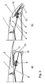
- FIG 1 shows a dropped hinge kinematics as an analogous embodiment of the invention, in which the high-lift flap 2 which is arranged on the mainplane or main wing 1 of the aircraft is mounted on a rotating arm or flap lever 5 such that it can pivot about a rotation point 3 which is provided under the wing 1.
- Figure 3 shows the flap 2 in the retracted position, in which it continues the wing profile continuously essentially without any gap, and in a completely extended position, corresponding to a landing position, with the flap lever 5 not being illustrated in the latter case, in order to improve the clarity.
- a hydraulic actuator can be provided as the actuating drive, and is coupled between the flap lever 5 and a point arranged in a fixed position with respect to the main wing 1.
- the slot 4 between the wing 1 and the flap 2 opens only slowly at the start of the extension movement, because the flap 12 is moving on the said circular arc.
- the high-lift flap 2 is illustrated in three different positions I, II, III.
- the flap 2 In the retracted position I, a cruise flight position, the flap 2 continues the profile of the main wing 1 continuously, essentially without any gap.
- the flap 1 normally has a much greater incidence in the landing position III than in the take-off position II.
- the flap 2 is arranged in a fixed position on the flap lever 5, that is to say it is essentially rigidly connected to it and therefore pivots during extension on a circular path about the rotation point 3, the radius of which circular path is governed by the length of the flap lever 5.
- These positions should be regarded as being only examples, and the kinematics may, of course, also be formed differently.
- the rotation point 3 about which the flap 2 can be pivoted is arranged in a variable position with respect to the main wing 1, in a predetermined manner, specifically essentially on the same plane as the pivoting movement of the flap 2, that is to say on the plane at right angles to the rotation axis which runs through the rotation point, about which the flap 2 can be pivoted by means of the flap lever 5, and may, for example, be provided on a kinematic element 6 which is arranged such that it can move with respect to the main wing 1 and whose position can be varied by means of a drive device, which is not illustrated in its own right in Figure 1 .
- the kinematic element 6 is formed by a lever or an eccentric, which is mounted such that it can rotate about a second rotation point 7, which is arranged in a fixed position with respect to the main wing 1.
- the first rotation point 3 about which the rotating arm or flap lever 5 rotates or pivots, is separated by a predetermined distance from the second rotation point 7.
- the lever or eccentric 6 can be moved about the second rotation point 7 by means of the said drive device, with the first rotation point 3 describing the circular path about the second rotation point 7, as shown in Figure 1 .
- the drive device by means of which the position of the kinematic element 6 can be varied can be operated independently of the actuating drive for the high lift flap 2, or can be operated by being positively coupled to the actuating drive for the flap 2, or to an element which is driven by it.
- the rotation point 3 about which the flap lever 2 is mounted such that it can pivot can be moved by the drive device such that it assumes a first position with respect to the aircraft longitudinal direction x and the aircraft vertical direction 7 when the flap 2 is in the retracted position I, which corresponds to the cruise flight position, in which first position the flap 2 continues the profile of the main wing 1 essentially without any gap and continuously, as is shown in Figure 1 .
- the rotation point 3 assumes a second position which is located forward of the first position with respect to the aircraft longitudinal direction x in the illustrated exemplary embodiment, with the first position being that which the rotation point 3 assumes in the cruise flight position I.
- the rotation point 3 is moved forwards and downwards with respect to the main wing 1, which leads to the slot 4 between the main wing 1 and the flap 2 being enlarged, and to an increase in the flow from the lower face of the main wing 1 to the upper face of the flap, and thus to an increase in the lift.
- the kinematic element 6 is rotated such that the rotation point 2 about which the rotating arm or flap lever 5 pivots assumes a third position which, in the illustrated exemplary embodiment, is located to the rear with respect to the aircraft longitudinal direction x and above, with respect to the aircraft vertical direction z, the second position of the rotation point 3 for the take-off position II.
- the incidence angle of the flap 2 with respect to the main wing 1 is greater, that is to say the flap lever 5 has been rotated through a larger angle from the cruise flight position I than in the case of the take-off position II.
- the flap 2 has been moved further aft and upwards with respect to the main wing 1 than would be the case if the flap 2 were rotated further from the take-off position to the landing position with the position of the rotation point 3 remaining unchanged.
- the kinematic element 6 in the form of the lever or eccentric can be operated by an electrical or hydraulic drive device, or in some other suitable manner.
- the positions of the rotation point 3 which correspond to the various positions I, II, III of the flap 2 and about which the flap 2 can be pivoted on the flap lever 5 lie on a circular path when the kinematic element 6 is embodied in the form of a lever or eccentric, with the centre point of this circular path being formed by the second rotation point 7 of the kinematic element 6. It is possible to move continuously between each of the positions of the rotation point 3 which correspond to the various positions I, II, III of the flap 2, so that the rotation point 3 can be moved from the position which corresponds to the cruise flight position I (retracted flap) via the position which corresponds to the take-off position II (partially extended flap) to the position which corresponds to the landing position III (completely extended flap), and in the opposite direction.
- the method of operation is therefore the same as that for the known flap kinematics.
- a mechanism for operating a Fowler flap in the form of so-called track rear link kinematics is illustrated in figures 3a and 3b .
- a track 8 which extends obliquely downwards to the rear from the wing 1 is provided on the lower face of the wing and a carriage 9 is mounted such that it can move on this track, with the carriage 9 being coupled to a rotation point in the front area of the flap 2 via a first joint 10.
- a lever 13 (rear link) is arranged between a second joint 11, which is located further to the rear on the flap 2, and a third joint 12, which is arranged at the rear end of the track 8, by means of which lever the rear part of the flap is drawn downward in the sense of increasing the incidence angle as the extension movement increases.
- Figure 3a shows the retracted state, corresponding to a cruise flight position, of the flap 2
- Figure 3b shows the completely extended state of the flap 2 corresponding to a landing position.
- this results in relatively quick opening of the slot 4 that is located between the wing 1 and the landing flap 2, by virtue of the inclined position of the track 8 with respect to the aircraft longitudinal direction x, as can be seen from Figure 2a .
- One or more of the joints or rotation points 10, 11 and 12 about which the flap 2 can be pivoted is or are in turn arranged in a variable position, specifically in the case of the rotation point 10 in the sense of an additional relative movement with respect to the track 8 or the wing 1, and in the case of the rotation point 11 in the sense of an additional relative movement between the flap 2 and the lever 13. This additional relative movement is once again carried out essentially on the same plane as the pivoting movement of the flap 2.
- the joint or the rotation point 10, 11, 12 or at least one of the joints or one of the rotation points 10, 11, 12 is or are provided on a corresponding kinematic element which is arranged such that it can move and whose position can be varied by a drive device.
- the kinematic element can, for example, be formed by a lever or an eccentric which - depending on the joint or rotation point 10, 11, 12 at which it is provided - is mounted such that it can rotate about a flap 12 and lever 13 on the carriage 9, on the track 8 or between them.
- the drive device by means of which the position of the kinematic element can be varied, can in turn be operated independently of the actuating drive of the high lift flap 2, or can be operated positively coupled to the actuating drive of the flap 2, or to an element which is driven by it.
- the variability in the position of one or more of the joints or rotation points 10, 11, 12 can therefore in each case be achieved by an additional joint which is coupled via a lever or a crank to the respective variable-position joints or the rotation points 10, 11, 12, in which case the lever or the crank can be moved or pivoted by means of a drive apparatus.
- a guide apparatus can be provided at the respective first variable-position joint, instead of a second joint, by means of which the respective first joint can be positioned, guided by this apparatus.
- the first joint is moved by means of an actuating apparatus to a predetermined position by means of the drive device, which is coupled to the respective variable-position or first joint, so that it is possible to set a predetermined position for the variable-position joint as a function of the set movement position of the flap 2.
- the guide apparatus may have a guide path with which or by means of which the respective variable-position or first joint is guided by means of a drive device in order to vary or move the position of the joint.
- the guide path may be linear or curved, or may be linear and curved in different places.
- the guide path may, in particular, have a circular path at least in places.
- the guide apparatus may also have a coupling device by means of which the respective variable-position joint is mechanically coupled to an associated second joint, which is guided in the movement path, so that the positions of the first joint and of the second joint are positively coupled.
- This coupling device may be a lever, a lever linkage or a transmission which is mounted, or whose position is guided, in an articulated form in the guide path.
- the position of the respective variable-position joint can be varied via a control device with an operating apparatus, with the control device receiving information about the respective position of the flap 2 as an input variable and using this to determine set positions for the respective first joint and, from this, sending an appropriate command to the drive device.
- This command is used to operate the drive device and moves the first joint to an appropriate position by means of the guide apparatus.
- a sensor can be provided in this case, which detects the position of the respective first joint and transmits a value corresponding to this position to the control device, which compares the actual position of the respective first joint with the set position by means of a control function that is implemented in it, and, in the event of any discrepancies between these positions, produced commands to position the respective first joint at its set position.
Abstract
Description
- The invention relates to a high-lift system for an aircraft, according to the precharacterizing clause of Claim 1.
- Documents
WO 2005/021375 A , which shows all the features of the preamble of claim 1,GB-A-2 038 737 EP-A-0 272 396 andDE 103 28 540 A1 disclose a high-lift system for an aircraft having a high-lift flap which can be moved by means of an actuating drive between a retracted position and a plurality of extended positions. The rotation about which the flap can be pivoted is arranged in a variable position with respect to the wing. - Large numbers of high-lift systems for aircraft are known. In general, these comprise high-lift flaps which are arranged on the aircraft main wing and can be moved by means of an actuating drive between a retracted position, in which the flap continuously complements the wing profile essentially without any gap, and a plurality of extended positions, in which a slot of given width is formed between the wing and the flap and the flap is positioned at a predetermined angle with respect to the wing profile. The flap is extended in an entirely general manner in a movement which on the one hand comprises movement of the flap with respect to the wing to the rear, and thus lengthening of the effective wing profile, and on the other hand an increase in the incidence angle of the flap with the profile curvature being increased, thus resulting in an increase in the aerodynamic lift. Air flows at high speed through the slot that is formed between the flap and the wing when in the extended position, from the lower face of the wing to the upper face of the flap, thus making a further contribution to the increase in lift.
- On the one hand, so-called Fowler flaps should be mentioned in particular among the most widely used types of high-lift systems nowadays. In the case of Fowler flaps, while the flap is being extended, it moves backwards away from the wing forming the said slot between the wing and the flap, with an increase in the incidence angle of the flap being superimposed on this movement, particularly as the flap extension increases. This combined movement is also referred to as a Fowler movement.
- On the other hand, an arrangement which is referred to as dropped hinge kinematics or pivoting flap kinematics is known, in which the high-lift flap is mounted on a flap lever such that it can pivot about a rotation point that is provided under the wing. As the name itself implies, the flap is moved about the rotation point, which is located under the wing, during extension, on a path which is in the form of a circular arc.
- The object of the invention is to provide an improved high-lift system.
- This object is achieved by a high-lift system having the features of Claim 1.
- Advantageous embodiments and developments are specified in the dependent claims.
- The invention provides a high-lift system for an aircraft, having a high-lift flap which is arranged on the main wing of the aircraft, is mounted such that it can pivot at one or more rotation points on the wing or on a carriage and can be moved by means of an actuating drive between a retracted position, in which the flap continuously complements the wing profile essentially without any gap, and a plurality of extended positions, in which a slot of the given width is formed between the main wing and the flap, and the flap is positioned at a predetermined angle with respect to the wing profile. According to the invention, the rotation point, about which the flap can be pivoted is arranged in a variable position with respect to the main wing or the carriage or lever which is coupled to the wing.
- According to one embodiment of the invention, the rotation point about which the flap can pivot can be formed by a first joint on a carriage which can be moved on a track which extends obliquely downwards to the rear on the wing.
- The rotation point about which the flap can pivot can be formed by a second joint which is located further to the rear of the flap with respect to the direction of flow of the air flowing around the main wing and is coupled to a third joint, which is arranged on the main wing, via a lever by means of which the rear part of the flap is drawn downwards in the sense of increasing the incidence angle as the extension movement increases.
- The rotation point about which the flap can pivot can be formed by a third joint which is arranged on the wing and by means of which a second joint, which is located in the rear area of the flap is coupled via a lever by means of which the rear part of the flap is drawn downwards in the sense of increasing the incidence angle as the extension movement increases.
- According to one embodiment of the invention, the flap is arranged in a fixed position with respect to the flap lever, and can be pivoted about the rotation point on a circular path.
- According to one embodiment of the high-lift system according to the invention, the rotation point, about which the flap can be pivoted is provided on a kinematic element which is arranged such that it can move with respect to the main wing or with respect to a lever which is coupled to the main wing, and the position of which element can be varied by means of a drive device. The kinematic element is in general a movement apparatus for moving or positioning the rotation point which can be moved as required.
- The kinematic element may be formed by a lever or an eccentric which is mounted such that it can rotate about a second rotation point on the main wing or on the carriage, with the first rotation point about which the flap is mounted such that it can rotate being at a distance from the second rotation point, and with the lever or eccentric being movable about the second rotation point by the drive device.
- The second rotation point may be fixed in position on the main wing.
- According to one embodiment of the high-lift system according to the invention, the drive device by means of which the position of the kinematic element can be varied can be operated independently of the actuating drive for the high-lift flap.
- According to another embodiment, the drive device by means of which the position of the kinematic element can be varied can be operated positively coupled to the actuating drive for the high-lift flap.
- The kinematic element can be operated by an electrical or hydraulic drive device which is coupled to the kinematic element.
- One exemplary embodiment of the invention provides that the rotation point, about which the flap is mounted such that it can pivot, can be moved by the drive device such that the rotation point assumes a first position with respect to the aircraft longitudinal direction and the aircraft vertical direction when the flap is in the retracted position, corresponding to the cruise flight position, in which first position the flap continuously complements the wing profile, essentially without any gap, and assumes a second position, which is located under the first position with respect to the aircraft vertical direction, in a first extended position of the flap, which corresponds to a take-off position.
- In this case, it is possible to provide that, the rotation point, about which the flap lever is mounted such that it can pivot assumes a second position, when the flap is in the first extended position which corresponds to the take-off position, which second position is also located forward of the first position, which corresponds to the cruise flight position, with respect to the aircraft longitudinal direction.
- Furthermore, it is possible to provide that the rotation point, about which the flap is mounted such that it can pivot assumes a third position when the flap is in a second extended position, which corresponds to a landing position, which third position is located aft of the second position with respect to the aircraft longitudinal direction and above the second position, which corresponds to the take-off position, with respect to the aircraft vertical direction.
- According to one embodiment of the high-lift system according to the invention, it is possible to move continuously between the positions of the rotation point which correspond to the various positions of the flap, about which the flap can be pivoted, on a circular path whose centre point forms the second rotation point.
- The invention will be described in the following text with reference to the attached figures, in which:
- ■
Figure 1 shows a schematic side cross-sectional illustration of a high-lift system for an aircraft according to one exemplary embodiment of the invention; - ■
Figure 2a shows a schematic illustration of various phases during the extension movement of flap systems with Track Rear Link Kinematics according to the invention; - ■
Figure 2b shows a schematic illustration of various phases in the extension movement of flap systems with dropped hinged kinematics in the analogous embodiment of the invention according toFigure 1 ; and - ■
Figures 3a and 3b show a side view of a high-lift system for an aircraft according to a further exemplary embodiment of the invention, withFigure 3a showing the exemplary embodiment in the retracted state, andFigure 3b showing the exemplary embodiment in the extended state. -
Figure 1 shows a dropped hinge kinematics as an analogous embodiment of the invention, in which the high-lift flap 2 which is arranged on the mainplane or main wing 1 of the aircraft is mounted on a rotating arm orflap lever 5 such that it can pivot about arotation point 3 which is provided under the wing 1.Figure 3 shows theflap 2 in the retracted position, in which it continues the wing profile continuously essentially without any gap, and in a completely extended position, corresponding to a landing position, with theflap lever 5 not being illustrated in the latter case, in order to improve the clarity. A hydraulic actuator can be provided as the actuating drive, and is coupled between theflap lever 5 and a point arranged in a fixed position with respect to the main wing 1. As shown inFigure 2b , in the case of dropped hinge flap kinematics, theslot 4 between the wing 1 and theflap 2 opens only slowly at the start of the extension movement, because theflap 12 is moving on the said circular arc. - In
Figure 1 , the rotating arm orflap lever 5 on which the high-lift flap 2 is arranged and is mounted such that it can pivot about arotation point 3 which is provided under the main wing 1, is indicated only by means of a simple line. - In the exemplary embodiment shown in
Figure 1 , the high-lift flap 2 is illustrated in three different positions I, II, III. In the retracted position I, a cruise flight position, theflap 2 continues the profile of the main wing 1 continuously, essentially without any gap. In a first extended position II, and in a second extended position III, which respectively form a take-off position and a landing position, theflap 2 is positioned at a predetermined angle with respect to the main wing 1, forming aslot 4 of predetermined width between the main wing 1 and theflap 2. As shown inFigure 1 , the flap 1 normally has a much greater incidence in the landing position III than in the take-off position II. In the exemplary embodiment shown inFigure 1 , theflap 2 is arranged in a fixed position on theflap lever 5, that is to say it is essentially rigidly connected to it and therefore pivots during extension on a circular path about therotation point 3, the radius of which circular path is governed by the length of theflap lever 5. These positions should be regarded as being only examples, and the kinematics may, of course, also be formed differently. - The
rotation point 3 about which theflap 2 can be pivoted is arranged in a variable position with respect to the main wing 1, in a predetermined manner, specifically essentially on the same plane as the pivoting movement of theflap 2, that is to say on the plane at right angles to the rotation axis which runs through the rotation point, about which theflap 2 can be pivoted by means of theflap lever 5, and may, for example, be provided on akinematic element 6 which is arranged such that it can move with respect to the main wing 1 and whose position can be varied by means of a drive device, which is not illustrated in its own right inFigure 1 . In the illustrated exemplary embodiment, thekinematic element 6 is formed by a lever or an eccentric, which is mounted such that it can rotate about asecond rotation point 7, which is arranged in a fixed position with respect to the main wing 1. Thefirst rotation point 3 about which the rotating arm orflap lever 5 rotates or pivots, is separated by a predetermined distance from thesecond rotation point 7. The lever or eccentric 6 can be moved about thesecond rotation point 7 by means of the said drive device, with thefirst rotation point 3 describing the circular path about thesecond rotation point 7, as shown inFigure 1 . - The drive device by means of which the position of the
kinematic element 6 can be varied can be operated independently of the actuating drive for thehigh lift flap 2, or can be operated by being positively coupled to the actuating drive for theflap 2, or to an element which is driven by it. - The
rotation point 3 about which theflap lever 2 is mounted such that it can pivot can be moved by the drive device such that it assumes a first position with respect to the aircraft longitudinal direction x and the aircraftvertical direction 7 when theflap 2 is in the retracted position I, which corresponds to the cruise flight position, in which first position theflap 2 continues the profile of the main wing 1 essentially without any gap and continuously, as is shown inFigure 1 . - In the first, extended position II, as shown in
Figure 1 , which corresponds to the take-off position, therotation point 3 assumes a second position which is located forward of the first position with respect to the aircraft longitudinal direction x in the illustrated exemplary embodiment, with the first position being that which therotation point 3 assumes in the cruise flight position I. In other words, for the take-off position, therotation point 3 is moved forwards and downwards with respect to the main wing 1, which leads to theslot 4 between the main wing 1 and theflap 2 being enlarged, and to an increase in the flow from the lower face of the main wing 1 to the upper face of the flap, and thus to an increase in the lift. - In the third position III of the
flap 2, which is shown inFigure 1 and corresponds to the landing position, thekinematic element 6 is rotated such that therotation point 2 about which the rotating arm orflap lever 5 pivots assumes a third position which, in the illustrated exemplary embodiment, is located to the rear with respect to the aircraft longitudinal direction x and above, with respect to the aircraft vertical direction z, the second position of therotation point 3 for the take-off position II. - In the landing position III, the incidence angle of the
flap 2 with respect to the main wing 1 is greater, that is to say theflap lever 5 has been rotated through a larger angle from the cruise flight position I than in the case of the take-off position II. In the position III, theflap 2 has been moved further aft and upwards with respect to the main wing 1 than would be the case if theflap 2 were rotated further from the take-off position to the landing position with the position of therotation point 3 remaining unchanged. This results in the wing profile being effectively lengthened, with the upper face of theflap 2 being offset less downwards and forwards with respect to the upper face of the main wing 1. - The
kinematic element 6 in the form of the lever or eccentric can be operated by an electrical or hydraulic drive device, or in some other suitable manner. - The positions of the
rotation point 3 which correspond to the various positions I, II, III of theflap 2 and about which theflap 2 can be pivoted on theflap lever 5 lie on a circular path when thekinematic element 6 is embodied in the form of a lever or eccentric, with the centre point of this circular path being formed by thesecond rotation point 7 of thekinematic element 6. It is possible to move continuously between each of the positions of therotation point 3 which correspond to the various positions I, II, III of theflap 2, so that therotation point 3 can be moved from the position which corresponds to the cruise flight position I (retracted flap) via the position which corresponds to the take-off position II (partially extended flap) to the position which corresponds to the landing position III (completely extended flap), and in the opposite direction. The method of operation is therefore the same as that for the known flap kinematics. - A mechanism for operating a Fowler flap in the form of so-called track rear link kinematics according to a exemplary embodiment of the invention is illustrated in
figures 3a and 3b . Atrack 8 which extends obliquely downwards to the rear from the wing 1 is provided on the lower face of the wing and acarriage 9 is mounted such that it can move on this track, with thecarriage 9 being coupled to a rotation point in the front area of theflap 2 via afirst joint 10. A lever 13 (rear link) is arranged between a second joint 11, which is located further to the rear on theflap 2, and a third joint 12, which is arranged at the rear end of thetrack 8, by means of which lever the rear part of the flap is drawn downward in the sense of increasing the incidence angle as the extension movement increases.Figure 3a shows the retracted state, corresponding to a cruise flight position, of theflap 2,Figure 3b shows the completely extended state of theflap 2 corresponding to a landing position. In the case of a Fowler flap such as this, this results in relatively quick opening of theslot 4 that is located between the wing 1 and thelanding flap 2, by virtue of the inclined position of thetrack 8 with respect to the aircraft longitudinal direction x, as can be seen fromFigure 2a . - One or more of the joints or rotation points 10, 11 and 12 about which the
flap 2 can be pivoted is or are in turn arranged in a variable position, specifically in the case of therotation point 10 in the sense of an additional relative movement with respect to thetrack 8 or the wing 1, and in the case of therotation point 11 in the sense of an additional relative movement between theflap 2 and thelever 13. This additional relative movement is once again carried out essentially on the same plane as the pivoting movement of theflap 2. - The joint or the
rotation point Figure 1 , the kinematic element can, for example, be formed by a lever or an eccentric which - depending on the joint orrotation point flap 12 andlever 13 on thecarriage 9, on thetrack 8 or between them. - When the lever or eccentric rotates, the
rotation point - The drive device, by means of which the position of the kinematic element can be varied, can in turn be operated independently of the actuating drive of the
high lift flap 2, or can be operated positively coupled to the actuating drive of theflap 2, or to an element which is driven by it. - The variability in the position of one or more of the joints or rotation points 10, 11, 12 can therefore in each case be achieved by an additional joint which is coupled via a lever or a crank to the respective variable-position joints or the rotation points 10, 11, 12, in which case the lever or the crank can be moved or pivoted by means of a drive apparatus.
- In addition, if an appropriate first joint whose position can be varied is provided in the respective embodiment, a guide apparatus can be provided at the respective first variable-position joint, instead of a second joint, by means of which the respective first joint can be positioned, guided by this apparatus. In this case, the first joint is moved by means of an actuating apparatus to a predetermined position by means of the drive device, which is coupled to the respective variable-position or first joint, so that it is possible to set a predetermined position for the variable-position joint as a function of the set movement position of the
flap 2. The guide apparatus may have a guide path with which or by means of which the respective variable-position or first joint is guided by means of a drive device in order to vary or move the position of the joint. The guide path may be linear or curved, or may be linear and curved in different places. The guide path may, in particular, have a circular path at least in places. However, the guide apparatus may also have a coupling device by means of which the respective variable-position joint is mechanically coupled to an associated second joint, which is guided in the movement path, so that the positions of the first joint and of the second joint are positively coupled. This coupling device may be a lever, a lever linkage or a transmission which is mounted, or whose position is guided, in an articulated form in the guide path. - In particular, if no mechanical coupling is provided between the drive apparatus and a second joint of the guide apparatus in these embodiments, the position of the respective variable-position joint can be varied via a control device with an operating apparatus, with the control device receiving information about the respective position of the
flap 2 as an input variable and using this to determine set positions for the respective first joint and, from this, sending an appropriate command to the drive device. This command is used to operate the drive device and moves the first joint to an appropriate position by means of the guide apparatus. Furthermore, a sensor can be provided in this case, which detects the position of the respective first joint and transmits a value corresponding to this position to the control device, which compares the actual position of the respective first joint with the set position by means of a control function that is implemented in it, and, in the event of any discrepancies between these positions, produced commands to position the respective first joint at its set position. - These embodiments with the guide apparatus with/without a control device can be provided at one or more of the joints in the high-lift system.
-
- 1
- Main wing
- 2
- High-lift flap
- 3
- (first) Rotation point
- 14
- Slot
- 5
- Flap lever
- 6
- Kinematic element
- 7
- Second rotation point
- 8
- Track
- 9
- Carriage
- 10
- Joint
- 11
- Joint
- 12
- Joint
- 13
- Lever
Claims (7)
- High-lift system for an aircraft comprising a main wing (1), a high-lift flap (2) which is coupled to the main wing (1) by a track rear link kinematics comprising a carriage (9) to which the flap is rotationally coupled via a first joint (10), a track (8) for guiding the carriage (9), and a lever (13) which is with a first end connected to the flap via a second joint (11) (2) and with a second end coupled to a rear end of the track (8) via a third joint (12), wherein the flap (2) can be moved by means of an actuating drive between a retracted position (I), in which the flap (2) complements the wing profile, and a plurality of extended positions (II, III), in which a slot (4) of the given width is formed between the wing (1) and the flap (2),
characterized in that
at least one of the joints (10, 11, 12) is provided on a kinematic element (6) for providing an additional joint between the flap (2) and the carriage (9), the first end of the lever (13) or the second end of the lever (13), wherein the kinematic element (6) can be moved by a drive device for varying the position of at least one of the joints (10, 11, 12). - High-lift system for an aircraft according to claim 1, characterized in that the lever (13) is coupled with a first end to the flap (2) via a second joint (11).
- High-lift system for an aircraft according to claim 1, characterized in that the lever (13) is with a first end rigidly connected the flap (2).
- High-lift system for an aircraft according to one of the preceding claims, characterized in that, for adjusting the flap (2), the rotation of the flap lever (5) and the rotation of the kinematic element (6) the high-lift system is arranged such that■ in a retracted and cruise flight position (2a) of the flap in which first position the flap (2) continuously complements the wing profile, essentially without providing a gap, the first rotation point (3) assumes a first position (I) with respect to the aircraft longitudinal direction (x) and the aircraft vertical direction (z),■ in a first extended and take-off position (2b) of the flap (2) the first rotation point (3) assumes a second position (II) which is located under the first position (I) with respect to the aircraft vertical direction (z) and forward of the first position (I) with respect to the aircraft longitudinal direction (x)■ in a second extended and landing position (2c) of the flap (2) the first rotation point (3) assumes a third position (III) which is located aft of the second position (II) with respect to the aircraft longitudinal direction (x) and above the second position (II) with respect to the aircraft vertical direction (z).
- High-lift system for an aircraft according to one of the preceding claims, characterized in that the kinematic element (6) is formed by a lever or an eccentric.
- High-lift system for an aircraft according to one of the preceding claims, characterized in that the drive device and the actuating device can be operated in a coupled manner.
- High-lift system for an aircraft according to one of the preceding claims, characterized in that the drive device and the actuating device can be operated independently.
Applications Claiming Priority (2)
| Application Number | Priority Date | Filing Date | Title |
|---|---|---|---|
| DE102006036464A DE102006036464B4 (en) | 2006-08-04 | 2006-08-04 | High-lift system for an aircraft |
| EP07801527A EP2046650B1 (en) | 2006-08-04 | 2007-08-06 | High-lift system for an aircraft |
Related Parent Applications (1)
| Application Number | Title | Priority Date | Filing Date |
|---|---|---|---|
| EP07801527.8 Division | 2007-08-06 |
Publications (2)
| Publication Number | Publication Date |
|---|---|
| EP2199200A1 EP2199200A1 (en) | 2010-06-23 |
| EP2199200B1 true EP2199200B1 (en) | 2011-10-12 |
Family
ID=38566163
Family Applications (2)
| Application Number | Title | Priority Date | Filing Date |
|---|---|---|---|
| EP10000965A Not-in-force EP2199200B1 (en) | 2006-08-04 | 2007-08-06 | High-lift system for an aircraft |
| EP07801527A Not-in-force EP2046650B1 (en) | 2006-08-04 | 2007-08-06 | High-lift system for an aircraft |
Family Applications After (1)
| Application Number | Title | Priority Date | Filing Date |
|---|---|---|---|
| EP07801527A Not-in-force EP2046650B1 (en) | 2006-08-04 | 2007-08-06 | High-lift system for an aircraft |
Country Status (10)
| Country | Link |
|---|---|
| US (1) | US8302913B2 (en) |
| EP (2) | EP2199200B1 (en) |
| JP (1) | JP2009545478A (en) |
| CN (1) | CN101506050B (en) |
| AT (2) | ATE469025T1 (en) |
| BR (1) | BRPI0714773A2 (en) |
| CA (1) | CA2660094A1 (en) |
| DE (2) | DE102006036464B4 (en) |
| RU (1) | RU2438927C2 (en) |
| WO (1) | WO2008015024A1 (en) |
Families Citing this family (22)
| Publication number | Priority date | Publication date | Assignee | Title |
|---|---|---|---|---|
| DE102006036464B4 (en) | 2006-08-04 | 2009-08-20 | Airbus Deutschland Gmbh | High-lift system for an aircraft |
| DE102006052724B4 (en) * | 2006-11-08 | 2010-03-18 | Liebherr-Aerospace Lindenberg Gmbh | Device for adjusting the curvature of a wing of an aircraft |
| DE102007036996A1 (en) * | 2007-08-06 | 2009-02-19 | Airbus Deutschland Gmbh | High-lift system for an aircraft |
| DE102009015330A1 (en) * | 2009-03-27 | 2010-09-30 | Airbus Deutschland Gmbh | Wing with a high lift flap |
| DE102009015397A1 (en) * | 2009-03-27 | 2010-09-30 | Airbus Deutschland Gmbh | Wing with a high lift flap |
| DE102009002435A1 (en) | 2009-04-16 | 2010-10-21 | Airbus Deutschland Gmbh | A high lift system for an aircraft and method for detecting faults in a high lift system for an aircraft |
| DE102009037707B4 (en) * | 2009-08-17 | 2013-12-24 | Airbus Operations Gmbh | Adjustment mechanism of an adjusting device for coupling an adjustment flap to a main wing and such adjustment |
| US8763953B2 (en) | 2010-07-14 | 2014-07-01 | The Boeing Company | Aircraft flap actuator assembly |
| DE102012111690A1 (en) * | 2012-11-30 | 2014-06-05 | Airbus Operations Gmbh | A variable-shape aerodynamic fairing body for a flap adjustment mechanism of an aircraft |
| EP2746151B1 (en) * | 2012-12-19 | 2017-04-12 | Airbus Operations GmbH | Flap system for an aircraft, method for adjusting the lift of an aircraft and aircraft comprising a main wing and at least one flap system |
| CN103287574B (en) * | 2013-01-05 | 2015-07-01 | 中国航空工业集团公司西安飞机设计研究所 | Control method of high-lift device of airplane |
| US9227720B2 (en) | 2013-03-01 | 2016-01-05 | Roller Bearing Company Of America, Inc. | Composite annular seal assembly for bearings in aircraft |
| CN103332288B (en) * | 2013-06-13 | 2015-05-27 | 西北工业大学 | Edge strip at trailing edge of airplane and design method thereof |
| FR3018767B1 (en) * | 2014-03-21 | 2018-01-12 | Airbus Operations | SUPPORT ASSEMBLY FOR A FLYWHEEL SYSTEM OF AN AIRCRAFT. |
| CN104494843B (en) * | 2014-11-19 | 2017-09-22 | 中国航空工业集团公司沈阳飞机设计研究所 | A kind of aircraft slotted flap design method |
| US10082179B2 (en) | 2014-12-16 | 2018-09-25 | Roller Bearing Company Of America, Inc. | Seal for self aligning roller bearing |
| WO2018005534A1 (en) | 2016-06-30 | 2018-01-04 | Bombardier Inc. | Assemblies and methods for deploying a trailing edge flap of an aircraft |
| BE1024276B1 (en) * | 2016-11-04 | 2018-01-11 | Sonaca Sa | AIRCRAFT WING COMPRISING A MOBILE FLYING LEFT SIDE DRIVEN BY A LINEAR ELECTRIC MOTOR |
| CN108045556B (en) * | 2017-11-30 | 2021-05-25 | 中国航空工业集团公司西安飞机设计研究所 | Airplane flaperon motion mechanism |
| US11091248B2 (en) * | 2019-09-17 | 2021-08-17 | The Boeing Company | Flap actuator mechanism |
| US11548616B1 (en) | 2020-03-02 | 2023-01-10 | Lucas Kai-Luen Hung | Split-flap wing assembly for a high endurance aircraft |
| CN113844640B (en) * | 2021-10-20 | 2023-09-29 | 中航贵州飞机有限责任公司 | Wing trailing edge flap driving structure |
Family Cites Families (20)
| Publication number | Priority date | Publication date | Assignee | Title |
|---|---|---|---|---|
| US2407401A (en) | 1941-09-08 | 1946-09-10 | Douglas Aircraft Co Inc | Lateral control arrangement |
| US3874617A (en) | 1974-07-17 | 1975-04-01 | Mc Donnell Douglas Corp | Stol flaps |
| GB1508389A (en) | 1976-05-03 | 1978-04-26 | Boeing Co | Aerodynamic lift enhancing apparatus |
| US4283029A (en) | 1979-01-02 | 1981-08-11 | Rudolph Peter K C | Actuating apparatus for a flap system having an upper surface blowing powered lift system |
| US4381093A (en) * | 1980-10-07 | 1983-04-26 | The Boeing Company | Flap assembly for aircraft wing |
| US4381082A (en) * | 1980-12-19 | 1983-04-26 | Fmc Corporation | Particulate material handling means |
| US4381092A (en) | 1981-05-01 | 1983-04-26 | Martin Marietta Corporation | Magnetic docking probe for soft docking of space vehicles |
| DE3522448A1 (en) * | 1985-06-22 | 1987-01-02 | Messerschmitt Boelkow Blohm | DRIVE AND GUIDE DEVICE FOR A FLAP ARRANGED ON AN AIRCRAFT WING |
| DE3643808A1 (en) | 1986-12-20 | 1988-06-30 | Dornier Gmbh | DEVICE FOR AERODYNAMICALLY WORKING FLAPS ON AIRCRAFT WINGS, IN PARTICULAR SLIDING FLAPS |
| ES2042279T3 (en) | 1989-02-23 | 1993-12-01 | Zf Friedrichshafen Aktiengesellschaft | DRIVE EQUIPMENT WITH A TORQUE LIMITER. |
| CN2060763U (en) * | 1989-05-21 | 1990-08-22 | 郭朝光 | Ring flank of helicopter |
| DE4107556C1 (en) * | 1991-03-08 | 1992-05-14 | Deutsche Airbus Gmbh, 2000 Hamburg, De | |
| US5788190A (en) * | 1996-10-22 | 1998-08-04 | The Boeing Company | Slotted cruise trailing edge flap |
| DE19732953C1 (en) | 1997-07-31 | 1999-03-11 | Daimler Benz Ag | Wing with flap |
| DE10133920B4 (en) * | 2001-07-12 | 2004-05-13 | Eads Deutschland Gmbh | Lift flap mechanism |
| DE10328540B4 (en) * | 2003-06-24 | 2008-02-14 | Eads Deutschland Gmbh | Actuating device for a rudder flap arranged on the trailing edge of the wing of an aircraft |
| DE10339030B4 (en) | 2003-08-25 | 2005-11-03 | Man Technologie Ag | Support structure for an extendable and retractable flap and its use |
| DE102004006940B4 (en) * | 2004-02-12 | 2009-02-26 | Airbus Deutschland Gmbh | Landing flap guide for aircraft |
| DE102004049504A1 (en) * | 2004-10-11 | 2006-04-13 | Airbus Deutschland Gmbh | Wing for aircraft has a rear auxiliary lift flap coupled to main wing and able to lie against main wing in retracted position and form air gap with it when extended |
| DE102006036464B4 (en) | 2006-08-04 | 2009-08-20 | Airbus Deutschland Gmbh | High-lift system for an aircraft |
-
2006
- 2006-08-04 DE DE102006036464A patent/DE102006036464B4/en not_active Expired - Fee Related
-
2007
- 2007-08-06 DE DE602007006808T patent/DE602007006808D1/en active Active
- 2007-08-06 BR BRPI0714773-2A2A patent/BRPI0714773A2/en not_active IP Right Cessation
- 2007-08-06 EP EP10000965A patent/EP2199200B1/en not_active Not-in-force
- 2007-08-06 AT AT07801527T patent/ATE469025T1/en not_active IP Right Cessation
- 2007-08-06 CA CA002660094A patent/CA2660094A1/en not_active Abandoned
- 2007-08-06 EP EP07801527A patent/EP2046650B1/en not_active Not-in-force
- 2007-08-06 JP JP2009522185A patent/JP2009545478A/en active Pending
- 2007-08-06 RU RU2009107490/11A patent/RU2438927C2/en not_active IP Right Cessation
- 2007-08-06 AT AT10000965T patent/ATE528208T1/en not_active IP Right Cessation
- 2007-08-06 WO PCT/EP2007/006945 patent/WO2008015024A1/en active Application Filing
- 2007-08-06 CN CN2007800286083A patent/CN101506050B/en not_active Expired - Fee Related
- 2007-08-06 US US12/376,258 patent/US8302913B2/en active Active
Also Published As
| Publication number | Publication date |
|---|---|
| RU2438927C2 (en) | 2012-01-10 |
| CN101506050A (en) | 2009-08-12 |
| JP2009545478A (en) | 2009-12-24 |
| US20090308982A1 (en) | 2009-12-17 |
| DE102006036464B4 (en) | 2009-08-20 |
| DE602007006808D1 (en) | 2010-07-08 |
| EP2046650B1 (en) | 2010-05-26 |
| DE102006036464A1 (en) | 2008-02-14 |
| CA2660094A1 (en) | 2008-02-07 |
| WO2008015024A1 (en) | 2008-02-07 |
| BRPI0714773A2 (en) | 2013-10-29 |
| RU2009107490A (en) | 2010-09-10 |
| ATE528208T1 (en) | 2011-10-15 |
| EP2046650A1 (en) | 2009-04-15 |
| US8302913B2 (en) | 2012-11-06 |
| CN101506050B (en) | 2013-01-16 |
| EP2199200A1 (en) | 2010-06-23 |
| ATE469025T1 (en) | 2010-06-15 |
Similar Documents
| Publication | Publication Date | Title |
|---|---|---|
| EP2199200B1 (en) | High-lift system for an aircraft | |
| JP2009545478A5 (en) | ||
| US8844878B2 (en) | High lift system for an aircraft | |
| EP2162352B1 (en) | High lift system on the airfoil of an aircraft | |
| EP2917101B1 (en) | An airplane wing, an airplane and a flap system | |
| US8517314B2 (en) | Actuator arrangement | |
| US7270305B2 (en) | Aircraft leading edge apparatuses and corresponding methods | |
| EP1398269B2 (en) | Method and apparatus for controlling airflow with a leading edge device having a flexible flow surface | |
| EP2125510B1 (en) | Spoiler for an aerodynamic body of an aircraft | |
| EP2274201B1 (en) | Spoiler deployment mechanism | |
| JP2010512274A5 (en) | ||
| US4915327A (en) | Slat actuation and steering | |
| EP3498596A1 (en) | Actuating mechanism for trailing edge flaps and leading edge slats | |
| US4585192A (en) | Leading edge arrangements for aircraft wings | |
| US20200070954A1 (en) | Wing system for an aircraft with a flow body and a cover panel | |
| EP4269233A1 (en) | Wing for an aircraft | |
| EP0422303B1 (en) | Wing trailing edge flaps for aircraft | |
| EP0359481A2 (en) | Fuselage mounted flap drives for wing trailing edge flaps | |
| EP4311766A1 (en) | Wing for an aircraft | |
| EP3453610B1 (en) | Wing assembly with a main wing and a high-lift system | |
| GB2137569A (en) | Leading edge arrangements for aircraft wings | |
| JPH0378319B2 (en) |
Legal Events
| Date | Code | Title | Description |
|---|---|---|---|
| PUAI | Public reference made under article 153(3) epc to a published international application that has entered the european phase |
Free format text: ORIGINAL CODE: 0009012 |
|
| 17P | Request for examination filed |
Effective date: 20100130 |
|
| AC | Divisional application: reference to earlier application |
Ref document number: 2046650 Country of ref document: EP Kind code of ref document: P |
|
| AK | Designated contracting states |
Kind code of ref document: A1 Designated state(s): AT BE BG CH CY CZ DE DK EE ES FI FR GB GR HU IE IS IT LI LT LU LV MC MT NL PL PT RO SE SI SK TR |
|
| GRAP | Despatch of communication of intention to grant a patent |
Free format text: ORIGINAL CODE: EPIDOSNIGR1 |
|
| RIC1 | Information provided on ipc code assigned before grant |
Ipc: B64C 9/16 20060101AFI20110208BHEP |
|
| GRAS | Grant fee paid |
Free format text: ORIGINAL CODE: EPIDOSNIGR3 |
|
| GRAA | (expected) grant |
Free format text: ORIGINAL CODE: 0009210 |
|
| AC | Divisional application: reference to earlier application |
Ref document number: 2046650 Country of ref document: EP Kind code of ref document: P |
|
| AK | Designated contracting states |
Kind code of ref document: B1 Designated state(s): AT BE BG CH CY CZ DE DK EE ES FI FR GB GR HU IE IS IT LI LT LU LV MC MT NL PL PT RO SE SI SK TR |
|
| REG | Reference to a national code |
Ref country code: GB Ref legal event code: FG4D |
|
| REG | Reference to a national code |
Ref country code: CH Ref legal event code: EP |
|
| REG | Reference to a national code |
Ref country code: IE Ref legal event code: FG4D |
|
| REG | Reference to a national code |
Ref country code: DE Ref legal event code: R096 Ref document number: 602007017895 Country of ref document: DE Effective date: 20111215 |
|
| REG | Reference to a national code |
Ref country code: NL Ref legal event code: VDEP Effective date: 20111012 |
|
| LTIE | Lt: invalidation of european patent or patent extension |
Effective date: 20111012 |
|
| REG | Reference to a national code |
Ref country code: AT Ref legal event code: MK05 Ref document number: 528208 Country of ref document: AT Kind code of ref document: T Effective date: 20111012 |
|
| PG25 | Lapsed in a contracting state [announced via postgrant information from national office to epo] |
Ref country code: BE Free format text: LAPSE BECAUSE OF FAILURE TO SUBMIT A TRANSLATION OF THE DESCRIPTION OR TO PAY THE FEE WITHIN THE PRESCRIBED TIME-LIMIT Effective date: 20111012 Ref country code: IS Free format text: LAPSE BECAUSE OF FAILURE TO SUBMIT A TRANSLATION OF THE DESCRIPTION OR TO PAY THE FEE WITHIN THE PRESCRIBED TIME-LIMIT Effective date: 20120212 Ref country code: LT Free format text: LAPSE BECAUSE OF FAILURE TO SUBMIT A TRANSLATION OF THE DESCRIPTION OR TO PAY THE FEE WITHIN THE PRESCRIBED TIME-LIMIT Effective date: 20111012 |
|
| PG25 | Lapsed in a contracting state [announced via postgrant information from national office to epo] |
Ref country code: NL Free format text: LAPSE BECAUSE OF FAILURE TO SUBMIT A TRANSLATION OF THE DESCRIPTION OR TO PAY THE FEE WITHIN THE PRESCRIBED TIME-LIMIT Effective date: 20111012 Ref country code: SE Free format text: LAPSE BECAUSE OF FAILURE TO SUBMIT A TRANSLATION OF THE DESCRIPTION OR TO PAY THE FEE WITHIN THE PRESCRIBED TIME-LIMIT Effective date: 20111012 Ref country code: PT Free format text: LAPSE BECAUSE OF FAILURE TO SUBMIT A TRANSLATION OF THE DESCRIPTION OR TO PAY THE FEE WITHIN THE PRESCRIBED TIME-LIMIT Effective date: 20120213 Ref country code: LV Free format text: LAPSE BECAUSE OF FAILURE TO SUBMIT A TRANSLATION OF THE DESCRIPTION OR TO PAY THE FEE WITHIN THE PRESCRIBED TIME-LIMIT Effective date: 20111012 Ref country code: SI Free format text: LAPSE BECAUSE OF FAILURE TO SUBMIT A TRANSLATION OF THE DESCRIPTION OR TO PAY THE FEE WITHIN THE PRESCRIBED TIME-LIMIT Effective date: 20111012 Ref country code: GR Free format text: LAPSE BECAUSE OF FAILURE TO SUBMIT A TRANSLATION OF THE DESCRIPTION OR TO PAY THE FEE WITHIN THE PRESCRIBED TIME-LIMIT Effective date: 20120113 |
|
| PG25 | Lapsed in a contracting state [announced via postgrant information from national office to epo] |
Ref country code: CY Free format text: LAPSE BECAUSE OF FAILURE TO SUBMIT A TRANSLATION OF THE DESCRIPTION OR TO PAY THE FEE WITHIN THE PRESCRIBED TIME-LIMIT Effective date: 20111012 |
|
| PG25 | Lapsed in a contracting state [announced via postgrant information from national office to epo] |
Ref country code: EE Free format text: LAPSE BECAUSE OF FAILURE TO SUBMIT A TRANSLATION OF THE DESCRIPTION OR TO PAY THE FEE WITHIN THE PRESCRIBED TIME-LIMIT Effective date: 20111012 Ref country code: CZ Free format text: LAPSE BECAUSE OF FAILURE TO SUBMIT A TRANSLATION OF THE DESCRIPTION OR TO PAY THE FEE WITHIN THE PRESCRIBED TIME-LIMIT Effective date: 20111012 Ref country code: DK Free format text: LAPSE BECAUSE OF FAILURE TO SUBMIT A TRANSLATION OF THE DESCRIPTION OR TO PAY THE FEE WITHIN THE PRESCRIBED TIME-LIMIT Effective date: 20111012 Ref country code: BG Free format text: LAPSE BECAUSE OF FAILURE TO SUBMIT A TRANSLATION OF THE DESCRIPTION OR TO PAY THE FEE WITHIN THE PRESCRIBED TIME-LIMIT Effective date: 20120112 Ref country code: SK Free format text: LAPSE BECAUSE OF FAILURE TO SUBMIT A TRANSLATION OF THE DESCRIPTION OR TO PAY THE FEE WITHIN THE PRESCRIBED TIME-LIMIT Effective date: 20111012 |
|
| PLBE | No opposition filed within time limit |
Free format text: ORIGINAL CODE: 0009261 |
|
| STAA | Information on the status of an ep patent application or granted ep patent |
Free format text: STATUS: NO OPPOSITION FILED WITHIN TIME LIMIT |
|
| PG25 | Lapsed in a contracting state [announced via postgrant information from national office to epo] |
Ref country code: PL Free format text: LAPSE BECAUSE OF FAILURE TO SUBMIT A TRANSLATION OF THE DESCRIPTION OR TO PAY THE FEE WITHIN THE PRESCRIBED TIME-LIMIT Effective date: 20111012 Ref country code: RO Free format text: LAPSE BECAUSE OF FAILURE TO SUBMIT A TRANSLATION OF THE DESCRIPTION OR TO PAY THE FEE WITHIN THE PRESCRIBED TIME-LIMIT Effective date: 20111012 Ref country code: IT Free format text: LAPSE BECAUSE OF FAILURE TO SUBMIT A TRANSLATION OF THE DESCRIPTION OR TO PAY THE FEE WITHIN THE PRESCRIBED TIME-LIMIT Effective date: 20111012 |
|
| 26N | No opposition filed |
Effective date: 20120713 |
|
| REG | Reference to a national code |
Ref country code: DE Ref legal event code: R097 Ref document number: 602007017895 Country of ref document: DE Effective date: 20120713 |
|
| PG25 | Lapsed in a contracting state [announced via postgrant information from national office to epo] |
Ref country code: AT Free format text: LAPSE BECAUSE OF FAILURE TO SUBMIT A TRANSLATION OF THE DESCRIPTION OR TO PAY THE FEE WITHIN THE PRESCRIBED TIME-LIMIT Effective date: 20111012 |
|
| REG | Reference to a national code |
Ref country code: CH Ref legal event code: PL |
|
| PG25 | Lapsed in a contracting state [announced via postgrant information from national office to epo] |
Ref country code: MC Free format text: LAPSE BECAUSE OF NON-PAYMENT OF DUE FEES Effective date: 20120831 |
|
| PG25 | Lapsed in a contracting state [announced via postgrant information from national office to epo] |
Ref country code: CH Free format text: LAPSE BECAUSE OF NON-PAYMENT OF DUE FEES Effective date: 20120831 Ref country code: ES Free format text: LAPSE BECAUSE OF FAILURE TO SUBMIT A TRANSLATION OF THE DESCRIPTION OR TO PAY THE FEE WITHIN THE PRESCRIBED TIME-LIMIT Effective date: 20120123 Ref country code: LI Free format text: LAPSE BECAUSE OF NON-PAYMENT OF DUE FEES Effective date: 20120831 |
|
| REG | Reference to a national code |
Ref country code: IE Ref legal event code: MM4A |
|
| PG25 | Lapsed in a contracting state [announced via postgrant information from national office to epo] |
Ref country code: FI Free format text: LAPSE BECAUSE OF FAILURE TO SUBMIT A TRANSLATION OF THE DESCRIPTION OR TO PAY THE FEE WITHIN THE PRESCRIBED TIME-LIMIT Effective date: 20111012 |
|
| PG25 | Lapsed in a contracting state [announced via postgrant information from national office to epo] |
Ref country code: IE Free format text: LAPSE BECAUSE OF NON-PAYMENT OF DUE FEES Effective date: 20120806 |
|
| REG | Reference to a national code |
Ref country code: DE Ref legal event code: R082 Ref document number: 602007017895 Country of ref document: DE Representative=s name: BIRD & BIRD LLP, DE Ref country code: DE Ref legal event code: R082 Ref document number: 602007017895 Country of ref document: DE Representative=s name: UEXKUELL & STOLBERG, DE |
|
| PG25 | Lapsed in a contracting state [announced via postgrant information from national office to epo] |
Ref country code: MT Free format text: LAPSE BECAUSE OF FAILURE TO SUBMIT A TRANSLATION OF THE DESCRIPTION OR TO PAY THE FEE WITHIN THE PRESCRIBED TIME-LIMIT Effective date: 20111012 |
|
| PG25 | Lapsed in a contracting state [announced via postgrant information from national office to epo] |
Ref country code: TR Free format text: LAPSE BECAUSE OF FAILURE TO SUBMIT A TRANSLATION OF THE DESCRIPTION OR TO PAY THE FEE WITHIN THE PRESCRIBED TIME-LIMIT Effective date: 20111012 |
|
| PG25 | Lapsed in a contracting state [announced via postgrant information from national office to epo] |
Ref country code: LU Free format text: LAPSE BECAUSE OF NON-PAYMENT OF DUE FEES Effective date: 20120806 |
|
| PG25 | Lapsed in a contracting state [announced via postgrant information from national office to epo] |
Ref country code: HU Free format text: LAPSE BECAUSE OF FAILURE TO SUBMIT A TRANSLATION OF THE DESCRIPTION OR TO PAY THE FEE WITHIN THE PRESCRIBED TIME-LIMIT Effective date: 20070806 |
|
| REG | Reference to a national code |
Ref country code: DE Ref legal event code: R082 Ref document number: 602007017895 Country of ref document: DE Representative=s name: BIRD & BIRD LLP, DE |
|
| REG | Reference to a national code |
Ref country code: FR Ref legal event code: PLFP Year of fee payment: 10 |
|
| REG | Reference to a national code |
Ref country code: FR Ref legal event code: PLFP Year of fee payment: 11 |
|
| REG | Reference to a national code |
Ref country code: FR Ref legal event code: PLFP Year of fee payment: 12 |
|
| PGFP | Annual fee paid to national office [announced via postgrant information from national office to epo] |
Ref country code: DE Payment date: 20190822 Year of fee payment: 13 Ref country code: FR Payment date: 20190822 Year of fee payment: 13 |
|
| PGFP | Annual fee paid to national office [announced via postgrant information from national office to epo] |
Ref country code: GB Payment date: 20190821 Year of fee payment: 13 |
|
| REG | Reference to a national code |
Ref country code: DE Ref legal event code: R119 Ref document number: 602007017895 Country of ref document: DE |
|
| GBPC | Gb: european patent ceased through non-payment of renewal fee |
Effective date: 20200806 |
|
| PG25 | Lapsed in a contracting state [announced via postgrant information from national office to epo] |
Ref country code: DE Free format text: LAPSE BECAUSE OF NON-PAYMENT OF DUE FEES Effective date: 20210302 Ref country code: FR Free format text: LAPSE BECAUSE OF NON-PAYMENT OF DUE FEES Effective date: 20200831 |
|
| PG25 | Lapsed in a contracting state [announced via postgrant information from national office to epo] |
Ref country code: GB Free format text: LAPSE BECAUSE OF NON-PAYMENT OF DUE FEES Effective date: 20200806 |