EP2199024A1 - Hand-held power tool - Google Patents
Hand-held power tool Download PDFInfo
- Publication number
- EP2199024A1 EP2199024A1 EP08105996A EP08105996A EP2199024A1 EP 2199024 A1 EP2199024 A1 EP 2199024A1 EP 08105996 A EP08105996 A EP 08105996A EP 08105996 A EP08105996 A EP 08105996A EP 2199024 A1 EP2199024 A1 EP 2199024A1
- Authority
- EP
- European Patent Office
- Prior art keywords
- lens
- hand
- held power
- tool
- power tool
- Prior art date
- Legal status (The legal status is an assumption and is not a legal conclusion. Google has not performed a legal analysis and makes no representation as to the accuracy of the status listed.)
- Granted
Links
- 239000000463 material Substances 0.000 claims description 11
- 238000013016 damping Methods 0.000 claims description 8
- 230000008878 coupling Effects 0.000 claims 1
- 238000010168 coupling process Methods 0.000 claims 1
- 238000005859 coupling reaction Methods 0.000 claims 1
- 238000005286 illumination Methods 0.000 description 12
- XLDBTRJKXLKYTC-UHFFFAOYSA-N 2,3,4,4'-tetrachlorobiphenyl Chemical compound C1=CC(Cl)=CC=C1C1=CC=C(Cl)C(Cl)=C1Cl XLDBTRJKXLKYTC-UHFFFAOYSA-N 0.000 description 10
- 230000007246 mechanism Effects 0.000 description 7
- 230000008901 benefit Effects 0.000 description 6
- 229920001971 elastomer Polymers 0.000 description 4
- 230000035939 shock Effects 0.000 description 4
- 230000004888 barrier function Effects 0.000 description 3
- 230000005540 biological transmission Effects 0.000 description 3
- 238000009527 percussion Methods 0.000 description 3
- 229920002943 EPDM rubber Polymers 0.000 description 2
- 238000005452 bending Methods 0.000 description 2
- 238000005553 drilling Methods 0.000 description 2
- 239000000428 dust Substances 0.000 description 2
- 229920000642 polymer Polymers 0.000 description 2
- 230000000717 retained effect Effects 0.000 description 2
- 230000009471 action Effects 0.000 description 1
- 230000004913 activation Effects 0.000 description 1
- 230000000903 blocking effect Effects 0.000 description 1
- 150000001875 compounds Chemical class 0.000 description 1
- 230000009849 deactivation Effects 0.000 description 1
- 230000000694 effects Effects 0.000 description 1
- 239000011810 insulating material Substances 0.000 description 1
- 230000005499 meniscus Effects 0.000 description 1
Images


Classifications
-
- B—PERFORMING OPERATIONS; TRANSPORTING
- B25—HAND TOOLS; PORTABLE POWER-DRIVEN TOOLS; MANIPULATORS
- B25B—TOOLS OR BENCH DEVICES NOT OTHERWISE PROVIDED FOR, FOR FASTENING, CONNECTING, DISENGAGING OR HOLDING
- B25B23/00—Details of, or accessories for, spanners, wrenches, screwdrivers
- B25B23/18—Devices for illuminating the head of the screw or the nut
-
- B—PERFORMING OPERATIONS; TRANSPORTING
- B25—HAND TOOLS; PORTABLE POWER-DRIVEN TOOLS; MANIPULATORS
- B25B—TOOLS OR BENCH DEVICES NOT OTHERWISE PROVIDED FOR, FOR FASTENING, CONNECTING, DISENGAGING OR HOLDING
- B25B21/00—Portable power-driven screw or nut setting or loosening tools; Attachments for drilling apparatus serving the same purpose
- B25B21/02—Portable power-driven screw or nut setting or loosening tools; Attachments for drilling apparatus serving the same purpose with means for imparting impact to screwdriver blade or nut socket
-
- B—PERFORMING OPERATIONS; TRANSPORTING
- B25—HAND TOOLS; PORTABLE POWER-DRIVEN TOOLS; MANIPULATORS
- B25F—COMBINATION OR MULTI-PURPOSE TOOLS NOT OTHERWISE PROVIDED FOR; DETAILS OR COMPONENTS OF PORTABLE POWER-DRIVEN TOOLS NOT PARTICULARLY RELATED TO THE OPERATIONS PERFORMED AND NOT OTHERWISE PROVIDED FOR
- B25F5/00—Details or components of portable power-driven tools not particularly related to the operations performed and not otherwise provided for
- B25F5/02—Construction of casings, bodies or handles
- B25F5/021—Construction of casings, bodies or handles with guiding devices
Definitions
- the present invention relates to means for illuminating the work area of a hand-held power tool. It has become common for hand-held power tools to include integrated illumination means to permit use even under poor lighting conditions. However it is has been challenging from a design standpoint to simultaneously achieve effective illumination of the work area alongside other design goals, since these hand-held tools should also be compact, light, and especially in the case of cordless tools, energy efficient.
- US 2008/0074865 A1 describes incorporating a PCB ring holding multiple LED units into the nose of a drill/driver. But this position presents certain design challenges.
- the illumination area tends to be smaller than with more remotely positioned light sources.
- the tool holder and tool insert may obscure the light sources. If lenses are used, their position close to the work piece subjects them to possible damage from dirt or debris.
- the nose of a tool is more likely to be involved in collisions with other objects such as the work piece itself.
- vibrations are generated by the action of the tool insert. In the case of an impact driver, the impact mechanism is nearby, creating shocks in the tool nose. Such vibrations and shocks may compromise the stability and durability of the illumination assembly. It would be useful to enjoy the advantages of proximity without the corresponding disadvantages.
- a hand-held power which may be, for example, a drill/driver or impact driver.
- the tool is provided with an output shaft rotatable around a tool axis of rotation, a tool housing portion radially disposed relative to said output shaft, an illuminating element for illuminating a work area of the tool, a lens positioned adjacent said illuminating element, and a cover that secures said lens and said illuminating element to said tool housing portion, wherein a portion of the cover is closer to the axis of rotation than the lens is to the axis of rotation.
- the cover can actually wrap around the lens so as to better secure the lens and illuminating element to the nose of the tool.
- the tool housing portion may advantageously protect the illuminating element and lens from the output shaft. Positioning of the tool housing portion in this way provides structural support for the illuminating element and lens while permitting these elements to be moved out radially relative to the axis of rotation in comparison with prior art designs.
- At least a second illuminating element and at least a second lens are further provided.
- Multiple illuminating elements have the advantage that shadows created by nearby aspects of the tool nose are cancelled out. That is, one illuminating element might illuminate a portion of the work piece that is lies in a shadow with respect to another illuminating element.
- each illuminating element is provided with its own lens element to help guide the light rays and protect the illuminating element.
- the illumination will be more uniformly distributed at the work piece. Because it is impossible to position a light directly along the axis of rotation when using an opaque tool insert, the more illuminating elements that are symmetrically distributed about the axis of rotation, the greater the uniformity of the overall illumination pattern.
- the cover it is preferable to form the cover out of a soft flexible material. This will protect the nose of the tool and any lenses from collisions or contact with foreign objects. Furthermore, since the cover is in contact with the lens and in indirect contact with the illuminating elements and their support member, the cover helps to reduce the impact of vibrations generated by the tool insert while using the tool. When an impact driver or other percussion tool is used, the cover can help to absorb some of the shock generated by engagement of the impact or percussion mechanism.
- the cover generally surrounds the axial and radial face of the tool housing, then it is not necessary to use additional elements for securing the cover to the housing, since the cover can achieve a snug fit with these elements. This advantage is even better realized if the cover is made of a flexible material.
- the cover is advantageously positioned to surround each lens element.
- the cover is provided with slots through which the lens elements may transmit light from the illuminating elements.
- at least a portion of the cover is positioned nearer the axis of rotation than the lens or the illuminating element or its support member.
- This configuration ensures that the lens is well secured to the tool, thereby preventing drop out. It also prevents damage to the lens from scratches that might otherwise come from any angle of approach.
- Each slot in the cover preferably makes a snug fit with each lens element so as to protect against entry of dirt and dust.
- each illuminating element is preferably attached to a generally ring-shaped and generally non-flexible, rigid support member.
- the ring-shape ensures that the illuminating elements are equidistant from the axis of rotation.
- the non-flexible nature provides support so that the illuminating elements remain fixed in position even under the stresses of use.
- the support member that holds the illuminating elements - preferably a printed circuit board (PCB) - and the tool housing.
- PCB printed circuit board
- the support member is furthermore made of a flexible material, it might also protect the PCB by absorbing vibrations arising from the tool insert or from the gear transmission or motor. It also serves to dampen shocks that might create stress on the PCB if there is an impact or percussion mechanism in the tool. It is advantageous if the support member is also made of insulating material, since it can then act as a thermal barrier to insulate the PCB and its associated elements against heat generated by the gear transmission and motor.
- the damping member like the support member, is generally ring-shaped.
- the lens is integral with a ring-shaped lens assembly element then a compound element with multiple lens portions can be conveniently formed in one solitary piece.
- this solitary lens assembly is ring shaped.
- the cover will advantageously cover a portion of the lens assembly, so that it and the other ring-shaped elements are well within the tool.
- the lens assembly has a ring shape, then the lens is preferably formed in an arc shape.
- the arc-shaped lens when positioned directly in front of an illuminating element can serve as a light pipe to distribute the light rays and lead them through the cover. It is preferable if the arc length is greater than or equal to 2 times a length of said illuminating element. This still provides portions of lens assembly without lens elements that can be used by the cover to apply pressure to secure the lens assembly.
- the tool housing particularly the portion of the housing in the nose of the tool that is radially disposed relative to the output shaft, is provided with an annular cavity.
- the damping member, support member and illuminating element can be conveniently positioned within the annular cavity.
- the cover wraps around the housing portion, it therefore serves to trap these elements in the annular cavity.
- the tool housing can secure and protect these elements. If at least a portion of the lens is recessed into the annular cavity, it will also receive protection and be better fixed into position by the tool housing.
- the ratio of a diameter of the support member and a diameter of such a tool fitting is greater than or equal to 1.5.
- the illuminating elements are light emitting diode (LED) units.
- LED's have the advantage that a small and power-sparing unit can still give off bright light.
- the nature of LED's is that they are also very damage-resistant, and this is an advantage considering their proximity to the working end of the power tool.
- a hand-held power tool of the sort used for drilling and/or driving is shown in Figs. 1 and 2 . Since these tools are commonplace, aspects of these tools not relevant to the invention, such as a handle, motor and motor housing are not illustrated.
- the tool may be provided either with a power cord for drawing AC power or may incorporate an intrinsic or removable rechargeable DC battery.
- Torque from the motor is transmitted via a pinion gear 12 through a gear transmission 14 to rotate an intermediate shaft 16.
- the illustrated tool is an impact driver, it is provided with a conventional impact mechanism assembly comprising among other things a striker 18, a spring 20 and an anvil 22 for providing high torque impacts.
- Anvil 22 is integral with an output shaft 24 which is provided with a cavity 26 for receiving a tool insert.
- Output shaft 24 rotates around a tool axis of rotation 28 and is provided with a sleeve 30, a spring 32, a locking ball 34 and a retaining ring 36 which together comprise a tool fitting for retaining such tool inserts.
- a striker housing 38 that extends to overlap a gearbox housing 40 (see Fig. 2 ).
- a rotatable collar 42 surrounds gearbox housing 40 for allowing user adjustment to the impact mechanism and/or other functional aspects of the hand-held tool.
- a housing portion 44 that is contiguous with the striker housing 38 but which is forward of the impact mechanism.
- Inner housing subportion 46 of housing portion 44 embraces a bushing 48 that supports output shaft 24.
- annular cavity 52 Extending into an axial face 50 of housing portion 44 is an annular cavity 52 which is coaxial with respect to axis of rotation 28 and rotary shaft 24. In a plane perpendicular to axis of rotation 28, annular cavity 52 is largely sealed off with respect to a radial face 54 extending around the full perimeter of housing portion 44 by distal housing subportion 56 of housing portion 44. However, on the underside of the nose portion 10 is a notch 58 which traverses distal housing subportion 56 in this plane.
- annular printed circuit board (PCB) 60 Seated within annular cavity 52 is an annular printed circuit board (PCB) 60 which serves as a support member for mounting three LED units 62 that act as illuminating elements.
- PCB 60 is by its nature stiff and sturdy and forms a platform for establishing electrical connections (not shown) with the LED units 62 and for connecting via cable 64 to the remaining circuitry of the hand-held power tool (see Fig. 3 ).
- cable 64 extends radially from PCB 60 and passes through notch 58 thereby also serving to maintain the orientation of PCB 60 in annular cavity 52.
- an annular pad 68 may be provided in the space between annular PCB 60 and floor 66 of annular cavity 52.
- Pad 68 serves as a damping means for vibrationally isolating annular PCB 60.
- pad 68 is preferably made of soft, dampening material, such as rubber, elastomeric polymers, elastomeric rubber, ethylene-propylene-diene rubber, or other similar materials. So that it can provide a thermal barrier to insulate PCB 60 from heat, pad 68 is preferably made of a material having low thermal conductivity.
- a transparent ring 70 Positioned in front of the LED units 62 is a transparent ring 70 that has been provided with three lens portions 72 that refract and guide light emitted by the LED units 62. Less or more lens portions 72 may be provided to correspond with the number of LED units 62. So that the work piece will be broadly illuminated, it is preferable if the lens portion 72 is a gently diverging lens as in the illustrated negative meniscus lens. Alternatively the lens portion can be configured to provide gentle convergence of light rays or no bending of light rays at all.
- a transparent element that is positioned near the illuminating element will be considered a "lens" even if there is little or no bending of light rays, such as would be the case if the inner and outer surfaces of the lens had an identical curved shape.
- the pattern of emitted light overlap so that the central portion of the combined pattern is particularly well-illuminated.
- light rays summate near the axis of rotation 28 precisely where a tool insert would contact the work piece.
- the lens may diverge or converge the light rays even more so, whichever is necessary to generate a generally uniform pattern of illumination with light rays concentrated preferably in the center of the pattern.
- Each of the lens portions 72 is arc-shaped and has an arc length 74 significantly greater than the length 76 of LED units 62.
- the ratio of arc length 74 to length 76 is 3 in the preferred embodiment and is any case preferably greater than 2 and creates a light pipe effect which distributes light along the arc shape of each lens portion 72.
- An extension 78 of transparent ring 70 protrudes into notch 58 and therefore helps to orient this part within annular cavity 52.
- PCB 60 nor pad 68 nor ring 70 needs to necessarily take on a full ring shape. They should be arc-shaped so that they can be positioned within annular cavity 52 but could assume, for example, a general horseshoe shape while still providing a platform for orienting multiple LED units 62.
- the ring-shaped elements are preferably significantly larger in diameter than the diameter of the output shaft 24 and the elements, particularly the sleeve 30 which comprise its tool fitting.
- a diameter 80 of PCB 60 is twice as large as a diameter 82 of sleeve 30 (see Fig. 4 ). These dimensions will help determine the nearest point 84 along the axis of rotation 28 which receives unobstructed light emitted from lens portion 72. There is a distance 86 from this point 84 to the end surface 88 of rotary shaft 24 and ideally this distance is less than the length of a typical tool insert.
- this distance 86 is approximately 1.5x the length 90 between end surface 88 and a center of locking ball 34 and approximately 2x the width 92 of the cavity 26.
- point 84 also establishes an angle 94 that is in this example 35 degrees, but is at a minimum preferably greater than 25 degrees.
- cover 96 is symmetrically arranged around axis of rotation 28 and has a minimum diameter that is greater than the diameter of bushing 48 so that bushing 48 is exposed at the front of the nose portion 10. Moving from front to rear, cover 96 extends almost completely around the rest of nose portion 10, generally surrounding axial face 50 and radial face 54 of housing portion 44 as well as approximately one half of the otherwise exposed surface of striker housing 38.
- Cover 96 mates snugly with two protrusions 98 which are provided on transparent ring 70. Because it covers so large a housing surface area, no other specific fastening means are required to secure cover 96 to the hand-held tool other than the fact that it is constructed of a material capable of flexing resiliently to provide a snug fit onto nose portion 10.
- a soft, flexible material also has shock-absorbing qualities which helps protect nose portion 10 against collisions, etc. Therefore, like pad 68, cover 96 is preferably made of soft, dampening material, such as rubber, elastomeric polymers, elastomeric rubber, ethylene-propylene-diene rubber, or other similar materials.
- Slots 100 are provided in cover 96 to provide windows for light to exit through lens portions 72 (see Fig. 4 ).
- Cover 96 retains transparent ring 70 including its lens portions 72 onto housing portion 44 primarily via contact with ring portions 102 of transparent ring 70. Since transparent ring 70 abuts PCB 60 and pad 68, these elements are also retained by cover 96.
- Slots 100 abut the lens portions 72 to maintain a barrier stopping light or dust from entering between cover 96 and lens portions 72.
- base portions 104 have greater width than corresponding lens portions 72 and therefore traverse the full width of annular cavity 52.
- Lens portions 72 have significant axial thickness and act as a light pipe to guide light rays through the axial thickness of cover 96. For maximum light throughput, lens portions 72 are best positioned flush with cover 96. However, so that they are better protected in case of collision with the nose 10 of the tool, it is preferred to position the lens portions 72 somewhat recessed from cover 96. The flexibility of cover 96 permits portions near slots 100 to fold over somewhat and protect the lens portions 72 when contact is made with a foreign object.
- discrete recessed portions 106 of cover 96 that are nearest slots 100 are recessed relative to the rest of cover 96. That is, the majority of cover 96 extends further from the hand-held tool than the limited recessed portions 106.
Abstract
Description
- The present invention relates to means for illuminating the work area of a hand-held power tool. It has become common for hand-held power tools to include integrated illumination means to permit use even under poor lighting conditions. However it is has been challenging from a design standpoint to simultaneously achieve effective illumination of the work area alongside other design goals, since these hand-held tools should also be compact, light, and especially in the case of cordless tools, energy efficient.
- One solution directed towards drilling/driving tools involves positioning small and lightweight LED's as near as possible to the tool insert for illuminating the immediately adjacent work area. For example,
US 2008/0074865 A1 describes incorporating a PCB ring holding multiple LED units into the nose of a drill/driver. But this position presents certain design challenges. The illumination area tends to be smaller than with more remotely positioned light sources. The tool holder and tool insert may obscure the light sources. If lenses are used, their position close to the work piece subjects them to possible damage from dirt or debris. In practice, the nose of a tool is more likely to be involved in collisions with other objects such as the work piece itself. During use, vibrations are generated by the action of the tool insert. In the case of an impact driver, the impact mechanism is nearby, creating shocks in the tool nose. Such vibrations and shocks may compromise the stability and durability of the illumination assembly. It would be useful to enjoy the advantages of proximity without the corresponding disadvantages. - A hand-held power is described which may be, for example, a drill/driver or impact driver. The tool is provided with an output shaft rotatable around a tool axis of rotation, a tool housing portion radially disposed relative to said output shaft, an illuminating element for illuminating a work area of the tool, a lens positioned adjacent said illuminating element, and a cover that secures said lens and said illuminating element to said tool housing portion, wherein a portion of the cover is closer to the axis of rotation than the lens is to the axis of rotation. In such a configuration, the cover can actually wrap around the lens so as to better secure the lens and illuminating element to the nose of the tool.
- If at least a portion of tool housing portion is positioned between said output shaft and said lens, the tool housing portion may advantageously protect the illuminating element and lens from the output shaft. Positioning of the tool housing portion in this way provides structural support for the illuminating element and lens while permitting these elements to be moved out radially relative to the axis of rotation in comparison with prior art designs.
- Preferably at least a second illuminating element and at least a second lens are further provided. Multiple illuminating elements have the advantage that shadows created by nearby aspects of the tool nose are cancelled out. That is, one illuminating element might illuminate a portion of the work piece that is lies in a shadow with respect to another illuminating element. Naturally it is preferable if each illuminating element is provided with its own lens element to help guide the light rays and protect the illuminating element.
- If the multiple illuminating elements and multiple lenses are arranged symmetrically about the axis of rotation, the illumination will be more uniformly distributed at the work piece. Because it is impossible to position a light directly along the axis of rotation when using an opaque tool insert, the more illuminating elements that are symmetrically distributed about the axis of rotation, the greater the uniformity of the overall illumination pattern.
- It is preferable to form the cover out of a soft flexible material. This will protect the nose of the tool and any lenses from collisions or contact with foreign objects. Furthermore, since the cover is in contact with the lens and in indirect contact with the illuminating elements and their support member, the cover helps to reduce the impact of vibrations generated by the tool insert while using the tool. When an impact driver or other percussion tool is used, the cover can help to absorb some of the shock generated by engagement of the impact or percussion mechanism.
- If the cover generally surrounds the axial and radial face of the tool housing, then it is not necessary to use additional elements for securing the cover to the housing, since the cover can achieve a snug fit with these elements. This advantage is even better realized if the cover is made of a flexible material.
- To best protect the lens elements, the cover is advantageously positioned to surround each lens element. Hence the cover is provided with slots through which the lens elements may transmit light from the illuminating elements. In this configuration, at least a portion of the cover is positioned nearer the axis of rotation than the lens or the illuminating element or its support member. This configuration ensures that the lens is well secured to the tool, thereby preventing drop out. It also prevents damage to the lens from scratches that might otherwise come from any angle of approach. Each slot in the cover preferably makes a snug fit with each lens element so as to protect against entry of dirt and dust.
- To support and position each illuminating element, each is preferably attached to a generally ring-shaped and generally non-flexible, rigid support member. The ring-shape ensures that the illuminating elements are equidistant from the axis of rotation. The non-flexible nature provides support so that the illuminating elements remain fixed in position even under the stresses of use.
- It is advantageous to provide a damping member between the support member that holds the illuminating elements - preferably a printed circuit board (PCB) - and the tool housing. When the support member is furthermore made of a flexible material, it might also protect the PCB by absorbing vibrations arising from the tool insert or from the gear transmission or motor. It also serves to dampen shocks that might create stress on the PCB if there is an impact or percussion mechanism in the tool. It is advantageous if the support member is also made of insulating material, since it can then act as a thermal barrier to insulate the PCB and its associated elements against heat generated by the gear transmission and motor.
- For positioning the and better supporting the damping member, it is advantageous if the damping member, like the support member, is generally ring-shaped.
- If the lens is integral with a ring-shaped lens assembly element then a compound element with multiple lens portions can be conveniently formed in one solitary piece. Like the support member and the damping member, it is preferable if this solitary lens assembly is ring shaped. When such a ring shape is provided, the cover will advantageously cover a portion of the lens assembly, so that it and the other ring-shaped elements are well within the tool.
- It is preferable to have a larger lens so as to transmit more light from the illuminating elements. If the lens assembly has a ring shape, then the lens is preferably formed in an arc shape. The arc-shaped lens when positioned directly in front of an illuminating element can serve as a light pipe to distribute the light rays and lead them through the cover. It is preferable if the arc length is greater than or equal to 2 times a length of said illuminating element. This still provides portions of lens assembly without lens elements that can be used by the cover to apply pressure to secure the lens assembly.
- In order to accommodate and protect these ring-shaped elements, it is preferable if the tool housing, particularly the portion of the housing in the nose of the tool that is radially disposed relative to the output shaft, is provided with an annular cavity. Hence during assembly, the damping member, support member and illuminating element can be conveniently positioned within the annular cavity. When the cover wraps around the housing portion, it therefore serves to trap these elements in the annular cavity.
- This has the advantage that the tool housing can secure and protect these elements. If at least a portion of the lens is recessed into the annular cavity, it will also receive protection and be better fixed into position by the tool housing.
- Relative to prior art solutions wherein the illumination elements were provided very near to the tool fitting and the axis of rotation, it is much more advantageous to move the illumination elements further away. This creates an overall larger illumination zone and furthermore reduces the amount of shadows and blocking of the illumination caused by the tool fitting and tool insert. Preferably the ratio of a diameter of the support member and a diameter of such a tool fitting is greater than or equal to 1.5.
- One can determine a nearest point on the axis of rotation that is in a line-of-sight towards the lenses with respect to obstruction from the tool fitting. There is thereby an angle formed between the axis of rotation and said line-of-sight. It is advantageous if this angle is greater than or equal to 25 degrees so that an even larger cone of light arising from the lens is unobstructed. A still larger angle is preferable since a larger angle means that more light from the illuminating element will reach the work piece unobstructed.
- It is preferable if the illuminating elements are light emitting diode (LED) units. LED's have the advantage that a small and power-sparing unit can still give off bright light. The nature of LED's is that they are also very damage-resistant, and this is an advantage considering their proximity to the working end of the power tool.
-
-
Figure 1 is a perspective view of a nose portion of a hand-held power tool according to the present invention. -
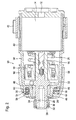
Figure 2 is a section view of a nose portion of a hand-held power tool ofFigure 1 . Certain features are shown in schematic form. -
Figure 3 is a perspective exploded view of a certain subcomponents of one embodiment of the hand-held power tool. -
Figure 4 is a larger version of a portion of the section view ofFigure 2 . - Just the
nose portion 10 of a hand-held power tool of the sort used for drilling and/or driving is shown inFigs. 1 and2 . Since these tools are commonplace, aspects of these tools not relevant to the invention, such as a handle, motor and motor housing are not illustrated. The tool may be provided either with a power cord for drawing AC power or may incorporate an intrinsic or removable rechargeable DC battery. - Torque from the motor is transmitted via a
pinion gear 12 through agear transmission 14 to rotate anintermediate shaft 16. Since the illustrated tool is an impact driver, it is provided with a conventional impact mechanism assembly comprising among other things astriker 18, aspring 20 and an anvil 22 for providing high torque impacts. Anvil 22 is integral with anoutput shaft 24 which is provided with acavity 26 for receiving a tool insert.Output shaft 24 rotates around a tool axis ofrotation 28 and is provided with asleeve 30, aspring 32, a lockingball 34 and a retainingring 36 which together comprise a tool fitting for retaining such tool inserts. - Generally surrounding the impact mechanism is a
striker housing 38 that extends to overlap a gearbox housing 40 (seeFig. 2 ). Arotatable collar 42 surroundsgearbox housing 40 for allowing user adjustment to the impact mechanism and/or other functional aspects of the hand-held tool. There is ahousing portion 44 that is contiguous with thestriker housing 38 but which is forward of the impact mechanism.Inner housing subportion 46 ofhousing portion 44 embraces abushing 48 that supportsoutput shaft 24. - Extending into an
axial face 50 ofhousing portion 44 is anannular cavity 52 which is coaxial with respect to axis ofrotation 28 androtary shaft 24. In a plane perpendicular to axis ofrotation 28,annular cavity 52 is largely sealed off with respect to aradial face 54 extending around the full perimeter ofhousing portion 44 bydistal housing subportion 56 ofhousing portion 44. However, on the underside of thenose portion 10 is anotch 58 which traversesdistal housing subportion 56 in this plane. - Seated within
annular cavity 52 is an annular printed circuit board (PCB) 60 which serves as a support member for mounting threeLED units 62 that act as illuminating elements. As an alternative, two, four, five, six, seven or evenmore LED units 62 may be provided, but they should be arranged symmetrically aroundannular PCB 60. Alternatively only asingle LED unit 62 may be provided. Although it can be arranged in any position, it is preferably positioned on the underside oftool nose 10.PCB 60 is by its nature stiff and sturdy and forms a platform for establishing electrical connections (not shown) with theLED units 62 and for connecting viacable 64 to the remaining circuitry of the hand-held power tool (seeFig. 3 ). Hence viacable 64, the activation and deactivation ofLED units 62 can be achieved.Cable 64 extends radially fromPCB 60 and passes throughnotch 58 thereby also serving to maintain the orientation ofPCB 60 inannular cavity 52. - Optionally but preferably, an
annular pad 68 may be provided in the space betweenannular PCB 60 andfloor 66 ofannular cavity 52.Pad 68 serves as a damping means for vibrationally isolatingannular PCB 60. So that is can absorb vibrations,pad 68 is preferably made of soft, dampening material, such as rubber, elastomeric polymers, elastomeric rubber, ethylene-propylene-diene rubber, or other similar materials. So that it can provide a thermal barrier to insulatePCB 60 from heat,pad 68 is preferably made of a material having low thermal conductivity. - Positioned in front of the
LED units 62 is a transparent ring 70 that has been provided with threelens portions 72 that refract and guide light emitted by theLED units 62. Less ormore lens portions 72 may be provided to correspond with the number ofLED units 62. So that the work piece will be broadly illuminated, it is preferable if thelens portion 72 is a gently diverging lens as in the illustrated negative meniscus lens. Alternatively the lens portion can be configured to provide gentle convergence of light rays or no bending of light rays at all. For the purposes of this description, a transparent element that is positioned near the illuminating element will be considered a "lens" even if there is little or no bending of light rays, such as would be the case if the inner and outer surfaces of the lens had an identical curved shape. - Because there are
multiple LED units 62 andlens portions 72, the pattern of emitted light overlap so that the central portion of the combined pattern is particularly well-illuminated. In other words, light rays summate near the axis ofrotation 28 precisely where a tool insert would contact the work piece. Depending on the source of illumination, it may be preferable for the lens to diverge or converge the light rays even more so, whichever is necessary to generate a generally uniform pattern of illumination with light rays concentrated preferably in the center of the pattern. - Each of the
lens portions 72 is arc-shaped and has anarc length 74 significantly greater than thelength 76 ofLED units 62. The ratio ofarc length 74 tolength 76 is 3 in the preferred embodiment and is any case preferably greater than 2 and creates a light pipe effect which distributes light along the arc shape of eachlens portion 72. Anextension 78 of transparent ring 70 protrudes intonotch 58 and therefore helps to orient this part withinannular cavity 52. - Although it is preferred, neither
PCB 60 norpad 68 nor ring 70 needs to necessarily take on a full ring shape. They should be arc-shaped so that they can be positioned withinannular cavity 52 but could assume, for example, a general horseshoe shape while still providing a platform for orientingmultiple LED units 62. - So that the quantity and quality of the light generated at the work piece by the structure described in the foregoing is improved, the ring-shaped elements are preferably significantly larger in diameter than the diameter of the
output shaft 24 and the elements, particularly thesleeve 30 which comprise its tool fitting. In the preferred embodiment adiameter 80 ofPCB 60 is twice as large as adiameter 82 of sleeve 30 (seeFig. 4 ). These dimensions will help determine thenearest point 84 along the axis ofrotation 28 which receives unobstructed light emitted fromlens portion 72. There is adistance 86 from thispoint 84 to theend surface 88 ofrotary shaft 24 and ideally this distance is less than the length of a typical tool insert. In the preferred embodiment, thisdistance 86 is approximately 1.5x thelength 90 betweenend surface 88 and a center of lockingball 34 and approximately 2x thewidth 92 of thecavity 26. Note thatpoint 84 also establishes anangle 94 that is in this example 35 degrees, but is at a minimum preferably greater than 25 degrees. - The lighting assembly is retained within
annular cavity 52 by acover 96.Cover 96 is symmetrically arranged around axis ofrotation 28 and has a minimum diameter that is greater than the diameter ofbushing 48 so that bushing 48 is exposed at the front of thenose portion 10. Moving from front to rear, cover 96 extends almost completely around the rest ofnose portion 10, generally surroundingaxial face 50 andradial face 54 ofhousing portion 44 as well as approximately one half of the otherwise exposed surface ofstriker housing 38. -
Cover 96 mates snugly with twoprotrusions 98 which are provided on transparent ring 70. Because it covers so large a housing surface area, no other specific fastening means are required to securecover 96 to the hand-held tool other than the fact that it is constructed of a material capable of flexing resiliently to provide a snug fit ontonose portion 10. A soft, flexible material, also has shock-absorbing qualities which helps protectnose portion 10 against collisions, etc. Therefore, likepad 68, cover 96 is preferably made of soft, dampening material, such as rubber, elastomeric polymers, elastomeric rubber, ethylene-propylene-diene rubber, or other similar materials. -
Slots 100 are provided incover 96 to provide windows for light to exit through lens portions 72 (seeFig. 4 ).Cover 96 retains transparent ring 70 including itslens portions 72 ontohousing portion 44 primarily via contact withring portions 102 of transparent ring 70. Since transparent ring 70abuts PCB 60 andpad 68, these elements are also retained bycover 96.Slots 100 abut thelens portions 72 to maintain a barrier stopping light or dust from entering betweencover 96 andlens portions 72. Unlikeslots 100, base portions 104 have greater width than correspondinglens portions 72 and therefore traverse the full width ofannular cavity 52. -
Lens portions 72 have significant axial thickness and act as a light pipe to guide light rays through the axial thickness ofcover 96. For maximum light throughput,lens portions 72 are best positioned flush withcover 96. However, so that they are better protected in case of collision with thenose 10 of the tool, it is preferred to position thelens portions 72 somewhat recessed fromcover 96. The flexibility ofcover 96 permits portions nearslots 100 to fold over somewhat and protect thelens portions 72 when contact is made with a foreign object. - As still a further measure of protection against inadvertent collisions, discrete recessed
portions 106 ofcover 96 that arenearest slots 100 are recessed relative to the rest ofcover 96. That is, the majority ofcover 96 extends further from the hand-held tool than the limited recessedportions 106.
Claims (13)
- A hand-held power tool comprising:an output shaft (26) rotatable around a tool axis of rotation (28);a tool housing portion (44) radially disposed relative to said output shaft (26);an illuminating element (62) for illuminating a work area of the tool;a lens (72) positioned adjacent said illuminating element (62); anda cover (96) that secures said lens (72) and said illuminating element (62) to said tool housing portion (44);characterized in that at least a portion of said cover (96) is closer to the axis of rotation (28) than said lens (72) is to the axis of rotation (28).
- A hand-held power tool according to any one of the preceding claims, characterized in that at least a portion of tool housing portion (44) is positioned between said output shaft (26) and said lens (72).
- A hand-held power tool according to any one of the preceding claims, characterized in that said illuminating element (62) is attached to a rigid support member (60) and a flexible damping member (68) is positioned between said support member (60) and said tool housing portion (44).
- A hand-held power tool according to any one of the preceding claims, characterized in that said housing portion (44) has an annular cavity (52) and said damping member (68), said support member (60), and said illuminating element (62) are positioned within said annular cavity (52).
- A hand-held power tool according to any one of the preceding claims, characterized in that at least a portion of said lens (72) is positioned within said annular cavity (52).
- A hand-held power tool according to any one of the preceding claims, characterized in that said lens (72) is generally arc-shaped.
- A hand-held power tool according to claim 6, characterized in that an arc length (74) of said lens (72) is greater than or equal to 2 times a length (76) of said illuminating element (62).
- A hand-held power tool according to any one of the preceding claims, characterized in that a second illuminating element (62) is provided and a second lens (72) is positioned adjacent said second illuminating element (62).
- A hand-held power tool according to any one of the preceding claims, characterized in that said cover (96) is made of a flexible material.
- A hand-held power tool according to any one of the preceding claims, characterized in that said tool housing portion (44) has an axial face (50) and a radial face (54) and said cover (96) generally surrounds said axial face (50) and said radial face (54).
- A hand-held power tool according to any one of the preceding claims, characterized in that said cover (96) is provided with a slot (100) through which said lens (72) transmits light from said illuminating element (62).
- A hand-held power tool according to any one of the preceding claims, characterized in that a tool fitting (30,32,34,36) is provided for coupling a tool insert to the output shaft (26) and the ratio of a diameter (80) of said support member (60) and a diameter (82) of said tool fitting (30,32,34,36) is greater than or equal to 1.5.
- A hand-held power tool according to any one of the preceding claims, characterized in that there is a point on the axis of rotation (28) having a line-of-sight towards said lens (72) which is nearest to the tool housing portion (44), and an angle (94) formed between the axis of rotation (28) and said line-of-sight is greater than or equal to 25 degrees.
Priority Applications (3)
| Application Number | Priority Date | Filing Date | Title |
|---|---|---|---|
| EP08105996.6A EP2199024B1 (en) | 2008-12-16 | 2008-12-16 | Hand-held power tool |
| US12/638,378 US8496366B2 (en) | 2008-12-16 | 2009-12-15 | Hand-held power tool |
| CN200910253497.7A CN101745664B (en) | 2008-12-16 | 2009-12-16 | Hand-held power tool |
Applications Claiming Priority (1)
| Application Number | Priority Date | Filing Date | Title |
|---|---|---|---|
| EP08105996.6A EP2199024B1 (en) | 2008-12-16 | 2008-12-16 | Hand-held power tool |
Publications (2)
| Publication Number | Publication Date |
|---|---|
| EP2199024A1 true EP2199024A1 (en) | 2010-06-23 |
| EP2199024B1 EP2199024B1 (en) | 2018-09-05 |
Family
ID=40472343
Family Applications (1)
| Application Number | Title | Priority Date | Filing Date |
|---|---|---|---|
| EP08105996.6A Active EP2199024B1 (en) | 2008-12-16 | 2008-12-16 | Hand-held power tool |
Country Status (3)
| Country | Link |
|---|---|
| US (1) | US8496366B2 (en) |
| EP (1) | EP2199024B1 (en) |
| CN (1) | CN101745664B (en) |
Cited By (14)
| Publication number | Priority date | Publication date | Assignee | Title |
|---|---|---|---|---|
| DE102011075663A1 (en) | 2011-05-11 | 2012-11-15 | Robert Bosch Gmbh | Hand-held machine tool i.e. battery-rotary impact screw driver, has lighting unit for section-wise lighting of working field assigned to machine tool during operation and comprising lighting elements, and lens arranged at locking device |
| CN103231350A (en) * | 2013-04-24 | 2013-08-07 | 上海拓步企业发展有限公司 | Electric tool with rotatable multi-lamp lighting structure |
| DE102012205274A1 (en) | 2012-03-30 | 2013-10-02 | Robert Bosch Gmbh | Hand-held machine tool, particularly cordless impact wrench, comprises lighting unit provided at housing for lighting assigned working field in sections, and area by area radiolucent carrier element arranged in area of lighting element |
| US8820955B2 (en) | 2009-02-25 | 2014-09-02 | Black & Decker Inc. | Power tool with light emitting assembly |
| US8827483B2 (en) | 2009-02-25 | 2014-09-09 | Black & Decker Inc. | Light for a power tool and method of illuminating a workpiece |
| EP2691212A4 (en) * | 2011-03-31 | 2015-03-11 | Ingersoll Rand Co | Display assemblies having integrated display covers and light pipes and handheld power tools and methods including same |
| US9028088B2 (en) | 2010-09-30 | 2015-05-12 | Black & Decker Inc. | Lighted power tool |
| WO2015161997A1 (en) * | 2014-04-22 | 2015-10-29 | Atlas Copco Industrial Technique Ab | Indication device for a power tool |
| US9242355B2 (en) | 2012-04-17 | 2016-01-26 | Black & Decker Inc. | Illuminated power tool |
| EP2447006A3 (en) * | 2010-09-30 | 2016-04-20 | Black & Decker Inc. | Power tool with a light for illuminating a workpiece |
| US9328915B2 (en) | 2010-09-30 | 2016-05-03 | Black & Decker Inc. | Lighted power tool |
| US10207380B2 (en) | 2016-12-09 | 2019-02-19 | Black & Decker Inc. | Power tool and light unit |
| EP3715056A1 (en) * | 2019-03-29 | 2020-09-30 | Panasonic Intellectual Property Management Co., Ltd. | Electric power tool |
| DE102014206271B4 (en) | 2014-04-02 | 2024-02-22 | Robert Bosch Gmbh | Hand-held power tool, method for operating a hand-held power tool |
Families Citing this family (18)
| Publication number | Priority date | Publication date | Assignee | Title |
|---|---|---|---|---|
| JP2013119149A (en) * | 2011-12-08 | 2013-06-17 | Makita Corp | Electric power tool |
| CN103009343B (en) * | 2012-11-29 | 2016-04-27 | 南京德朔实业有限公司 | Electric tool |
| CN103256577A (en) * | 2013-05-21 | 2013-08-21 | 苏州华之杰电讯有限公司 | LED lamp of electric tool |
| KR101964103B1 (en) * | 2013-07-05 | 2019-04-01 | 다이슨 테크놀러지 리미티드 | A handheld appliance |
| US10040181B2 (en) * | 2014-03-07 | 2018-08-07 | Chervon (Hk) Limited | Hand-held power tool with lighting element |
| WO2016196984A1 (en) | 2015-06-05 | 2016-12-08 | Ingersoll-Rand Company | Power tools with user-selectable operational modes |
| WO2016196918A1 (en) | 2015-06-05 | 2016-12-08 | Ingersoll-Rand Company | Power tool user interfaces |
| WO2016196905A1 (en) | 2015-06-05 | 2016-12-08 | Ingersoll-Rand Company | Lighting systems for power tools |
| US10668614B2 (en) | 2015-06-05 | 2020-06-02 | Ingersoll-Rand Industrial U.S., Inc. | Impact tools with ring gear alignment features |
| WO2016196899A1 (en) | 2015-06-05 | 2016-12-08 | Ingersoll-Rand Company | Power tool housings |
| WO2016196891A1 (en) | 2015-06-05 | 2016-12-08 | Ingersoll-Rand Company | Power tool user interfaces |
| EP3552727A1 (en) * | 2018-04-08 | 2019-10-16 | Star Co., Ltd. | Drawing-out tool for sheet metal |
| JP2021112816A (en) * | 2020-01-20 | 2021-08-05 | 株式会社マキタ | Electric work machine, lighting attachment, and method for emitting light from electric work machine |
| US11772245B2 (en) * | 2020-02-24 | 2023-10-03 | Milwaukee Electric Tool Corporation | Impact tool |
| US20210260734A1 (en) * | 2020-02-24 | 2021-08-26 | Milwaukee Electric Tool Corporation | Impact tool |
| US11213937B1 (en) | 2020-09-22 | 2022-01-04 | Snap-On Incorporated | Tool illumination source |
| JP2022187761A (en) * | 2021-06-08 | 2022-12-20 | 株式会社マキタ | Electric tool |
| JP2023167146A (en) * | 2022-05-11 | 2023-11-24 | 株式会社マキタ | Power tool |
Citations (6)
| Publication number | Priority date | Publication date | Assignee | Title |
|---|---|---|---|---|
| EP1477282A1 (en) * | 2002-01-21 | 2004-11-17 | Hitachi Koki Co., Ltd. | Power tool |
| US20040264178A1 (en) * | 2003-05-13 | 2004-12-30 | Mobiletron Electronic Co., Ltd. | Screwdriver with light device |
| DE202005021270U1 (en) * | 2005-05-04 | 2007-07-12 | Robert Bosch Gmbh | Hand tool with working field lighting |
| EP1882553A2 (en) * | 2006-07-26 | 2008-01-30 | Hitachi Koki Co., Ltd. | Power tool equiped with light |
| US20080074865A1 (en) * | 2006-09-25 | 2008-03-27 | Manfred Lutz | Hand-held power tool |
| WO2008133339A1 (en) * | 2007-04-23 | 2008-11-06 | Hitachi Koki Co., Ltd. | Electrical power tool |
Family Cites Families (4)
| Publication number | Priority date | Publication date | Assignee | Title |
|---|---|---|---|---|
| US4078869A (en) * | 1977-01-17 | 1978-03-14 | Honeycutt Damon P | Two-way right angle drill |
| US4283757A (en) * | 1979-07-09 | 1981-08-11 | Tweezer-Lite, Inc. | Illuminated screwdriver |
| US20050132589A1 (en) * | 2003-12-22 | 2005-06-23 | Johnson Robert F. | Visual alignment aid for handheld tools |
| DE102005021383A1 (en) * | 2005-05-04 | 2006-11-09 | Robert Bosch Gmbh | Rechargeable battery-electric hand tool machine, has LED diode utilized as light source, which switches on light system, where light of diode is erected on operating field, and diode and light control system are arranged in light pipe |
-
2008
- 2008-12-16 EP EP08105996.6A patent/EP2199024B1/en active Active
-
2009
- 2009-12-15 US US12/638,378 patent/US8496366B2/en active Active
- 2009-12-16 CN CN200910253497.7A patent/CN101745664B/en active Active
Patent Citations (6)
| Publication number | Priority date | Publication date | Assignee | Title |
|---|---|---|---|---|
| EP1477282A1 (en) * | 2002-01-21 | 2004-11-17 | Hitachi Koki Co., Ltd. | Power tool |
| US20040264178A1 (en) * | 2003-05-13 | 2004-12-30 | Mobiletron Electronic Co., Ltd. | Screwdriver with light device |
| DE202005021270U1 (en) * | 2005-05-04 | 2007-07-12 | Robert Bosch Gmbh | Hand tool with working field lighting |
| EP1882553A2 (en) * | 2006-07-26 | 2008-01-30 | Hitachi Koki Co., Ltd. | Power tool equiped with light |
| US20080074865A1 (en) * | 2006-09-25 | 2008-03-27 | Manfred Lutz | Hand-held power tool |
| WO2008133339A1 (en) * | 2007-04-23 | 2008-11-06 | Hitachi Koki Co., Ltd. | Electrical power tool |
Cited By (21)
| Publication number | Priority date | Publication date | Assignee | Title |
|---|---|---|---|---|
| US8820955B2 (en) | 2009-02-25 | 2014-09-02 | Black & Decker Inc. | Power tool with light emitting assembly |
| US8827483B2 (en) | 2009-02-25 | 2014-09-09 | Black & Decker Inc. | Light for a power tool and method of illuminating a workpiece |
| US9352458B2 (en) | 2009-02-25 | 2016-05-31 | Black & Decker Inc. | Power tool with light for illuminating workpiece |
| EP2447006A3 (en) * | 2010-09-30 | 2016-04-20 | Black & Decker Inc. | Power tool with a light for illuminating a workpiece |
| US11090786B2 (en) | 2010-09-30 | 2021-08-17 | Black & Decker Inc. | Lighted power tool |
| US10543588B2 (en) | 2010-09-30 | 2020-01-28 | Black & Decker Inc. | Lighted power tool |
| US9644837B2 (en) | 2010-09-30 | 2017-05-09 | Black & Decker Inc. | Lighted power tool |
| US9028088B2 (en) | 2010-09-30 | 2015-05-12 | Black & Decker Inc. | Lighted power tool |
| US9328915B2 (en) | 2010-09-30 | 2016-05-03 | Black & Decker Inc. | Lighted power tool |
| EP2691212A4 (en) * | 2011-03-31 | 2015-03-11 | Ingersoll Rand Co | Display assemblies having integrated display covers and light pipes and handheld power tools and methods including same |
| US10058989B2 (en) | 2011-03-31 | 2018-08-28 | Ingersoll-Rand Company | Display assemblies having integrated display covers and light pipes and handheld power tools and methods including same |
| DE102011075663A1 (en) | 2011-05-11 | 2012-11-15 | Robert Bosch Gmbh | Hand-held machine tool i.e. battery-rotary impact screw driver, has lighting unit for section-wise lighting of working field assigned to machine tool during operation and comprising lighting elements, and lens arranged at locking device |
| DE102012205274A1 (en) | 2012-03-30 | 2013-10-02 | Robert Bosch Gmbh | Hand-held machine tool, particularly cordless impact wrench, comprises lighting unit provided at housing for lighting assigned working field in sections, and area by area radiolucent carrier element arranged in area of lighting element |
| US9242355B2 (en) | 2012-04-17 | 2016-01-26 | Black & Decker Inc. | Illuminated power tool |
| US10173307B2 (en) | 2012-04-17 | 2019-01-08 | Black & Decker Inc. | Illuminated power tool |
| CN103231350A (en) * | 2013-04-24 | 2013-08-07 | 上海拓步企业发展有限公司 | Electric tool with rotatable multi-lamp lighting structure |
| DE102014206271B4 (en) | 2014-04-02 | 2024-02-22 | Robert Bosch Gmbh | Hand-held power tool, method for operating a hand-held power tool |
| WO2015161997A1 (en) * | 2014-04-22 | 2015-10-29 | Atlas Copco Industrial Technique Ab | Indication device for a power tool |
| KR20160146871A (en) * | 2014-04-22 | 2016-12-21 | 아틀라스 콥코 인더스트리얼 테크니크 에이비 | Indication device for a power tool |
| US10207380B2 (en) | 2016-12-09 | 2019-02-19 | Black & Decker Inc. | Power tool and light unit |
| EP3715056A1 (en) * | 2019-03-29 | 2020-09-30 | Panasonic Intellectual Property Management Co., Ltd. | Electric power tool |
Also Published As
| Publication number | Publication date |
|---|---|
| CN101745664A (en) | 2010-06-23 |
| CN101745664B (en) | 2014-12-31 |
| EP2199024B1 (en) | 2018-09-05 |
| US20100149790A1 (en) | 2010-06-17 |
| US8496366B2 (en) | 2013-07-30 |
Similar Documents
| Publication | Publication Date | Title |
|---|---|---|
| EP2199024B1 (en) | Hand-held power tool | |
| US10821595B2 (en) | Power tool | |
| US20110058356A1 (en) | Power tool with light emitting assembly | |
| US20060262519A1 (en) | Power tool with work field illumination | |
| US10099341B2 (en) | Power tool | |
| US9481081B2 (en) | Power tool having a work field lighting system | |
| EP1658932A1 (en) | Power tool with illumination device | |
| US8851698B2 (en) | Articulation drill with illumination | |
| EP1001866B1 (en) | Illumination for power tools | |
| US20040016082A1 (en) | Power tool with at least one handle | |
| US7137761B2 (en) | Right angle drill with an improved structure for accommodating a light assembly | |
| US7204744B2 (en) | Hand-operated machine-tool comprising a vibration-damping rotary handle | |
| CA2594441A1 (en) | Power tool equipped with light | |
| EP3386683B1 (en) | Rotary power tool lighting system | |
| US20050047878A1 (en) | Tool chuck having a light transmitting capability | |
| US20180222032A1 (en) | Shock Absorbing Protection Structure for Handheld Power Tool | |
| US20140190716A1 (en) | Electric power tool | |
| JP2007175833A (en) | Power tool | |
| US6712368B2 (en) | Quick attachment release system for a rotary hand tool | |
| US20090168434A1 (en) | Illuminating Device | |
| US20220388141A1 (en) | Power tool | |
| JP4923883B2 (en) | Electric tool | |
| US20140270908A1 (en) | Adapter for Connecting an Auxiliary Handle to a Hand-Held Power Tool | |
| GB2467307A (en) | Device for producing an air current and light | |
| CN112824745B (en) | Hand tool and lighting fixture support for connecting with hand tool |
Legal Events
| Date | Code | Title | Description |
|---|---|---|---|
| PUAI | Public reference made under article 153(3) epc to a published international application that has entered the european phase |
Free format text: ORIGINAL CODE: 0009012 |
|
| AK | Designated contracting states |
Kind code of ref document: A1 Designated state(s): AT BE BG CH CY CZ DE DK EE ES FI FR GB GR HR HU IE IS IT LI LT LU LV MC MT NL NO PL PT RO SE SI SK TR |
|
| AX | Request for extension of the european patent |
Extension state: AL BA MK RS |
|
| 17P | Request for examination filed |
Effective date: 20101223 |
|
| AKX | Designation fees paid |
Designated state(s): DE GB |
|
| 17Q | First examination report despatched |
Effective date: 20110412 |
|
| REG | Reference to a national code |
Ref country code: DE Ref legal event code: R079 Ref document number: 602008056781 Country of ref document: DE Free format text: PREVIOUS MAIN CLASS: B25B0023180000 Ipc: B25B0021020000 |
|
| GRAP | Despatch of communication of intention to grant a patent |
Free format text: ORIGINAL CODE: EPIDOSNIGR1 |
|
| RIC1 | Information provided on ipc code assigned before grant |
Ipc: B25B 21/02 20060101AFI20180321BHEP Ipc: B25F 5/02 20060101ALI20180321BHEP Ipc: B25B 23/18 20060101ALI20180321BHEP |
|
| INTG | Intention to grant announced |
Effective date: 20180409 |
|
| RIN1 | Information on inventor provided before grant (corrected) |
Inventor name: LEONG, CHI HOE |
|
| GRAS | Grant fee paid |
Free format text: ORIGINAL CODE: EPIDOSNIGR3 |
|
| GRAA | (expected) grant |
Free format text: ORIGINAL CODE: 0009210 |
|
| AK | Designated contracting states |
Kind code of ref document: B1 Designated state(s): DE GB |
|
| REG | Reference to a national code |
Ref country code: GB Ref legal event code: FG4D |
|
| REG | Reference to a national code |
Ref country code: DE Ref legal event code: R096 Ref document number: 602008056781 Country of ref document: DE |
|
| REG | Reference to a national code |
Ref country code: DE Ref legal event code: R097 Ref document number: 602008056781 Country of ref document: DE |
|
| PLBE | No opposition filed within time limit |
Free format text: ORIGINAL CODE: 0009261 |
|
| STAA | Information on the status of an ep patent application or granted ep patent |
Free format text: STATUS: NO OPPOSITION FILED WITHIN TIME LIMIT |
|
| 26N | No opposition filed |
Effective date: 20190606 |
|
| PGFP | Annual fee paid to national office [announced via postgrant information from national office to epo] |
Ref country code: GB Payment date: 20221222 Year of fee payment: 15 |
|
| PGFP | Annual fee paid to national office [announced via postgrant information from national office to epo] |
Ref country code: DE Payment date: 20230223 Year of fee payment: 15 |