EP2198967A2 - DNA-array-equipped cartridge,analyzer and method for using the dna-array-equipped cartridge - Google Patents
DNA-array-equipped cartridge,analyzer and method for using the dna-array-equipped cartridge Download PDFInfo
- Publication number
- EP2198967A2 EP2198967A2 EP09252659A EP09252659A EP2198967A2 EP 2198967 A2 EP2198967 A2 EP 2198967A2 EP 09252659 A EP09252659 A EP 09252659A EP 09252659 A EP09252659 A EP 09252659A EP 2198967 A2 EP2198967 A2 EP 2198967A2
- Authority
- EP
- European Patent Office
- Prior art keywords
- dna
- array
- reaction tank
- housing
- light
- Prior art date
- Legal status (The legal status is an assumption and is not a legal conclusion. Google has not performed a legal analysis and makes no representation as to the accuracy of the status listed.)
- Withdrawn
Links
- 238000000034 method Methods 0.000 title claims description 25
- 238000006243 chemical reaction Methods 0.000 claims abstract description 243
- 239000003298 DNA probe Substances 0.000 claims abstract description 122
- 239000012530 fluid Substances 0.000 claims abstract description 45
- 239000007788 liquid Substances 0.000 claims description 194
- 239000002699 waste material Substances 0.000 claims description 52
- 108020003215 DNA Probes Proteins 0.000 claims description 25
- 239000003153 chemical reaction reagent Substances 0.000 claims description 20
- 238000002360 preparation method Methods 0.000 claims description 15
- OKTJSMMVPCPJKN-UHFFFAOYSA-N Carbon Chemical compound [C] OKTJSMMVPCPJKN-UHFFFAOYSA-N 0.000 claims description 7
- 229910052799 carbon Inorganic materials 0.000 claims description 7
- 229910052751 metal Inorganic materials 0.000 claims description 7
- 239000002184 metal Substances 0.000 claims description 7
- 239000011347 resin Substances 0.000 claims description 7
- 229920005989 resin Polymers 0.000 claims description 7
- 238000000746 purification Methods 0.000 claims description 3
- 239000000523 sample Substances 0.000 claims description 3
- 238000009792 diffusion process Methods 0.000 description 22
- 238000010586 diagram Methods 0.000 description 21
- 239000011259 mixed solution Substances 0.000 description 19
- 238000001514 detection method Methods 0.000 description 17
- 239000013307 optical fiber Substances 0.000 description 16
- 239000012149 elution buffer Substances 0.000 description 13
- 238000002347 injection Methods 0.000 description 11
- 239000007924 injection Substances 0.000 description 11
- 230000019612 pigmentation Effects 0.000 description 11
- 238000003756 stirring Methods 0.000 description 11
- 241000209094 Oryza Species 0.000 description 9
- 235000007164 Oryza sativa Nutrition 0.000 description 9
- 238000012545 processing Methods 0.000 description 9
- 235000009566 rice Nutrition 0.000 description 9
- 238000009396 hybridization Methods 0.000 description 8
- 230000023077 detection of light stimulus Effects 0.000 description 6
- 239000000463 material Substances 0.000 description 6
- 241000894007 species Species 0.000 description 6
- 239000007795 chemical reaction product Substances 0.000 description 5
- 238000011049 filling Methods 0.000 description 5
- 238000012856 packing Methods 0.000 description 5
- 239000011534 wash buffer Substances 0.000 description 5
- PXHVJJICTQNCMI-UHFFFAOYSA-N Nickel Chemical compound [Ni] PXHVJJICTQNCMI-UHFFFAOYSA-N 0.000 description 4
- 239000000853 adhesive Substances 0.000 description 4
- 230000001070 adhesive effect Effects 0.000 description 4
- 238000012937 correction Methods 0.000 description 4
- 239000000243 solution Substances 0.000 description 4
- 238000005406 washing Methods 0.000 description 4
- 239000004809 Teflon Substances 0.000 description 3
- 229920006362 Teflon® Polymers 0.000 description 3
- 239000002518 antifoaming agent Substances 0.000 description 3
- 230000001105 regulatory effect Effects 0.000 description 3
- RYGMFSIKBFXOCR-UHFFFAOYSA-N Copper Chemical compound [Cu] RYGMFSIKBFXOCR-UHFFFAOYSA-N 0.000 description 2
- YCKRFDGAMUMZLT-UHFFFAOYSA-N Fluorine atom Chemical compound [F] YCKRFDGAMUMZLT-UHFFFAOYSA-N 0.000 description 2
- 229910052782 aluminium Inorganic materials 0.000 description 2
- XAGFODPZIPBFFR-UHFFFAOYSA-N aluminium Chemical compound [Al] XAGFODPZIPBFFR-UHFFFAOYSA-N 0.000 description 2
- BFNBIHQBYMNNAN-UHFFFAOYSA-N ammonium sulfate Chemical compound N.N.OS(O)(=O)=O BFNBIHQBYMNNAN-UHFFFAOYSA-N 0.000 description 2
- 229910052921 ammonium sulfate Inorganic materials 0.000 description 2
- 235000011130 ammonium sulphate Nutrition 0.000 description 2
- 229910052802 copper Inorganic materials 0.000 description 2
- 239000010949 copper Substances 0.000 description 2
- 230000003247 decreasing effect Effects 0.000 description 2
- 238000007599 discharging Methods 0.000 description 2
- 229910052731 fluorine Inorganic materials 0.000 description 2
- 239000011737 fluorine Substances 0.000 description 2
- 239000007789 gas Substances 0.000 description 2
- 229910052759 nickel Inorganic materials 0.000 description 2
- 238000007747 plating Methods 0.000 description 2
- 239000004417 polycarbonate Substances 0.000 description 2
- 229920000515 polycarbonate Polymers 0.000 description 2
- 238000011084 recovery Methods 0.000 description 2
- XLYOFNOQVPJJNP-UHFFFAOYSA-N water Substances O XLYOFNOQVPJJNP-UHFFFAOYSA-N 0.000 description 2
- 229920000089 Cyclic olefin copolymer Polymers 0.000 description 1
- 241000219470 Mirabilis Species 0.000 description 1
- 239000004743 Polypropylene Substances 0.000 description 1
- VYPSYNLAJGMNEJ-UHFFFAOYSA-N Silicium dioxide Chemical compound O=[Si]=O VYPSYNLAJGMNEJ-UHFFFAOYSA-N 0.000 description 1
- 230000003321 amplification Effects 0.000 description 1
- 238000005452 bending Methods 0.000 description 1
- 239000000872 buffer Substances 0.000 description 1
- 239000000919 ceramic Substances 0.000 description 1
- 150000001925 cycloalkenes Chemical class 0.000 description 1
- 238000013461 design Methods 0.000 description 1
- 239000012153 distilled water Substances 0.000 description 1
- PEZBJHXXIFFJBI-UHFFFAOYSA-N ethanol;phosphoric acid Chemical compound CCO.OP(O)(O)=O PEZBJHXXIFFJBI-UHFFFAOYSA-N 0.000 description 1
- 239000006260 foam Substances 0.000 description 1
- 238000005187 foaming Methods 0.000 description 1
- IXCSERBJSXMMFS-UHFFFAOYSA-N hydrogen chloride Substances Cl.Cl IXCSERBJSXMMFS-UHFFFAOYSA-N 0.000 description 1
- 229910000041 hydrogen chloride Inorganic materials 0.000 description 1
- 238000009413 insulation Methods 0.000 description 1
- 238000002156 mixing Methods 0.000 description 1
- 239000000203 mixture Substances 0.000 description 1
- 238000003199 nucleic acid amplification method Methods 0.000 description 1
- 239000004033 plastic Substances 0.000 description 1
- -1 polypropylene Polymers 0.000 description 1
- 229920001155 polypropylene Polymers 0.000 description 1
- 238000001556 precipitation Methods 0.000 description 1
- 238000007639 printing Methods 0.000 description 1
- 239000000047 product Substances 0.000 description 1
- 239000011541 reaction mixture Substances 0.000 description 1
- 230000004044 response Effects 0.000 description 1
- 150000003839 salts Chemical class 0.000 description 1
- 239000000741 silica gel Substances 0.000 description 1
- 229910002027 silica gel Inorganic materials 0.000 description 1
- 238000001179 sorption measurement Methods 0.000 description 1
- 238000005507 spraying Methods 0.000 description 1
- 239000000758 substrate Substances 0.000 description 1
- 230000000007 visual effect Effects 0.000 description 1
Images








Classifications
-
- B—PERFORMING OPERATIONS; TRANSPORTING
- B01—PHYSICAL OR CHEMICAL PROCESSES OR APPARATUS IN GENERAL
- B01L—CHEMICAL OR PHYSICAL LABORATORY APPARATUS FOR GENERAL USE
- B01L3/00—Containers or dishes for laboratory use, e.g. laboratory glassware; Droppers
- B01L3/50—Containers for the purpose of retaining a material to be analysed, e.g. test tubes
- B01L3/502—Containers for the purpose of retaining a material to be analysed, e.g. test tubes with fluid transport, e.g. in multi-compartment structures
-
- B—PERFORMING OPERATIONS; TRANSPORTING
- B01—PHYSICAL OR CHEMICAL PROCESSES OR APPARATUS IN GENERAL
- B01L—CHEMICAL OR PHYSICAL LABORATORY APPARATUS FOR GENERAL USE
- B01L2300/00—Additional constructional details
- B01L2300/06—Auxiliary integrated devices, integrated components
- B01L2300/0627—Sensor or part of a sensor is integrated
- B01L2300/0636—Integrated biosensor, microarrays
-
- B—PERFORMING OPERATIONS; TRANSPORTING
- B01—PHYSICAL OR CHEMICAL PROCESSES OR APPARATUS IN GENERAL
- B01L—CHEMICAL OR PHYSICAL LABORATORY APPARATUS FOR GENERAL USE
- B01L2300/00—Additional constructional details
- B01L2300/06—Auxiliary integrated devices, integrated components
- B01L2300/0627—Sensor or part of a sensor is integrated
- B01L2300/0654—Lenses; Optical fibres
-
- B—PERFORMING OPERATIONS; TRANSPORTING
- B01—PHYSICAL OR CHEMICAL PROCESSES OR APPARATUS IN GENERAL
- B01L—CHEMICAL OR PHYSICAL LABORATORY APPARATUS FOR GENERAL USE
- B01L2300/00—Additional constructional details
- B01L2300/08—Geometry, shape and general structure
- B01L2300/0803—Disc shape
-
- B—PERFORMING OPERATIONS; TRANSPORTING
- B01—PHYSICAL OR CHEMICAL PROCESSES OR APPARATUS IN GENERAL
- B01L—CHEMICAL OR PHYSICAL LABORATORY APPARATUS FOR GENERAL USE
- B01L2300/00—Additional constructional details
- B01L2300/08—Geometry, shape and general structure
- B01L2300/0861—Configuration of multiple channels and/or chambers in a single devices
-
- B—PERFORMING OPERATIONS; TRANSPORTING
- B01—PHYSICAL OR CHEMICAL PROCESSES OR APPARATUS IN GENERAL
- B01L—CHEMICAL OR PHYSICAL LABORATORY APPARATUS FOR GENERAL USE
- B01L2300/00—Additional constructional details
- B01L2300/08—Geometry, shape and general structure
- B01L2300/0861—Configuration of multiple channels and/or chambers in a single devices
- B01L2300/0867—Multiple inlets and one sample wells, e.g. mixing, dilution
-
- B—PERFORMING OPERATIONS; TRANSPORTING
- B01—PHYSICAL OR CHEMICAL PROCESSES OR APPARATUS IN GENERAL
- B01L—CHEMICAL OR PHYSICAL LABORATORY APPARATUS FOR GENERAL USE
- B01L2300/00—Additional constructional details
- B01L2300/18—Means for temperature control
- B01L2300/1805—Conductive heating, heat from thermostatted solids is conducted to receptacles, e.g. heating plates, blocks
-
- B—PERFORMING OPERATIONS; TRANSPORTING
- B01—PHYSICAL OR CHEMICAL PROCESSES OR APPARATUS IN GENERAL
- B01L—CHEMICAL OR PHYSICAL LABORATORY APPARATUS FOR GENERAL USE
- B01L2400/00—Moving or stopping fluids
- B01L2400/04—Moving fluids with specific forces or mechanical means
- B01L2400/0475—Moving fluids with specific forces or mechanical means specific mechanical means and fluid pressure
- B01L2400/0487—Moving fluids with specific forces or mechanical means specific mechanical means and fluid pressure fluid pressure, pneumatics
-
- B—PERFORMING OPERATIONS; TRANSPORTING
- B01—PHYSICAL OR CHEMICAL PROCESSES OR APPARATUS IN GENERAL
- B01L—CHEMICAL OR PHYSICAL LABORATORY APPARATUS FOR GENERAL USE
- B01L2400/00—Moving or stopping fluids
- B01L2400/06—Valves, specific forms thereof
- B01L2400/0622—Valves, specific forms thereof distribution valves, valves having multiple inlets and/or outlets, e.g. metering valves, multi-way valves
-
- B—PERFORMING OPERATIONS; TRANSPORTING
- B01—PHYSICAL OR CHEMICAL PROCESSES OR APPARATUS IN GENERAL
- B01L—CHEMICAL OR PHYSICAL LABORATORY APPARATUS FOR GENERAL USE
- B01L2400/00—Moving or stopping fluids
- B01L2400/06—Valves, specific forms thereof
- B01L2400/0633—Valves, specific forms thereof with moving parts
- B01L2400/0644—Valves, specific forms thereof with moving parts rotary valves
-
- B—PERFORMING OPERATIONS; TRANSPORTING
- B01—PHYSICAL OR CHEMICAL PROCESSES OR APPARATUS IN GENERAL
- B01L—CHEMICAL OR PHYSICAL LABORATORY APPARATUS FOR GENERAL USE
- B01L3/00—Containers or dishes for laboratory use, e.g. laboratory glassware; Droppers
- B01L3/50—Containers for the purpose of retaining a material to be analysed, e.g. test tubes
- B01L3/502—Containers for the purpose of retaining a material to be analysed, e.g. test tubes with fluid transport, e.g. in multi-compartment structures
- B01L3/5027—Containers for the purpose of retaining a material to be analysed, e.g. test tubes with fluid transport, e.g. in multi-compartment structures by integrated microfluidic structures, i.e. dimensions of channels and chambers are such that surface tension forces are important, e.g. lab-on-a-chip
- B01L3/502738—Containers for the purpose of retaining a material to be analysed, e.g. test tubes with fluid transport, e.g. in multi-compartment structures by integrated microfluidic structures, i.e. dimensions of channels and chambers are such that surface tension forces are important, e.g. lab-on-a-chip characterised by integrated valves
Definitions
- the present invention relates to a DNA-array-equipped cartridge, an analyzer, and a method for using the DNA-array-equipped cartridge.
- a DNA array in which DNA probes are circularly arranged is known.
- a DNA array disclosed in Patent Document 1 a plurality of DNA probes are concentrically arranged on a disk-shaped substrate.
- a DNA array reader detects light incident from each of DNA probes arranged in a circle.
- Patent Document 1 Japanese Unexamined Patent Application Publication No. 2001-238674
- a primary object of the present invention is to make it possible to relatively easily carry out the process from preparation of target DNA to detection of light incident from DNA probes at a light detector.
- the present invention adopts the following means to achieve the object described above.
- a DNA-array-equipped cartridge of the present invention includes a housing rotatable about a center axis; a plurality of fluid containing spaces formed inside the housing and including a plurality of reagent containing spaces and a DNA array space, the reagent containing spaces holding fluids for preparation of target DNA, the DNA array space formed in a circumferential shape coaxial with the center axis and having a plurality of DNA probes spotted along the circumferential shape; and a plurality of openings communicating with the corresponding fluid containing spaces, formed on an upper side of the housing, and arranged side-by-side along a circumference coaxial with the center axis, wherein rotating the housing allows the plurality of openings to sequentially face a position setting a fluid port of a reaction tank independent of the housing, and allows the plurality of DNA probes to sequentially face a position setting a light detector independent of the housing.
- the rotation of the housing is temporarily stopped in a state where the opening of each of the reagent spaces faces the reaction tank, so that fluid is transported between the reaction tank and the reagent space.
- the target DNA can be prepare and eventually stored in the reaction tank.
- the housing is rotated to allow the opening of the DNA array space to face the fluid port of the reaction tank, the target DNA in the reaction tank can flow into the DNA array space and the target DNA can react with each of the DNA probes.
- the housing is rotated, light incident from each of the DNA probes subjected to the reaction can be detected by the light detector.
- the housing may be formed in a substantially disk-like shape. With this arrangement, the cartridge body is easily rotatable.
- the plurality of DNA probes may be spotted along a plurality of circumferential shapes coaxial with the center axis and having different diameters. With this arrangement, it is possible to spot a larger number of DNA probes.
- the DNA-array-equipped cartridge of the present invention may further include a circular valve coaxial with the center axis of the housing, unrotatably secured, capable of supporting the reaction tank on an upper side of the circular valve, and having a through hole extending vertically therethrough from the fluid port of the reaction tank, wherein rotating the housing allows the plurality of openings to sequentially face the through hole of the circular valve.
- the DNA-array-equipped cartridge may further include a light guide configured to the position setting the guide light to the light detector, the light being incident from the DNA probe facing the position setting the light detector.
- the circular valve may include a light guide configured to guide light to the position setting the light detector, the light being incident from the DNA probe facing the position setting the light detector.
- the light guide may be a lens configured to collimate and guide light to a position setting the light detector, the light being incident from the DNA probe facing the light detector.
- the DNA-array-equipped cartridge may further include a highly thermal-conductive member disposed opposite a position setting the light detector with respect to the DNA array space and made of carbon-containing resin or metal.
- the highly thermal-conductive member made of carbon-containing resin or metal having relatively high thermal conductivity. Therefore, for a hybridization reaction between target DNA and the DNA probe 53a, it is possible to reduce variations in temperature among the spotted DNA probes. Also, an error in light detection due to disturbance can be prevented from occurring.
- the DNA-array-equipped cartridge including the highly thermal-conductive member may further include a low-reflection ring disposed on the same side as the light detector with respect to the DNA array space, the low-reflection ring having a through portion communicating with the light detector and made of carbon-containing resin or metal.
- the plurality of fluid containing spaces may include a column containing space and a waste liquid tank, the column containing space containing a column for purification of the target DNA, the waste liquid tank communicating with an upper part of the column containing space.
- the plurality of openings may include first and second openings communicating with the column containing space, the first opening communicating with a lower part of the column, the second opening communicating with an upper part of the column. In this case, the second opening is closed, so that the solution containing the target DNA flows through the first opening, passes through the column from the lower side to the upper side, and flows into the waste liquid tank. Hence, the target DNA is absorbed to the column.
- the first opening is closed, so that the wash liquid flows through the second opening, passes through the upper part of the column, and flows into the waste liquid tank.
- the channel is a space where eluate collects in, which will be described later.
- washing the channel can prevent the eluate from being contaminated.
- the second opening is closed, so that the eluate flows through the first opening but stops at a position in the channel before the eluate reaches the waste liquid tank.
- the DNA probes separated from the column is eluted into the eluate.
- the first opening is closed, so that the eluate is drawn out through the second opening and the eluate is recovered.
- the eluate can be recovered through the second opening without passing through the column.
- recovery loss can be decreased as compared with the arrangement, in which the eluate is recovered through the column.
- labeled markers may be spotted at at least two predetermined positions in the DNA array space.
- the fluorescence intensities of the labeled markers may vary depending on the inclinations thereof.
- correction coefficients can be calculated respectively for the spotted positions of the DNA probes on the basis of the variation amounts of the fluorescence intensities of the labeled markers, and the fluorescence intensities of the DNA probes can be corrected respectively with the correction coefficients.
- an analyzer includes a holder for holding the DNA-array-equipped cartridge according to any one of Claims 1 to 11; a rotator for rotating, about the center axis, the housing of the DNA-array-equipped cartridge held by the holder; the reaction tank; the light detector; and a liquid transporter for transporting, through the corresponding openings, fluid held in the fluid containing spaces to the reaction tank, and fluid held in the reaction tank to the fluid containing spaces, wherein when the housing of the DNA-array-equipped cartridge held by the holder is rotated by the rotator, the plurality of openings of the DNA-array-equipped cartridge sequentially face the fluid port of the reaction tank, and the plurality of DNA probes sequentially face the light detector.
- the rotation of the housing is temporarily stopped in a state where the opening of each of the reagent spaces faces the reaction tank, so that fluid is transported between the reaction tank and the reagent space.
- the target DNA can be prepare and eventually stored in the reaction tank.
- the housing is rotated to allow the opening of the DNA array space to face the fluid port of the reaction tank, the target DNA in the reaction tank can flow into the DNA array space and the target DNA can react with each of the DNA probes.
- the housing is rotated, light incident from each of the DNA probes subjected to the reaction can be detected by the light detector.
- a method for using the DNA-array-equipped cartridge in the present invention includes the steps of:
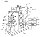
- Fig. 1 is a diagram illustrating an overall configuration of an analyzer 90.
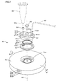
- Fig. 2 is a perspective assembly diagram of a cartridge 50.
- the analyzer 90 will be described as an apparatus for identifying the species of rice from DNA.
- the analyzer 90 includes a cartridge holding mechanism 80 to which the cartridge 50 can be attached, a reaction tank 30 in which liquid can be held, and a rotating mechanism 32 that rotates the cartridge 50 about a center axis of the cartridge 50.
- the analyzer 90 further includes a pump 34 that applies a differential pressure to a liquid container of the cartridge 50 and to the reaction tank 30 to transport liquid, a reaction-tank securing unit 36 that secures the reaction tank 30 to a supporting member 92, and a light detecting unit 60 that inputs light through an optical fiber 62 and detects the light.
- the analyzer 90 further includes a start button (not shown) the user uses to give an instruction to start processing in the analyzer 90, and a controller 40 that controls an overall operation of the analyzer 90.
- the analyzer 90 further includes a Peltier device 38a that can regulate the temperature of the cartridge 50 held by the cartridge holding mechanism 80, and a Peltier device 36a that can regulate the temperature of the reaction tank 30.
- the analyzer 90 has a rectangular base 90a at the bottom, and the supporting member 92 disposed on the front side of the base 90a.
- the supporting member 92 is L-shaped in side view.
- the supporting member 92 has a middle surface 92a and an upright wall portion 92b standing upward on the back side of the middle surface 92a.
- the pump 34 and the controller 40 are provided behind the supporting member 92.
- the cartridge 50 includes a circular valve 51 into which the reaction tank 30 is inserted, a ring array 53 in which a plurality of DNA probes 53a are spotted along a circumference of the ring array 53, and a cartridge body 54 to which the circular valve 51 and the ring array 53 are attached with a center pin 55.
- a plurality of ports are arranged side-by-side in an upper side of the cartridge body 54.
- the circular valve 51 is a circular member coaxial with a center axis 59 of the cartridge body 54.
- the circular valve 51 is provided with a condenser lens 57.
- the circular valve 51 is supported by the center pin 55 inserted through the center thereof.
- the circular valve 51 includes a block 51b at the top.
- the block 51b has upright walls 51c and 51c parallel to each other and a notch 51d.
- a retainer 84 sandwiches the upright walls 51c and 51c of the block 51b to unrotatably secure the circular valve 51.
- the circular valve 51 is connected to the reaction tank 30 through a tubular plastic packing 56, and has a through hole 51a vertically extending therethrough from a fluid port 30a at the lower end of the reaction tank 30.
- fluorine-based material such as Teflon (registered trademark) is used to form the circular valve 51.
- the material of the circular valve 51 and the mounting position of the condenser lens 57 are designed such that light incident from one of the plurality of DNA probes 53a is collimated by the condenser lens 57 and is incident on a collimating lens 62a attached to an end of the optical fiber 62. Note that the condenser lens 57 is bonded to the circular valve 51 by an adhesive after being separately produced.
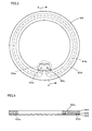
- Fig. 3 is a plan view of the ring array 53.
- Fig. 4 is a cross-sectional view of the ring array 53, the view being taken along line A-A' of Fig. 3 .
- the ring array 53 has a reaction channel 53b in which the DNA probes 53a are arranged in a row.
- the ring array 53 has a protrusion 53e protruding radially.
- a channel inlet 53c and a channel outlet 53d are formed on the upper side of the protrusion 53e.
- a lower member 363 and an upper member 364 are bonded together by an adhesive sheet 370 (e.g., 531N#80 produced by Nitto Denko Corporation, or titer stick produced by Kajixx Co., Ltd.) to form the ring array 53.
- the lower member 363 is a 0.1-mm-thick plate-like member made of polycarbonate.
- the upper member 364 is a 1.0-mm-thick plate-like member also made of polycarbonate.
- the adhesive sheet 370 has a through hole having a shape corresponding to the shape of the reaction channel 53b circumferentially formed.
- the reaction channel 53b is defined by bonding the upper member 364 and the lower member 363, with the adhesive sheet 370 interposed therebetween.
- the lower member 363 smaller in thickness than the upper member 364 is disposed on the lower side (adjacent to a rotating stage 38). Therefore, as compared to the case where the upper member 364 is disposed on the lower side, the temperature of liquid inside the reaction channel 53b can be regulated more easily by the Peltier device 38a (see Fig. 1 ) inside the rotating stage 38.
- the DNA probes 53a are spotted on the lower surface of the upper member 364, the lower surface being adjacent to the reaction channel 53b. As illustrated in Fig. 3 and Fig. 4 , the width and height of the reaction channel 53b are circumferentially constant.
- the cartridge body 54 is a disk-like member made of cyclo-olefin copolymer, and is composed of four disk-like layers: a first layer 54a, a second layer 54b, a third layer 54c, and a fourth layer 54d.
- Fig. 5 is a plan view of the first layer 54a of the cartridge body 54
- Fig. 6 is a plan view of the second layer 54b of the cartridge body 54
- Fig. 7 is a plan view of the third layer 54c of the cartridge body 54
- Fig. 8 is a plan view of the fourth layer 54d of the cartridge body 54.
- the cartridge body 54 has a recess at the center of the upper side thereof.
- the fourth layer 54d has, in its lower surface, three grooves 342 extending radially, and a filling opening 341 for filling a column.
- the cartridge body 54 has a plurality of liquid containers 302 to 304, 308, 309, 311, 315 to 321, 323, and 325 capable of holding liquids and a plurality of distribution ports 302a to 304a, 308a, 309a, 311a, 315a to 321a, 323a, and 325a.
- the cartridge body 54 When the cartridge body 54 is rotated, one of the distribution ports 302a to 304a, 308a, 309a, 311a, 315a to 321a, 323a, and 325a allows the corresponding liquid container to communicate with the reaction tank 30 at a predetermined position.
- the cartridge body 54 also has outside-air distribution portions 326 that allow the liquid containers 302 to 304, 308, 309, 311, 315 to 321, 323, and 325 to communicate with the outside air, so that the outside air can be taken in the liquid containers 302 to 304, 308, 309, 311, 315 to 321, 323, and 325, and gas can be exhausted from the liquid containers 302 to 304, 308, 309, 311, 315 to 321, 323, and 325.
- the cartridge body 54 also has waste liquid tanks 327 and 328 capable of holding waste liquids supplied from the reaction tank 30, a column containing space 306 containing a column capable of adsorbing a product of a reaction in the reaction tank 30, and a combined distribution port 306a. When the cartridge body 54 is rotated, the combined distribution port 306a allows one of the waste liquid tanks 327 and 328 to communicate with the reaction tank 30 at a predetermined position.
- the cartridge body 54 also has closed ports 301a, 305a, 307a, 312a, 322a, and 324a, each having no hole.
- the cartridge body 54 also has a closed channel 310 that does not communicate with the outside air and is capable of holding liquid, and an injection port 310a used to inject liquid into the closed channel 310 and supply liquid held in the closed channel 310 to the reaction tank 30.
- the ring array 53 is mounted on the cartridge body 54, the above-described ports of the cartridge body 54 and the channel inlet 53c of the ring array 53 are arranged along the circumference coaxial with the center axis 59.
- the liquid containers 302 to 304, 308, 309, 311, 315 to 321, 323, and 325 and the waste liquid tanks 327 and 328 may be collectively referred to as "chambers".
- the liquid containers 302 to 304, 308, 309, 311, 315 to 321, 323, and 325 each are a space narrowed at both ends.
- the liquid containers 304, 308, 309, 315, 316, 318, 319, 321, and 323 each are configured to hold a large amount of liquid and are formed as a space extending from the second layer 54b to the third layer 54c, while the liquid containers 302, 303, 311, 317, 320, and 325 each are configured to hold a small amount of liquid and are formed only in one of the second layer 54b and the third layer 54c.
- the liquid containers 302 to 304, 308, 309, 311, 315, 316, 318, 319, 321, 323, and 325 are connected, at their respective one ends adjacent to the center of the cartridge body 54, to the distribution ports 302a to 304a, 308a, 309a, 311a, 315a, 316a, 318a, 319a, 321a, 323a, and 325a, respectively, through channels formed in the lower surface of the third layer 54c and connected to the corresponding liquid containers, and further through vertical channels in the third layer 54c and the second layer 54b.
- the liquid containers 317 and 320 are connected, at their respective one ends adjacent to the center of the cartridge body 54, to the distribution ports 317a and 320a, respectively, through vertical channels formed in the third layer 54c and further through radial channels connected to the vertical channels.
- the liquid containers 302 to 304, 308, 309, 311, 315 to 321, 323, and 325 are connected, at their respective other ends remote from the center of the cartridge 50, to the outside-air distribution portions 326. A detailed description of the outside-air distribution portions 326 will be given later.
- the distribution ports 302a to 304a, 308a, 309a, 311a, 315a to 321a, 323a, and 325a are openings communicating with the liquid containers 302 to 304, 308, 309, 311, 315 to 321, 323, and 325, respectively.
- the distribution ports 302a to 304a, 308a, 309a, 311a, 315a to 321a, 323a, and 325a are used to supply liquids from the corresponding liquid containers 302 to 304, 308, 309, 311, 315 to 321, 323, and 325, and formed in the upper surface of the third layer 54c.
- the distribution ports 302a to 304a, 308a, 309a, 311a, 315a to 321a, 323a, and 325a are arranged along a circumference coaxial with a rotation axis about which the cartridge body 54 is rotated by the rotating mechanism 32. That is, the distribution ports 302a to 304a, 308a, 309a, 311a, 315a to 321a, 323a, and 325a are arranged along a circumference coaxial with the center axis 59 of the cartridge body 54.
- the liquid held in the liquid container can be supplied to the reaction tank 30.
- the outside-air distribution portion 326 is a general term used to refer to any of outside-air distribution channels 302c, 303c, 309c, 311c, and 325c formed in the lower surface of the third layer 54c and radially extending outward from the respective one ends of the liquid containers 302, 303, 309, 311, and 325 remote from the center of the cartridge body 54; outside-air distribution channels 317c and 320c formed in the lower surface of the second layer 54b and radially extending outward from the respective one ends of the liquid containers 317 and 320 remote from the center of the cartridge body 54; and air vents 302d to 304d, 308d, 309d, 311d, 315d to 321d, 323d, and 325d vertically formed in the first layer 54a.
- the air vents 302d, 303d, 309d, 311d, and 325d allow the corresponding liquid containers 302, 303, 309, 311, and 325 to communicate with the outside air, through the corresponding outside-air distribution channels 302c, 303c, 309c, 311c, and 325c and further through the corresponding channels vertically formed in the second layer 54b and the third layer 54c.
- the air vents 317d and 320d allow the corresponding liquid containers 317 and 320 to communicate with the outside air, through the corresponding outside-air distribution channels 317c and 320c and further through the corresponding channels vertically formed in the second layer 54b.
- the air vents 304d, 308d, 315d, 316d, 318d, 319d, 321d, and 323d allow the corresponding liquid containers 304, 308, 315, 316, 318, 319, 321, and 323 to directly communicate with the outside air.
- the waste liquid tanks 327 and 328 each are a space provided along the outermost circumference of the cartridge body 54 and formed as a single space extending from the second layer 54b to the third layer 54c.
- the waste liquid tank 327 is connected to the column containing space 306 through a radially extending waste liquid channel 327e connected to the waste liquid tank 327 and formed in the second layer 54b, a channel vertically extending through the second layer 54b from one end of the waste liquid channel 327e adjacent to the center of the cartridge body 54, and a diffusion channel 327f connected to this channel and extending radially.
- waste liquid tank 328 is connected, through a waste liquid channel 328e connected to the waste liquid tank 328, to a vertical channel 328f provided in the second layer 54b.
- the channel 328f is connected to a vertical channel 328g provided in the third layer 54c.
- the channel 328g is connected to a connection port 328h, through a radial channel and a vertical channel that are provided in the third layer 54c. That is, when the ring array 53 is mounted on the cartridge body 54, the channel outlet 53d (see Fig. 3 ) of the ring array 53 is connected to the connection port 328h.
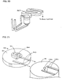
- Fig. 24 three-dimensionally illustrates the channel from the connection port 328h to the waste liquid tank 328.
- the first layer 54a has air vents 327d and 328d that allow their corresponding waste liquid tanks 327 and 328 to communicate with the outside air.
- the column containing space 306 is provided between the combined distribution port 306a and the diffusion channel 327f, and includes a column.
- a ceramic column e.g., silica gel column
- the pump 34 is actuated to increase pressure in the reaction tank 30, liquid held in the reaction tank 30 is distributed to the column containing space 306 and allowed to collect in the diffusion channel 327f. If further pressure is applied, the liquid collecting in the diffusion channel 327f is stored in the waste liquid tank 327. If the applied pressure is reduced, the liquid passes through the column containing space 306 again and is stored in the reaction tank 30.
- Filling the column of the column containing space 306 is effected by covering the lower surface of the fourth layer 54d after filling the column from the lower surface of the fourth layer 54d through the filling opening 341.
- replacement of the column in the column containing space 306 is effected by uncovering the lower surface of the fourth layer 54d, if necessary.
- the combined distribution port 306a and the channel inlet 53c of the ring array 53 are openings that communicate with the waste liquid tanks 327 and 328, respectively, and through which liquids are eventually stored in the waste liquid tanks 327 and 328.
- the combined distribution port 306a is provided in the upper surface of the third layer 54c, and the channel inlet 53c is provided in the upper surface of the ring array 53 (see Fig. 3 ).
- the combined distribution port 306a and the channel inlet 53c are arranged side-by-side along the circumference coaxial with the rotation axis about which the cartridge body 54 is rotated by the rotating mechanism 32 (see Fig. 1 ). That is, the combined distribution port 306a and the channel inlet 53c are arranged side-by-side along the circumference coaxial with the center axis 59 of the cartridge body 54.
- the closed ports 301a, 305a, 307a, 312a, 322a, and 324a are non-hole portions of the third layer 54c, and their positions are defined by the linked packing member 52 (see Fig. 2 ).
- the linked packing member 52 is an integrally-molded member having a plurality of O-rings arranged in a row along the circumference.
- the closed channel 310 is formed as a groove in the third layer 54c.
- the closed channel 310 is connected to the injection port 310a through a radially extending channel formed in the third layer 54c and a vertical channel connected to this radially extending channel.
- one end of the closed channel 310 remote from the center of the cartridge body 54 is not connected to any of the outside-air distribution portions 326. Therefore, when the closed channel 310 does not communicate with the reaction tank 30, the injection port 310a is closed by the lower surface of the circular valve 51, so that the closed channel 310 becomes a closed space.
- the injection port 310a is an opening communicating with the closed channel 310 and provided in the upper surface of the third layer 54c.
- the injection port 310a is used to store liquid in the closed channel 310 or supply liquid held in the closed channel 310 to the reaction tank 30.
- the injection port 310a and the other ports are arranged along the circumference coaxial with the rotation axis about which the cartridge body 54 is rotated by the rotating mechanism 32 (see Fig. 1 ). That is, injection port 310a and the other ports are arranged along the circumference coaxial with the center axis 59 of the cartridge body 54.
- the cartridge holding mechanism 80 is a mechanism to which the cartridge 50 is attached.
- Fig. 9 is an explanatory diagram illustrating the cartridge holding mechanism 80.
- the cartridge holding mechanism 80 includes the retainer 84 that biases the cartridge 50 downward, and the rotating stage 38 on which the cartridge 50 is placed.
- fluorine-based material such as Teflon, is used to form the retainer 84.
- the retainer 84 presses the circular valve 51 downward while sandwiching the upright walls 51c and 51c of the block 51b.
- the retainer 84 has a contact portion 84a, as illustrated in Fig. 9 .
- the contact portion 84a is fitted into contact with the notch 51d of the circular valve 51.
- the rotating mechanism 32 includes the rotating stage 38 on which the cartridge 50 is placed, and a motor 37 that rotates the rotating stage 38 in a stepwise manner such that the rotating stage 38 is secured at a predetermined position.
- the rotating stage 38 is a disk-like member rotatably supported by a shaft on the middle surface 92a of the supporting member 92.
- the rotating stage 38 is formed by applying electroless nickel plating to a copper member.
- the rotating stage 38 has three raised portions 38b (see Fig. 9 ) formed on its upper surface.
- the bottom surface of the cartridge body 54 has the three grooves 342 (see Fig. 8 ) at positions corresponding to the raised portions 38b.
- the cartridge 50 and the rotating stage 38 are combined by fitting the raised portions 38b into the corresponding grooves 342.
- the Peltier device 38a for the cartridge 50 is provided inside the rotating stage 38. By regulating the temperature of the rotating stage 38, the Peltier device 38a can regulate the temperature of the cartridge 50 on the rotating stage 38 at a constant level.
- the material used to form the rotating stage 38 may be an anodized aluminum.
- the motor 37 mentioned above is a stepping motor.
- the reaction-tank securing unit 36 is formed by applying electroless nickel plating to a copper member.
- the reaction-tank securing unit 36 is secured to the center of the upright wall portion 92b of the supporting member 92.
- the reaction-tank securing unit 36 removably secures the reaction tank 30.
- the Peltier device 36a for the reaction tank 30 is provided inside the reaction-tank securing unit 36. By regulating the temperature of the reaction-tank securing unit 36, the Peltier device 36a can regulate the temperature of the reaction tank 30 at a constant level.
- the material used to form the reaction-tank securing unit 36 may be an anodized aluminum.
- the reaction tank 30 is made of polypropylene. As illustrated in Fig. 1 and Fig. 2 , the reaction tank 30 is a tubular member tapered downward toward the corresponding port. The reaction tank 30 is attached at its lower end through the packing 56 to the circular valve 51 (see Fig. 2 ), and connected at its upper end to an air supply/exhaust tube 34a (see Fig. 1 ). Pressure generated by actuation of the pump 34 is applied through the air supply/exhaust tube 34a to the reaction tank 30. The pressure is further applied to any of the chambers of the cartridge body 54 connected to the reaction tank 30 through the circular valve 51. In the reaction tank 30, liquids absorbed from the liquid containers 302 to 304, 308, 309, 311, 315 to 321, 323, and 325 are held, stirred, and subjected to various reactions.
- the pump 34 is a so-called tube pump that applies pressure, by squeezing its tube with rollers, to a component connected to the tube. As illustrated in Fig. 1 , the pump 34 is connected to the air supply/exhaust tube 34a. The pump 34 applies pressure, through the air supply/exhaust tube 34a and the reaction tank 30, to liquid held in the corresponding chamber of the cartridge 50. By appropriately setting the direction and speed of rotation of a stepping motor connected to the pump 34, it is possible to increase or decrease the pressure applied by the pump 34 to a component connected to the air supply/exhaust tube 34a.
- switching between an operation of supplying liquid from the reaction tank 30 to the cartridge 50 and an operation of supplying liquid from the cartridge 50 to the reaction tank 30 is made by actuating the pump 34 after the direction and speed of the stepping motor connected to the pump 34 are set.
- the direction and speed of rotation of the stepping motor are set such that the pressure indicated by a pressure gage (not shown) in the air supply/exhaust tube 34a reaches a desired value.
- the light detecting unit 60 includes the optical fiber 62 that transmits light incident from each of the DNA probes 53a, and a light detecting module 64 that converts light input through the optical fiber 62 into an electric signal.
- the optical fiber 62 is secured by the retainer 84 (see Fig. 9 ) of the cartridge holding mechanism 80.
- the optical fiber 62 has the collimating lens 62a attached to its one end.
- the collimating lens 62a serves as a light detector indicating a position at which light is detected.
- the optical fiber 62 is secured to the retainer 84 such that when the cartridge 50 is attached to the cartridge holding mechanism 80, the collimating lens 62a and the condenser lens 57 are opposite each other in the vertical direction.
- the light detecting module 64 is internally provided with a light detecting element (not shown) that detects light input through the optical fiber 62.
- the light detecting element outputs an electric signal corresponding to the intensity of received light.
- the controller 40 is configured as a microprocessor centered on a CPU 42.
- the controller 40 includes a flash ROM 43 that stores various processing programs, and a RAM 44 that temporarily stores or saves data.
- the controller 40 outputs a control signal to the pump 34, a control signal to the motor 37, a control signal to the light detecting unit 60, and supply voltages to the Peltier device 36a for the reaction tank and the Peltier device 38a for the cartridge.
- the controller 40 inputs a detection signal from the light detecting unit 60.
- FIG. 10 illustrates part of a cross section taken along line B-B' of Fig. 2 .
- Fig. 10 illustrates a state in which the cartridge body 54 is rotated relative to the circular valve 51 and positioned such that the through hole 51a of the circular valve 51 coincides with the channel inlet 53c of the ring array 53.
- the collimating lens 62a and the DNA probe 53a are opposite each other.
- the reaction tank 30 communicates with the channel inlet 53c through the through hole 51a of the circular valve 51.
- the cartridge 50 in which the ring array 53 is mounted on the cartridge body 54 in advance is used.
- desired amounts of liquids including reagents used in predetermined reactions are separately stored in appropriate liquid containers.
- the motor 37 rotates the cartridge body 54 to allow the different ports of the cartridge body 54 to be sequentially connected to the reaction tank 30.
- purification of a reaction product is effected by adsorbing the reaction product to a column and discharging waste liquid to the waste liquid tank 327, eluting the reaction product adsorbed to the column with liquid held in any of the liquid containers, allowing the eluted reaction product to temporarily collect in the diffusion channel 327f, and supplying the eluted reaction product to the reaction tank 30.
- the reaction tank 30 of the analyzer 90 is provided outside the cartridge 50, changes in temperature in the reaction tank 30 are not easily transmitted to the cartridge 50. Therefore, temperatures in the reaction tank 30 and the cartridge 50 can be kept at different levels (e.g., a reaction temperature and a storage temperature).
- a motor (not shown) that rotates a magnet attached thereto is provided beside the reaction-tank securing unit 36, and a rotor including a magnet is provided inside the reaction tank 30.
- the motor rotates the magnet attached thereto, the rotor rotates to stir liquid in the reaction tank 30.
- Fig. 11 is an explanatory diagram illustrating a process of amplifying and preparing genomic DNA of rice.
- Fig. 12 is an explanatory diagram illustrating a process of causing the prepared genomic DNA to react with the DNA probes 53a formed in the ring array 53.
- FIG. 12 schematically illustrate the liquid containers and the waste liquid tanks 327 and 328 of the cartridge 50, the injection port and distribution ports connected the chambers, and the reaction tank 30.
- the liquid containers 302 to 304, 308, 309, 311, 315 to 321, 323, and 325 and the waste liquid tanks 327 and 328 are illustrated with descriptions of the types and amounts of liquids held and the reference numerals shown in Fig. 5 to Fig. 8 .
- chambers represented by blank spaces hold no liquid therein.
- the reaction tank 30 holding liquid therein is represented by a rounded rectangle
- the reaction tank 30 holding liquid to be processed is represented by a rectangle
- the reaction tank 30 holding no liquid therein is represented by an empty rounded rectangle.
- Each arrow in the drawings indicates a direction in which liquid or gas flows. For convenience of explanation, step numbers are given to the representations of the reaction tank 30.
- the user first prepares the cartridge 50 in which liquids for identification of species of rice are stored. Next, the user places, in the reaction tank 30, genomic DNA of rice whose species is to be identified. The user then connects the reaction tank 30 to the circular valve 51 of the cartridge 50. Next, the user opens a door (not shown) on one side of the reaction-tank securing unit 36, connects the upper part of the reaction tank 30 to the air supply/exhaust tube 34a, and horizontally slides the cartridge 50 onto the rotating stage 38 such that the circular valve 51 is biased downward by the retainer 84.
- the retainer 84 which is made of Teflon, bends to allow the cartridge 50 to be placed on the rotating stage 38 such that the three raised portions 38b on the upper surface of the rotating stage 38 are fitted into the corresponding three grooves 342 (see Fig. 8 ) formed at the bottom of the cartridge body 54.
- the cartridge 50 is mounted on the rotating stage 38 while being biased downward by the retainer 84.
- the contact portion 84a of the retainer 84 is fitted into contact with the notch 51d of the circular valve 51 of the cartridge 50, so that the collimating lens 62a and the condenser lens 57 are secured at positions where they face each other in the vertical direction.
- the CPU 42 of the controller 40 reads and executes a DNA preparation routine stored in the flash ROM 43.
- the CPU 42 drives the motor 37 to rotate the cartridge body 54 so as to allow the distribution port 302a to communicate with the reaction tank 30, actuates the pump 34 to reduce air pressure in the reaction tank 30, and allows liquid held in the liquid container 302 to be drawn into the reaction tank 30 (step S1100).
- the CPU 42 allows the distribution port 303a to communicate with the reaction tank 30, and actuates the pump 34 to allow liquid held in the liquid container 303 to be drawn out (step S1110).
- the CPU 42 rotates the cartridge body 54 to allow the closed port 305a to be connected to the reaction tank 30, and performs stirring for 15 minutes to allow a reaction to occur in the reaction tank 30 while keeping the temperature therein at 95°C.
- the CPU 42 performs 40 cycles, each involving stirring for 1 minute in the reaction tank 30 kept at a temperature of 95°C, stirring for 1 minute and 30 seconds at a temperature of 66°C, and stirring for 30 seconds at a temperature of 72°C.
- the CPU 42 performs stirring for 10 minutes at a temperature of 72°C to allow a reaction to occur (step S1120).
- the term “stirring” means to mix solutions in the reaction tank 30 by causing the motor 72 to rotate the rotor 47 placed in the reaction tank 30.
- the CPU 42 allows the distribution port 304a to communicate with the reaction tank 30, and actuates the pump 34 to allow liquid (adsorption buffer (3.8 mol/L, ammonium sulfate)) held in the liquid container 304 to be drawn out (step S1130).
- the CPU 42 allows the combined distribution port 306a to communicate with the reaction tank 30, and actuates the pump 34 to distribute the mixed solution in the reaction tank 30 to the column containing space 306 (step S1140).
- the CPU 42 allows the distribution port 323a to communicate with the reaction tank 30, actuates the pump 34 to allow liquid (first wash buffer (1.9 mol/L, ammonium sulfate)) held in the liquid container 323 to be drawn out, performs stirring for 1 minute while keeping the temperature in the reaction tank 30 at 25°C, and washes the inside of the reaction tank 30 (step S1150). The inside of the reaction tank 30 is washed to prevent salt precipitation.
- the CPU 42 actuates the pump 34 to store, in the liquid container 323, the liquid used for washing the reaction tank 30 (step S1160).
- the CPU 42 allows the combined distribution port 306a to communicate with the reaction tank 30, actuates the pump 34 to distribute the second wash buffer in the reaction tank 30 to the column containing space 306, and thereby washes the column (step S1180).
- the CPU 42 allows the distribution port 309a to communicate with the reaction tank 30, actuates the pump 34 to allow liquid (elution buffer (pH 8.0, 20 mmol/L, tris-hydrogen chloride) held in the liquid container 309 to be drawn out (step S1190).
- the CPU 42 allows the combined distribution port 306a to communicate with the reaction tank 30, actuates the pump 34 to distribute the elution buffer in the reaction tank 30 to the column containing space 306, and allows the eluate to collect in the diffusion channel 327f, not to flow out to the waste liquid tank 327 (step S1200).
- the CPU 42 causes the pump 34 (tube pump) to stop squeezing the tube. Since this allows amplified DNA adsorbed to the column to be eluted into the elution buffer, the solution containing the amplified DNA collects in the diffusion channel 327f.
- step S1200 the CPU 42 actuates the pump 34 to allow the elution buffer collecting in the diffusion channel 327f to be drawn back to the reaction tank 30 (step S1210).
- the CPU 42 allows the injection port 310a to communicate with the reaction tank 30, and actuates the pump 34 to inject the elution buffer in the reaction tank 30 into the closed channel 310 (step S1220).
- air in the closed channel 310 is compressed by the injected liquid and increased in pressure.
- the CPU 42 allows the distribution port 309a to communicate with the reaction tank 30, so as to allow the mixed solution remaining in the reaction tank 30 to be discharged to the liquid container 309 (step S1230).
- the pressure used in step S1220 to inject the mixed solution into the closed channel 310 remains in the reaction tank 30.
- step S1240 the mixed solution is discharged to the liquid container 309 by the pressure remaining in the reaction tank 30, the pressure in the reaction tank 30 is reduced.
- the pressure of air in the closed channel 310 remains the same as that used for injection of the mixed solution in step S1220. Therefore, this difference in pressure causes the mixed solution injected into the closed channel 310 to be supplied to the reaction tank 30.
- the CPU 42 of the controller 40 reads and executes a reaction processing routine stored in the flash ROM 43. This routine is executed following the completion of execution of the DNA preparation routine described above.
- the CPU 42 allows the distribution port 311a to communicate with the reaction tank 30 holding the prepared DNA, and actuates the pump 34 to allow liquid held in the liquid container 311 to be drawn out (step S1300).
- the CPU 42 rotates the cartridge body 54 to allow the closed port 312a to be connected to the reaction tank 30, and performs stirring for 5 minutes while keeping the temperature in the reaction tank 30 at 90°C (step S1310).
- the CPU 42 performs stirring for 5 minutes while keeping the temperature in the reaction tank 30 at 10°C (step S1320).
- the CPU 42 allows the channel inlet 53c to communicate with the reaction tank 30, and controls the actuation of the pump 34 to allow the mixed solution held in the reaction tank 30 to temporarily collect in the reaction channel 53b of the ring array 53.
- the CPU 42 While causing the Peltier device 38a for the cartridge 50 to keep the temperature in the reaction channel 53b at 42°C for 60 minutes, the CPU 42 allows a hybridization reaction to occur between the DNA probe 53a formed in the reaction channel 53b and target DNA in the mixed solution. Then, the CPU 42 actuates the pump 34 again to increase air pressure in the reaction tank 30, and allows the liquid temporarily collecting in the reaction channel 53b to be discharged to the waste liquid tank 328 (step S1330). Here, the mixed solution distributed to the ring array 53 is transported to the waste liquid tank 328 along the path described above.
- the CPU 42 allows the distribution port 315a to communicate with the reaction tank 30, and actuates the pump 34 to allow liquid held in the liquid container 315 to be drawn out (step S1340).
- the CPU 42 allows the channel inlet 53c to communicate with the reaction tank 30, controls the actuation of the pump 34 to allow wash liquid held in the reaction tank 30 to temporarily collect in the reaction channel 53b of the ring array 53, and thus washes the reaction channel 53b while causing the Peltier device 38a to keep the temperature in the reaction channel 53b at 25°C for 5 minutes.
- the CPU 42 actuates the pump 34 again to increase air pressure in the reaction tank 30, and allows the wash liquid temporarily collecting in the reaction channel 53b to be discharged to the waste liquid tank 328 (step S1350).
- the CPU 42 performs processing similar to that of step S1340 and step S1350 using liquid held in the liquid container 316 so as to wash the reaction channel 53b of the ring array 53 (step S1360 and step S1370).
- the CPU 42 allows the distribution port 317a to communicate with the reaction tank 30, and actuates the pump 34 to allow liquid held in the liquid container 317 to be drawn out (step S1380).
- the CPU 42 allows the channel inlet 53c to communicate with the reaction tank 30, controls the actuation of the pump 34 to allow liquid held in the reaction tank 30 to temporarily collect in the reaction channel 53b of the ring array 53, and causes a chemiluminescent reaction of the DNA probe 53a to occur while keeping the temperature in the reaction channel 53b at 25°C for 30 minutes.
- the CPU 42 actuates the pump 34 again to increase air pressure in the reaction tank 30, and allows the liquid temporarily collecting in the reaction channel 53b to be discharged to the waste liquid tank 328 (step S1390).
- the CPU 42 performs processing similar to that of step S1340 and step S1350 using liquids held in the liquid containers 318 and 319 so as to wash the reaction channel 53b of the ring array 53 (step S1400 to step S1430).
- the CPU 42 allows the distribution port 320a to communicate with the reaction tank 30, and actuates the pump 34 to allow liquid held in the liquid container 320 to be drawn out (step S1440).
- the CPU 42 allows the channel inlet 53c to communicate with the reaction tank 30, controls the actuation of the pump 34 to allow liquid held in the reaction tank 30 to temporarily collect in the reaction channel 53b of the ring array 53, and causes a pigmentation reaction of the DNA probe 53a to occur while keeping the temperature in the reaction channel 53b at 25°C for 30 minutes. Then, the CPU 42 actuates the pump 34 again to increase air pressure in the reaction tank 30, and allows the liquid temporarily collecting in the reaction channel 53b to be discharged to the waste liquid tank 328 (step S1450). Next, the CPU 42 allows the distribution port 321a to communicate with the reaction tank 30, and actuates the pump 34 to allow liquid held in the liquid container 321 to be drawn out (step S1460).
- the CPU 42 allows the channel inlet 53c to communicate with the reaction tank 30, and distributes liquid held in the reaction tank 30 to the reaction channel 53b of the ring array 53 so as to stop the pigmentation reaction of the DNA probe 53a (step S1470).
- the pigmented DNA can be obtained in the ring array 53 (step S1480).
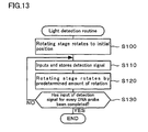
- Fig. 13 is a flowchart illustrating an example of the light detection routine. This routine is executed following the completion of execution of the reaction processing routine described above.
- the CPU 42 controls the motor 37 such that the rotating stage 38 rotates to an initial position (step S100).
- the initial position is a position at which, of the plurality of DNA probes 53a, the first DNA probe 53a determined in advance faces the condenser lens 57 in the vertical direction.
- the CPU 42 inputs a detection signal from the light detecting unit 60 and stores the received detection signal in the RAM 44 (step S110).
- step S120 the CPU 42 controls the motor 37 such that the rotating stage 38 rotates by a predetermined amount of rotation.
- the predetermined amount of rotation is an amount by which the rotating stage 38 rotates from a position which allows one DNA probe 53a to face the condenser lens 57, to another position which allows another DNA probe 53a spotted adjacent to the one DNA probe 53a to face the condenser lens 57.
- the CPU 42 determines whether the input of a detection signal for every DNA probe 53a has been completed (step S130).
- This determination is made, for example, on the basis of whether the total amount by which the rotating stage 38 has rotated since the light detection routine was started has reached an angle by which the DNA probes 53a have been spotted, whether the rotating stage 38 has rotated once, or whether the number of detection signals stored in the RAM 44 has reached the number of DNA probes 53a spotted in advance. In this example, the determination is made on the basis of whether the total amount by which the rotating stage 38 has rotated from the initial position has reached an angle by which the DNA probes 53a have been spotted. If a negative determination is made in step S130, that is, if a detection signal for at least one of the DNA probes 53a has not been input, the processing of step S110 and the subsequent steps is performed.
- step S130 If a positive determination is made in step S130, that is, if the input of a detection signal for every DNA probe 53a has been completed, the present routine ends.
- a plurality of detection signals stored in the RAM 44 represent a pigmentation pattern.
- pigmentation patterns of different species of rice are obtained and stored in the flash ROM 43.
- a pigmentation pattern In an array used for such visual identification of a pigmentation pattern, if DNA probes are spotted along a circumference, it is possible to identify a pigmentation pattern from its direction, in such a manner as to read the time (e.g., three o'clock, four o'clock, or five o'clock) from the direction of hands of an analog clock.
- the ring array 53 may be marked at zero o'clock, three o'clock, six o'clock, and nine o'clock positions.
- the cartridge 50 of the present embodiment corresponds to a DNA-array-equipped cartridge of the present invention.
- the cartridge body 54 and the ring array 53 of the present embodiment correspond to a housing of the present invention.
- the liquid containers 302 to 304, 308, 309, 311, 315 to 321, 323, and 325 and the reaction channel 53b of the present embodiment correspond to fluid containing spaces of the present invention.
- the liquid containers 302 to 304, 308, 309, 311, 315 to 321, 323, and 325 of the present embodiment correspond to reagent containing spaces of the present invention.
- the reaction channel 53b of the present embodiment corresponds to a DNA array space of the present invention.
- the distribution ports 302a to 304a, 308a, 309a, 311a, 315a to 321a, 323a, and 325a and the channel inlet 53c of the present embodiment correspond to openings of the present invention.
- the circular valve 51 of the present embodiment corresponds to a circular valve of the present invention.
- the condenser lens 57 of the present embodiment corresponds to a light guide of the present invention.
- the cartridge holding mechanism 80 of the present embodiment corresponds to a holder of the present embodiment.
- the rotating stage 38 and the motor 37 of the present embodiment correspond to a rotator of the present invention.
- the collimating lens 62a of the present embodiment corresponds to a light detector of the present invention.
- the pump 34 of the present embodiment corresponds to a liquid transporter of the present invention.
- the cartridge body 54 when the cartridge body 54 is rotated such that the distribution ports 302a to 304a, 308a, 309a, 311a, 315a to 321a, 323a, and 325a of the liquid containers 302 to 304, 308, 309, 311, 315 to 321, 323, and 325 sequentially face the fluid port 30a of the reaction tank 30, the rotation of the cartridge body 54 is temporarily stopped in a state in which the reaction tank 30 faces each of the distribution ports 302a to 304a, 308a, 309a, 311a, 315a to 321a, 323a, and 325a, so that fluid is transported between the reaction tank 30 and each of the liquid containers 302 to 304, 308, 309, 311, 315 to 321, 323, and 325.
- target DNA can be prepared and eventually stored in the reaction tank 30.
- the cartridge body 54 is rotated such that the channel inlet 53c faces the fluid port 30a of the reaction tank 30, it is possible to allow the target DNA in the reaction tank 30 to flow into the reaction channel 53b, and thus to allow the target DNA to react with each of the DNA probes 53a.
- the cartridge body 54 is rotated, light incident from each of the DNA probes 53a subjected to the reaction can be detected by the collimating lens 62a of the light detecting unit 60.
- the collimating lens 62a of the light detecting unit 60 it is possible to relatively easily carry out the process from preparation of the target DNA to detection of light incident from each of the DNA probes 53a at the collimating lens 62a.
- the cartridge body 54 is easily rotatable since it has a disk-like shape.
- the cartridge body 54 is provided with the circular valve 51, and rotating the cartridge body 54 allows the distribution ports 302a to 304a, 308a, 309a, 311a, 315a to 321a, 323a, and 325a, the combined distribution port 306a, and the channel inlet 53c to sequentially face the through hole 51a of the circular valve 51.
- any one of the chambers and the reaction channel 53b can communicate with the reaction tank 30.
- the circular valve 51 has the condenser lens 57, the structure becomes simpler than the case where they are formed separately.
- the circular valve 51 has the condenser lens 57, light incident from each of the DNA probes 53a can be efficiently guided to the collimating lens 62a serving as a light detector.
- the channel outlet 53d of the ring array 53 extends downward from the connection port 328h, bends radially outward, extends upward, and then is connected to the waste liquid tank 328 through the horizontal waste liquid channel 328e.
- the mixed solution in the reaction channel 53b can be prevented from gradually flowing into the waste liquid tank 328. That is, since the design is considered such that the liquid level of the mixed solution stops at a position in the middle of the vertical channels 328g and 328f, the mixed solution does not flow into the waste liquid channel 328e beyond the liquid surface.
- the mixed solution in the reaction channel 53b can be prevented from flowing into the waste liquid tank 328 as time passes.
- the plurality of DNA probes 53a are arranged in a row along a circumference.
- the plurality of DNA probes 53a may be arranged in two or more rows along circumferences having different radii. This makes it possible to spot a larger number of DNA probes 53a.
- the DNA probes 53a may be spotted in two rows along circumferences that are coaxial with the center axis 59 and have different diameters.
- two light detecting units 60 each corresponding to the DNA probes 53a in each row, may be provided.
- the condenser lens 57 and the optical fiber 62 are provided at positions opposite relative to one of the DNA probes 53a in each row.
- the plurality of DNA probes 53a are arranged in a row along a circumference.
- a plurality of DNA probes may be spotted for each of the various DNA probes 53a arranged in a row.
- two points each may be spotted, as illustrated in Fig. 14 .
- the area where the light detecting unit 60 detects light may be an area that entirely covers the two spotted points.
- the intensity of detected light can be made greater than that in the case where only one point is spotted for each of the various DNA probes 53a.
- three points may be spotted in an overlapping manner for each of the various DNA probes 53a.
- each DNA probe is formed in a dot (circular spot) shape in the reaction channel 53b by spraying microdroplets of solution containing DNA probes.
- each DNA probe may have a shape other than a circular shape.
- each DNA probe may have an elliptical shape or a rectangular shape, or may be formed as a string of circular spots.
- the cartridge body 54 and the ring array 53 are provided as separate units in the embodiment described above, but they may be provided as a single unit.
- the analyzer 90 includes the light detecting module 64 in the embodiment described above.
- the light detecting module 64 may be replaced with an external light detecting module, to which the optical fiber 62 is connected.
- the controller 40 transmits and receives control signals and detection signals to and from the external light detecting module.
- the analyzer 90 is configured such that, after a pigmentation reaction, light incident from each of the DNA probes 53a is detected through the optical fiber 62 by the light detecting module 64.
- the analyzer 90 may perform the following process. First, for preparing target DNA, the analyzer 90 fluorescently labels the target DNA and allows the prepared target DNA to be distributed to the reaction channel 53b. Thus, the fluorescently-labeled target DNA is located at a position of one of the plurality of DNA probes 53a, the one having been subjected to hybridization reaction with the target DNA. Next, light for producing fluorescence is applied to the DNA probes 53a.
- Fluorescence is produced at the position of the DNA probe 53a having been subjected to hybridization reaction with the target DNA, and is detected by the light detecting unit 60. This allows the user to recognize which of the DNA probes 53a has reacted with the target DNA, and thus to identify the target DNA.
- the analyzer 90 includes a light emitting unit that applies light for producing fluorescence to the DNA probes 53a.
- the light detecting module 64 may include the light emitting unit that applies, through the optical fiber 62, light for producing fluorescence to the DNA probes 53a.
- a filter may be provided between the light emitting unit and an end of the optical fiber 62 inside the light detecting module 64.
- the filter allows light for producing fluorescence, the light being to be incident on the optical fiber 62, to pass through such that the light output from the optical fiber 62 is divided into fluorescence and light for producing fluorescence.
- the light detecting element is provided at a position at which the resulting fluorescence is received.
- a cartridge 150 including a highly thermal-conductive member 58 may be used.
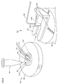
- Fig. 16 is a perspective assembly diagram of the cartridge 150.
- the cartridge 150 includes the highly thermal-conductive member 58 disposed opposite the collimating lens 62a with respect to the ring array 53. That is, the highly thermal-conductive member is disposed under the ring array 53.
- the highly thermal-conductive member 58 is an annular member made of carbon-containing resin or metal.
- the highly thermal-conductive member 58 having relatively high thermal conductivity is disposed under the ring array 53. Therefore, for a hybridization reaction between target DNA and the DNA probe 53a, it is possible to reduce variations in temperature among the spotted DNA probes 53a.
- a low-reflection ring 158 may be disposed on the same side as the collimating lens 62a of the optical fiber 62 with respect to the ring array 53, that is, the low-reflection ring 158 may be disposed above the ring array 53.
- the low-reflection ring 158 is made of a material similar to that of the highly thermal-conductive member 58.
- the low-reflection ring 158 has a through portion 158a at a position at which the through portion 158a faces the collimating lens 62a. Fluorescence from the DNA probes 53a of the ring array 53 can pass through the through portion 158a and be incident on the collimating lens 62a through the condenser lens 57. Thus, fluorescence other than the intended fluorescence can be further reliably prevented from being produced by the applied light.
- the circular valve 51 has the condenser lens 57 in the embodiment described above, the circular valve 51 may be one without the condenser lens 57.
- the cartridge body 54 is composed of four layers, that is, the first layer 54a, the second layer 54b, the third layer 54c, and the fourth layer 54d.
- the cartridge body 54 does not necessarily need to be composed of four layers.
- the cartridge body 54 may be composed of three layers or five layers.
- the cartridge body 54 of the above embodiment has a disk-like shape
- the cartridge body 54 may have another shape, such as a rectangular shape or a hexagonal shape.
- the DNA preparation routine, the reaction processing routine, and the light detection routine are executed by the controller 40.
- an operation corresponding to these routines may be manually performed by the operator.
- the ring array 53 is used to identify a species of rice.
- the ring array 53 may be used for a different reaction.
- DNA probes for this different reaction may be formed in the reaction channel 53b.
- the cartridge body 54 may hold liquids for use in this different reaction.
- the bottom of the column containing space 306 may be connected to a channel 306b extending downward from the combined distribution port 306a and then extending radially outward.
- the upper surface of the column containing space 306 may be connected to the diffusion channel 327f connected to the waste liquid tank 327.
- step S1150 the inside of the reaction tank 30 is washed with the first wash buffer held in the liquid container 323.
- step S1160 the liquid used for washing the reaction tank 30 is stored in the liquid container 323.
- steps S1170 and S1180 the second wash buffer held in the liquid container 308 flows from the combined distribution port 306a, passes through the channel 306b, passes through the column in the column containing space 306 from the lower side to the upper side in the reaction tank 30, passes through the diffusion channel 327f, and then flows into the waste liquid tank 327.
- the column is washed.
- the elution buffer held in the liquid container 309 flows from the combined distribution port 306a, passes through the channel 306b, passes through the column in the column containing space 306 from the lower side to the upper side in the reaction tank 30, and stops in the middle of the diffusion channel 327f (so as not to flow into the waste liquid tank 327).
- the DNA absorbed to the column is separated from the column and eluted into the elution buffer.
- the elution buffer (containing the DNA) in the diffusion channel 327f is drawn back to the reaction tank 30 through the combined distribution port 306a and the elution buffer is recovered.
- a combined distribution port 306c may be disposed next to the combined distribution port 306a and arranged in parallel to the combined distribution port 306a.
- a channel 306d may extend downward from the combined distribution port 306c, extend radially outward, and then extend upward.
- the upper surface of the column containing space 306 may be connected to the channel 306d.
- the combined distribution port 306a is referred to as a first combined distribution port 306a
- the combined distribution port 306c is referred to as a second combined distribution port 306c.
- steps S1140 to S1160 will be omitted because these steps are similar to those in Fig. 18 .
- the diffusion channel 327f is washed. This point differs from the steps in Fig. 18 .
- the wash liquid for example, distilled water
- the wash liquid in the channel is supplied from the second combined distribution port 306c with pressure. Then, the wash liquid in the channel passes through the channel 306d, passes through the upper part of the column in the column containing space 306, passes through the diffusion channel 327f, and then flows into the waste liquid tank 327. Since the opening of the first combined distribution port 306a is closed, the wash liquid in the channel does not pass through the column in the column containing space 306 from the upper side to the lower side.
- the diffusion channel 327f is a space where eluate collects in, which will be described later.
- the diffusion channel 327f can prevent the eluate from being contaminated.
- steps S1170 to S1200 the column is washed similarly to the steps in Fig. 18 , and the DNA absorbed to the column is eluted into the elution buffer.
- step S1210 the elution buffer (containing the DNA) in the diffusion channel 327f is drawn back to the reaction tank 30.
- the first combined distribution port 306a is closed, so that the elution buffer is drawn out and recovered through the second combined distribution port 306c.
- the eluate can be recovered through the second combined distribution port 306c without passing through the column.
- recovery loss can be decreased as compared with the arrangement in Fig. 18 , in which the eluate is recovered through the column.
- the diffusion channel 327f may be formed in a zigzag fashion to increase the length of the diffusion channel 327f as illustrated in Fig. 20 .
- the three grooves 342 ( Fig. 8 ) are provided at the bottom of the cartridge body 54 and the three raised portions 38b ( Fig. 9 ) are provided on the rotating stage 38.
- the raised portions 38b are fitted into the three grooves 342.
- the arrangement illustrated in Fig. 21 may be used.
- a plurality of linear grooves 343 may be provided at the bottom of the cartridge body 54 and linear rails 138b may be provided on the rotating stage 38.
- the linear rails 138b are fitted into the linear grooves 343.
- a ball pin 138c may be provided at the center of the rotating stage 38, and a hole 344 may be provided at the center of the bottom of the cartridge body 54.
- the ball pin 138c has a ball supported by a spring.
- the head of the ball pin 138c is fitted into the hole 344.
- the cartridge 50 is slid such that the linear rails 138b are fitted into the linear grooves 343 while the upper surface of the rotating stage 38 is in contact with the bottom of the cartridge body 54.
- the bottom of the cartridge body 54 temporarily pushes down the ball pin 138c.
- the ball pin 138c being urged by the spring is fitted into the hole 344, so that the center axis of the cartridge 50 is aligned with that of the rotating stage 38.
- the cartridge body 54 can be easily attached to the rotating stage 38 without the cartridge body 54 bending. Also, even with this arrangement, when the rotating stage 38 rotates, the cartridge 50 also rotates coaxially to the rotating stage 38.
- the plurality of DNA probes 53a are spotted along the circumference of the ring array 53.
- labeled markers 53m having labels with a high fluorescence intensity may be spotted at predetermined positions (for example, at nine o'clock, twelve o'clock, and three o'clock positions) of the ring array 53.
- the DNA probes 53a may be spotted at the other positions. With this arrangement, for example, when the bottom of the ring array 53 is not horizontal but is inclined, the fluorescence intensities of the labeled markers 53m may vary depending on the inclinations thereof.
- correction coefficients can be calculated respectively for the spotted positions of the DNA probes 53a on the basis of the variation amounts of the fluorescence intensities of the labeled markers 53m, and the fluorescence intensities of the DNA probes 53a can be corrected respectively with the correction coefficients.
- the fluorescence intensities of the DNA probes 53a can be correctly obtained.
- the spots of the DNA probes 53a preferably have larger size than the labeled markers 53m.
- the spots of the labeled markers 53m may be small circles, whereas the spots of the DNA probes 53a may be ellipses or long circles.
- the DNA probes 53a are long circles arranged such that the longitudinal direction of the long circles is arranged in the vertical direction or the transverse direction. Alternatively, the longitudinal direction of the long circles may be arranged in the radial directions.
- the arrangement in which a long rotor 75 is used and the longitudinal direction of the rotor 75 is aligned with the vertical direction as illustrated in Fig. 23(b) is more preferable than the arrangement in which a short rotor 74 is used and the longitudinal direction of the rotor 74 is aligned with the transverse direction as illustrated in Fig. 23(a) .
- the rotor 75 can stir the liquid in the reaction tank 30 more efficiently than the rotor 74 does although the amount of liquid is large.
- vertical grooves 31a to 31e for deaeration are preferably formed in the inner surface of the reaction tank 30 as illustrated in Figs. 23(a) and 23(b) .
- the air can be efficiently removed from the liquid in the reaction tank 30.
- the air may be drawn into the liquid.
- the air is drawn out to the upper side while being guided by the vertical grooves 31a to 31e.
- the vertical grooves 31a to 31e have different lengths (heights) from the fluid port 30a to the lower ends of the vertical grooves 31a to 31e.
- the liquid in the reaction tank 30 can be efficiently deaerated by any of the vertical grooves 31a to 31e irrespective of the amount of liquid.
- an antifoaming agent may be added to the liquid held in the liquid container of the embodiment described above.
- the liquid can be prevented from foaming when the liquid is transported from the liquid container to the reaction tank 30.
- the liquid may likely foam.
- the antifoaming agent is preferably added.
- the DNA-array-equipped cartridge of the present invention is used to carry out a process which involves preparing target DNA, causing the target DNA to react with DNA probes, and detecting light incident from the DNA probes subjected to the reaction.
Landscapes
- Health & Medical Sciences (AREA)
- Chemical & Material Sciences (AREA)
- Analytical Chemistry (AREA)
- General Health & Medical Sciences (AREA)
- Hematology (AREA)
- Clinical Laboratory Science (AREA)
- Chemical Kinetics & Catalysis (AREA)
- Apparatus Associated With Microorganisms And Enzymes (AREA)
- Measuring Or Testing Involving Enzymes Or Micro-Organisms (AREA)
Abstract
Rotating a cartridge body 54 allows distribution ports and a combined distribution port provided in the cartridge body 54 and a channel inlet 53c provided in an upper surface of a ring array 53 to sequentially face a fluid port 30a of a reaction tank 30 independent of the cartridge body 54. Additionally, rotating the cartridge body 54 allows a plurality of DNA probes 53a to sequentially face a collimating lens 62a serving as a light detector independent of the cartridge body 54.
Description
- The present invention relates to a DNA-array-equipped cartridge, an analyzer, and a method for using the DNA-array-equipped cartridge.
- Conventionally, a DNA array in which DNA probes are circularly arranged is known. For example, in a DNA array disclosed in Patent Document 1, a plurality of DNA probes are concentrically arranged on a disk-shaped substrate. When the DNA array is rotated once, a DNA array reader detects light incident from each of DNA probes arranged in a circle.
- [Patent Document 1] Japanese Unexamined Patent Application Publication No.
2001-238674 - However, in the technique disclosed in Patent Document 1, before the DNA array reader detects light incident from DNA probes, it is necessary to use a different apparatus to prepare target DNA, carry out a hybridization reaction between the target DNA and the DNA probes, etc.
For example, the process from preparation of the target DNA to detection of light incident from the DNA probes subjected to the hybridization reaction involves transporting the DNA array from one apparatus to another. - The present invention has been made in view of the problems described above. A primary object of the present invention is to make it possible to relatively easily carry out the process from preparation of target DNA to detection of light incident from DNA probes at a light detector.
- The present invention adopts the following means to achieve the object described above.
- A DNA-array-equipped cartridge of the present invention includes a housing rotatable about a center axis; a plurality of fluid containing spaces formed inside the housing and including a plurality of reagent containing spaces and a DNA array space, the reagent containing spaces holding fluids for preparation of target DNA, the DNA array space formed in a circumferential shape coaxial with the center axis and having a plurality of DNA probes spotted along the circumferential shape; and a plurality of openings communicating with the corresponding fluid containing spaces, formed on an upper side of the housing, and arranged side-by-side along a circumference coaxial with the center axis, wherein rotating the housing allows the plurality of openings to sequentially face a position setting a fluid port of a reaction tank independent of the housing, and allows the plurality of DNA probes to sequentially face a position setting a light detector independent of the housing.
- In the DNA-array-equipped cartridge described above, when the housing is rotated to allow the openings of the reagent spaces to sequentially face the fluid port of the reaction tank, the rotation of the housing is temporarily stopped in a state where the opening of each of the reagent spaces faces the reaction tank, so that fluid is transported between the reaction tank and the reagent space. Thus, the target DNA can be prepare and eventually stored in the reaction tank. Next, when the housing is rotated to allow the opening of the DNA array space to face the fluid port of the reaction tank, the target DNA in the reaction tank can flow into the DNA array space and the target DNA can react with each of the DNA probes. Next, when the housing is rotated, light incident from each of the DNA probes subjected to the reaction can be detected by the light detector. Thus, it is possible to relatively easily carry out the process from preparation of the target DNA to detection of light incident form the DNA probes at the light detector.
- In the DNA-array-equipped cartridge of the invention, the housing may be formed in a substantially disk-like shape. With this arrangement, the cartridge body is easily rotatable.
- In the DNA-array-equipped cartridge of the present invention, the plurality of DNA probes may be spotted along a plurality of circumferential shapes coaxial with the center axis and having different diameters. With this arrangement, it is possible to spot a larger number of DNA probes.
- The DNA-array-equipped cartridge of the present invention may further include a circular valve coaxial with the center axis of the housing, unrotatably secured, capable of supporting the reaction tank on an upper side of the circular valve, and having a through hole extending vertically therethrough from the fluid port of the reaction tank, wherein rotating the housing allows the plurality of openings to sequentially face the through hole of the circular valve. With this arrangement, with a relatively simple structure, any one of the fluid containing spaces can communicate with the reaction tank.
- In the present invention, the DNA-array-equipped cartridge may further include a light guide configured to the position setting the guide light to the light detector, the light being incident from the DNA probe facing the position setting the light detector. With this arrangement, light incident from each of the DNA probes can be efficiently guided to the position setting the light detector.
- In the DNA-array-equipped cartridge including the circular valve of the present invention, the circular valve may include a light guide configured to guide light to the position setting the light detector, the light being incident from the DNA probe facing the position setting the light detector. With this arrangement, the structure becomes simpler than the case where the circular valve and the light guide are formed separately.
- In the DNA-array-equipped cartridge including the light guide, the light guide may be a lens configured to collimate and guide light to a position setting the light detector, the light being incident from the DNA probe facing the light detector. With this arrangement, light incident from each of the DNA probes can be more efficiently guided to the position setting the light detector.
- In the present invention, the DNA-array-equipped cartridge may further include a highly thermal-conductive member disposed opposite a position setting the light detector with respect to the DNA array space and made of carbon-containing resin or metal. The highly thermal-conductive member made of carbon-containing resin or metal having relatively high thermal conductivity. Therefore, for a hybridization reaction between target DNA and the
DNA probe 53a, it is possible to reduce variations in temperature among the spotted DNA probes. Also, an error in light detection due to disturbance can be prevented from occurring. The DNA-array-equipped cartridge including the highly thermal-conductive member may further include a low-reflection ring disposed on the same side as the light detector with respect to the DNA array space, the low-reflection ring having a through portion communicating with the light detector and made of carbon-containing resin or metal. With this arrangement, the error in light detection due to disturbance can be further reliably prevented from occurring. - In the DNA-array-equipped cartridge of the present invention, the plurality of fluid containing spaces may include a column containing space and a waste liquid tank, the column containing space containing a column for purification of the target DNA, the waste liquid tank communicating with an upper part of the column containing space. Also, the plurality of openings may include first and second openings communicating with the column containing space, the first opening communicating with a lower part of the column, the second opening communicating with an upper part of the column. In this case, the second opening is closed, so that the solution containing the target DNA flows through the first opening, passes through the column from the lower side to the upper side, and flows into the waste liquid tank. Hence, the target DNA is absorbed to the column. Then, the first opening is closed, so that the wash liquid flows through the second opening, passes through the upper part of the column, and flows into the waste liquid tank. Thus, the channel from the upper part of the column to the waste liquid tank can be washed. The channel is a space where eluate collects in, which will be described later. Thus, washing the channel can prevent the eluate from being contaminated. Then, the second opening is closed, so that the eluate flows through the first opening but stops at a position in the channel before the eluate reaches the waste liquid tank. Thus, the DNA probes separated from the column is eluted into the eluate. Then, the first opening is closed, so that the eluate is drawn out through the second opening and the eluate is recovered. The eluate can be recovered through the second opening without passing through the column. Thus, recovery loss can be decreased as compared with the arrangement, in which the eluate is recovered through the column.
- In the DNA-array-equipped cartridge of the present invention, labeled markers may be spotted at at least two predetermined positions in the DNA array space. With this arrangement, for example, when the DNA array is not horizontal but is inclined, the fluorescence intensities of the labeled markers may vary depending on the inclinations thereof. Hence, correction coefficients can be calculated respectively for the spotted positions of the DNA probes on the basis of the variation amounts of the fluorescence intensities of the labeled markers, and the fluorescence intensities of the DNA probes can be corrected respectively with the correction coefficients.
- In the present invention, an analyzer includes a holder for holding the DNA-array-equipped cartridge according to any one of Claims 1 to 11; a rotator for rotating, about the center axis, the housing of the DNA-array-equipped cartridge held by the holder; the reaction tank; the light detector; and a liquid transporter for transporting, through the corresponding openings, fluid held in the fluid containing spaces to the reaction tank, and fluid held in the reaction tank to the fluid containing spaces, wherein when the housing of the DNA-array-equipped cartridge held by the holder is rotated by the rotator, the plurality of openings of the DNA-array-equipped cartridge sequentially face the fluid port of the reaction tank, and the plurality of DNA probes sequentially face the light detector.
- In the analyzer described above, when the housing is rotated to allow the openings of the reagent spaces to sequentially face the fluid port of the reaction tank, the rotation of the housing is temporarily stopped in a state where the opening of each of the reagent spaces faces the reaction tank, so that fluid is transported between the reaction tank and the reagent space. Thus, the target DNA can be prepare and eventually stored in the reaction tank. Next, when the housing is rotated to allow the opening of the DNA array space to face the fluid port of the reaction tank, the target DNA in the reaction tank can flow into the DNA array space and the target DNA can react with each of the DNA probes. Next, when the housing is rotated, light incident from each of the DNA probes subjected to the reaction can be detected by the light detector. Thus, it is possible to relatively easily carry out the process from preparation of the target DNA to detection of light incident form the DNA probes at the light detector.
- A method for using the DNA-array-equipped cartridge in the present invention, the method includes the steps of:
- (a) preparing the DNA-array-equipped cartridge in which fluids for preparation of the target DNA are held in the reagent containing spaces;
- (b) preparing the reaction tank independent of the housing of the DNA-array-equipped cartridge and holding a sample from which the target DNA is prepared;
- (c) rotating the housing to allow the openings of the reagent spaces to sequentially face the fluid port of the reaction tank, temporarily stopping the rotation of the housing in a state where the opening of each of the reagent spaces faces the reaction tank, transporting fluid between the reaction tank and the reagent space to prepare the target DNA, and eventually storing the target DNA in the reaction tank;
- (d) rotating the housing to allow the opening of the DNA array space to face the fluid port of the reaction tank, causing the target DNA in the reaction tank to flow into the DNA array space, and causing the target DNA to react with each of the DNA probes; and
- (e) rotating the housing and detecting light incident from each of the DNA probes subjected to the reaction by means of the light detector independent of the housing.
- With the method for using the DNA-array-equipped cartridge described above, it is possible to relatively easily carry out the process from preparation of the target DNA to detection of light incident from the DNA probes at the light detector.
-
-
Fig. 1 is a diagram illustrating an overall configuration of ananalyzer 90. -
Fig. 2 is a perspective assembly diagram of acartridge 50. -
Fig. 3 is a plan view of aring array 53. -
Fig. 4 is a cross-sectional view of thering array 53, the view being taken along line A-A' ofFig. 3 . -
Fig. 5 is a plan view of afirst layer 54a of acartridge body 54. -
Fig. 6 is a plan view of asecond layer 54b of thecartridge body 54. -
Fig. 7 is a plan view of athird layer 54c of thecartridge body 54. -
Fig. 8 is a plan view of afourth layer 54d of thecartridge body 54. -
Fig. 9 is an explanatory diagram illustrating acartridge holding mechanism 80. -
Fig. 10 is a partial cross-sectional view of thecartridge 50 attached to thecartridge holding mechanism 80, the view being part of a cross section taken along line B-B' ofFig. 2 . -
Fig. 11 is an explanatory diagram illustrating a process of amplifying and preparing genomic DNA of rice. -
Fig. 12 is an explanatory diagram illustrating a process of causing the prepared genomic DNA to react with DNA probes. -
Fig. 13 is a flowchart illustrating an example of a light detection routine. -
Fig. 14 is an explanatory diagram illustrating a way of spottingDNA probes 53a. -
Fig. 15 is an explanatory diagram illustrating another way of spottingDNA probes 53a. -
Fig. 16 is a perspective assembly diagram of acartridge 150 having a highly thermal-conductive member 58. -
Fig. 17 is a perspective assembly diagram of thecartridge 150 having a low-reflection ring 158. -
Fig. 18 is an explanatory diagram illustrating the periphery of acolumn containing space 306. -
Fig. 19 is an explanatory diagram illustrating the periphery of anothercolumn containing space 306. -
Fig. 20 is an explanatory diagram illustrating azigzag diffusion channel 327f. -
Fig. 21 is an explanatory diagram illustrating a state in which thecartridge 50 is attached to therotating stage 38. -
Fig. 22 is an explanatory diagram illustrating aring array 53 having labeledmarkers 53m. -
Fig. 23 is an explanatory diagram illustrating the detail of areaction tank 30,Fig. 23(a) illustrating a state in which ashort rotor 74 is provided,Fig. 23(b) illustrating a state in which along rotor 75 is provided. -
Fig. 24 is a perspective view of a channel from aconnection port 328h to awaste liquid tank 328. - The best mode for carrying out the present invention will now be described with reference to the drawings.
Fig. 1 is a diagram illustrating an overall configuration of ananalyzer 90.Fig. 2 is a perspective assembly diagram of acartridge 50. In the present embodiment, theanalyzer 90 will be described as an apparatus for identifying the species of rice from DNA. - As illustrated in
Fig. 1 , theanalyzer 90 includes acartridge holding mechanism 80 to which thecartridge 50 can be attached, areaction tank 30 in which liquid can be held, and arotating mechanism 32 that rotates thecartridge 50 about a center axis of thecartridge 50. Theanalyzer 90 further includes apump 34 that applies a differential pressure to a liquid container of thecartridge 50 and to thereaction tank 30 to transport liquid, a reaction-tank securing unit 36 that secures thereaction tank 30 to a supportingmember 92, and alight detecting unit 60 that inputs light through anoptical fiber 62 and detects the light. Theanalyzer 90 further includes a start button (not shown) the user uses to give an instruction to start processing in theanalyzer 90, and acontroller 40 that controls an overall operation of theanalyzer 90. Theanalyzer 90 further includes a Peltier device 38a that can regulate the temperature of thecartridge 50 held by thecartridge holding mechanism 80, and aPeltier device 36a that can regulate the temperature of thereaction tank 30. Theanalyzer 90 has arectangular base 90a at the bottom, and the supportingmember 92 disposed on the front side of thebase 90a. The supportingmember 92 is L-shaped in side view. The supportingmember 92 has amiddle surface 92a and anupright wall portion 92b standing upward on the back side of themiddle surface 92a. Thepump 34 and thecontroller 40 are provided behind the supportingmember 92. - As illustrated in
Fig. 2 , thecartridge 50 includes acircular valve 51 into which thereaction tank 30 is inserted, aring array 53 in which a plurality ofDNA probes 53a are spotted along a circumference of thering array 53, and acartridge body 54 to which thecircular valve 51 and thering array 53 are attached with acenter pin 55. A plurality of ports are arranged side-by-side in an upper side of thecartridge body 54. - The
circular valve 51 is a circular member coaxial with acenter axis 59 of thecartridge body 54. Thecircular valve 51 is provided with acondenser lens 57. Thecircular valve 51 is supported by thecenter pin 55 inserted through the center thereof. Thecircular valve 51 includes ablock 51b at the top. Theblock 51b hasupright walls notch 51d. A retainer 84 (seeFig. 9 ) sandwiches theupright walls block 51b to unrotatably secure thecircular valve 51. Thecircular valve 51 is connected to thereaction tank 30 through a tubular plastic packing 56, and has a throughhole 51a vertically extending therethrough from afluid port 30a at the lower end of thereaction tank 30. For better water repellency and oil repellency, fluorine-based material, such as Teflon (registered trademark), is used to form thecircular valve 51. The material of thecircular valve 51 and the mounting position of thecondenser lens 57 are designed such that light incident from one of the plurality ofDNA probes 53a is collimated by thecondenser lens 57 and is incident on acollimating lens 62a attached to an end of theoptical fiber 62. Note that thecondenser lens 57 is bonded to thecircular valve 51 by an adhesive after being separately produced. - In the
ring array 53, the plurality ofDNA probes 53a are spotted along the circumference coaxial with thecenter axis 59 of thecartridge body 54.Fig. 3 is a plan view of thering array 53.Fig. 4 is a cross-sectional view of thering array 53, the view being taken along line A-A' ofFig. 3 . As illustrated inFig. 3 and Fig. 4 , thering array 53 has areaction channel 53b in which the DNA probes 53a are arranged in a row. Thering array 53 has aprotrusion 53e protruding radially. Achannel inlet 53c and achannel outlet 53d are formed on the upper side of theprotrusion 53e. - As illustrated in
Fig. 4 , alower member 363 and anupper member 364 are bonded together by an adhesive sheet 370 (e.g.,531N# 80 produced by Nitto Denko Corporation, or titer stick produced by Kajixx Co., Ltd.) to form thering array 53. Thelower member 363 is a 0.1-mm-thick plate-like member made of polycarbonate. Theupper member 364 is a 1.0-mm-thick plate-like member also made of polycarbonate. Theadhesive sheet 370 has a through hole having a shape corresponding to the shape of thereaction channel 53b circumferentially formed. Thus, thereaction channel 53b is defined by bonding theupper member 364 and thelower member 363, with theadhesive sheet 370 interposed therebetween. When thering array 53 is mounted on thecartridge body 54, thelower member 363 smaller in thickness than theupper member 364 is disposed on the lower side (adjacent to a rotating stage 38). Therefore, as compared to the case where theupper member 364 is disposed on the lower side, the temperature of liquid inside thereaction channel 53b can be regulated more easily by the Peltier device 38a (seeFig. 1 ) inside therotating stage 38. The DNA probes 53a are spotted on the lower surface of theupper member 364, the lower surface being adjacent to thereaction channel 53b. As illustrated inFig. 3 and Fig. 4 , the width and height of thereaction channel 53b are circumferentially constant. - The
cartridge body 54 is a disk-like member made of cyclo-olefin copolymer, and is composed of four disk-like layers: afirst layer 54a, asecond layer 54b, athird layer 54c, and afourth layer 54d.Fig. 5 is a plan view of thefirst layer 54a of thecartridge body 54,Fig. 6 is a plan view of thesecond layer 54b of thecartridge body 54,Fig. 7 is a plan view of thethird layer 54c of thecartridge body 54, andFig. 8 is a plan view of thefourth layer 54d of thecartridge body 54. As illustrated inFig. 2 , thecartridge body 54 has a recess at the center of the upper side thereof. Thering array 53, a linked packingmember 52, and thecircular valve 51 are fitted into the recess in this order. As illustrated inFig. 8 , thefourth layer 54d has, in its lower surface, threegrooves 342 extending radially, and afilling opening 341 for filling a column. As illustrated inFig. 5 to Fig. 8 , thecartridge body 54 has a plurality ofliquid containers 302 to 304, 308, 309, 311, 315 to 321, 323, and 325 capable of holding liquids and a plurality ofdistribution ports 302a to 304a, 308a, 309a, 311a, 315a to 321a, 323a, and 325a. When thecartridge body 54 is rotated, one of thedistribution ports 302a to 304a, 308a, 309a, 311a, 315a to 321a, 323a, and 325a allows the corresponding liquid container to communicate with thereaction tank 30 at a predetermined position. Thecartridge body 54 also has outside-air distribution portions 326 that allow theliquid containers 302 to 304, 308, 309, 311, 315 to 321, 323, and 325 to communicate with the outside air, so that the outside air can be taken in theliquid containers 302 to 304, 308, 309, 311, 315 to 321, 323, and 325, and gas can be exhausted from theliquid containers 302 to 304, 308, 309, 311, 315 to 321, 323, and 325. Thecartridge body 54 also haswaste liquid tanks reaction tank 30, acolumn containing space 306 containing a column capable of adsorbing a product of a reaction in thereaction tank 30, and a combineddistribution port 306a. When thecartridge body 54 is rotated, the combineddistribution port 306a allows one of thewaste liquid tanks reaction tank 30 at a predetermined position. Thecartridge body 54 also has closedports cartridge body 54 also has a closedchannel 310 that does not communicate with the outside air and is capable of holding liquid, and aninjection port 310a used to inject liquid into theclosed channel 310 and supply liquid held in theclosed channel 310 to thereaction tank 30. When thering array 53 is mounted on thecartridge body 54, the above-described ports of thecartridge body 54 and thechannel inlet 53c of thering array 53 are arranged along the circumference coaxial with thecenter axis 59. Hereinafter, theliquid containers 302 to 304, 308, 309, 311, 315 to 321, 323, and 325 and thewaste liquid tanks - The
liquid containers 302 to 304, 308, 309, 311, 315 to 321, 323, and 325 each are a space narrowed at both ends. Of these liquid containers, theliquid containers second layer 54b to thethird layer 54c, while theliquid containers second layer 54b and thethird layer 54c. Theliquid containers 302 to 304, 308, 309, 311, 315, 316, 318, 319, 321, 323, and 325 are connected, at their respective one ends adjacent to the center of thecartridge body 54, to thedistribution ports 302a to 304a, 308a, 309a, 311a, 315a, 316a, 318a, 319a, 321a, 323a, and 325a, respectively, through channels formed in the lower surface of thethird layer 54c and connected to the corresponding liquid containers, and further through vertical channels in thethird layer 54c and thesecond layer 54b. Theliquid containers cartridge body 54, to thedistribution ports third layer 54c and further through radial channels connected to the vertical channels. Theliquid containers 302 to 304, 308, 309, 311, 315 to 321, 323, and 325 are connected, at their respective other ends remote from the center of thecartridge 50, to the outside-air distribution portions 326. A detailed description of the outside-air distribution portions 326 will be given later. - The
distribution ports 302a to 304a, 308a, 309a, 311a, 315a to 321a, 323a, and 325a are openings communicating with theliquid containers 302 to 304, 308, 309, 311, 315 to 321, 323, and 325, respectively. Thedistribution ports 302a to 304a, 308a, 309a, 311a, 315a to 321a, 323a, and 325a are used to supply liquids from the correspondingliquid containers 302 to 304, 308, 309, 311, 315 to 321, 323, and 325, and formed in the upper surface of thethird layer 54c. Thedistribution ports 302a to 304a, 308a, 309a, 311a, 315a to 321a, 323a, and 325a are arranged along a circumference coaxial with a rotation axis about which thecartridge body 54 is rotated by the rotatingmechanism 32. That is, thedistribution ports 302a to 304a, 308a, 309a, 311a, 315a to 321a, 323a, and 325a are arranged along a circumference coaxial with thecenter axis 59 of thecartridge body 54. By a differential pressure applied to liquid held in one of theliquid containers 302 to 304, 308, 309, 311, 315 to 321, 323, and 325 connected to thedistribution ports 302a to 304a, 308a, 309a, 311a, 315a to 321a, 323a, and 325a, respectively, the liquid held in the liquid container can be supplied to thereaction tank 30. - The outside-
air distribution portion 326 is a general term used to refer to any of outside-air distribution channels third layer 54c and radially extending outward from the respective one ends of theliquid containers cartridge body 54; outside-air distribution channels second layer 54b and radially extending outward from the respective one ends of theliquid containers cartridge body 54; andair vents 302d to 304d, 308d, 309d, 311d, 315d to 321d, 323d, and 325d vertically formed in thefirst layer 54a. Of theair vents 302d to 304d, 308d, 309d, 311d, 315d to 321d, 323d, and 325d, theair vents liquid containers air distribution channels second layer 54b and thethird layer 54c. The air vents 317d and 320d allow the correspondingliquid containers air distribution channels second layer 54b. The air vents 304d, 308d, 315d, 316d, 318d, 319d, 321d, and 323d allow the correspondingliquid containers - As illustrated in
Fig. 6 andFig. 7 , thewaste liquid tanks cartridge body 54 and formed as a single space extending from thesecond layer 54b to thethird layer 54c. Thewaste liquid tank 327 is connected to thecolumn containing space 306 through a radially extendingwaste liquid channel 327e connected to thewaste liquid tank 327 and formed in thesecond layer 54b, a channel vertically extending through thesecond layer 54b from one end of thewaste liquid channel 327e adjacent to the center of thecartridge body 54, and adiffusion channel 327f connected to this channel and extending radially. That is, fluid that has passed from the combineddistribution port 306a through thecolumn containing space 306 is discharged to thewaste liquid tank 327. On the other hand, thewaste liquid tank 328 is connected, through awaste liquid channel 328e connected to thewaste liquid tank 328, to avertical channel 328f provided in thesecond layer 54b. Thechannel 328f is connected to avertical channel 328g provided in thethird layer 54c. Thechannel 328g is connected to aconnection port 328h, through a radial channel and a vertical channel that are provided in thethird layer 54c. That is, when thering array 53 is mounted on thecartridge body 54, thechannel outlet 53d (seeFig. 3 ) of thering array 53 is connected to theconnection port 328h. Then, liquid that has passed through thereaction channel 53b of thering array 53 is eventually discharged to thewaste liquid tank 328.Fig. 24 three-dimensionally illustrates the channel from theconnection port 328h to thewaste liquid tank 328. Thefirst layer 54a hasair vents waste liquid tanks - The
column containing space 306 is provided between the combineddistribution port 306a and thediffusion channel 327f, and includes a column. A ceramic column (e.g., silica gel column) is used here. When thepump 34 is actuated to increase pressure in thereaction tank 30, liquid held in thereaction tank 30 is distributed to thecolumn containing space 306 and allowed to collect in thediffusion channel 327f. If further pressure is applied, the liquid collecting in thediffusion channel 327f is stored in thewaste liquid tank 327. If the applied pressure is reduced, the liquid passes through thecolumn containing space 306 again and is stored in thereaction tank 30. Filling the column of thecolumn containing space 306 is effected by covering the lower surface of thefourth layer 54d after filling the column from the lower surface of thefourth layer 54d through the fillingopening 341. Thus, replacement of the column in thecolumn containing space 306 is effected by uncovering the lower surface of thefourth layer 54d, if necessary. - The combined
distribution port 306a and thechannel inlet 53c of thering array 53 are openings that communicate with thewaste liquid tanks waste liquid tanks distribution port 306a is provided in the upper surface of thethird layer 54c, and thechannel inlet 53c is provided in the upper surface of the ring array 53 (seeFig. 3 ). The combineddistribution port 306a and thechannel inlet 53c are arranged side-by-side along the circumference coaxial with the rotation axis about which thecartridge body 54 is rotated by the rotating mechanism 32 (seeFig. 1 ). That is, the combineddistribution port 306a and thechannel inlet 53c are arranged side-by-side along the circumference coaxial with thecenter axis 59 of thecartridge body 54. - The
closed ports third layer 54c, and their positions are defined by the linked packing member 52 (seeFig. 2 ). The linked packingmember 52 is an integrally-molded member having a plurality of O-rings arranged in a row along the circumference. - The
closed channel 310 is formed as a groove in thethird layer 54c. Theclosed channel 310 is connected to theinjection port 310a through a radially extending channel formed in thethird layer 54c and a vertical channel connected to this radially extending channel. Unlike in the case of the liquid containers described above, one end of theclosed channel 310 remote from the center of thecartridge body 54 is not connected to any of the outside-air distribution portions 326. Therefore, when theclosed channel 310 does not communicate with thereaction tank 30, theinjection port 310a is closed by the lower surface of thecircular valve 51, so that theclosed channel 310 becomes a closed space. - The
injection port 310a is an opening communicating with theclosed channel 310 and provided in the upper surface of thethird layer 54c. Theinjection port 310a is used to store liquid in theclosed channel 310 or supply liquid held in theclosed channel 310 to thereaction tank 30. Theinjection port 310a and the other ports are arranged along the circumference coaxial with the rotation axis about which thecartridge body 54 is rotated by the rotating mechanism 32 (seeFig. 1 ). That is,injection port 310a and the other ports are arranged along the circumference coaxial with thecenter axis 59 of thecartridge body 54. - The
cartridge holding mechanism 80 is a mechanism to which thecartridge 50 is attached.Fig. 9 is an explanatory diagram illustrating thecartridge holding mechanism 80. As illustrated inFig. 1 andFig. 9 , thecartridge holding mechanism 80 includes theretainer 84 that biases thecartridge 50 downward, and therotating stage 38 on which thecartridge 50 is placed. To provide higher thermal resistance, better thermal insulation, easier sliding of thecartridge 50, etc., fluorine-based material, such as Teflon, is used to form theretainer 84. To unrotatably secure thecircular valve 51 of thecartridge 50 placed on therotating stage 38, theretainer 84 presses thecircular valve 51 downward while sandwiching theupright walls block 51b. Therefore, even when thecartridge body 54 is rotated by the rotatingstage 38, the vertical movement and rotational direction movement of thecircular valve 51 are limited, so that the throughhole 51a is held at the same position. Thus, rotating thecartridge body 54 allows only one of the ports to communicate with thereaction tank 30. Theretainer 84 has acontact portion 84a, as illustrated inFig. 9 . When thecartridge 50 is attached to thecartridge holding mechanism 80, thecontact portion 84a is fitted into contact with thenotch 51d of thecircular valve 51. - As illustrated in
Fig. 1 , the rotatingmechanism 32 includes therotating stage 38 on which thecartridge 50 is placed, and amotor 37 that rotates therotating stage 38 in a stepwise manner such that therotating stage 38 is secured at a predetermined position. Therotating stage 38 is a disk-like member rotatably supported by a shaft on themiddle surface 92a of the supportingmember 92. Therotating stage 38 is formed by applying electroless nickel plating to a copper member. Therotating stage 38 has three raisedportions 38b (seeFig. 9 ) formed on its upper surface. The bottom surface of thecartridge body 54 has the three grooves 342 (seeFig. 8 ) at positions corresponding to the raisedportions 38b. Thecartridge 50 and therotating stage 38 are combined by fitting the raisedportions 38b into thecorresponding grooves 342. The Peltier device 38a for thecartridge 50 is provided inside therotating stage 38. By regulating the temperature of therotating stage 38, the Peltier device 38a can regulate the temperature of thecartridge 50 on therotating stage 38 at a constant level. The material used to form therotating stage 38 may be an anodized aluminum. Themotor 37 mentioned above is a stepping motor. - The reaction-
tank securing unit 36 is formed by applying electroless nickel plating to a copper member. The reaction-tank securing unit 36 is secured to the center of theupright wall portion 92b of the supportingmember 92. At a position above thecartridge 50 placed on therotating stage 38, the reaction-tank securing unit 36 removably secures thereaction tank 30. ThePeltier device 36a for thereaction tank 30 is provided inside the reaction-tank securing unit 36. By regulating the temperature of the reaction-tank securing unit 36, thePeltier device 36a can regulate the temperature of thereaction tank 30 at a constant level. The material used to form the reaction-tank securing unit 36 may be an anodized aluminum. - The
reaction tank 30 is made of polypropylene. As illustrated inFig. 1 andFig. 2 , thereaction tank 30 is a tubular member tapered downward toward the corresponding port. Thereaction tank 30 is attached at its lower end through the packing 56 to the circular valve 51 (seeFig. 2 ), and connected at its upper end to an air supply/exhaust tube 34a (seeFig. 1 ). Pressure generated by actuation of thepump 34 is applied through the air supply/exhaust tube 34a to thereaction tank 30. The pressure is further applied to any of the chambers of thecartridge body 54 connected to thereaction tank 30 through thecircular valve 51. In thereaction tank 30, liquids absorbed from theliquid containers 302 to 304, 308, 309, 311, 315 to 321, 323, and 325 are held, stirred, and subjected to various reactions. - The
pump 34 is a so-called tube pump that applies pressure, by squeezing its tube with rollers, to a component connected to the tube. As illustrated inFig. 1 , thepump 34 is connected to the air supply/exhaust tube 34a. Thepump 34 applies pressure, through the air supply/exhaust tube 34a and thereaction tank 30, to liquid held in the corresponding chamber of thecartridge 50. By appropriately setting the direction and speed of rotation of a stepping motor connected to thepump 34, it is possible to increase or decrease the pressure applied by thepump 34 to a component connected to the air supply/exhaust tube 34a. In the following description of the present embodiment, switching between an operation of supplying liquid from thereaction tank 30 to thecartridge 50 and an operation of supplying liquid from thecartridge 50 to thereaction tank 30 is made by actuating thepump 34 after the direction and speed of the stepping motor connected to thepump 34 are set. When it is necessary to adjust the pressure applied to a component connected to the air supply/exhaust tube 34a, the direction and speed of rotation of the stepping motor are set such that the pressure indicated by a pressure gage (not shown) in the air supply/exhaust tube 34a reaches a desired value. - The
light detecting unit 60 includes theoptical fiber 62 that transmits light incident from each of the DNA probes 53a, and a light detectingmodule 64 that converts light input through theoptical fiber 62 into an electric signal. Theoptical fiber 62 is secured by the retainer 84 (seeFig. 9 ) of thecartridge holding mechanism 80. Theoptical fiber 62 has thecollimating lens 62a attached to its one end. Thecollimating lens 62a serves as a light detector indicating a position at which light is detected. Theoptical fiber 62 is secured to theretainer 84 such that when thecartridge 50 is attached to thecartridge holding mechanism 80, thecollimating lens 62a and thecondenser lens 57 are opposite each other in the vertical direction. The light detectingmodule 64 is internally provided with a light detecting element (not shown) that detects light input through theoptical fiber 62. The light detecting element outputs an electric signal corresponding to the intensity of received light. - The
controller 40 is configured as a microprocessor centered on aCPU 42. Thecontroller 40 includes aflash ROM 43 that stores various processing programs, and aRAM 44 that temporarily stores or saves data. Thecontroller 40 outputs a control signal to thepump 34, a control signal to themotor 37, a control signal to thelight detecting unit 60, and supply voltages to thePeltier device 36a for the reaction tank and the Peltier device 38a for the cartridge. Thecontroller 40 inputs a detection signal from thelight detecting unit 60. - A cross section of the
cartridge 50 attached to thecartridge holding mechanism 80 is illustrated inFig. 10. Fig. 10 illustrates part of a cross section taken along line B-B' ofFig. 2 .Fig. 10 illustrates a state in which thecartridge body 54 is rotated relative to thecircular valve 51 and positioned such that the throughhole 51a of thecircular valve 51 coincides with thechannel inlet 53c of thering array 53. As illustrated, thecollimating lens 62a and theDNA probe 53a are opposite each other. Thereaction tank 30 communicates with thechannel inlet 53c through the throughhole 51a of thecircular valve 51. - In the
analyzer 90 configured as described above, thecartridge 50 in which thering array 53 is mounted on thecartridge body 54 in advance is used. In thecartridge 50, desired amounts of liquids including reagents used in predetermined reactions are separately stored in appropriate liquid containers. To sequentially supply liquids from theliquid containers 302 to 304, 308, 309, 311, 315 to 321, 323, and 325 to thereaction tank 30 for predetermined reactions in thereaction tank 30, and transport the liquids after the reactions to thewaste liquid tanks motor 37 rotates thecartridge body 54 to allow the different ports of thecartridge body 54 to be sequentially connected to thereaction tank 30. In particular, purification of a reaction product is effected by adsorbing the reaction product to a column and discharging waste liquid to thewaste liquid tank 327, eluting the reaction product adsorbed to the column with liquid held in any of the liquid containers, allowing the eluted reaction product to temporarily collect in thediffusion channel 327f, and supplying the eluted reaction product to thereaction tank 30. Since thereaction tank 30 of theanalyzer 90 is provided outside thecartridge 50, changes in temperature in thereaction tank 30 are not easily transmitted to thecartridge 50. Therefore, temperatures in thereaction tank 30 and thecartridge 50 can be kept at different levels (e.g., a reaction temperature and a storage temperature). A motor (not shown) that rotates a magnet attached thereto is provided beside the reaction-tank securing unit 36, and a rotor including a magnet is provided inside thereaction tank 30. When the motor rotates the magnet attached thereto, the rotor rotates to stir liquid in thereaction tank 30. - Next, an operation of the
analyzer 90 will be described. In particular, a description will be given about a process in which rice genomic DNA, which is a sample, is amplified, prepared, and subjected to reaction with each of theDNA probes 53a formed in thering array 53 and thus, light incident from each of theDNA probes 53a is detected.Fig. 11 is an explanatory diagram illustrating a process of amplifying and preparing genomic DNA of rice.Fig. 12 is an explanatory diagram illustrating a process of causing the prepared genomic DNA to react with theDNA probes 53a formed in thering array 53.Fig. 11 andFig. 12 schematically illustrate the liquid containers and thewaste liquid tanks cartridge 50, the injection port and distribution ports connected the chambers, and thereaction tank 30. InFig. 11 andFig. 12 , theliquid containers 302 to 304, 308, 309, 311, 315 to 321, 323, and 325 and thewaste liquid tanks Fig. 5 to Fig. 8 . InFig. 11 andFig. 12 , chambers represented by blank spaces hold no liquid therein. Thereaction tank 30 holding liquid therein is represented by a rounded rectangle, thereaction tank 30 holding liquid to be processed is represented by a rectangle, and thereaction tank 30 holding no liquid therein is represented by an empty rounded rectangle. Each arrow in the drawings indicates a direction in which liquid or gas flows. For convenience of explanation, step numbers are given to the representations of thereaction tank 30. - First, amplification and preparation of genomic DNA will be described with reference to
Fig. 1 ,Fig. 9 , andFig. 11 . The user first prepares thecartridge 50 in which liquids for identification of species of rice are stored. Next, the user places, in thereaction tank 30, genomic DNA of rice whose species is to be identified. The user then connects thereaction tank 30 to thecircular valve 51 of thecartridge 50. Next, the user opens a door (not shown) on one side of the reaction-tank securing unit 36, connects the upper part of thereaction tank 30 to the air supply/exhaust tube 34a, and horizontally slides thecartridge 50 onto therotating stage 38 such that thecircular valve 51 is biased downward by theretainer 84. Theretainer 84, which is made of Teflon, bends to allow thecartridge 50 to be placed on therotating stage 38 such that the three raisedportions 38b on the upper surface of therotating stage 38 are fitted into the corresponding three grooves 342 (seeFig. 8 ) formed at the bottom of thecartridge body 54. Thus, thecartridge 50 is mounted on therotating stage 38 while being biased downward by theretainer 84. At the same time, thecontact portion 84a of theretainer 84 is fitted into contact with thenotch 51d of thecircular valve 51 of thecartridge 50, so that thecollimating lens 62a and thecondenser lens 57 are secured at positions where they face each other in the vertical direction. Then, the user presses the start button (not shown). In response, theCPU 42 of thecontroller 40 reads and executes a DNA preparation routine stored in theflash ROM 43. Upon running the DNA preparation routine, theCPU 42 drives themotor 37 to rotate thecartridge body 54 so as to allow thedistribution port 302a to communicate with thereaction tank 30, actuates thepump 34 to reduce air pressure in thereaction tank 30, and allows liquid held in theliquid container 302 to be drawn into the reaction tank 30 (step S1100). - Next, the
CPU 42 allows thedistribution port 303a to communicate with thereaction tank 30, and actuates thepump 34 to allow liquid held in theliquid container 303 to be drawn out (step S1110). Next, theCPU 42 rotates thecartridge body 54 to allow theclosed port 305a to be connected to thereaction tank 30, and performs stirring for 15 minutes to allow a reaction to occur in thereaction tank 30 while keeping the temperature therein at 95°C. Then, theCPU 42 performs 40 cycles, each involving stirring for 1 minute in thereaction tank 30 kept at a temperature of 95°C, stirring for 1 minute and 30 seconds at a temperature of 66°C, and stirring for 30 seconds at a temperature of 72°C. Last, theCPU 42 performs stirring for 10 minutes at a temperature of 72°C to allow a reaction to occur (step S1120). The term "stirring" means to mix solutions in thereaction tank 30 by causing the motor 72 to rotate the rotor 47 placed in thereaction tank 30. Next, theCPU 42 allows thedistribution port 304a to communicate with thereaction tank 30, and actuates thepump 34 to allow liquid (adsorption buffer (3.8 mol/L, ammonium sulfate)) held in theliquid container 304 to be drawn out (step S1130). Next, theCPU 42 allows the combineddistribution port 306a to communicate with thereaction tank 30, and actuates thepump 34 to distribute the mixed solution in thereaction tank 30 to the column containing space 306 (step S1140). When the mixed solution flows, through the combineddistribution port 306a (seeFig. 7 ) in thethird layer 54c of thecartridge 50, into thecolumn containing space 306, DNA contained in reaction mixture is adsorbed to the column in thecolumn containing space 306. Then, waste liquid that has passed through the column further passes through thediffusion channel 327f (seeFig. 7 ) and is eventually discharged to thewaste liquid tank 327. - Next, the
CPU 42 allows thedistribution port 323a to communicate with thereaction tank 30, actuates thepump 34 to allow liquid (first wash buffer (1.9 mol/L, ammonium sulfate)) held in theliquid container 323 to be drawn out, performs stirring for 1 minute while keeping the temperature in thereaction tank 30 at 25°C, and washes the inside of the reaction tank 30 (step S1150). The inside of thereaction tank 30 is washed to prevent salt precipitation. Next, theCPU 42 actuates thepump 34 to store, in theliquid container 323, the liquid used for washing the reaction tank 30 (step S1160). Next, theCPU 42 allows thedistribution port 308a to communicate with thereaction tank 30, and actuates thepump 34 to allow liquid (second wash buffer (pH 6.0, 10 mmol/L, phosphoric acid-ethanol mixture (mixing ratio = 1:2.8))) held in theliquid container 308 to be drawn out (step S1170). Next, theCPU 42 allows the combineddistribution port 306a to communicate with thereaction tank 30, actuates thepump 34 to distribute the second wash buffer in thereaction tank 30 to thecolumn containing space 306, and thereby washes the column (step S1180). Next, theCPU 42 allows thedistribution port 309a to communicate with thereaction tank 30, actuates thepump 34 to allow liquid (elution buffer (pH 8.0, 20 mmol/L, tris-hydrogen chloride) held in theliquid container 309 to be drawn out (step S1190). Next, theCPU 42 allows the combineddistribution port 306a to communicate with thereaction tank 30, actuates thepump 34 to distribute the elution buffer in thereaction tank 30 to thecolumn containing space 306, and allows the eluate to collect in thediffusion channel 327f, not to flow out to the waste liquid tank 327 (step S1200). Specifically, after distributing the elution buffer to thecolumn containing space 306, theCPU 42 causes the pump 34 (tube pump) to stop squeezing the tube. Since this allows amplified DNA adsorbed to the column to be eluted into the elution buffer, the solution containing the amplified DNA collects in thediffusion channel 327f. - After step S1200, the
CPU 42 actuates thepump 34 to allow the elution buffer collecting in thediffusion channel 327f to be drawn back to the reaction tank 30 (step S1210). Next, theCPU 42 allows theinjection port 310a to communicate with thereaction tank 30, and actuates thepump 34 to inject the elution buffer in thereaction tank 30 into the closed channel 310 (step S1220). Thus, air in theclosed channel 310 is compressed by the injected liquid and increased in pressure. Next, theCPU 42 allows thedistribution port 309a to communicate with thereaction tank 30, so as to allow the mixed solution remaining in thereaction tank 30 to be discharged to the liquid container 309 (step S1230). The pressure used in step S1220 to inject the mixed solution into theclosed channel 310 remains in thereaction tank 30. Therefore, when thedistribution port 309a communicates with thereaction tank 30, the remaining pressure causes the mixed solution in thereaction tank 30 to be discharged to theliquid container 309. Next, theCPU 42 allows theinjection port 310a to communicate with thereaction tank 30, and supplies mixed solution injected into theclosed channel 310 to the reaction tank 30 (step S1240). Prepared DNA is thus obtained. Since, in step S1240, the mixed solution is discharged to theliquid container 309 by the pressure remaining in thereaction tank 30, the pressure in thereaction tank 30 is reduced. However, the pressure of air in theclosed channel 310 remains the same as that used for injection of the mixed solution in step S1220. Therefore, this difference in pressure causes the mixed solution injected into theclosed channel 310 to be supplied to thereaction tank 30. - Next, with reference to
Fig. 12 , a description will be given about a process in which the prepared DNA is caused to react with theDNA probes 53a formed in thereaction channel 53b of thering array 53. TheCPU 42 of thecontroller 40 reads and executes a reaction processing routine stored in theflash ROM 43. This routine is executed following the completion of execution of the DNA preparation routine described above. Upon running the reaction processing routine, theCPU 42 allows thedistribution port 311a to communicate with thereaction tank 30 holding the prepared DNA, and actuates thepump 34 to allow liquid held in theliquid container 311 to be drawn out (step S1300). Next, theCPU 42 rotates thecartridge body 54 to allow theclosed port 312a to be connected to thereaction tank 30, and performs stirring for 5 minutes while keeping the temperature in thereaction tank 30 at 90°C (step S1310). Next, theCPU 42 performs stirring for 5 minutes while keeping the temperature in thereaction tank 30 at 10°C (step S1320). Next, theCPU 42 allows thechannel inlet 53c to communicate with thereaction tank 30, and controls the actuation of thepump 34 to allow the mixed solution held in thereaction tank 30 to temporarily collect in thereaction channel 53b of thering array 53. While causing the Peltier device 38a for thecartridge 50 to keep the temperature in thereaction channel 53b at 42°C for 60 minutes, theCPU 42 allows a hybridization reaction to occur between theDNA probe 53a formed in thereaction channel 53b and target DNA in the mixed solution. Then, theCPU 42 actuates thepump 34 again to increase air pressure in thereaction tank 30, and allows the liquid temporarily collecting in thereaction channel 53b to be discharged to the waste liquid tank 328 (step S1330). Here, the mixed solution distributed to thering array 53 is transported to thewaste liquid tank 328 along the path described above. - Next, the
CPU 42 allows thedistribution port 315a to communicate with thereaction tank 30, and actuates thepump 34 to allow liquid held in theliquid container 315 to be drawn out (step S1340). Next, theCPU 42 allows thechannel inlet 53c to communicate with thereaction tank 30, controls the actuation of thepump 34 to allow wash liquid held in thereaction tank 30 to temporarily collect in thereaction channel 53b of thering array 53, and thus washes thereaction channel 53b while causing the Peltier device 38a to keep the temperature in thereaction channel 53b at 25°C for 5 minutes. Then, theCPU 42 actuates thepump 34 again to increase air pressure in thereaction tank 30, and allows the wash liquid temporarily collecting in thereaction channel 53b to be discharged to the waste liquid tank 328 (step S1350). Next, theCPU 42 performs processing similar to that of step S1340 and step S1350 using liquid held in theliquid container 316 so as to wash thereaction channel 53b of the ring array 53 (step S1360 and step S1370). Next, theCPU 42 allows thedistribution port 317a to communicate with thereaction tank 30, and actuates thepump 34 to allow liquid held in theliquid container 317 to be drawn out (step S1380). Next, theCPU 42 allows thechannel inlet 53c to communicate with thereaction tank 30, controls the actuation of thepump 34 to allow liquid held in thereaction tank 30 to temporarily collect in thereaction channel 53b of thering array 53, and causes a chemiluminescent reaction of theDNA probe 53a to occur while keeping the temperature in thereaction channel 53b at 25°C for 30 minutes. Then, theCPU 42 actuates thepump 34 again to increase air pressure in thereaction tank 30, and allows the liquid temporarily collecting in thereaction channel 53b to be discharged to the waste liquid tank 328 (step S1390). Next, theCPU 42 performs processing similar to that of step S1340 and step S1350 using liquids held in theliquid containers reaction channel 53b of the ring array 53 (step S1400 to step S1430). Next, theCPU 42 allows thedistribution port 320a to communicate with thereaction tank 30, and actuates thepump 34 to allow liquid held in theliquid container 320 to be drawn out (step S1440). Next, theCPU 42 allows thechannel inlet 53c to communicate with thereaction tank 30, controls the actuation of thepump 34 to allow liquid held in thereaction tank 30 to temporarily collect in thereaction channel 53b of thering array 53, and causes a pigmentation reaction of theDNA probe 53a to occur while keeping the temperature in thereaction channel 53b at 25°C for 30 minutes. Then, theCPU 42 actuates thepump 34 again to increase air pressure in thereaction tank 30, and allows the liquid temporarily collecting in thereaction channel 53b to be discharged to the waste liquid tank 328 (step S1450). Next, theCPU 42 allows thedistribution port 321a to communicate with thereaction tank 30, and actuates thepump 34 to allow liquid held in theliquid container 321 to be drawn out (step S1460). Next, theCPU 42 allows thechannel inlet 53c to communicate with thereaction tank 30, and distributes liquid held in thereaction tank 30 to thereaction channel 53b of thering array 53 so as to stop the pigmentation reaction of theDNA probe 53a (step S1470). Thus, the pigmented DNA can be obtained in the ring array 53 (step S1480). - Next, a process of detecting light from the DNA probes 53a will be described. The
CPU 42 of thecontroller 40 reads and executes a light detection routine stored in theflash ROM 43.Fig. 13 is a flowchart illustrating an example of the light detection routine. This routine is executed following the completion of execution of the reaction processing routine described above. Upon running the light detection routine, theCPU 42 controls themotor 37 such that therotating stage 38 rotates to an initial position (step S100). The initial position is a position at which, of the plurality ofDNA probes 53a, thefirst DNA probe 53a determined in advance faces thecondenser lens 57 in the vertical direction. Next, theCPU 42 inputs a detection signal from thelight detecting unit 60 and stores the received detection signal in the RAM 44 (step S110). Here, light incident from theDNA probe 53a located vertically opposite thecondenser lens 57, which is above thering array 53, is guided to thecollimating lens 62a and detected. Next, theCPU 42 controls themotor 37 such that therotating stage 38 rotates by a predetermined amount of rotation (step S120). The predetermined amount of rotation is an amount by which therotating stage 38 rotates from a position which allows oneDNA probe 53a to face thecondenser lens 57, to another position which allows anotherDNA probe 53a spotted adjacent to the oneDNA probe 53a to face thecondenser lens 57. Next, theCPU 42 determines whether the input of a detection signal for everyDNA probe 53a has been completed (step S130). This determination is made, for example, on the basis of whether the total amount by which therotating stage 38 has rotated since the light detection routine was started has reached an angle by which the DNA probes 53a have been spotted, whether therotating stage 38 has rotated once, or whether the number of detection signals stored in theRAM 44 has reached the number ofDNA probes 53a spotted in advance. In this example, the determination is made on the basis of whether the total amount by which therotating stage 38 has rotated from the initial position has reached an angle by which the DNA probes 53a have been spotted. If a negative determination is made in step S130, that is, if a detection signal for at least one of theDNA probes 53a has not been input, the processing of step S110 and the subsequent steps is performed. If a positive determination is made in step S130, that is, if the input of a detection signal for everyDNA probe 53a has been completed, the present routine ends. Here, a plurality of detection signals stored in theRAM 44 represent a pigmentation pattern. Before execution of the present routine, pigmentation patterns of different species of rice are obtained and stored in theflash ROM 43. Then, a determination is made as to whether the pigmentation pattern obtained by execution of the present routine matches any of the pigmentation patterns stored in theflash ROM 43. Thus, it is possible to identify a particular species of rice. As described above, it is possible to execute the process from preparing target DNA to obtaining a pigmentation pattern without removing thecartridge 50 from theanalyzer 90. Additionally, it is possible to visually identify a pigmentation pattern. In an array used for such visual identification of a pigmentation pattern, if DNA probes are spotted along a circumference, it is possible to identify a pigmentation pattern from its direction, in such a manner as to read the time (e.g., three o'clock, four o'clock, or five o'clock) from the direction of hands of an analog clock. For ease of identification, for example, thering array 53 may be marked at zero o'clock, three o'clock, six o'clock, and nine o'clock positions. - The correspondence between the components of the present embodiment and the components of the present invention will now be described. The
cartridge 50 of the present embodiment corresponds to a DNA-array-equipped cartridge of the present invention. Thecartridge body 54 and thering array 53 of the present embodiment correspond to a housing of the present invention. Theliquid containers 302 to 304, 308, 309, 311, 315 to 321, 323, and 325 and thereaction channel 53b of the present embodiment correspond to fluid containing spaces of the present invention. Theliquid containers 302 to 304, 308, 309, 311, 315 to 321, 323, and 325 of the present embodiment correspond to reagent containing spaces of the present invention. Thereaction channel 53b of the present embodiment corresponds to a DNA array space of the present invention. Thedistribution ports 302a to 304a, 308a, 309a, 311a, 315a to 321a, 323a, and 325a and thechannel inlet 53c of the present embodiment correspond to openings of the present invention. Thecircular valve 51 of the present embodiment corresponds to a circular valve of the present invention. Thecondenser lens 57 of the present embodiment corresponds to a light guide of the present invention. Thecartridge holding mechanism 80 of the present embodiment corresponds to a holder of the present embodiment. Therotating stage 38 and themotor 37 of the present embodiment correspond to a rotator of the present invention. Thecollimating lens 62a of the present embodiment corresponds to a light detector of the present invention. Thepump 34 of the present embodiment corresponds to a liquid transporter of the present invention. - In the
cartridge 50 of the present embodiment described above in detail, when thecartridge body 54 is rotated such that thedistribution ports 302a to 304a, 308a, 309a, 311a, 315a to 321a, 323a, and 325a of theliquid containers 302 to 304, 308, 309, 311, 315 to 321, 323, and 325 sequentially face thefluid port 30a of thereaction tank 30, the rotation of thecartridge body 54 is temporarily stopped in a state in which thereaction tank 30 faces each of thedistribution ports 302a to 304a, 308a, 309a, 311a, 315a to 321a, 323a, and 325a, so that fluid is transported between thereaction tank 30 and each of theliquid containers 302 to 304, 308, 309, 311, 315 to 321, 323, and 325. Thus, target DNA can be prepared and eventually stored in thereaction tank 30. When thecartridge body 54 is rotated such that thechannel inlet 53c faces thefluid port 30a of thereaction tank 30, it is possible to allow the target DNA in thereaction tank 30 to flow into thereaction channel 53b, and thus to allow the target DNA to react with each of the DNA probes 53a. Next, when thecartridge body 54 is rotated, light incident from each of the DNA probes 53a subjected to the reaction can be detected by thecollimating lens 62a of thelight detecting unit 60. Thus, it is possible to relatively easily carry out the process from preparation of the target DNA to detection of light incident from each of the DNA probes 53a at thecollimating lens 62a. - The
cartridge body 54 is easily rotatable since it has a disk-like shape. Thecartridge body 54 is provided with thecircular valve 51, and rotating thecartridge body 54 allows thedistribution ports 302a to 304a, 308a, 309a, 311a, 315a to 321a, 323a, and 325a, the combineddistribution port 306a, and thechannel inlet 53c to sequentially face the throughhole 51a of thecircular valve 51. Thus, with a relatively simple structure, any one of the chambers and thereaction channel 53b can communicate with thereaction tank 30. Moreover, since thecircular valve 51 has thecondenser lens 57, the structure becomes simpler than the case where they are formed separately. Additionally, since thecircular valve 51 has thecondenser lens 57, light incident from each of the DNA probes 53a can be efficiently guided to thecollimating lens 62a serving as a light detector. - As illustrated in
Fig. 24 , thechannel outlet 53d of thering array 53 extends downward from theconnection port 328h, bends radially outward, extends upward, and then is connected to thewaste liquid tank 328 through the horizontalwaste liquid channel 328e. Thus, when the mixed solution temporarily collects in thereaction channel 53b of thering array 53 in step S1330 to carry out the hybridization reaction for a predetermined period of time, the mixed solution in thereaction channel 53b can be prevented from gradually flowing into thewaste liquid tank 328. That is, since the design is considered such that the liquid level of the mixed solution stops at a position in the middle of thevertical channels waste liquid channel 328e beyond the liquid surface. The mixed solution in thereaction channel 53b can be prevented from flowing into thewaste liquid tank 328 as time passes. - It will be apparent that the present invention is not limited to the embodiments described above, and may be embodied in various forms within the technical scope of the present invention.
- For example, in the
ring array 53 of the embodiment described above, the plurality ofDNA probes 53a are arranged in a row along a circumference. However, as long as it is possible to identify light incident from the DNA probes 53a in each row and to arrange the DNA probes 53a in thereaction channel 53b, the plurality ofDNA probes 53a may be arranged in two or more rows along circumferences having different radii. This makes it possible to spot a larger number ofDNA probes 53a. For example, the DNA probes 53a may be spotted in two rows along circumferences that are coaxial with thecenter axis 59 and have different diameters. To accommodate the DNA probes 53a spotted in two rows, two light detectingunits 60, each corresponding to the DNA probes 53a in each row, may be provided. At the same time, thecondenser lens 57 and theoptical fiber 62 are provided at positions opposite relative to one of the DNA probes 53a in each row. - In the
ring array 53 of the embodiment described above, the plurality ofDNA probes 53a are arranged in a row along a circumference. However, a plurality of DNA probes may be spotted for each of thevarious DNA probes 53a arranged in a row. For example, two points each may be spotted, as illustrated inFig. 14 . In this case, the area where thelight detecting unit 60 detects light may be an area that entirely covers the two spotted points. Thus, the intensity of detected light can be made greater than that in the case where only one point is spotted for each of thevarious DNA probes 53a. Alternatively, as illustrated inFig. 15 , three points may be spotted in an overlapping manner for each of thevarious DNA probes 53a. In this case, the area where thelight detecting unit 60 detects light may either be an area that entirely covers the three spotted points or an area that partially covers the three spotted points. In the former case, the intensity of detected light can be made greater than that in the case where only one point is spotted for each of thevarious DNA probes 53a. In the latter case, if the area where thelight detecting unit 60 detects light and the position of the spottedDNA probes 53a are displaced in the direction of radius of the circle along which the DNA probes 53a are arranged, it is possible to reduce the difference in intensity of detected light. In the examples described above, each DNA probe is formed in a dot (circular spot) shape in thereaction channel 53b by spraying microdroplets of solution containing DNA probes. When DNA probes are formed by printing, each DNA probe may have a shape other than a circular shape. For example, each DNA probe may have an elliptical shape or a rectangular shape, or may be formed as a string of circular spots. - The
cartridge body 54 and thering array 53 are provided as separate units in the embodiment described above, but they may be provided as a single unit. - The
analyzer 90 includes the light detectingmodule 64 in the embodiment described above. Alternatively, thelight detecting module 64 may be replaced with an external light detecting module, to which theoptical fiber 62 is connected. In this case, thecontroller 40 transmits and receives control signals and detection signals to and from the external light detecting module. - In the embodiment described above, the
analyzer 90 is configured such that, after a pigmentation reaction, light incident from each of theDNA probes 53a is detected through theoptical fiber 62 by thelight detecting module 64. Alternatively, theanalyzer 90 may perform the following process. First, for preparing target DNA, theanalyzer 90 fluorescently labels the target DNA and allows the prepared target DNA to be distributed to thereaction channel 53b. Thus, the fluorescently-labeled target DNA is located at a position of one of the plurality ofDNA probes 53a, the one having been subjected to hybridization reaction with the target DNA. Next, light for producing fluorescence is applied to the DNA probes 53a. Fluorescence is produced at the position of theDNA probe 53a having been subjected to hybridization reaction with the target DNA, and is detected by thelight detecting unit 60. This allows the user to recognize which of theDNA probes 53a has reacted with the target DNA, and thus to identify the target DNA. In this case, theanalyzer 90 includes a light emitting unit that applies light for producing fluorescence to the DNA probes 53a. The light detectingmodule 64 may include the light emitting unit that applies, through theoptical fiber 62, light for producing fluorescence to the DNA probes 53a. Specifically, for example, a filter may be provided between the light emitting unit and an end of theoptical fiber 62 inside the light detectingmodule 64. The filter allows light for producing fluorescence, the light being to be incident on theoptical fiber 62, to pass through such that the light output from theoptical fiber 62 is divided into fluorescence and light for producing fluorescence. The light detecting element is provided at a position at which the resulting fluorescence is received. - Although the
cartridge 50 is used in the embodiment described above, acartridge 150 including a highly thermal-conductive member 58 may be used.Fig. 16 is a perspective assembly diagram of thecartridge 150. Thecartridge 150 includes the highly thermal-conductive member 58 disposed opposite thecollimating lens 62a with respect to thering array 53. That is, the highly thermal-conductive member is disposed under thering array 53. The highly thermal-conductive member 58 is an annular member made of carbon-containing resin or metal. In thecartridge 150, the highly thermal-conductive member 58 having relatively high thermal conductivity is disposed under thering array 53. Therefore, for a hybridization reaction between target DNA and theDNA probe 53a, it is possible to reduce variations in temperature among the spottedDNA probes 53a. Carbon-containing resin and metal have less fluorescence. Therefore, for examining target DNA using fluorescence, when light for producing fluorescence is applied to theDNA probe 53a opposite thecollimating lens 62a, fluorescence other than the intended fluorescence can be prevented, to some extent, from being produced by the applied light. It is thus possible to reduce a fluorescent background detected by thecollimating lens 62a. In addition, as illustrated inFig. 17 , a low-reflection ring 158 may be disposed on the same side as thecollimating lens 62a of theoptical fiber 62 with respect to thering array 53, that is, the low-reflection ring 158 may be disposed above thering array 53. The low-reflection ring 158 is made of a material similar to that of the highly thermal-conductive member 58. The low-reflection ring 158 has a throughportion 158a at a position at which the throughportion 158a faces thecollimating lens 62a. Fluorescence from the DNA probes 53a of thering array 53 can pass through the throughportion 158a and be incident on thecollimating lens 62a through thecondenser lens 57. Thus, fluorescence other than the intended fluorescence can be further reliably prevented from being produced by the applied light. - Although the
circular valve 51 has thecondenser lens 57 in the embodiment described above, thecircular valve 51 may be one without thecondenser lens 57. - In the embodiment described above, the
cartridge body 54 is composed of four layers, that is, thefirst layer 54a, thesecond layer 54b, thethird layer 54c, and thefourth layer 54d. However, as long as chambers capable of holding liquid and discharging waste liquid are formed therein, thecartridge body 54 does not necessarily need to be composed of four layers. For example, thecartridge body 54 may be composed of three layers or five layers. - Although the
cartridge body 54 of the above embodiment has a disk-like shape, thecartridge body 54 may have another shape, such as a rectangular shape or a hexagonal shape. - In the embodiment described above, the DNA preparation routine, the reaction processing routine, and the light detection routine are executed by the
controller 40. Alternatively, an operation corresponding to these routines may be manually performed by the operator. In this case, there may be provided, for example, switches used by the operator to control themotor 37, thepump 34, the Peltier device 38a, thePeltier device 36a, and thelight detecting unit 60, as well as a storage device for storing detected signals. - In the embodiment described above, the
ring array 53 is used to identify a species of rice. However, thering array 53 may be used for a different reaction. In this case, DNA probes for this different reaction may be formed in thereaction channel 53b. At the same time, thecartridge body 54 may hold liquids for use in this different reaction. - In the embodiment described above, though not described specifically, as illustrated in
Fig. 18 , the bottom of thecolumn containing space 306 may be connected to achannel 306b extending downward from the combineddistribution port 306a and then extending radially outward. Also, the upper surface of thecolumn containing space 306 may be connected to thediffusion channel 327f connected to thewaste liquid tank 327. In this case, when the mixed solution in thereaction tank 30 is distributed to thecolumn containing space 306 in step S1140, the mixed solution flows from the combineddistribution port 306a, passes through the column in thecolumn containing space 306 from the lower side to the upper side, passes through thediffusion channel 327f, and then flows into thewaste liquid tank 327. Thus, the target DNA is absorbed to the column. Subsequently, in step S1150, the inside of thereaction tank 30 is washed with the first wash buffer held in theliquid container 323. In step S1160, the liquid used for washing thereaction tank 30 is stored in theliquid container 323. In steps S1170 and S1180, the second wash buffer held in theliquid container 308 flows from the combineddistribution port 306a, passes through thechannel 306b, passes through the column in thecolumn containing space 306 from the lower side to the upper side in thereaction tank 30, passes through thediffusion channel 327f, and then flows into thewaste liquid tank 327. Thus, the column is washed. In steps S1190 and S1200, the elution buffer held in theliquid container 309 flows from the combineddistribution port 306a, passes through thechannel 306b, passes through the column in thecolumn containing space 306 from the lower side to the upper side in thereaction tank 30, and stops in the middle of thediffusion channel 327f (so as not to flow into the waste liquid tank 327). Thus, the DNA absorbed to the column is separated from the column and eluted into the elution buffer. In step S1210, the elution buffer (containing the DNA) in thediffusion channel 327f is drawn back to thereaction tank 30 through the combineddistribution port 306a and the elution buffer is recovered. - Alternatively, as illustrated in
Fig. 19 , a combineddistribution port 306c may be disposed next to the combineddistribution port 306a and arranged in parallel to the combineddistribution port 306a. Achannel 306d may extend downward from the combineddistribution port 306c, extend radially outward, and then extend upward. The upper surface of thecolumn containing space 306 may be connected to thechannel 306d. Hereinafter, the combineddistribution port 306a is referred to as a first combineddistribution port 306a, and the combineddistribution port 306c is referred to as a second combineddistribution port 306c. In this case, the description of steps S1140 to S1160 will be omitted because these steps are similar to those inFig. 18 . After step S1160 and before step S1170, thediffusion channel 327f is washed. This point differs from the steps inFig. 18 . In particular, the wash liquid (for example, distilled water) in the channel is supplied from the second combineddistribution port 306c with pressure. Then, the wash liquid in the channel passes through thechannel 306d, passes through the upper part of the column in thecolumn containing space 306, passes through thediffusion channel 327f, and then flows into thewaste liquid tank 327. Since the opening of the first combineddistribution port 306a is closed, the wash liquid in the channel does not pass through the column in thecolumn containing space 306 from the upper side to the lower side. Thediffusion channel 327f is a space where eluate collects in, which will be described later. Thus, washing thediffusion channel 327f can prevent the eluate from being contaminated. Then, in steps S1170 to S1200, the column is washed similarly to the steps inFig. 18 , and the DNA absorbed to the column is eluted into the elution buffer. Subsequently in step S1210, the elution buffer (containing the DNA) in thediffusion channel 327f is drawn back to thereaction tank 30. However, in this case, the first combineddistribution port 306a is closed, so that the elution buffer is drawn out and recovered through the second combineddistribution port 306c. The eluate can be recovered through the second combineddistribution port 306c without passing through the column. Thus, recovery loss can be decreased as compared with the arrangement inFig. 18 , in which the eluate is recovered through the column. Here, thediffusion channel 327f may be formed in a zigzag fashion to increase the length of thediffusion channel 327f as illustrated inFig. 20 . - In the embodiment described above, the three grooves 342 (
Fig. 8 ) are provided at the bottom of thecartridge body 54 and the three raisedportions 38b (Fig. 9 ) are provided on therotating stage 38. The raisedportions 38b are fitted into the threegrooves 342. Alternatively, the arrangement illustrated inFig. 21 may be used. In particular, a plurality oflinear grooves 343 may be provided at the bottom of thecartridge body 54 andlinear rails 138b may be provided on therotating stage 38. Thelinear rails 138b are fitted into thelinear grooves 343. In this case, aball pin 138c may be provided at the center of therotating stage 38, and ahole 344 may be provided at the center of the bottom of thecartridge body 54. Theball pin 138c has a ball supported by a spring. The head of theball pin 138c is fitted into thehole 344. To attach thecartridge 50 to therotating stage 38, thecartridge 50 is slid such that thelinear rails 138b are fitted into thelinear grooves 343 while the upper surface of therotating stage 38 is in contact with the bottom of thecartridge body 54. In the process of sliding, the bottom of thecartridge body 54 temporarily pushes down theball pin 138c. When thecartridge 50 reaches a position at which thehole 344 of thecartridge body 54 corresponds to theball pin 138c, theball pin 138c being urged by the spring is fitted into thehole 344, so that the center axis of thecartridge 50 is aligned with that of therotating stage 38. With this arrangement, thecartridge body 54 can be easily attached to therotating stage 38 without thecartridge body 54 bending. Also, even with this arrangement, when therotating stage 38 rotates, thecartridge 50 also rotates coaxially to therotating stage 38. - In the embodiment described above, the plurality of
DNA probes 53a are spotted along the circumference of thering array 53. Alternatively, as illustrated inFig. 22 , labeledmarkers 53m having labels with a high fluorescence intensity (for example, 5'-NH2-TTTTTTTTTT-Cy3 or Cy5-3') may be spotted at predetermined positions (for example, at nine o'clock, twelve o'clock, and three o'clock positions) of thering array 53. The DNA probes 53a may be spotted at the other positions. With this arrangement, for example, when the bottom of thering array 53 is not horizontal but is inclined, the fluorescence intensities of the labeledmarkers 53m may vary depending on the inclinations thereof. Hence, correction coefficients can be calculated respectively for the spotted positions of the DNA probes 53a on the basis of the variation amounts of the fluorescence intensities of the labeledmarkers 53m, and the fluorescence intensities of the DNA probes 53a can be corrected respectively with the correction coefficients. As a result, even when the bottom of thering array 53 is not horizontal, the fluorescence intensities of the DNA probes 53a can be correctly obtained. Since the DNA probes 53a have lower fluorescence intensities than the labeledmarkers 53m, the spots of the DNA probes 53a preferably have larger size than the labeledmarkers 53m. For example, the spots of the labeledmarkers 53m may be small circles, whereas the spots of the DNA probes 53a may be ellipses or long circles. InFig. 22 , the DNA probes 53a are long circles arranged such that the longitudinal direction of the long circles is arranged in the vertical direction or the transverse direction. Alternatively, the longitudinal direction of the long circles may be arranged in the radial directions. - In the embodiment described above, though not described specifically, when the rotor including the magnet is provided in the
reaction tank 30, the arrangement in which along rotor 75 is used and the longitudinal direction of therotor 75 is aligned with the vertical direction as illustrated inFig. 23(b) is more preferable than the arrangement in which ashort rotor 74 is used and the longitudinal direction of therotor 74 is aligned with the transverse direction as illustrated inFig. 23(a) . Therotor 75 can stir the liquid in thereaction tank 30 more efficiently than therotor 74 does although the amount of liquid is large. - In the embodiment described above, although the inner surface of the
reaction tank 30 has not been particularly described,vertical grooves 31a to 31e for deaeration are preferably formed in the inner surface of thereaction tank 30 as illustrated inFigs. 23(a) and 23(b) . With the arrangement, the air can be efficiently removed from the liquid in thereaction tank 30. In particular, when the liquid held in any of the liquid containers in thecartridge body 54 is sucked into thereaction tank 30 by reducing the pressure of the liquid, the air may be drawn into the liquid. However, the air is drawn out to the upper side while being guided by thevertical grooves 31a to 31e. Thevertical grooves 31a to 31e have different lengths (heights) from thefluid port 30a to the lower ends of thevertical grooves 31a to 31e. Thus, the liquid in thereaction tank 30 can be efficiently deaerated by any of thevertical grooves 31a to 31e irrespective of the amount of liquid. - If necessary, an antifoaming agent may be added to the liquid held in the liquid container of the embodiment described above. With the antifoaming agent, the liquid can be prevented from foaming when the liquid is transported from the liquid container to the
reaction tank 30. In particular, when the liquid is highly viscous, the liquid may likely foam. Thus, the antifoaming agent is preferably added. - The DNA-array-equipped cartridge of the present invention is used to carry out a process which involves preparing target DNA, causing the target DNA to react with DNA probes, and detecting light incident from the DNA probes subjected to the reaction.
Claims (13)
- A DNA-array-equipped cartridge comprising:a housing rotatable about a center axis;a plurality of fluid containing spaces formed inside the housing and including a plurality of reagent containing spaces and a DNA array space, the reagent containing spaces holding fluids for preparation of target DNA, the DNA array space formed in a circumferential shape coaxial with the center axis and having a plurality of DNA probes spotted along the circumferential shape; anda plurality of openings communicating with the corresponding fluid containing spaces, formed on an upper side of the housing, and arranged side-by-side along a circumference coaxial with the center axis,wherein rotating the housing allows the plurality of openings to sequentially face a position setting a fluid port of a reaction tank independent of the housing, and allows the plurality of DNA probes to sequentially face a position setting a light detector independent of the housing.
- The DNA-array-equipped cartridge according to Claim 1, wherein the housing is formed in a substantially disk-like shape.
- The DNA-array-equipped cartridge according to Claim 1 or 2, wherein the plurality of DNA probes are spotted along a plurality of circumferential shapes coaxial with the center axis and having different diameters.
- The DNA-array-equipped cartridge according to any one of Claims 1 to 3, further comprising a circular valve coaxial with the center axis of the housing, unrotatably secured, capable of supporting the reaction tank on an upper side of the circular valve, and having a through hole extending vertically therethrough from the fluid port of the reaction tank,
wherein rotating the housing allows the plurality of openings to sequentially face the through hole of the circular valve. - The DNA-array-equipped cartridge according to any one of Claims 1 to 4, further comprising a light guide configured to the position setting the guide light to the light detector, the light being incident from the DNA probe facing the position setting the light detector.
- The DNA-array-equipped cartridge according to Claim 4, wherein the circular valve includes a light guide configured to guide light to the position setting the light detector, the light being incident from the DNA probe facing the position setting the light detector.
- The DNA-array-equipped cartridge according to Claim 5 or 6, wherein the light guide is a lens configured to collimate and guide light to a position setting the light detector, the light being incident from the DNA probe facing the light detector.
- The DNA-array-equipped cartridge according to any one of Claims 1 to 7, further comprising a highly thermal-conductive member disposed opposite a position setting the light detector with respect to the DNA array space and made of carbon-containing resin or metal.
- The DNA-array-equipped cartridge according to Claim 8, further comprising a low-reflection ring disposed on the same side as a position setting the light detector with respect to the DNA array space, the low-reflection ring having a through portion communicating with the position setting the light detector and made of carbon-containing resin or metal.
- The DNA-array-equipped cartridge according to any one of Claims 1 to 9,
wherein the plurality of fluid containing spaces include a column containing space and a waste liquid tank, the column containing space containing a column for purification of the target DNA, the waste liquid tank communicating with an upper part of the column containing space, and
wherein the plurality of openings include first and second openings communicating with the column containing space, the first opening communicating with a lower part of the column, the second opening communicating with an upper part of the column. - The DNA-array-equipped cartridge according to any one of Claims 1 to 10, wherein labeled markers are spotted at at least two predetermined positions in the DNA array space.
- An analyzer comprising:a holder for holding the DNA-array-equipped cartridge according to any one of Claims 1 to 11;a rotator for rotating, about the center axis, the housing of the DNA-array-equipped cartridge held by the holder;the reaction tank;the light detector; anda liquid transporter for transporting, through the corresponding openings, fluid held in the fluid containing spaces to the reaction tank, and fluid held in the reaction tank to the fluid containing spaces,wherein when the housing of the DNA-array-equipped cartridge held by the holder is rotated by the rotator, the plurality of openings of the DNA-array-equipped cartridge sequentially face the fluid port of the reaction tank, and the plurality of DNA probes sequentially face the light detector.
- A method for using the DNA-array-equipped cartridge according to any one of Claims 1 to 11, the method comprising the steps of:(a) preparing the DNA-array-equipped cartridge in which fluids for preparation of the target DNA are held in the reagent containing spaces;(b) preparing the reaction tank independent of the housing of the DNA-array-equipped cartridge and holding a sample from which the target DNA is prepared;(c) rotating the housing to allow the openings of the reagent spaces to sequentially face the fluid port of the reaction tank, temporarily stopping the rotation of the housing in a state where the opening of each of the reagent spaces faces the reaction tank, transporting fluid between the reaction tank and the reagent space to prepare the target DNA, and eventually storing the target DNA in the reaction tank;(d) rotating the housing to allow the opening of the DNA array space to face the fluid port of the reaction tank, causing the target DNA in the reaction tank to flow into the DNA array space, and causing the target DNA to react with each of the DNA probes; and(e) rotating the housing and detecting light incident from each of the DNA probes subjected to the reaction by means of the light detector independent of the housing.
Applications Claiming Priority (2)
| Application Number | Priority Date | Filing Date | Title |
|---|---|---|---|
| JP2008313336 | 2008-12-09 | ||
| JP2009218029A JP2010158235A (en) | 2008-12-09 | 2009-09-18 | Dna-array-equipped cartridge, analyzer and method for using the dna-array-equipped cartridge |
Publications (1)
| Publication Number | Publication Date |
|---|---|
| EP2198967A2 true EP2198967A2 (en) | 2010-06-23 |
Family
ID=42024796
Family Applications (1)
| Application Number | Title | Priority Date | Filing Date |
|---|---|---|---|
| EP09252659A Withdrawn EP2198967A2 (en) | 2008-12-09 | 2009-11-20 | DNA-array-equipped cartridge,analyzer and method for using the dna-array-equipped cartridge |
Country Status (4)
| Country | Link |
|---|---|
| US (1) | US20100144541A1 (en) |
| EP (1) | EP2198967A2 (en) |
| JP (1) | JP2010158235A (en) |
| CN (1) | CN101748212A (en) |
Cited By (1)
| Publication number | Priority date | Publication date | Assignee | Title |
|---|---|---|---|---|
| EP3862089A1 (en) * | 2016-09-23 | 2021-08-11 | DnaNudge Limited | Test cartridge for analysing a biological sample |
Families Citing this family (12)
| Publication number | Priority date | Publication date | Assignee | Title |
|---|---|---|---|---|
| WO2008012550A2 (en) | 2006-07-28 | 2008-01-31 | Diagnostics For The Real World, Ltd. | Device, system and method for processing a sample |
| WO2009024773A1 (en) | 2007-08-17 | 2009-02-26 | Diagnostics For The Real World, Ltd | Device, system and method for processing a sample |
| CN103424356B (en) * | 2012-05-21 | 2015-12-09 | 光宝科技股份有限公司 | Analysis cassette and its analysis system |
| US11426735B2 (en) | 2016-09-12 | 2022-08-30 | Delta Electronics Int'l (Singapore) Pte Ltd | Nucleic acid analysis apparatus |
| US11478791B2 (en) | 2016-09-12 | 2022-10-25 | Delta Electronics Int'l (Singapore) Pte Ltd | Flow control and processing cartridge |
| US11376581B2 (en) | 2016-09-12 | 2022-07-05 | Delta Electronics Int'l (Singapore) Pte Ltd | Flow control and processing cartridge |
| CN109486667B (en) * | 2017-09-11 | 2022-06-28 | 台达电子国际(新加坡)私人有限公司 | Fluid control and processing cartridge |
| CN108443579B (en) * | 2018-04-11 | 2020-06-26 | 利多(香港)有限公司 | A microvalve and microfluidic chip capable of controlling liquid flow |
| JP7496368B2 (en) * | 2019-03-12 | 2024-06-06 | ノヴィラクス エルエルシー | Point-of-care concentration analyzers |
| US20220362767A1 (en) * | 2019-10-25 | 2022-11-17 | Fabrico Technology, Inc. | Systems and methods for measuring colorimetric reactions |
| EP4520433A4 (en) * | 2022-05-06 | 2026-03-04 | Seegene Inc | Nucleic acid detection cartridge |
| IL300843A (en) * | 2023-02-21 | 2024-09-01 | Gyntools Ltd | A test system that includes a test device and disposable test assemblies and a method of use for it |
Family Cites Families (3)
| Publication number | Priority date | Publication date | Assignee | Title |
|---|---|---|---|---|
| US5116759A (en) * | 1990-06-27 | 1992-05-26 | Fiberchem Inc. | Reservoir chemical sensors |
| US20050221281A1 (en) * | 2003-01-08 | 2005-10-06 | Ho Winston Z | Self-contained microfluidic biochip and apparatus |
| US20050221367A1 (en) * | 2004-04-02 | 2005-10-06 | Tran Nathaniel T | Temperature gradient nucleic acid hybridization method |
-
2009
- 2009-09-18 JP JP2009218029A patent/JP2010158235A/en active Pending
- 2009-11-19 US US12/621,771 patent/US20100144541A1/en not_active Abandoned
- 2009-11-20 EP EP09252659A patent/EP2198967A2/en not_active Withdrawn
- 2009-12-08 CN CN200910253516A patent/CN101748212A/en active Pending
Cited By (2)
| Publication number | Priority date | Publication date | Assignee | Title |
|---|---|---|---|---|
| EP3862089A1 (en) * | 2016-09-23 | 2021-08-11 | DnaNudge Limited | Test cartridge for analysing a biological sample |
| EP3515599B1 (en) * | 2016-09-23 | 2024-07-24 | Dnanudge Limited | System for analysing a biological sample |
Also Published As
| Publication number | Publication date |
|---|---|
| JP2010158235A (en) | 2010-07-22 |
| CN101748212A (en) | 2010-06-23 |
| US20100144541A1 (en) | 2010-06-10 |
Similar Documents
| Publication | Publication Date | Title |
|---|---|---|
| US20100144541A1 (en) | Dna-array-equipped cartridge, analyzer, and method for using the dna-array-equipped cartridge | |
| EP2260284B1 (en) | Flow cells and manifolds having an electroosmotic pump | |
| EP1349658B1 (en) | Device and method for the controlled heating in micro channel systems | |
| CA2364381C (en) | Flow-thru chip cartridge, chip holder, system and method thereof | |
| US7276720B2 (en) | Apparatus and methods for analyzing samples | |
| JP2019180414A (en) | System for forming emulsion | |
| US20110172403A1 (en) | Microfluidic Device Including Purification Column with Excess Diluent and Method | |
| US20100279392A1 (en) | Container for Liquid Reaction Mixture, Reaction-Promoting Device Using the Same and Method Therefor | |
| EP1230544A2 (en) | Devices and methods for the performance of miniaturized homogeneous assays | |
| KR100706464B1 (en) | Apparatus and Method for Hybridization and Espial Detection | |
| EP2241613A1 (en) | Fluid receiving cartridge and utilization of the same | |
| EP1416041A1 (en) | Reaction container and reaction device | |
| JP2005261298A (en) | Nucleic acid detection cassette and nucleic acid detection apparatus | |
| SG187392A1 (en) | Crystal forming devices and systems and methods for making and using the same | |
| WO2006019590A1 (en) | Apparatus and methods for analyzing samples in a light microscope | |
| JP2004501360A (en) | Microfluidic devices and methods for high-throughput screening | |
| JP6323274B2 (en) | Sample analysis chip | |
| CN115684014B (en) | Microfluidic chip and application thereof | |
| CN219715200U (en) | Microfluidic-based isothermal amplification detection device and microfluidic chip therein | |
| EP1548433B1 (en) | Analyzing tool | |
| JP2008083017A (en) | Analytical medium having flow channel for liquid sample, and method of making liquid sample flow | |
| CA2468260A1 (en) | Flow-thru chip cartridge, chip holder, system & method thereof | |
| JP2007218875A (en) | Reaction kit processing equipment | |
| CN119875803A (en) | Gene sequencing device, consumable component and method | |
| JP4591377B2 (en) | Reaction kit |
Legal Events
| Date | Code | Title | Description |
|---|---|---|---|
| PUAI | Public reference made under article 153(3) epc to a published international application that has entered the european phase |
Free format text: ORIGINAL CODE: 0009012 |
|
| AK | Designated contracting states |
Kind code of ref document: A2 Designated state(s): AT BE BG CH CY CZ DE DK EE ES FI FR GB GR HR HU IE IS IT LI LT LU LV MC MK MT NL NO PL PT RO SE SI SK SM TR |
|
| AX | Request for extension of the european patent |
Extension state: AL BA RS |
|
| STAA | Information on the status of an ep patent application or granted ep patent |
Free format text: STATUS: THE APPLICATION HAS BEEN WITHDRAWN |
|
| 18W | Application withdrawn |
Effective date: 20110905 |