EP2197723B1 - Power split device and method - Google Patents
Power split device and method Download PDFInfo
- Publication number
- EP2197723B1 EP2197723B1 EP08788549.7A EP08788549A EP2197723B1 EP 2197723 B1 EP2197723 B1 EP 2197723B1 EP 08788549 A EP08788549 A EP 08788549A EP 2197723 B1 EP2197723 B1 EP 2197723B1
- Authority
- EP
- European Patent Office
- Prior art keywords
- power
- operable
- internal combustion
- combustion engine
- assembly
- Prior art date
- Legal status (The legal status is an assumption and is not a legal conclusion. Google has not performed a legal analysis and makes no representation as to the accuracy of the status listed.)
- Active
Links
Images




Classifications
-
- B—PERFORMING OPERATIONS; TRANSPORTING
- B60—VEHICLES IN GENERAL
- B60W—CONJOINT CONTROL OF VEHICLE SUB-UNITS OF DIFFERENT TYPE OR DIFFERENT FUNCTION; CONTROL SYSTEMS SPECIALLY ADAPTED FOR HYBRID VEHICLES; ROAD VEHICLE DRIVE CONTROL SYSTEMS FOR PURPOSES NOT RELATED TO THE CONTROL OF A PARTICULAR SUB-UNIT
- B60W20/00—Control systems specially adapted for hybrid vehicles
- B60W20/10—Controlling the power contribution of each of the prime movers to meet required power demand
-
- F—MECHANICAL ENGINEERING; LIGHTING; HEATING; WEAPONS; BLASTING
- F16—ENGINEERING ELEMENTS AND UNITS; GENERAL MEASURES FOR PRODUCING AND MAINTAINING EFFECTIVE FUNCTIONING OF MACHINES OR INSTALLATIONS; THERMAL INSULATION IN GENERAL
- F16H—GEARING
- F16H15/00—Gearings for conveying rotary motion with variable gear ratio, or for reversing rotary motion, by friction between rotary members
- F16H15/48—Gearings for conveying rotary motion with variable gear ratio, or for reversing rotary motion, by friction between rotary members with members having orbital motion
- F16H15/50—Gearings providing a continuous range of gear ratios
-
- B—PERFORMING OPERATIONS; TRANSPORTING
- B60—VEHICLES IN GENERAL
- B60K—ARRANGEMENT OR MOUNTING OF PROPULSION UNITS OR OF TRANSMISSIONS IN VEHICLES; ARRANGEMENT OR MOUNTING OF PLURAL DIVERSE PRIME-MOVERS IN VEHICLES; AUXILIARY DRIVES FOR VEHICLES; INSTRUMENTATION OR DASHBOARDS FOR VEHICLES; ARRANGEMENTS IN CONNECTION WITH COOLING, AIR INTAKE, GAS EXHAUST OR FUEL SUPPLY OF PROPULSION UNITS IN VEHICLES
- B60K6/00—Arrangement or mounting of plural diverse prime-movers for mutual or common propulsion, e.g. hybrid propulsion systems comprising electric motors and internal combustion engines
- B60K6/20—Arrangement or mounting of plural diverse prime-movers for mutual or common propulsion, e.g. hybrid propulsion systems comprising electric motors and internal combustion engines the prime-movers consisting of electric motors and internal combustion engines, e.g. HEVs
- B60K6/42—Arrangement or mounting of plural diverse prime-movers for mutual or common propulsion, e.g. hybrid propulsion systems comprising electric motors and internal combustion engines the prime-movers consisting of electric motors and internal combustion engines, e.g. HEVs characterised by the architecture of the hybrid electric vehicle
- B60K6/48—Parallel type
-
- B—PERFORMING OPERATIONS; TRANSPORTING
- B60—VEHICLES IN GENERAL
- B60K—ARRANGEMENT OR MOUNTING OF PROPULSION UNITS OR OF TRANSMISSIONS IN VEHICLES; ARRANGEMENT OR MOUNTING OF PLURAL DIVERSE PRIME-MOVERS IN VEHICLES; AUXILIARY DRIVES FOR VEHICLES; INSTRUMENTATION OR DASHBOARDS FOR VEHICLES; ARRANGEMENTS IN CONNECTION WITH COOLING, AIR INTAKE, GAS EXHAUST OR FUEL SUPPLY OF PROPULSION UNITS IN VEHICLES
- B60K6/00—Arrangement or mounting of plural diverse prime-movers for mutual or common propulsion, e.g. hybrid propulsion systems comprising electric motors and internal combustion engines
- B60K6/20—Arrangement or mounting of plural diverse prime-movers for mutual or common propulsion, e.g. hybrid propulsion systems comprising electric motors and internal combustion engines the prime-movers consisting of electric motors and internal combustion engines, e.g. HEVs
- B60K6/22—Arrangement or mounting of plural diverse prime-movers for mutual or common propulsion, e.g. hybrid propulsion systems comprising electric motors and internal combustion engines the prime-movers consisting of electric motors and internal combustion engines, e.g. HEVs characterised by apparatus, components or means specially adapted for HEVs
- B60K6/36—Arrangement or mounting of plural diverse prime-movers for mutual or common propulsion, e.g. hybrid propulsion systems comprising electric motors and internal combustion engines the prime-movers consisting of electric motors and internal combustion engines, e.g. HEVs characterised by apparatus, components or means specially adapted for HEVs characterised by the transmission gearings
- B60K6/365—Arrangement or mounting of plural diverse prime-movers for mutual or common propulsion, e.g. hybrid propulsion systems comprising electric motors and internal combustion engines the prime-movers consisting of electric motors and internal combustion engines, e.g. HEVs characterised by apparatus, components or means specially adapted for HEVs characterised by the transmission gearings with the gears having orbital motion
-
- B—PERFORMING OPERATIONS; TRANSPORTING
- B60—VEHICLES IN GENERAL
- B60W—CONJOINT CONTROL OF VEHICLE SUB-UNITS OF DIFFERENT TYPE OR DIFFERENT FUNCTION; CONTROL SYSTEMS SPECIALLY ADAPTED FOR HYBRID VEHICLES; ROAD VEHICLE DRIVE CONTROL SYSTEMS FOR PURPOSES NOT RELATED TO THE CONTROL OF A PARTICULAR SUB-UNIT
- B60W10/00—Conjoint control of vehicle sub-units of different type or different function
- B60W10/04—Conjoint control of vehicle sub-units of different type or different function including control of propulsion units
- B60W10/06—Conjoint control of vehicle sub-units of different type or different function including control of propulsion units including control of combustion engines
-
- B—PERFORMING OPERATIONS; TRANSPORTING
- B60—VEHICLES IN GENERAL
- B60W—CONJOINT CONTROL OF VEHICLE SUB-UNITS OF DIFFERENT TYPE OR DIFFERENT FUNCTION; CONTROL SYSTEMS SPECIALLY ADAPTED FOR HYBRID VEHICLES; ROAD VEHICLE DRIVE CONTROL SYSTEMS FOR PURPOSES NOT RELATED TO THE CONTROL OF A PARTICULAR SUB-UNIT
- B60W10/00—Conjoint control of vehicle sub-units of different type or different function
- B60W10/04—Conjoint control of vehicle sub-units of different type or different function including control of propulsion units
- B60W10/08—Conjoint control of vehicle sub-units of different type or different function including control of propulsion units including control of electric propulsion units, e.g. motors or generators
-
- B—PERFORMING OPERATIONS; TRANSPORTING
- B60—VEHICLES IN GENERAL
- B60W—CONJOINT CONTROL OF VEHICLE SUB-UNITS OF DIFFERENT TYPE OR DIFFERENT FUNCTION; CONTROL SYSTEMS SPECIALLY ADAPTED FOR HYBRID VEHICLES; ROAD VEHICLE DRIVE CONTROL SYSTEMS FOR PURPOSES NOT RELATED TO THE CONTROL OF A PARTICULAR SUB-UNIT
- B60W10/00—Conjoint control of vehicle sub-units of different type or different function
- B60W10/24—Conjoint control of vehicle sub-units of different type or different function including control of energy storage means
- B60W10/26—Conjoint control of vehicle sub-units of different type or different function including control of energy storage means for electrical energy, e.g. batteries or capacitors
-
- B—PERFORMING OPERATIONS; TRANSPORTING
- B60—VEHICLES IN GENERAL
- B60W—CONJOINT CONTROL OF VEHICLE SUB-UNITS OF DIFFERENT TYPE OR DIFFERENT FUNCTION; CONTROL SYSTEMS SPECIALLY ADAPTED FOR HYBRID VEHICLES; ROAD VEHICLE DRIVE CONTROL SYSTEMS FOR PURPOSES NOT RELATED TO THE CONTROL OF A PARTICULAR SUB-UNIT
- B60W20/00—Control systems specially adapted for hybrid vehicles
-
- F—MECHANICAL ENGINEERING; LIGHTING; HEATING; WEAPONS; BLASTING
- F16—ENGINEERING ELEMENTS AND UNITS; GENERAL MEASURES FOR PRODUCING AND MAINTAINING EFFECTIVE FUNCTIONING OF MACHINES OR INSTALLATIONS; THERMAL INSULATION IN GENERAL
- F16H—GEARING
- F16H15/00—Gearings for conveying rotary motion with variable gear ratio, or for reversing rotary motion, by friction between rotary members
- F16H15/48—Gearings for conveying rotary motion with variable gear ratio, or for reversing rotary motion, by friction between rotary members with members having orbital motion
- F16H15/50—Gearings providing a continuous range of gear ratios
- F16H15/503—Gearings providing a continuous range of gear ratios in which two members co-operate by means of balls or rollers of uniform effective diameter, not mounted on shafts
-
- B—PERFORMING OPERATIONS; TRANSPORTING
- B60—VEHICLES IN GENERAL
- B60K—ARRANGEMENT OR MOUNTING OF PROPULSION UNITS OR OF TRANSMISSIONS IN VEHICLES; ARRANGEMENT OR MOUNTING OF PLURAL DIVERSE PRIME-MOVERS IN VEHICLES; AUXILIARY DRIVES FOR VEHICLES; INSTRUMENTATION OR DASHBOARDS FOR VEHICLES; ARRANGEMENTS IN CONNECTION WITH COOLING, AIR INTAKE, GAS EXHAUST OR FUEL SUPPLY OF PROPULSION UNITS IN VEHICLES
- B60K6/00—Arrangement or mounting of plural diverse prime-movers for mutual or common propulsion, e.g. hybrid propulsion systems comprising electric motors and internal combustion engines
- B60K6/20—Arrangement or mounting of plural diverse prime-movers for mutual or common propulsion, e.g. hybrid propulsion systems comprising electric motors and internal combustion engines the prime-movers consisting of electric motors and internal combustion engines, e.g. HEVs
- B60K6/42—Arrangement or mounting of plural diverse prime-movers for mutual or common propulsion, e.g. hybrid propulsion systems comprising electric motors and internal combustion engines the prime-movers consisting of electric motors and internal combustion engines, e.g. HEVs characterised by the architecture of the hybrid electric vehicle
- B60K6/48—Parallel type
- B60K2006/4833—Step up or reduction gearing driving generator, e.g. to operate generator in most efficient speed range
-
- B—PERFORMING OPERATIONS; TRANSPORTING
- B60—VEHICLES IN GENERAL
- B60W—CONJOINT CONTROL OF VEHICLE SUB-UNITS OF DIFFERENT TYPE OR DIFFERENT FUNCTION; CONTROL SYSTEMS SPECIALLY ADAPTED FOR HYBRID VEHICLES; ROAD VEHICLE DRIVE CONTROL SYSTEMS FOR PURPOSES NOT RELATED TO THE CONTROL OF A PARTICULAR SUB-UNIT
- B60W2510/00—Input parameters relating to a particular sub-units
- B60W2510/24—Energy storage means
- B60W2510/242—Energy storage means for electrical energy
- B60W2510/244—Charge state
-
- B—PERFORMING OPERATIONS; TRANSPORTING
- B60—VEHICLES IN GENERAL
- B60W—CONJOINT CONTROL OF VEHICLE SUB-UNITS OF DIFFERENT TYPE OR DIFFERENT FUNCTION; CONTROL SYSTEMS SPECIALLY ADAPTED FOR HYBRID VEHICLES; ROAD VEHICLE DRIVE CONTROL SYSTEMS FOR PURPOSES NOT RELATED TO THE CONTROL OF A PARTICULAR SUB-UNIT
- B60W2520/00—Input parameters relating to overall vehicle dynamics
- B60W2520/10—Longitudinal speed
-
- F—MECHANICAL ENGINEERING; LIGHTING; HEATING; WEAPONS; BLASTING
- F16—ENGINEERING ELEMENTS AND UNITS; GENERAL MEASURES FOR PRODUCING AND MAINTAINING EFFECTIVE FUNCTIONING OF MACHINES OR INSTALLATIONS; THERMAL INSULATION IN GENERAL
- F16H—GEARING
- F16H3/00—Toothed gearings for conveying rotary motion with variable gear ratio or for reversing rotary motion
- F16H3/44—Toothed gearings for conveying rotary motion with variable gear ratio or for reversing rotary motion using gears having orbital motion
- F16H3/72—Toothed gearings for conveying rotary motion with variable gear ratio or for reversing rotary motion using gears having orbital motion with a secondary drive, e.g. regulating motor, in order to vary speed continuously
- F16H3/724—Toothed gearings for conveying rotary motion with variable gear ratio or for reversing rotary motion using gears having orbital motion with a secondary drive, e.g. regulating motor, in order to vary speed continuously using externally powered electric machines
-
- F—MECHANICAL ENGINEERING; LIGHTING; HEATING; WEAPONS; BLASTING
- F16—ENGINEERING ELEMENTS AND UNITS; GENERAL MEASURES FOR PRODUCING AND MAINTAINING EFFECTIVE FUNCTIONING OF MACHINES OR INSTALLATIONS; THERMAL INSULATION IN GENERAL
- F16H—GEARING
- F16H37/00—Combinations of mechanical gearings, not provided for in groups F16H1/00 - F16H35/00
- F16H37/02—Combinations of mechanical gearings, not provided for in groups F16H1/00 - F16H35/00 comprising essentially only toothed or friction gearings
- F16H37/06—Combinations of mechanical gearings, not provided for in groups F16H1/00 - F16H35/00 comprising essentially only toothed or friction gearings with a plurality of driving or driven shafts; with arrangements for dividing torque between two or more intermediate shafts
- F16H37/08—Combinations of mechanical gearings, not provided for in groups F16H1/00 - F16H35/00 comprising essentially only toothed or friction gearings with a plurality of driving or driven shafts; with arrangements for dividing torque between two or more intermediate shafts with differential gearing
- F16H37/0806—Combinations of mechanical gearings, not provided for in groups F16H1/00 - F16H35/00 comprising essentially only toothed or friction gearings with a plurality of driving or driven shafts; with arrangements for dividing torque between two or more intermediate shafts with differential gearing with a plurality of driving or driven shafts
- F16H37/0826—Combinations of mechanical gearings, not provided for in groups F16H1/00 - F16H35/00 comprising essentially only toothed or friction gearings with a plurality of driving or driven shafts; with arrangements for dividing torque between two or more intermediate shafts with differential gearing with a plurality of driving or driven shafts with only one output shaft
-
- Y—GENERAL TAGGING OF NEW TECHNOLOGICAL DEVELOPMENTS; GENERAL TAGGING OF CROSS-SECTIONAL TECHNOLOGIES SPANNING OVER SEVERAL SECTIONS OF THE IPC; TECHNICAL SUBJECTS COVERED BY FORMER USPC CROSS-REFERENCE ART COLLECTIONS [XRACs] AND DIGESTS
- Y02—TECHNOLOGIES OR APPLICATIONS FOR MITIGATION OR ADAPTATION AGAINST CLIMATE CHANGE
- Y02T—CLIMATE CHANGE MITIGATION TECHNOLOGIES RELATED TO TRANSPORTATION
- Y02T10/00—Road transport of goods or passengers
- Y02T10/10—Internal combustion engine [ICE] based vehicles
- Y02T10/40—Engine management systems
-
- Y—GENERAL TAGGING OF NEW TECHNOLOGICAL DEVELOPMENTS; GENERAL TAGGING OF CROSS-SECTIONAL TECHNOLOGIES SPANNING OVER SEVERAL SECTIONS OF THE IPC; TECHNICAL SUBJECTS COVERED BY FORMER USPC CROSS-REFERENCE ART COLLECTIONS [XRACs] AND DIGESTS
- Y02—TECHNOLOGIES OR APPLICATIONS FOR MITIGATION OR ADAPTATION AGAINST CLIMATE CHANGE
- Y02T—CLIMATE CHANGE MITIGATION TECHNOLOGIES RELATED TO TRANSPORTATION
- Y02T10/00—Road transport of goods or passengers
- Y02T10/60—Other road transportation technologies with climate change mitigation effect
- Y02T10/62—Hybrid vehicles
Definitions
- the present invention relates to a power split device and method.
- multiple-power source devices such as, for example, hybrid vehicles
- arrangements exist to distribute power between elements of the vehicle.
- a so-called parallel hybrid vehicle to provide a planetary gear power train which links an internal combustion engine, the driven road wheels and any electric machines.
- the planetary gear hybrid power train provides two power paths between the internal combustion engine and the driven road wheels.
- the first power path may be a mechanical coupling between the internal combustion engine and the driven wheels, whilst the second power path may be via a motor-generator and battery arrangement.
- WO 99/35417 discloses continuously variable transmission devices of the type having planetary members in rolling contact with radially inner and out races, each comprising two axially spaced parts, with control means for selectively varying the axial separation of two parts of one race and thus the radial position of the planetary members in contact therewith, in which there are provided means sensitive to the torque applied to a drive-transmitting member of the transmission operable to determine the compensating variation in the separation of the two parts of the other race and thus the transmission ratio of the device and to vary forces exchanged between the planets and the races normal to the interface between them.
- US 2005/0113202 discloses continuously variable planetary gear sets.
- a combustion engine provides an input to a cage which retains tiltable planets which are placed between two discs.
- a motor provides torque to the input disc and power is taken from the output disc.
- variable ratio power split device as claimed in claim 1.
- the first aspect recognises that a limitation with the planetary gear hybrid power train mentioned above is that the elements coupled with the planetary gear hybrid power train are often not operating efficiently.
- the internal combustion engine must always operate when the driven road wheels rotate above certain speeds which limits the potential of the vehicle to reduce emissions.
- the speed of the motor generators is directly dependent upon the speed of the internal combustion engine and/or the driven road wheels. Hence, it is unlikely that for any particular operating condition, the elements coupled with the power train can be operated efficiently. This is because the planetary gear hybrid power provides is a fixed power split ratio between the elements.
- a variable ratio power split device having inner and outer races, planetary members and a planet follower carrier is provided.
- Rotatable power element spindles are connected to each of the races and the planet follower carrier to couple power with respective power elements.
- the axial separation may be adjusted to enable minimal power to be coupled to any of the first, second or third power elements. Power may then be distributed between the remaining two power elements without any power being provided to the third.
- the set-point unit is operable to determine, with reference to stored data indicative of the predetermined efficiency characteristics, an axial separation of the axially spaced parts of at least one of the races to provide a power split ratio which improves an operating efficiency of at least one of the first, second and third power elements under the current operating conditions.
- the sensors enable the current conditions to be established.
- an appropriate relationship of power distribution between the power elements can be set by adjusting the axial separation of the races. In this way, the differing operating requirements of the power element under the current operating conditions can be better balanced to improve the efficiency of at least one of the power elements.
- the device comprises: a plurality of the sensors and the set-point unit is operable to determine, with reference to the stored data indicative of the predetermined efficiency characteristics, an axial separation of the axially spaced parts of at least one of the races to provide a power split ratio which improves an operating efficiency of more than one of the first, second and third power elements under the current operating conditions.
- the axial separation may be varied to provide an optimised efficiency of more than one of the power elements for the current operating conditions. It will be appreciated that in doing so the absolute optimum efficiency of one of the power elements may need to be reduced slightly in order to provide a significantly improved efficiency of one of the other power elements and thereby improve the overall efficiency of power elements coupled to the variable ratio power split device.
- vehicle transmission assembly may be a vehicle drive train.
- these assemblies may store power in a variety of ways such as, for example, mechanically, kinetically, chemically and hydraulically.
- the at least one of the power transmission assembly and the vehicle transmission assembly is operable to reapply the stored energy.
- the stored energy may be recovered from these assemblies and reused subsequently.
- variable ratio power split device comprises a further power coupling and wherein the at least one of the power transmission assembly and the vehicle transmission assembly is operable to reapply the stored power via the further power coupling.
- the power transmission assembly may store power and apply this directly to the vehicle transmission assembly via a power coupling other than by way of the planetary members to enable the power stored to be directly applied to the vehicle transmission assembly.
- the set-point unit is operable in any one of a number of modes and, when in a regenerative mode, is operable to determine, with reference to the stored data indicative of the predetermined efficiency characteristics, an axial separation of the axially spaced parts of at least one of the races to provide a power split ratio which causes minimal power to be coupled to the internal combustion engine and power from the vehicle transmission assembly to be provided to the regenerative power assembly at a speed which improves an operating efficiency of the regenerative power assembly under current operating conditions.
- the set-point unit is operable in any one of a number of modes and, when in a moving, high state of charge mode, is operable to determine, with reference to the stored data indicative of the predetermined efficiency characteristics, an axial separation of the axially spaced parts of at least one of the races to provide a power split ratio which causes power to be coupled from the internal combustion engine and the regenerative power assembly to the vehicle transmission assembly at a speed which improves an operating efficiency of at least one of the internal combustion engine and the regenerative power assembly under current operating conditions.
- the axial separation of the races is adjusted to operate either and/or both the internal combustion engine and the regenerative power supply at a speed which improves their operating efficiency as the speed of the vehicle changes.
- the set-point unit is operable in any one of a number of modes and, when in a moving, low state of charge mode, is operable to determine, with reference to the stored data indicative of the predetermined efficiency characteristics, an axial separation of the axially spaced parts of at least one of the races to provide a power split ratio which causes power to be coupled from the internal combustion engine to the regenerative power assembly and the vehicle transmission assembly at a speed which improves an operating efficiency of at least one of the internal combustion engine and the regenerative power assembly under current operating conditions.
- any excess energy from the internal combustion energy may be converted to improve the state of charge of the regenerative power assembly. Accordingly, the axial separation of the races is adjusted to enable power to be supplied to the regenerative power supply at a speed which improves the operating efficiency of the regenerative power supply and/or the internal combustion engine.
- the set-point unit is operable in any one of a number of modes and, when in a zero emissions mode, is operable to determine, with reference to the stored data indicative of the predetermined efficiency characteristics, an axial separation of the axially spaced parts of at least one of the races to provide a power split ratio which causes minimal power to be coupled to the internal combustion engine and power from the regenerative power assembly to be provided to the vehicle transmission assembly at a speed which improves an operating efficiency of the regenerative power assembly under current operating conditions.
- the axial separation of the races is set such that minimal power is provided from the internal combustion energy and the power for the vehicle transmission assembly is provided by the regenerative power assembly.
- the regenerative power assembly is operated at a speed which maximises the efficiency of the power provided by the regenerative power assembly based on the speed of the vehicle transmission assembly, whilst minimising any power from the internal combustion energy, which may be switched off.
- the set-point unit is operable in any one of a number of modes and, when in a stationary, low state of charge mode, is operable to determine, with reference to the stored data indicative of the predetermined efficiency characteristics, an axial separation of the axially spaced parts of at least one of the races to provide a power split ratio which causes minimal power to be provided to the vehicle transmission assembly and power from the internal combustion engine to be provided to the regenerative power assembly at a speed which improves an operating efficiency at least one of the internal combustion engine and the regenerative power assembly under current operating conditions.
- the axial separation of the races is adjusted to enable power to be supplied to the regenerative power supply at a speed which improves the operating efficiency of the regenerative power supply and/or the internal combustion engine.
- the set-point unit is operable in any one of a number of modes and, when in a moving, low state of charge mode, is operable to determine, with reference to the stored data indicative of the predetermined efficiency characteristics, an axial separation of the axially spaced parts of at least one of the races to provide a power split ratio which causes minimal power to be provided to the regenerative power assembly and power from the internal combustion engine to be provided to the vehicle transmission assembly at a speed which improves an operating efficiency of the internal combustion engine under current operating conditions.
- variable ratio power split device comprises: a transmission component and wherein at least one of the first, second and third rotatable power element spindles are connected with the transmission component.
- a component may be provided between the power element spindles and the power elements.
- the transmission component comprises at least one of a gear train, a clutch and a brake.
- the first and second power element spindles are concentrically rotatable.
- variable ratio power split device Providing concentrically rotatable spindles achieves a simple and compact construction of the variable ratio power split device whilst enabling power to be distributed between each the three power elements.
- variable ratio power split device comprises: the first power element connected with the first rotatable power element spindle; the second power element connected with the second rotatable power element spindle; and the third power element connected with the third power element spindle.
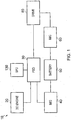
- FIG. 1 illustrates power elements of a typical hybrid vehicle, generally 10.
- the hybrid vehicle 10 is powered by an internal combustion engine 20 and a regenerative power assembly comprising a first motor generator 40, a battery 50 and a second motor generator 60.
- the internal combustion engine 20 is coupled with a power split device 30.
- Also coupled with the power split device 30 is the regenerative power assembly and a vehicle drive unit 80, such as the road wheels.
- the first motor generator 40 is coupled with the power split device 30 and the battery 50.
- the battery 50 is coupled with the second motor generator 60.
- the second motor generator 60 is coupled via a further power transfer path with the vehicle drive unit 80.
- the power split device 30 controls the distribution of power between the internal combustion engine 20, the first motor generator 40 and the vehicle drive unit 80 by varying an axial separation of race components of the power split device 30, as will be explained in more detail below.
- the power split device 30 is controlled by a set-point unit 130 which determines the axial separation of the race components and thus the power split ratio between the power elements.
- the power split device 30 is operated in any one of a number of different operating modes which are selected based upon the current operating condition of the vehicle and the demands of the driver, as will also be explained in more detail below.
- the set-point unit 130 controls the power distribution of the power split device 30 in order to maximise the overall efficiency of the hybrid vehicle 10 by operating the power elements as near to their optimal efficiency for the current conditions as is possible.
- the power split device 30 can be considered to be analogous to an epicyclic transmission that can vary the ratio between each of the three components to allow each of these components to operate nearer to their respective optimal efficiencies.
- the power split device 30 operates as a floating three element epicyclic transmission having a variable ratio.
- utilising the power split device 30 as an epicyclic transmission allows the operating envelope to be extended due to the variable ratio capacity of the power split device.
- the combination of the internal combustion engine 20, the vehicle drive unit 80, the regenerative power assembly and the power split device 30 can be considered to be analogous to an infinitely variable transmission.
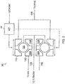
- FIG. 2 schematically illustrates in more detail the mechanical configuration of key components of the power split device 30.
- the power split device 30 comprises a radially inner race 100, a radially outer race 110 and, typically, three planetary members in rolling contact with both the inner race 100 and outer race 110.
- the planetary members each engage with a planet follower (not shown).
- the inner race 100 is comprised of two axially spaced components which are axially moveable relative to each other.
- the outer race 110 is composed of two axially spaced components, also axially moveable relative to each other. Varying the axial separation of the components of the inner race 100 and/or the outer race 110 causes the planetary members to move radially within these races and varies the gear ratio of the power split device.
- the planets followers are coupled via a engine spindle 125 with the internal combustion engine 20
- the inner race 100 is coupled via a motor generator spindle 105 with the motor generator 40
- the outer race 110 is coupled via a drive spindle 115 with the vehicle drive unit 80.
- each of the inner race, outer race and planets are free to rotate, rather than having at least one fixed component.
- the engine spindle 125 and the motor generator spindle 105 are arranged to rotate concentrically. This provides a particularly compact and efficient arrangement.
- the spindles 105, 115, 125 may be coupled with its associated power element via a transmission component such as a gear train, a clutch and/or a brake.
- the power split device 30 also comprises an actuator 180 operable to vary the axial separation of the components of the outer race 110.
- the components of the inner race 100 are resiliently spring to vary their axial separation in response to pressure from the planetary members 120, which varies the gear ratio of the power split device 30.
- the inner race 100 comprises two race components 100A, 100B which are engaged to the motor generator spindle 105 by means of a coupling comprising a helical interengagement in the form of a screw threaded engagement.
- the two race components 100A, 100B have oppositely handed threads so that a relative rotation of the motor generator spindle 105 and two race components 100A, 100B in one directional sense will cause the two components to be displaced towards one another whereas axial separation of the two race components 100A, 100B of the inner race 100 occurs where there is relative rotation between them and the motor generator spindle 105 in the opposite directional sense.
- the actuator 180 controls the axial separation of the components in response to a set-point signal provided by the set-point unit 130 and described in more detail below.
- FIG. 3 illustrates the set-point unit 130 in more detail.
- the set-point unit 130 is typically implemented as a microprocessor having associated memory or as a state machine.
- the set-point unit 130 receives a number of inputs from sensors within the hybrid vehicle 10 and outputs a set-point signal which controls the axial separation of the components of the outer race 110, an internal combustion engine control signal which controls the load of the internal combustion engine 20 and a motor generator engine control signal which controls the load of the motor generator 40 to maximise the efficiency of the hybrid vehicle 10.
- the sensory inputs provided to the set-point unit 30 include the speed of the internal combustion engine 20, the speed of the motor generator 40, and the speed of the hybrid vehicle 10.
- the set-point unit 130 is provided with details of the current demand being made by the driver of the hybrid vehicle 10, such as whether the driver is requesting more, the same or less power, as well as whether the driver wishes to slow the vehicle by braking, these signals are typically from accelerator pedal position sensors and brake pedal force sensors.
- the set-point unit 130 executes an algorithm which determines an optimal axial separation of the components of the outer race 110, together with an internal combustion engine loading and/or a motor generator engine loading, where appropriate, to improve the efficiency of the hybrid vehicle 10 under the current operating conditions.
- Figures 4a to 4d illustrate different operating modes of the power split device 30.
- the operating mode is determined based on the sensor information provided to the set-point unit 130.
- Figure 4a illustrates the power flow during a regenerative braking mode. This mode is sensed when the driver demand input to the set-point unit 130 indicates that the driver wishes to slow the vehicle and the engine fuelling demand is at a minimum.
- the set-point unit 130 determines the current rotation speed of the drive spindle 115 based on the vehicle speed information and utilises an algorithm to determine an axial separation of the components of the outer race 110 to provide a gear ratio which provides a substantially zero rotation speed for the engine spindle 125 whilst driving the motor generator spindle 105 at a speed which maximises the generator efficiency based on the efficiency characteristics as shown in, for example, Figure 8 .
- the set-point unit 130 outputs a set-point signal to the actuator 180 to achieve this axial separation.
- the algorithm constantly adjusts the axial separation of the race components and in so doing adjusts the gear ratio to best satisfy these demands as closely as possible.
- substantially no power is provided to the internal combustion engine 20 during braking and the power from the vehicle drive unit 80 is transferred to the motor generator 40 at a speed which optimises the efficiency of the motor generator 40.
- minimal power is provided to the internal combustion engine 20 and instead maximum power is transferred to the motor generator 40 for storage in the battery 50.
- Figure 4b illustrates the power flow during a moving, high state of charge mode.
- This mode is sensed when the driver demand input to the set-point unit 130 indicates that the driver wishes power to be applied to the vehicle drive unit 80, the vehicle speed information indicates that the vehicle speed is relatively high and the battery state of charge information indicates excess energy is available from the battery 50.
- both the internal combustion engine 20 and the motor generator 40 are utilised to provide power to the drive unit 80.
- the set-point unit 130 determines the internal combustion engine speed and the motor generator speed as well as the vehicle speed and utilises an algorithm to optimise the efficiency of the internal combustion engine 20 and the motor generator 40 to achieve the desired vehicle speed.
- the set-point unit 130 outputs a set-point signal to the actuator 180 to achieve this axial separation, together with an internal combustion engine control signal to achieve the desired load of the internal combustion engine 20 and/or a motor generator engine control signal to achieve the desired load of of the motor generator 40, where appropriate.
- the internal combustion engine control signal is utilised by an internal combustion engine control unit (not shown) to control the internal combustion engine load using its throttle, fuel injection of other means depending on its type.
- the motor generator control signal is utilised by a motor generator control unit (not shown) to control the motor generator load, typically by controlling motor current.
- a motor generator control unit (not shown) to control the motor generator load, typically by controlling motor current.
- the algorithm may apply weightings to favour operating either the internal combustion engine 20 or the motor generator 40 at their most efficient speeds. In general, where high fuel efficiency is desired, the algorithm will favour operating the internal combustion engine 20 at its most efficient point.
- Figure 4c illustrates the power flow during a moving, low state of charge mode.
- This mode is sensed when the driver demand input to the set-point unit 130 indicates that the driver wishes power to be applied to the vehicle drive unit 80 and the battery state of charge information indicates the battery 50 is low on energy.
- the internal combustion engine 20 is utilised to provide power to the drive unit 80 and the motor generator 40.
- the set-point unit 130 changes the axial separation of the race components of the outer race 110 to operate the internal combustion engine 20 at its most efficient speed and to divert some of the excess power away from the drive unit 80 and into the motor generator 40.
- the set-point unit 130 outputs a set-point signal to the actuator 180 to achieve this axial separation, together with an internal combustion engine control signal to achieve the desired load of the internal combustion engine 20.
- the algorithm will seek to drive the motor generator 40 at the most efficient speed possible, once again a weighting will typically be applied to favour operating the internal combustion engine 20 at its most efficient speed. In this way, it can be seen that the axial separation of the race components of the outer race 110 of the power split device 30 can be varied to divert power from the internal combustion engine 20 when operating at its most efficient point and into the regenerative power assembly.
- Figure 4d illustrates the power flow during a zero emission mode.
- This mode is sensed when the driver demand input to the set-point unit 130 indicates that the driver wishes power to be applied to the vehicle drive unit 80, the vehicle speed information indicates that the vehicle speed is relatively low and the battery state of charge information indicates excess energy is available from the battery 50.
- the motor generator 40 is utilised to provide power to the derive unit 80.
- the set-point unit 130 changes the axial separation of the components of the outer race 110 to enable the internal combustion engine 20 to be switched off and power to be supplied from the motor generator 40 instead.
- the set-point unit 130 outputs a set-point signal to the actuator 180 to achieve this axial separation, together with a motor generator engine control signal to achieve the desired load of of the motor generator 40.
- the axial separation will be set to attempt to operate the motor generator 40 at the most efficient speed possible for the current conditions.
- the variable ratio provided by the power split device 30, enable the motor generator 40 to be utilised to propel the hybrid vehicle 10 for a much wider range of speeds than would otherwise be possible.
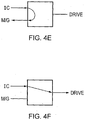
- Figure 4e illustrates the power flow during a stationary, low state of charge mode.
- This mode is sensed when the driver demand input to the set-point unit 130 indicates that the vehicle 10 is stationary and the battery state of charge information indicates the battery 50 is low on energy.
- the internal combustion engine 20 is utilised to provide power to the motor generator 40.
- the set-point unit 130 changes the axial separation of the race components of the outer race 110 to operate the internal combustion engine 20 at its most efficient speed and supply the excess power into the motor generator 40 with substantially no power being supplied to the vehicle drive unit 80.
- the set-point unit 130 outputs a set-point signal to the actuator 180 to achieve this axial separation, together with an internal combustion engine control signal to achieve the desired load of the internal combustion engine 20.
- the algorithm will seek to drive the motor generator 40 at the most efficient speed possible, once again a weighting will typically be applied to favour operating the internal combustion engine 20 at its most efficient speed. In this way, it can be seen that the axial separation of the race components of the outer race 110 of the power split device 30 can be varied to provide power from the internal combustion engine 20 when operating at its most efficient point into the regenerative power assembly.
- Figure 4f illustrates the power flow during a moving, low state of charge mode.
- This mode is sensed when the driver demand input to the set-point unit 130 indicates that the driver wishes power to be applied to the vehicle drive unit 80, the vehicle speed information indicates that the vehicle speed is relatively high and the battery state of charge information indicates no excess energy is available from the battery 50.
- the set-point unit 130 determines the internal combustion engine speed as well as the vehicle speed and utilises an algorithm to optimise the efficiency of the internal combustion engine 20 to achieve the desired vehicle speed.
- the set-point unit 130 outputs a set-point signal to the actuator 180 to achieve this axial separation, together with an internal combustion engine control signal to achieve the desired load of the internal combustion engine 20.
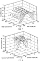
- Figure 5 illustrates the speed ratio relationship between elements of a typical power split device 30.
- ⁇ carrier R cont , in ⁇ in + R planet , in R cont , out R planet , out ⁇ outer R cont , in + R planet , in R cont , out R planet , out , where the values of radius all vary depending on the specific design geometry and current instantaneous speed ratio of the power split device 30.
- Each of the planes of the graph in Figure 5 shows the relationship at one particular discrete ratio.
- the graph shows how the iso-ratio conditions pass through each other when all the components become synchronous.
- the upper and lower planes of the graph show a complete envelope of relationships possible at different axial separations of the races.
- the ratio of the power split device 30 dictates the tilt angle of each of the iso-ratio planes. This information is stored by the set-point unit 130 and is utilised by its algorithms. It will be appreciated that a fixed ratio epicyclic gear train would only be able to achieve one of these planes, rather than the operating envelope contained within the upper and lower bounding planes.
- Figure 6 illustrates the power flow on each component of the power split device 30 assuming a unity torque applied to the inner race 100.
- the power split device 30 acts as a summing junction for power transmitted (as would be the case with a fixed ratio epicyclic), although the variable ratio nature of the power split device 30 allows this power split to be varied significantly thus allowing more or less engine power to be delivered to either the electric elements or mechanical elements of the hybrid vehicle 10.
- this information is stored by the set-point unit 130 and utilised by its algorithms.
- Figure 7 illustrates typical motor efficiency characteristics or the motor generator 40. There is a rapid degradation in electric machine efficiency it is operated away from ideal operating points. Significant overall vehicle efficiency may be achieved by controlling the electric machines to operate at speed and torque conditions that improve their efficiencies. The variable ratio provided by the power split device 30 allows this improved control to be achieved. These characteristics are also stored by the set-point unit 130 and utilised by its algorithms.
- Figure 8 illustrates generator efficiency characteristics of the motor generator 40. This information is stored by the set-point unit 130 and utilised by its algorithms.
- Figure 9 illustrates typical efficiency characteristics of the internal combustion engine 20. The efficiency is described by Brake specific fuel consumption contours. As can be seen the internal combustion engine 20 operates near its peak efficiency when at low speed and high load. Again, this information is stored by the set-point unit 130 and utilised by its algorithms.
- this arrangement can be utilised to enable a hybrid vehicle 10 to operate at higher road speeds without having to activate the internal combustion engine 20 through the use of the variable gearing provided by the power split device 30. This reduces the amount of carbon emissions made by the vehicle. Also, the variable ratio nature of the power split device 30 enables the internal combustion engine 20 and machine generator 40 to be operated under conditions which better match each units individual characteristics and improve their efficiency.
Landscapes
- Engineering & Computer Science (AREA)
- Chemical & Material Sciences (AREA)
- Combustion & Propulsion (AREA)
- Mechanical Engineering (AREA)
- Transportation (AREA)
- General Engineering & Computer Science (AREA)
- Automation & Control Theory (AREA)
- Electric Propulsion And Braking For Vehicles (AREA)
- Hybrid Electric Vehicles (AREA)
- Friction Gearing (AREA)
- Transmission Devices (AREA)
- Control Of Vehicle Engines Or Engines For Specific Uses (AREA)
Description
- The present invention relates to a power split device and method.
- In multiple-power source devices, such as, for example, hybrid vehicles, arrangements exist to distribute power between elements of the vehicle. For example, it is known in a so-called parallel hybrid vehicle to provide a planetary gear power train which links an internal combustion engine, the driven road wheels and any electric machines. The planetary gear hybrid power train provides two power paths between the internal combustion engine and the driven road wheels. The first power path may be a mechanical coupling between the internal combustion engine and the driven wheels, whilst the second power path may be via a motor-generator and battery arrangement.
- This approach enables the two power paths to be utilised under different conditions to improve the overall efficiency of the vehicle. However, whilst the planetary gear power train is simple and fairly efficient it suffers from a number of limitations. Accordingly, it is desired to provide an improved power split.
-
WO 99/35417 -
US 2005/0113202 discloses continuously variable planetary gear sets. In one arrangement, a combustion engine provides an input to a cage which retains tiltable planets which are placed between two discs. A motor provides torque to the input disc and power is taken from the output disc. - According to a first aspect to the present invention there is provided a variable ratio power split device as claimed in
claim 1. - The first aspect recognises that a limitation with the planetary gear hybrid power train mentioned above is that the elements coupled with the planetary gear hybrid power train are often not operating efficiently. For example, the internal combustion engine must always operate when the driven road wheels rotate above certain speeds which limits the potential of the vehicle to reduce emissions. Furthermore, the speed of the motor generators is directly dependent upon the speed of the internal combustion engine and/or the driven road wheels. Hence, it is unlikely that for any particular operating condition, the elements coupled with the power train can be operated efficiently. This is because the planetary gear hybrid power provides is a fixed power split ratio between the elements.
- Accordingly, a variable ratio power split device is provided having inner and outer races, planetary members and a planet follower carrier is provided. Rotatable power element spindles are connected to each of the races and the planet follower carrier to couple power with respective power elements. By adjusting the axial separation of one of the races, the ratio of power distributed between the power element spindles is varied which improves the operability of the device. The axial separation may be adjusted to enable minimal power to be coupled to any of the first, second or third power elements. Power may then be distributed between the remaining two power elements without any power being provided to the third.
- In one embodiment, the set-point unit is operable to determine, with reference to stored data indicative of the predetermined efficiency characteristics, an axial separation of the axially spaced parts of at least one of the races to provide a power split ratio which improves an operating efficiency of at least one of the first, second and third power elements under the current operating conditions.
- The sensors enable the current conditions to be established. By u sing knowledge of the characteristics of the power elements, an appropriate relationship of power distribution between the power elements can be set by adjusting the axial separation of the races. In this way, the differing operating requirements of the power element under the current operating conditions can be better balanced to improve the efficiency of at least one of the power elements.
- In one embodiment, the device comprises: a plurality of the sensors and the set-point unit is operable to determine, with reference to the stored data indicative of the predetermined efficiency characteristics, an axial separation of the axially spaced parts of at least one of the races to provide a power split ratio which improves an operating efficiency of more than one of the first, second and third power elements under the current operating conditions.
- Accordingly, the axial separation may be varied to provide an optimised efficiency of more than one of the power elements for the current operating conditions. It will be appreciated that in doing so the absolute optimum efficiency of one of the power elements may need to be reduced slightly in order to provide a significantly improved efficiency of one of the other power elements and thereby improve the overall efficiency of power elements coupled to the variable ratio power split device.
- It will be appreciated that the vehicle transmission assembly may be a vehicle drive train.
- It will be appreciated that these assemblies may store power in a variety of ways such as, for example, mechanically, kinetically, chemically and hydraulically.
- In one embodiment, the at least one of the power transmission assembly and the vehicle transmission assembly is operable to reapply the stored energy.
- Hence, the stored energy may be recovered from these assemblies and reused subsequently.
- In one embodiment, the variable ratio power split device comprises a further power coupling and wherein the at least one of the power transmission assembly and the vehicle transmission assembly is operable to reapply the stored power via the further power coupling.
- Accordingly, a separate path may exist whereby any power stored by these assemblies may be applied to each other, other than via the variable ratio power split device. For example, the power transmission assembly may store power and apply this directly to the vehicle transmission assembly via a power coupling other than by way of the planetary members to enable the power stored to be directly applied to the vehicle transmission assembly.
- In one embodiment, the set-point unit is operable in any one of a number of modes and, when in a regenerative mode, is operable to determine, with reference to the stored data indicative of the predetermined efficiency characteristics, an axial separation of the axially spaced parts of at least one of the races to provide a power split ratio which causes minimal power to be coupled to the internal combustion engine and power from the vehicle transmission assembly to be provided to the regenerative power assembly at a speed which improves an operating efficiency of the regenerative power assembly under current operating conditions.
- When in a regenerative or power storing mode, energy from the vehicle transmission assembly is diverted to the regenerative power assembly, typically to slow a vehicle, and the kinetic energy of the vehicle is then stored as potential energy in the regenerative power assembly. Typically, in such a mode it is desirable for minimal energy to be provided by the internal combustion engine, which may be inactivated during such braking. Also, it is desirable to operate the regenerative power assembly at a speed which maximises the efficiency of this power storage. Accordingly, the axial separation of the races is adjusted in order to minimise any power being provided by or to the internal combustion engine and to operate the regenerative power assembly at a near constant efficient speed as the speed of the vehicle and hence the speed of the vehicle transmissions assembly reduces.
- In one embodiment, the set-point unit is operable in any one of a number of modes and, when in a moving, high state of charge mode, is operable to determine, with reference to the stored data indicative of the predetermined efficiency characteristics, an axial separation of the axially spaced parts of at least one of the races to provide a power split ratio which causes power to be coupled from the internal combustion engine and the regenerative power assembly to the vehicle transmission assembly at a speed which improves an operating efficiency of at least one of the internal combustion engine and the regenerative power assembly under current operating conditions.
- When the regenerative power assembly is in a high state of charge, there is little requirement to store any further energy in the regenerative power assembly. Accordingly, power can be utilised from both the internal combustion engine and the regenerative power supply, and applied to the vehicle transmission assembly to propel the vehicle as required. Hence, the axial separation of the races is adjusted to operate either and/or both the internal combustion engine and the regenerative power supply at a speed which improves their operating efficiency as the speed of the vehicle changes.
- In one embodiment, the set-point unit is operable in any one of a number of modes and, when in a moving, low state of charge mode, is operable to determine, with reference to the stored data indicative of the predetermined efficiency characteristics, an axial separation of the axially spaced parts of at least one of the races to provide a power split ratio which causes power to be coupled from the internal combustion engine to the regenerative power assembly and the vehicle transmission assembly at a speed which improves an operating efficiency of at least one of the internal combustion engine and the regenerative power assembly under current operating conditions.
- When the regenerative power assembly is in a low state of charge, any excess energy from the internal combustion energy may be converted to improve the state of charge of the regenerative power assembly. Accordingly, the axial separation of the races is adjusted to enable power to be supplied to the regenerative power supply at a speed which improves the operating efficiency of the regenerative power supply and/or the internal combustion engine.
- In one embodiment, the set-point unit is operable in any one of a number of modes and, when in a zero emissions mode, is operable to determine, with reference to the stored data indicative of the predetermined efficiency characteristics, an axial separation of the axially spaced parts of at least one of the races to provide a power split ratio which causes minimal power to be coupled to the internal combustion engine and power from the regenerative power assembly to be provided to the vehicle transmission assembly at a speed which improves an operating efficiency of the regenerative power assembly under current operating conditions.
- Hence, when it is desired to emit no emissions from the internal combustion engine, the axial separation of the races is set such that minimal power is provided from the internal combustion energy and the power for the vehicle transmission assembly is provided by the regenerative power assembly. Hence, the regenerative power assembly is operated at a speed which maximises the efficiency of the power provided by the regenerative power assembly based on the speed of the vehicle transmission assembly, whilst minimising any power from the internal combustion energy, which may be switched off.
- In one embodiment, the set-point unit is operable in any one of a number of modes and, when in a stationary, low state of charge mode, is operable to determine, with reference to the stored data indicative of the predetermined efficiency characteristics, an axial separation of the axially spaced parts of at least one of the races to provide a power split ratio which causes minimal power to be provided to the vehicle transmission assembly and power from the internal combustion engine to be provided to the regenerative power assembly at a speed which improves an operating efficiency at least one of the internal combustion engine and the regenerative power assembly under current operating conditions.
- When the regenerative power assembly is in a low state of charge and the vehicle is not moving, energy from the internal combustion energy may be converted to improve the state of charge of the regenerative power assembly. Accordingly, the axial separation of the races is adjusted to enable power to be supplied to the regenerative power supply at a speed which improves the operating efficiency of the regenerative power supply and/or the internal combustion engine.
- In one embodiment, the set-point unit is operable in any one of a number of modes and, when in a moving, low state of charge mode, is operable to determine, with reference to the stored data indicative of the predetermined efficiency characteristics, an axial separation of the axially spaced parts of at least one of the races to provide a power split ratio which causes minimal power to be provided to the regenerative power assembly and power from the internal combustion engine to be provided to the vehicle transmission assembly at a speed which improves an operating efficiency of the internal combustion engine under current operating conditions.
- When the regenerative power assembly is in a low state of charge, there is excess energy available in the regenerative power assembly. Accordingly, power can only be utilised from the internal combustion engine and applied to the vehicle transmission assembly to propel the vehicle as required. Hence, the axial separation of the races is adjusted to operate the internal combustion engine at a speed which improves its operating efficiency as the speed of the vehicle changes.
- In one embodiment, the variable ratio power split device comprises: a transmission component and wherein at least one of the first, second and third rotatable power element spindles are connected with the transmission component.
- Accordingly, a component may be provided between the power element spindles and the power elements.
- In one embodiment, the transmission component comprises at least one of a gear train, a clutch and a brake.
- In one embodiment, the first and second power element spindles are concentrically rotatable.
- Providing concentrically rotatable spindles achieves a simple and compact construction of the variable ratio power split device whilst enabling power to be distributed between each the three power elements.
- In one embodiment, the variable ratio power split device comprises: the first power element connected with the first rotatable power element spindle; the second power element connected with the second rotatable power element spindle; and the third power element connected with the third power element spindle.
- According to a second aspect of the present invention, there is provided a method of varying power, as claimed in claim 13.
- In embodiments, there are provided method steps performed by the corresponding features of the first aspect.
- Embodiments of the present invention will now be described with reference to the accompanying drawings in which:
-
Figure 1 illustrates a hybrid vehicle incorporating a power split device according to one embodiment; -
Figure 2 illustrates the mechanical arrangement of the power split device ofFigure 1 in more detail; -
Figure 3 illustrates a set-point unit of the power split device; -
Figures 4a to 4f illustrate schematically power flows of the power split device when operating in different modes; -
Figure 5 is a graph showing an example relationship between the rotational speed of the components of the power split device when operating at any one of a number of different gearing ratios; -
Figure 6 illustrates an example power flow on each component of the power split device; -
Figure 7 shows an example motor efficiency characteristic a typical permanent magnet motor/generator; -
Figure 8 shows an example generator efficiency characteristics of the typical permanent magnet motor/generator; and -
Figure 9 illustrates an example efficiency characteristic of a typical internal combustion engine. -
Figure 1 illustrates power elements of a typical hybrid vehicle, generally 10. Thehybrid vehicle 10 is powered by aninternal combustion engine 20 and a regenerative power assembly comprising afirst motor generator 40, abattery 50 and asecond motor generator 60. Theinternal combustion engine 20 is coupled with apower split device 30. Also coupled with thepower split device 30 is the regenerative power assembly and avehicle drive unit 80, such as the road wheels. - The
first motor generator 40 is coupled with thepower split device 30 and thebattery 50. Thebattery 50 is coupled with thesecond motor generator 60. Thesecond motor generator 60 is coupled via a further power transfer path with thevehicle drive unit 80. - The power split
device 30 controls the distribution of power between theinternal combustion engine 20, thefirst motor generator 40 and thevehicle drive unit 80 by varying an axial separation of race components of thepower split device 30, as will be explained in more detail below. The power splitdevice 30 is controlled by a set-point unit 130 which determines the axial separation of the race components and thus the power split ratio between the power elements. The power split device 30.is operated in any one of a number of different operating modes which are selected based upon the current operating condition of the vehicle and the demands of the driver, as will also be explained in more detail below. The set-point unit 130 controls the power distribution of thepower split device 30 in order to maximise the overall efficiency of thehybrid vehicle 10 by operating the power elements as near to their optimal efficiency for the current conditions as is possible. Hence, thepower split device 30 can be considered to be analogous to an epicyclic transmission that can vary the ratio between each of the three components to allow each of these components to operate nearer to their respective optimal efficiencies. In other words, thepower split device 30 operates as a floating three element epicyclic transmission having a variable ratio. Utilising thepower split device 30 as an epicyclic transmission allows the operating envelope to be extended due to the variable ratio capacity of the power split device. Also, the combination of theinternal combustion engine 20, thevehicle drive unit 80, the regenerative power assembly and thepower split device 30 can be considered to be analogous to an infinitely variable transmission. - Although the power elements of the
hybrid vehicle 10 have been shown schematically as being coupled with each other, it will be appreciated that transmission components may be provided therebetween in order to provide for further power transmission control. -
Figure 2 schematically illustrates in more detail the mechanical configuration of key components of thepower split device 30. The power splitdevice 30 comprises a radiallyinner race 100, a radially outer race 110 and, typically, three planetary members in rolling contact with both theinner race 100 and outer race 110. The planetary members each engage with a planet follower (not shown). Theinner race 100 is comprised of two axially spaced components which are axially moveable relative to each other. Similarly, the outer race 110 is composed of two axially spaced components, also axially moveable relative to each other. Varying the axial separation of the components of theinner race 100 and/or the outer race 110 causes the planetary members to move radially within these races and varies the gear ratio of the power split device. Such an arrangement is shown generally inWO 99/35417 engine spindle 125 with theinternal combustion engine 20, theinner race 100 is coupled via amotor generator spindle 105 with themotor generator 40 and the outer race 110 is coupled via adrive spindle 115 with thevehicle drive unit 80. Hence, each of the inner race, outer race and planets are free to rotate, rather than having at least one fixed component. In this arrangement, theengine spindle 125 and themotor generator spindle 105 are arranged to rotate concentrically. This provides a particularly compact and efficient arrangement. Also, as described in more detail below, thespindles - The power split
device 30 also comprises anactuator 180 operable to vary the axial separation of the components of the outer race 110. The components of theinner race 100 are resiliently spring to vary their axial separation in response to pressure from theplanetary members 120, which varies the gear ratio of thepower split device 30. In particular, theinner race 100 comprises tworace components motor generator spindle 105 by means of a coupling comprising a helical interengagement in the form of a screw threaded engagement. The tworace components motor generator spindle 105 and tworace components race components inner race 100 occurs where there is relative rotation between them and themotor generator spindle 105 in the opposite directional sense. Theactuator 180 controls the axial separation of the components in response to a set-point signal provided by the set-point unit 130 and described in more detail below. - Hence, it can be seen that power can be distributed by the
races 100, 110 andplanetary members 120 of the power-split device 30 between theinternal combustion engine 20, themotor generators 40 and thedrive unit 80 via their respective spindles. Varying the axial separation of the components varies the ratio of power distribution between these components. -
Figure 3 illustrates the set-point unit 130 in more detail. The set-point unit 130 is typically implemented as a microprocessor having associated memory or as a state machine. The set-point unit 130 receives a number of inputs from sensors within thehybrid vehicle 10 and outputs a set-point signal which controls the axial separation of the components of the outer race 110, an internal combustion engine control signal which controls the load of theinternal combustion engine 20 and a motor generator engine control signal which controls the load of themotor generator 40 to maximise the efficiency of thehybrid vehicle 10. Among the sensory inputs provided to the set-point unit 30 include the speed of theinternal combustion engine 20, the speed of themotor generator 40, and the speed of thehybrid vehicle 10. Also provided to the set-point unit is the current state of charge of thebattery 50, as well as the current engine fuelling arrangements for theinternal combustion engine 20. Additionally, the set-point unit 130 is provided with details of the current demand being made by the driver of thehybrid vehicle 10, such as whether the driver is requesting more, the same or less power, as well as whether the driver wishes to slow the vehicle by braking, these signals are typically from accelerator pedal position sensors and brake pedal force sensors. - The set-
point unit 130 executes an algorithm which determines an optimal axial separation of the components of the outer race 110, together with an internal combustion engine loading and/or a motor generator engine loading, where appropriate, to improve the efficiency of thehybrid vehicle 10 under the current operating conditions. -
Figures 4a to 4d illustrate different operating modes of thepower split device 30. The operating mode is determined based on the sensor information provided to the set-point unit 130. -
Figure 4a illustrates the power flow during a regenerative braking mode. This mode is sensed when the driver demand input to the set-point unit 130 indicates that the driver wishes to slow the vehicle and the engine fuelling demand is at a minimum. When in this mode, the set-point unit 130 determines the current rotation speed of thedrive spindle 115 based on the vehicle speed information and utilises an algorithm to determine an axial separation of the components of the outer race 110 to provide a gear ratio which provides a substantially zero rotation speed for theengine spindle 125 whilst driving themotor generator spindle 105 at a speed which maximises the generator efficiency based on the efficiency characteristics as shown in, for example,Figure 8 . The set-point unit 130 outputs a set-point signal to theactuator 180 to achieve this axial separation. As the vehicle slows the algorithm constantly adjusts the axial separation of the race components and in so doing adjusts the gear ratio to best satisfy these demands as closely as possible. In this way, substantially no power is provided to theinternal combustion engine 20 during braking and the power from thevehicle drive unit 80 is transferred to themotor generator 40 at a speed which optimises the efficiency of themotor generator 40. Hence, during regenerative braking minimal power is provided to theinternal combustion engine 20 and instead maximum power is transferred to themotor generator 40 for storage in thebattery 50. -
Figure 4b illustrates the power flow during a moving, high state of charge mode. This mode is sensed when the driver demand input to the set-point unit 130 indicates that the driver wishes power to be applied to thevehicle drive unit 80, the vehicle speed information indicates that the vehicle speed is relatively high and the battery state of charge information indicates excess energy is available from thebattery 50. When in this mode both theinternal combustion engine 20 and themotor generator 40 are utilised to provide power to thedrive unit 80. Hence, the set-point unit 130 determines the internal combustion engine speed and the motor generator speed as well as the vehicle speed and utilises an algorithm to optimise the efficiency of theinternal combustion engine 20 and themotor generator 40 to achieve the desired vehicle speed. This is achieved by varying the axial separation of the race components of the outer race 110 in order to vary the power provided by both theinternal combustion engine 20 and themotor generator 40, together with varying the load of theinternal combustion engine 20 and the load of themotor generator 40 in order to operate these at close to their optimal efficiency. The set-point unit 130 outputs a set-point signal to theactuator 180 to achieve this axial separation, together with an internal combustion engine control signal to achieve the desired load of theinternal combustion engine 20 and/or a motor generator engine control signal to achieve the desired load of of themotor generator 40, where appropriate. The internal combustion engine control signal is utilised by an internal combustion engine control unit (not shown) to control the internal combustion engine load using its throttle, fuel injection of other means depending on its type. The motor generator control signal is utilised by a motor generator control unit (not shown) to control the motor generator load, typically by controlling motor current. By varying the axial separation of the components of the outer race 110 the operating speed of theinternal combustion engine 20 and themotor generator 40 can be changed such that they operate closer to the most efficient speeds. Clearly, where the demands are such that both cannot possibly be operated at their most efficient then the algorithm may apply weightings to favour operating either theinternal combustion engine 20 or themotor generator 40 at their most efficient speeds. In general, where high fuel efficiency is desired, the algorithm will favour operating theinternal combustion engine 20 at its most efficient point. -
Figure 4c illustrates the power flow during a moving, low state of charge mode. This mode is sensed when the driver demand input to the set-point unit 130 indicates that the driver wishes power to be applied to thevehicle drive unit 80 and the battery state of charge information indicates thebattery 50 is low on energy. When in this mode theinternal combustion engine 20 is utilised to provide power to thedrive unit 80 and themotor generator 40. Accordingly, the set-point unit 130 changes the axial separation of the race components of the outer race 110 to operate theinternal combustion engine 20 at its most efficient speed and to divert some of the excess power away from thedrive unit 80 and into themotor generator 40. This is achieved by varying the axial separation of the race components of the outer race 110 in order to vary the power provided by theinternal combustion engine 20 to thevehicle drive unit 80 and themotor generator 40, together with varying the load of theinternal combustion engine 20. The set-point unit 130 outputs a set-point signal to theactuator 180 to achieve this axial separation, together with an internal combustion engine control signal to achieve the desired load of theinternal combustion engine 20. Although the algorithm will seek to drive themotor generator 40 at the most efficient speed possible, once again a weighting will typically be applied to favour operating theinternal combustion engine 20 at its most efficient speed. In this way, it can be seen that the axial separation of the race components of the outer race 110 of thepower split device 30 can be varied to divert power from theinternal combustion engine 20 when operating at its most efficient point and into the regenerative power assembly. -
Figure 4d illustrates the power flow during a zero emission mode. This mode is sensed when the driver demand input to the set-point unit 130 indicates that the driver wishes power to be applied to thevehicle drive unit 80, the vehicle speed information indicates that the vehicle speed is relatively low and the battery state of charge information indicates excess energy is available from thebattery 50. When in this mode themotor generator 40 is utilised to provide power to the deriveunit 80. Accordingly, the set-point unit 130 changes the axial separation of the components of the outer race 110 to enable theinternal combustion engine 20 to be switched off and power to be supplied from themotor generator 40 instead. The set-point unit 130 outputs a set-point signal to theactuator 180 to achieve this axial separation, together with a motor generator engine control signal to achieve the desired load of of themotor generator 40. The axial separation will be set to attempt to operate themotor generator 40 at the most efficient speed possible for the current conditions. The variable ratio provided by thepower split device 30, enable themotor generator 40 to be utilised to propel thehybrid vehicle 10 for a much wider range of speeds than would otherwise be possible. -
Figure 4e illustrates the power flow during a stationary, low state of charge mode. This mode is sensed when the driver demand input to the set-point unit 130 indicates that thevehicle 10 is stationary and the battery state of charge information indicates thebattery 50 is low on energy. When in this mode theinternal combustion engine 20 is utilised to provide power to themotor generator 40. Accordingly, the set-point unit 130 changes the axial separation of the race components of the outer race 110 to operate theinternal combustion engine 20 at its most efficient speed and supply the excess power into themotor generator 40 with substantially no power being supplied to thevehicle drive unit 80. This is achieved by varying the axial separation of the race components of the outer race 110 in order to vary the power provided by theinternal combustion engine 20 to thevehicle drive unit 80 and themotor generator 40, together with varying the load of theinternal combustion engine 20. The set-point unit 130 outputs a set-point signal to theactuator 180 to achieve this axial separation, together with an internal combustion engine control signal to achieve the desired load of theinternal combustion engine 20. Although the algorithm will seek to drive themotor generator 40 at the most efficient speed possible, once again a weighting will typically be applied to favour operating theinternal combustion engine 20 at its most efficient speed. In this way, it can be seen that the axial separation of the race components of the outer race 110 of thepower split device 30 can be varied to provide power from theinternal combustion engine 20 when operating at its most efficient point into the regenerative power assembly. -
Figure 4f illustrates the power flow during a moving, low state of charge mode. This mode is sensed when the driver demand input to the set-point unit 130 indicates that the driver wishes power to be applied to thevehicle drive unit 80, the vehicle speed information indicates that the vehicle speed is relatively high and the battery state of charge information indicates no excess energy is available from thebattery 50. When in this mode only theinternal combustion engine 20 is utilised to provide power to thedrive unit 80. Hence, the set-point unit 130 determines the internal combustion engine speed as well as the vehicle speed and utilises an algorithm to optimise the efficiency of theinternal combustion engine 20 to achieve the desired vehicle speed. This is achieved by varying the axial separation of the race components of the outer race 110 in order to vary the power provided by theinternal combustion engine 20, together with varying the load of theinternal combustion engine 20 in order to operate this at close to its optimal efficiency. The set-point unit 130 outputs a set-point signal to theactuator 180 to achieve this axial separation, together with an internal combustion engine control signal to achieve the desired load of theinternal combustion engine 20. By varying the axial separation of the components of the outer race 110, the operating speed of theinternal combustion engine 20 can be changed such that it operates closer to its most efficient speed. -
Figure 5 illustrates the speed ratio relationship between elements of a typicalpower split device 30. A traditional floating epicyclic gear train has 3 elements that rotate about the principle axis of the transmission, the sun, the carrier and the annulus. The speed of these elements are related to each other by the following relationship:

- For a typical existing hybrid vehicle, the epicyclic ratio is around 78/30= 2.6. Similarly the torque relationship is as follows:


- For the
power split device 30, the equation relating the speed of each element may be derived as:
power split device 30. The torque relationships on each element of thepower split device 30 are as follows:


- It will be appreciated that utilising the
power split device 30 as an epicyclic transmission allows the operating envelope of the hybrid vehicle to be extended further due to the variable ratio capability of thepower split device 30. - Each of the planes of the graph in
Figure 5 shows the relationship at one particular discrete ratio. The graph shows how the iso-ratio conditions pass through each other when all the components become synchronous. The upper and lower planes of the graph show a complete envelope of relationships possible at different axial separations of the races. The ratio of thepower split device 30 dictates the tilt angle of each of the iso-ratio planes. This information is stored by the set-point unit 130 and is utilised by its algorithms. It will be appreciated that a fixed ratio epicyclic gear train would only be able to achieve one of these planes, rather than the operating envelope contained within the upper and lower bounding planes. -
Figure 6 illustrates the power flow on each component of thepower split device 30 assuming a unity torque applied to theinner race 100. Clearly thepower split device 30 acts as a summing junction for power transmitted (as would be the case with a fixed ratio epicyclic), although the variable ratio nature of thepower split device 30 allows this power split to be varied significantly thus allowing more or less engine power to be delivered to either the electric elements or mechanical elements of thehybrid vehicle 10. Once again, this information is stored by the set-point unit 130 and utilised by its algorithms. -
Figure 7 illustrates typical motor efficiency characteristics or themotor generator 40. There is a rapid degradation in electric machine efficiency it is operated away from ideal operating points. Significant overall vehicle efficiency may be achieved by controlling the electric machines to operate at speed and torque conditions that improve their efficiencies. The variable ratio provided by thepower split device 30 allows this improved control to be achieved. These characteristics are also stored by the set-point unit 130 and utilised by its algorithms. -
Figure 8 illustrates generator efficiency characteristics of themotor generator 40. This information is stored by the set-point unit 130 and utilised by its algorithms. -
Figure 9 illustrates typical efficiency characteristics of theinternal combustion engine 20. The efficiency is described by Brake specific fuel consumption contours. As can be seen theinternal combustion engine 20 operates near its peak efficiency when at low speed and high load. Again, this information is stored by the set-point unit 130 and utilised by its algorithms. - As can be seen, this arrangement can be utilised to enable a
hybrid vehicle 10 to operate at higher road speeds without having to activate theinternal combustion engine 20 through the use of the variable gearing provided by thepower split device 30. This reduces the amount of carbon emissions made by the vehicle. Also, the variable ratio nature of thepower split device 30 enables theinternal combustion engine 20 andmachine generator 40 to be operated under conditions which better match each units individual characteristics and improve their efficiency. - Although particular embodiments have been described herein it would be apparent that the invention is not limited thereto and that many modifications and additions may be made within the scope of the invention as defined in the claims. For example, various combinations of features from the following dependent claims could be made with features of the independent claims without departing from the scope of the present invention.
Claims (13)
- A variable ratio power split device (30) comprising:radially inner (100) and outer races (110), each comprising at least two axially spaced parts (100A, 100B);a plurality of planetary members (120) arranged for rolling contact between said inner and outer races;a planet follower carrier engaging with said planetary members;a first rotatable power element spindle (125) which is connected with said planet follower and operable to couple power between said planet follower carrier and a first power element (20) comprising an internal combustion engine;a second rotatable power element spindle (105) which is connected with said inner race and operable to couple power between said inner race and a second power element (80) comprising a regenerative power assembly;a third rotatable power element spindle (115) which is connected with said outer race and operable to couple power between said outer race and a third power element (40) comprising a vehicle transmission assembly, wherein at least one of said power transmission assembly and said vehicle transmission assembly is operable to store energy, andwherein said at least one of said power transmission assembly and said vehicle transmission assembly is operable to reapply said stored energy;means for adjusting an axial separation of said axially spaced parts of at least one of said races to vary a power split ratio between said first, second and third rotatable power element spindles;at least one sensor operable to determine current operating conditions;a set-point unit (130) configured to determine, with reference to stored data indicative of predetermined efficiency characteristics of said first, second and third power elements under predetermined operating conditions, an axial separation of said axially spaced parts of at least one of said races to provide a power split ratio which causes substantially no power to be coupled to one of said first, second and third power elements under said current operating conditions;wherein said set-point unit is operable in any one of a number of modes and, when in a regenerative mode, is configured to determine, with reference to said stored data indicative of said predetermined efficiency characteristics, an axial separation of said axially spaced parts of at least one of said races to provide a power split ratio which causes minimal power to be coupled to said internal combustion engine and power from said vehicle transmission assembly to be provided to said regenerative power assembly at a speed which improves an operating efficiency of said regenerative power assembly under current operating conditions.
- The variable ratio power split device of claim 1, wherein said set-point unit is operable to determine, with reference to stored data indicative of said predetermined efficiency characteristics, an axial separation of said axially spaced parts of at least one of said races to provide a power split ratio which improves an operating efficiency of at least one of said first, second and third power elements under said current operating conditions.
- The variable ratio power split device of claim 2, comprising:a plurality of said sensors and wherein said set-point unit is operable to determine, with reference to said stored data indicative of said predetermined efficiency characteristics, an axial separation of said axially spaced parts of at least one of said races to provide a power split ratio which improves an operating efficiency of more than one of said first, second and third power elements under said current operating conditions.
- The variable ratio power split device as claimed in any preceding claim, comprising a further power coupling and wherein said at least one of said power transmission assembly and said vehicle transmission assembly is operable to reapply said stored power via said further power coupling.
- The variable ratio power split device of any preceding claim, wherein said set-point unit is operable in any one of a number of modes and, when in a moving, high state of charge mode, is operable to determine, with reference to said stored data indicative of said predetermined efficiency characteristics, an axial separation of said axially spaced parts of at least one of said races to provide a power split ratio which causes power to be coupled from said internal combustion engine and said regenerative power assembly to said vehicle transmission assembly at a speed which improves an operating efficiency of at least one of said internal combustion engine and said regenerative power assembly under current operating conditions.
- The variable ratio power split device of any preceding claim, wherein said set-point unit is operable in any one of a number of modes and, when in a moving, low state of charge mode, is operable to determine, with reference to said stored data indicative of said predetermined efficiency characteristics, an axial separation of said axially spaced parts of at least one of said races to provide a power split ratio which causes power to be coupled from said internal combustion engine to said regenerative power assembly and said vehicle transmission assembly at a speed which improves an operating efficiency of at least one of said internal combustion engine and said regenerative power assembly under current operating conditions.
- The variable ratio power split device of any preceding claim, wherein said set-point unit is operable in any one of a number of modes and, when in a zero emissions mode, is operable to determine, with reference to said stored data indicative of said predetermined efficiency characteristics, an axial separation of said axially spaced parts of at least one of said races to provide a power split ratio which causes minimal power to be coupled to said internal combustion engine and power from said regenerative power assembly to be provided to said vehicle transmission assembly at a speed which improves an operating efficiency of said regenerative power assembly under current operating conditions.
- The variable ratio power split device of any preceding claim, wherein said set-point unit is operable in any one of a number of modes and, when in a stationary, low state of charge mode, is operable to determine, with reference to said stored data indicative of said predetermined efficiency characteristics, an axial separation of said axially spaced parts of at least one of said races to provide a power split ratio which causes minimal power to be provided to said vehicle transmission assembly and power from said internal combustion engine to be provided to said regenerative power assembly at a speed which improves an operating efficiency at least one of said internal combustion engine and said regenerative power assembly under current operating conditions.
- The variable ratio power split device of any preceding claim, wherein said set-point unit is operable in any one of a number of modes and, when in a moving, low state of charge mode, is operable to determine, with reference to said stored data indicative of said predetermined efficiency characteristics, an axial separation of said axially spaced parts of at least one of said races to provide a power split ratio which causes ;minimal power to be provided to said regenerative power assembly and power from said internal combustion engine to be provided to said vehicle transmission assembly at a speed which improves an operating efficiency of said internal combustion engine under current operating conditions.
- The variable ratio power split device of any preceding claim, comprising:a transmission component and wherein at least one of said a first, second and third rotatable power element spindles are connected with said transmission component.
- The variable ratio power split device of claim 10, wherein said transmission component comprises at least one of a gear train, a clutch and a brake.
- The variable ratio power split device of any preceding claim, wherein said first and second power element spindles are concentrically rotatable.
- A method of varying power, comprising the steps of:arranging a plurality of planetary members (120) for rolling contract between radially inner (100) and outer races (110), each race comprising at least two axially spaced parts (100A, 100B);engaging a planet follower carrier with said planetary members;connecting, using respective first, second and third rotatable power element spindles, said planet follower carrier, said inner race and said outer race with a respective one of a first power element (20) comprising an internal combustion engine, a second power element (80) comprising a regenerative power assembly and a third power element (40) comprising a vehicle transmission assembly, wherein at least one of said power transmission assembly and said vehicle transmission assembly is operable to store energy, and wherein said at least one of said power transmission assembly and said vehicle transmission assembly is operable to reapply said stored energy; andadjusting an axial separation of said axially spaced parts of at least one of said races to vary a power split ratio between said first, second and third rotatable power element spindles;a) determining current operating conditions;b) determining, with reference to stored data indicative of predetermined efficiency characteristics of said first, second and third power elements under predetermined operating conditions, an axial separation of said axially spaced parts of at least one of said races to provide a power split ratio which causes no power to be coupled to one of said first, second and third power elements under said current operating conditions; andc) determining, when in a regenerative mode, with reference to said stored data indicative of said predetermined efficiency characteristics, an axial separation of said axially spaced parts of at least one of said races to provide a power split ratio which causes minimal power to be coupled to said internal combustion engine and power from said vehicle transmission assembly to be provided to said regenerative power assembly at a speed which improves an operating efficiency of said regenerative power assembly under current operating conditions.
Applications Claiming Priority (2)
| Application Number | Priority Date | Filing Date | Title |
|---|---|---|---|
| GB0717354.5A GB2452528B (en) | 2007-09-07 | 2007-09-07 | Power split device and method |
| PCT/GB2008/003017 WO2009030927A2 (en) | 2007-09-07 | 2008-09-05 | Power split device and method |
Publications (2)
| Publication Number | Publication Date |
|---|---|
| EP2197723A2 EP2197723A2 (en) | 2010-06-23 |
| EP2197723B1 true EP2197723B1 (en) | 2016-12-28 |
Family
ID=38640354
Family Applications (1)
| Application Number | Title | Priority Date | Filing Date |
|---|---|---|---|
| EP08788549.7A Active EP2197723B1 (en) | 2007-09-07 | 2008-09-05 | Power split device and method |
Country Status (7)
| Country | Link |
|---|---|
| US (1) | US8639423B2 (en) |
| EP (1) | EP2197723B1 (en) |
| JP (1) | JP2010537891A (en) |
| BR (1) | BRPI0816391A2 (en) |
| CA (1) | CA2698708C (en) |
| GB (1) | GB2452528B (en) |
| WO (1) | WO2009030927A2 (en) |
Families Citing this family (5)
| Publication number | Priority date | Publication date | Assignee | Title |
|---|---|---|---|---|
| US9631563B2 (en) | 2010-06-30 | 2017-04-25 | Orbital Traction, Ltd | Torque pulse dampener |
| US20130168171A1 (en) * | 2012-01-03 | 2013-07-04 | Erik Buell | Ridden vehicle with hybrid power system |
| CN103847530B (en) | 2012-12-03 | 2017-04-12 | 通用电气公司 | Electric drive system and energy managing method thereof |
| US10457275B2 (en) | 2017-12-08 | 2019-10-29 | Ford Global Technologies, Llc | Hybrid vehicle |
| US10857870B2 (en) * | 2018-12-11 | 2020-12-08 | Ford Global Technologies, Llc | Hybrid vehicle |
Citations (1)
| Publication number | Priority date | Publication date | Assignee | Title |
|---|---|---|---|---|
| US5935040A (en) * | 1996-07-23 | 1999-08-10 | Toyota Jidosha Kabushiki Kaisha | Hybrid vehicle drive system adapted to produce substantially constant vehicle drive force under the same vehicle running condition, even in different modes of operation |
Family Cites Families (8)
| Publication number | Priority date | Publication date | Assignee | Title |
|---|---|---|---|---|
| US2175551A (en) * | 1937-07-22 | 1939-10-10 | Reeves Pulley Co | Reversible incrementally variable-speed power transmission mechanism |
| BE524127A (en) * | 1952-11-07 | |||
| GB1202104A (en) * | 1967-10-03 | 1970-08-12 | Asahi Seiki Kogyo Kabushiki Ka | Planet-ball stepless speed-changing device |
| JPS5027532B1 (en) * | 1971-04-19 | 1975-09-08 | ||
| DE3215923A1 (en) * | 1982-04-29 | 1983-11-03 | Neuweg Fertigung GmbH für Präzisionstechnik, 7932 Munderkingen | TORQUE DEPENDING PRESSURE DEVICE FOR A CONTINUOUSLY ADJUSTABLE BALL PLANETARY GEARBOX |
| EP1045999B1 (en) * | 1998-01-12 | 2003-10-08 | Orbital Traction Limited | A continuously variable transmission device |
| GB2339863B (en) * | 1998-07-23 | 2003-03-05 | Milner Peter J | A continuously variable transmission device |
| US7166052B2 (en) * | 2003-08-11 | 2007-01-23 | Fallbrook Technologies Inc. | Continuously variable planetary gear set |
-
2007
- 2007-09-07 GB GB0717354.5A patent/GB2452528B/en active Active
-
2008
- 2008-09-05 CA CA2698708A patent/CA2698708C/en active Active
- 2008-09-05 WO PCT/GB2008/003017 patent/WO2009030927A2/en not_active Ceased
- 2008-09-05 EP EP08788549.7A patent/EP2197723B1/en active Active
- 2008-09-05 BR BRPI0816391A patent/BRPI0816391A2/en not_active IP Right Cessation
- 2008-09-05 JP JP2010523587A patent/JP2010537891A/en active Pending
-
2010
- 2010-03-05 US US12/718,849 patent/US8639423B2/en not_active Expired - Fee Related
Patent Citations (1)
| Publication number | Priority date | Publication date | Assignee | Title |
|---|---|---|---|---|
| US5935040A (en) * | 1996-07-23 | 1999-08-10 | Toyota Jidosha Kabushiki Kaisha | Hybrid vehicle drive system adapted to produce substantially constant vehicle drive force under the same vehicle running condition, even in different modes of operation |
Also Published As
| Publication number | Publication date |
|---|---|
| CA2698708C (en) | 2015-11-17 |
| JP2010537891A (en) | 2010-12-09 |
| WO2009030927A3 (en) | 2009-09-11 |
| WO2009030927A2 (en) | 2009-03-12 |
| US8639423B2 (en) | 2014-01-28 |
| EP2197723A2 (en) | 2010-06-23 |
| GB2452528A (en) | 2009-03-11 |
| CA2698708A1 (en) | 2009-03-12 |
| BRPI0816391A2 (en) | 2019-09-24 |
| GB0717354D0 (en) | 2007-10-17 |
| GB2452528B (en) | 2012-05-16 |
| US20100286876A1 (en) | 2010-11-11 |
Similar Documents
| Publication | Publication Date | Title |
|---|---|---|
| US6962545B2 (en) | Multi-range parallel-hybrid continuously variable transmission | |
| US8177004B2 (en) | Control system for drive unit of hybrid vehicle | |
| CN1898482B (en) | Hybrid electromechanical transmission with four fixed-ratio dual-mode, compound-split modes | |
| US7000717B2 (en) | Output power split hybrid electric drive system | |
| EP1974971B1 (en) | Shift control device and method for hybrid vehicle | |
| EP1663687B1 (en) | Method and apparatus for power flow management in electro-mechanical transmission | |
| US7226385B2 (en) | Control apparatus for controlling driving device of vehicle | |
| US7416501B2 (en) | Single range electrically variable transmission with lockup clutch and method of operation | |
| CN109094354B (en) | Multi-mode infinitely variable transmission providing seamless switching | |
| US20050261097A1 (en) | Integrated motor clutch for electrically variable transmissions | |
| CN101503092A (en) | Method for controlling an engine of a hybrid powertrain in a fuel enrichment mode | |
| US9815471B2 (en) | Work vehicle and method for controlling same | |
| CN101434201A (en) | Method of operating a vehicle utilizing regenerative braking | |
| WO2011092643A1 (en) | A traction system for hybrid vehicles and a method of actuating a traction system for hybrid vehicles | |
| WO2013175165A1 (en) | Variator | |
| WO2017049049A1 (en) | Hybrid electric powertrain configurations with a ball variator used as a continuously variable mechanical transmission | |
| US20090137360A1 (en) | Controller of vehicle driving device | |
| US11613246B2 (en) | Power control system with engine throttle shift function | |
| US8639423B2 (en) | Power split device and method | |
| US10836373B2 (en) | Control system for hybrid vehicle | |
| WO2018045121A1 (en) | Electric axle transmission with a ball variator continuoulsy variable planetary transmission with and without torque vectoring for electric and hybrid electric vehicles | |
| WO2016201552A1 (en) | Split path transmission | |
| JP4325608B2 (en) | Control device for driving device | |
| WO2019005717A1 (en) | Powertrain | |
| US20080119322A1 (en) | Vehicle Power Transmission |
Legal Events
| Date | Code | Title | Description |
|---|---|---|---|
| PUAI | Public reference made under article 153(3) epc to a published international application that has entered the european phase |
Free format text: ORIGINAL CODE: 0009012 |
|
| 17P | Request for examination filed |
Effective date: 20100407 |
|
| AK | Designated contracting states |
Kind code of ref document: A2 Designated state(s): AT BE BG CH CY CZ DE DK EE ES FI FR GB GR HR HU IE IS IT LI LT LU LV MC MT NL NO PL PT RO SE SI SK TR |
|
| AX | Request for extension of the european patent |
Extension state: AL BA MK RS |
|
| DAX | Request for extension of the european patent (deleted) | ||
| 17Q | First examination report despatched |
Effective date: 20110228 |
|
| RIC1 | Information provided on ipc code assigned before grant |
Ipc: F16H 3/72 20060101ALI20160210BHEP Ipc: B60K 6/445 20071001ALI20160210BHEP Ipc: F16H 37/08 20060101ALI20160210BHEP Ipc: B60W 20/00 20160101AFI20160210BHEP Ipc: B60K 1/02 20060101ALI20160210BHEP Ipc: B60K 6/365 20071001ALI20160210BHEP Ipc: F16H 15/50 20060101ALI20160210BHEP |
|
| GRAP | Despatch of communication of intention to grant a patent |
Free format text: ORIGINAL CODE: EPIDOSNIGR1 |
|
| INTG | Intention to grant announced |
Effective date: 20160602 |
|
| GRAS | Grant fee paid |
Free format text: ORIGINAL CODE: EPIDOSNIGR3 |
|
| STAA | Information on the status of an ep patent application or granted ep patent |
Free format text: STATUS: GRANT OF PATENT IS INTENDED |
|
| RBV | Designated contracting states (corrected) |
Designated state(s): AT BE BG CH CY CZ DE DK EE ES FI FR GR HR HU IE IS IT LI LT LU LV MC MT NL NO PL PT RO SE SI SK TR |
|
| GRAA | (expected) grant |
Free format text: ORIGINAL CODE: 0009210 |
|
| STAA | Information on the status of an ep patent application or granted ep patent |
Free format text: STATUS: THE PATENT HAS BEEN GRANTED |
|
| AK | Designated contracting states |
Kind code of ref document: B1 Designated state(s): AT BE BG CH CY CZ DE DK EE ES FI FR GR HR HU IE IS IT LI LT LU LV MC MT NL NO PL PT RO SE SI SK TR |
|
| REG | Reference to a national code |
Ref country code: CH Ref legal event code: EP |
|
| REG | Reference to a national code |
Ref country code: AT Ref legal event code: REF Ref document number: 856983 Country of ref document: AT Kind code of ref document: T Effective date: 20170115 |
|
| REG | Reference to a national code |
Ref country code: IE Ref legal event code: FG4D |
|
| REG | Reference to a national code |
Ref country code: DE Ref legal event code: R096 Ref document number: 602008048150 Country of ref document: DE |
|
| PG25 | Lapsed in a contracting state [announced via postgrant information from national office to epo] |
Ref country code: LV Free format text: LAPSE BECAUSE OF FAILURE TO SUBMIT A TRANSLATION OF THE DESCRIPTION OR TO PAY THE FEE WITHIN THE PRESCRIBED TIME-LIMIT Effective date: 20161228 |
|
| REG | Reference to a national code |
Ref country code: LT Ref legal event code: MG4D |
|
| PG25 | Lapsed in a contracting state [announced via postgrant information from national office to epo] |
Ref country code: SE Free format text: LAPSE BECAUSE OF FAILURE TO SUBMIT A TRANSLATION OF THE DESCRIPTION OR TO PAY THE FEE WITHIN THE PRESCRIBED TIME-LIMIT Effective date: 20161228 Ref country code: GR Free format text: LAPSE BECAUSE OF FAILURE TO SUBMIT A TRANSLATION OF THE DESCRIPTION OR TO PAY THE FEE WITHIN THE PRESCRIBED TIME-LIMIT Effective date: 20170329 Ref country code: LT Free format text: LAPSE BECAUSE OF FAILURE TO SUBMIT A TRANSLATION OF THE DESCRIPTION OR TO PAY THE FEE WITHIN THE PRESCRIBED TIME-LIMIT Effective date: 20161228 Ref country code: NO Free format text: LAPSE BECAUSE OF FAILURE TO SUBMIT A TRANSLATION OF THE DESCRIPTION OR TO PAY THE FEE WITHIN THE PRESCRIBED TIME-LIMIT Effective date: 20170328 |
|
| REG | Reference to a national code |
Ref country code: NL Ref legal event code: MP Effective date: 20161228 |
|
| REG | Reference to a national code |
Ref country code: AT Ref legal event code: MK05 Ref document number: 856983 Country of ref document: AT Kind code of ref document: T Effective date: 20161228 |
|
| PG25 | Lapsed in a contracting state [announced via postgrant information from national office to epo] |
Ref country code: HR Free format text: LAPSE BECAUSE OF FAILURE TO SUBMIT A TRANSLATION OF THE DESCRIPTION OR TO PAY THE FEE WITHIN THE PRESCRIBED TIME-LIMIT Effective date: 20161228 Ref country code: FI Free format text: LAPSE BECAUSE OF FAILURE TO SUBMIT A TRANSLATION OF THE DESCRIPTION OR TO PAY THE FEE WITHIN THE PRESCRIBED TIME-LIMIT Effective date: 20161228 |
|
| PG25 | Lapsed in a contracting state [announced via postgrant information from national office to epo] |
Ref country code: NL Free format text: LAPSE BECAUSE OF FAILURE TO SUBMIT A TRANSLATION OF THE DESCRIPTION OR TO PAY THE FEE WITHIN THE PRESCRIBED TIME-LIMIT Effective date: 20161228 |
|
| PG25 | Lapsed in a contracting state [announced via postgrant information from national office to epo] |
Ref country code: EE Free format text: LAPSE BECAUSE OF FAILURE TO SUBMIT A TRANSLATION OF THE DESCRIPTION OR TO PAY THE FEE WITHIN THE PRESCRIBED TIME-LIMIT Effective date: 20161228 Ref country code: RO Free format text: LAPSE BECAUSE OF FAILURE TO SUBMIT A TRANSLATION OF THE DESCRIPTION OR TO PAY THE FEE WITHIN THE PRESCRIBED TIME-LIMIT Effective date: 20161228 Ref country code: IS Free format text: LAPSE BECAUSE OF FAILURE TO SUBMIT A TRANSLATION OF THE DESCRIPTION OR TO PAY THE FEE WITHIN THE PRESCRIBED TIME-LIMIT Effective date: 20170428 Ref country code: SK Free format text: LAPSE BECAUSE OF FAILURE TO SUBMIT A TRANSLATION OF THE DESCRIPTION OR TO PAY THE FEE WITHIN THE PRESCRIBED TIME-LIMIT Effective date: 20161228 Ref country code: CZ Free format text: LAPSE BECAUSE OF FAILURE TO SUBMIT A TRANSLATION OF THE DESCRIPTION OR TO PAY THE FEE WITHIN THE PRESCRIBED TIME-LIMIT Effective date: 20161228 |
|
| PG25 | Lapsed in a contracting state [announced via postgrant information from national office to epo] |
Ref country code: BE Free format text: LAPSE BECAUSE OF FAILURE TO SUBMIT A TRANSLATION OF THE DESCRIPTION OR TO PAY THE FEE WITHIN THE PRESCRIBED TIME-LIMIT Effective date: 20161228 Ref country code: AT Free format text: LAPSE BECAUSE OF FAILURE TO SUBMIT A TRANSLATION OF THE DESCRIPTION OR TO PAY THE FEE WITHIN THE PRESCRIBED TIME-LIMIT Effective date: 20161228 Ref country code: BG Free format text: LAPSE BECAUSE OF FAILURE TO SUBMIT A TRANSLATION OF THE DESCRIPTION OR TO PAY THE FEE WITHIN THE PRESCRIBED TIME-LIMIT Effective date: 20170328 Ref country code: PL Free format text: LAPSE BECAUSE OF FAILURE TO SUBMIT A TRANSLATION OF THE DESCRIPTION OR TO PAY THE FEE WITHIN THE PRESCRIBED TIME-LIMIT Effective date: 20161228 Ref country code: IT Free format text: LAPSE BECAUSE OF FAILURE TO SUBMIT A TRANSLATION OF THE DESCRIPTION OR TO PAY THE FEE WITHIN THE PRESCRIBED TIME-LIMIT Effective date: 20161228 Ref country code: PT Free format text: LAPSE BECAUSE OF FAILURE TO SUBMIT A TRANSLATION OF THE DESCRIPTION OR TO PAY THE FEE WITHIN THE PRESCRIBED TIME-LIMIT Effective date: 20170428 Ref country code: ES Free format text: LAPSE BECAUSE OF FAILURE TO SUBMIT A TRANSLATION OF THE DESCRIPTION OR TO PAY THE FEE WITHIN THE PRESCRIBED TIME-LIMIT Effective date: 20161228 |
|
| REG | Reference to a national code |
Ref country code: DE Ref legal event code: R097 Ref document number: 602008048150 Country of ref document: DE |
|
| PLBE | No opposition filed within time limit |
Free format text: ORIGINAL CODE: 0009261 |
|
| STAA | Information on the status of an ep patent application or granted ep patent |
Free format text: STATUS: NO OPPOSITION FILED WITHIN TIME LIMIT |
|
| PG25 | Lapsed in a contracting state [announced via postgrant information from national office to epo] |
Ref country code: DK Free format text: LAPSE BECAUSE OF FAILURE TO SUBMIT A TRANSLATION OF THE DESCRIPTION OR TO PAY THE FEE WITHIN THE PRESCRIBED TIME-LIMIT Effective date: 20161228 |
|
| 26N | No opposition filed |
Effective date: 20170929 |
|
| PG25 | Lapsed in a contracting state [announced via postgrant information from national office to epo] |
Ref country code: SI Free format text: LAPSE BECAUSE OF FAILURE TO SUBMIT A TRANSLATION OF THE DESCRIPTION OR TO PAY THE FEE WITHIN THE PRESCRIBED TIME-LIMIT Effective date: 20161228 |
|
| REG | Reference to a national code |
Ref country code: FR Ref legal event code: PLFP Year of fee payment: 10 |
|
| REG | Reference to a national code |
Ref country code: CH Ref legal event code: PL |
|
| PG25 | Lapsed in a contracting state [announced via postgrant information from national office to epo] |
Ref country code: MC Free format text: LAPSE BECAUSE OF FAILURE TO SUBMIT A TRANSLATION OF THE DESCRIPTION OR TO PAY THE FEE WITHIN THE PRESCRIBED TIME-LIMIT Effective date: 20161228 |
|
| REG | Reference to a national code |
Ref country code: IE Ref legal event code: MM4A |
|
| PG25 | Lapsed in a contracting state [announced via postgrant information from national office to epo] |
Ref country code: LU Free format text: LAPSE BECAUSE OF NON-PAYMENT OF DUE FEES Effective date: 20170905 |
|
| PG25 | Lapsed in a contracting state [announced via postgrant information from national office to epo] |
Ref country code: CH Free format text: LAPSE BECAUSE OF NON-PAYMENT OF DUE FEES Effective date: 20170930 Ref country code: LI Free format text: LAPSE BECAUSE OF NON-PAYMENT OF DUE FEES Effective date: 20170930 Ref country code: IE Free format text: LAPSE BECAUSE OF NON-PAYMENT OF DUE FEES Effective date: 20170905 |
|
| PG25 | Lapsed in a contracting state [announced via postgrant information from national office to epo] |
Ref country code: MT Free format text: LAPSE BECAUSE OF NON-PAYMENT OF DUE FEES Effective date: 20170905 |
|
| RIC2 | Information provided on ipc code assigned after grant |
Ipc: B60K 6/445 20071001ALI20160210BHEP Ipc: F16H 3/72 20060101ALI20160210BHEP Ipc: B60K 6/365 20071001ALI20160210BHEP Ipc: F16H 37/08 20060101ALI20160210BHEP Ipc: B60W 20/00 20160101AFI20160210BHEP Ipc: F16H 15/50 20060101ALI20160210BHEP Ipc: B60K 1/02 20060101ALI20160210BHEP |
|
| PG25 | Lapsed in a contracting state [announced via postgrant information from national office to epo] |
Ref country code: HU Free format text: LAPSE BECAUSE OF FAILURE TO SUBMIT A TRANSLATION OF THE DESCRIPTION OR TO PAY THE FEE WITHIN THE PRESCRIBED TIME-LIMIT; INVALID AB INITIO Effective date: 20080905 |
|
| PG25 | Lapsed in a contracting state [announced via postgrant information from national office to epo] |
Ref country code: CY Free format text: LAPSE BECAUSE OF NON-PAYMENT OF DUE FEES Effective date: 20161228 |
|
| PG25 | Lapsed in a contracting state [announced via postgrant information from national office to epo] |
Ref country code: TR Free format text: LAPSE BECAUSE OF FAILURE TO SUBMIT A TRANSLATION OF THE DESCRIPTION OR TO PAY THE FEE WITHIN THE PRESCRIBED TIME-LIMIT Effective date: 20161228 |
|
| PGFP | Annual fee paid to national office [announced via postgrant information from national office to epo] |
Ref country code: DE Payment date: 20240702 Year of fee payment: 17 |
|
| PGFP | Annual fee paid to national office [announced via postgrant information from national office to epo] |
Ref country code: FR Payment date: 20240702 Year of fee payment: 17 |