EP2197358B1 - Elliptical retractor - Google Patents
Elliptical retractor Download PDFInfo
- Publication number
- EP2197358B1 EP2197358B1 EP08833002.2A EP08833002A EP2197358B1 EP 2197358 B1 EP2197358 B1 EP 2197358B1 EP 08833002 A EP08833002 A EP 08833002A EP 2197358 B1 EP2197358 B1 EP 2197358B1
- Authority
- EP
- European Patent Office
- Prior art keywords
- retractor
- ring
- incision
- shape
- elliptical
- Prior art date
- Legal status (The legal status is an assumption and is not a legal conclusion. Google has not performed a legal analysis and makes no representation as to the accuracy of the status listed.)
- Not-in-force
Links
Images


Classifications
-
- A—HUMAN NECESSITIES
- A61—MEDICAL OR VETERINARY SCIENCE; HYGIENE
- A61B—DIAGNOSIS; SURGERY; IDENTIFICATION
- A61B17/00—Surgical instruments, devices or methods, e.g. tourniquets
- A61B17/34—Trocars; Puncturing needles
- A61B17/3417—Details of tips or shafts, e.g. grooves, expandable, bendable; Multiple coaxial sliding cannulas, e.g. for dilating
- A61B17/3421—Cannulas
- A61B17/3423—Access ports, e.g. toroid shape introducers for instruments or hands
-
- A—HUMAN NECESSITIES
- A61—MEDICAL OR VETERINARY SCIENCE; HYGIENE
- A61B—DIAGNOSIS; SURGERY; IDENTIFICATION
- A61B17/00—Surgical instruments, devices or methods, e.g. tourniquets
- A61B17/02—Surgical instruments, devices or methods, e.g. tourniquets for holding wounds open; Tractors
Definitions
- the invention relates to a wound retractor. More particularly, the invention relates to an elliptically shaped wound retractor for use with laparoscopic surgery and in conjunction with a seal employed in hand assisted laparoscopic surgery.
- insufflation gas which must be maintained at a pressure sufficient to elevate the abdominal wall.
- the pressure supplied by the insufflation gas is generally controlled by positioning a seal assembly at the access point for the laparoscopic surgery.
- the seal is connected to the wound in a manner substantially sealing off the abdominal cavity through the utilization of a retractor.
- the retractor extends between the seal assembly and the interior wall along the tissue.
- the retractor offers the tissue adjacent the wound protection from abrasion, bacteria or other contaminants. It also allows organs to be removed while minimizing the risk of damage to the organs.
- AU977266A relates to a wound edge protector comprising a pair of flexible rings, a thin sheet of flexible material shaped generally to tubular form of a size substantially equal to the size of the rings to connect the rings.
- US2004054353A1 relates to a surgical access device for access through an incision in a body wall, the device comprising first and second retention members sized and configured to surround the incision in proximity to the respective outer surface and the inner surface of the body wall, and a membrane extending between the first and second retention members, the membrane forming a throat adapted for disposition through the incision, and the throat of the membrane having characteristics for forming an instrument seal in the presence of an instrument and a zero seal in the absence of an instrument.
- US6589211B1 relates to a surgical access device in the form of a sealing ring that includes a first extended region and a second extended region which are integrally connected to a ring wall and extend outwardly therefrom.
- WO0108581A2 relates to a surgical access device that has a sleeve extending downwardly from an oval semi-rigid proximal ring toward a distal ring, wherein the proximal ring is carried on an inflatable ring.
- EP1312318A1 and US6440063B1 both relate to a device for retracting an incision including: a flexible, tubular skirt having an upper end, a lower end, and a channel therebetween; a ring connected to the lower end of the skirt for maintaining the lower end in an open configuration and defining an exit opening to the channel; and an inflatable collar connected to the skirt and surrounding the upper end.
- WO0126559A1 relates to a wound retractor comprises an inner anchoring O-ring and an outer retracting O-ring and a sleeve connecting member that extends between the inner and outer O-rings and that has a conical wound engaging portion and a conical outer portion which includes an inflatable chamber.
- retractor devices that are currently used in surgical procedures use a flexible cylindrical sleeve (circular cross-section) design to perform retraction.
- the cylindrical sleeve When placing into the incision opening, the cylindrical sleeve can be squeezed to fit into the opening. Once placed in the incision opening, the rigidity of the cylindrical sleeve determines how much the incision stays open against the compressive force of the incision walls.
- the sleeve is extremely rigid so as to maintain its circular cross-section, it will form an elliptical shape with corresponding values for little "d” (that is, the width of incision opening perpendicular to incision direction) and big “D” (that is, the width of incision opening parallel to incision direction) based on the rigidity of the sleeve.
- the rigidity of the sleeve can only be increased so much until it deters the placement of the sleeve into the incision opening.
- Claim 1 defines the invention and the dependent claims disclose the preferred embodiments. It is, therefore, an object of the present invention to provide a retractor for use in laparoscopic procedures.
- the retractor of the present invention is defined in the accompanying independent claim.
- the retractor includes an upper retractor ring, a lower retractor ring, and a retractor sheath extending between the upper retractor ring and the lower retractor ring to form a tubular passageway through which instruments or a medical practitioner's hands may pass during a medical procedure.
- the retractor sheath defines an elliptical passageway extending between the lower retractor ring and the upper retractor ring.
- a retractor 10 in accordance with the present invention is disclosed.
- the retractor 10 is shown secured to a seal assembly 12 for utilization in hand assisted laparoscopic procedures.
- the seal assembly 12 may be similar to those disclosed in commonly owned U.S. Patent US2008221483 , entitled “HAND ASSISTED LAPAROSCOPIC SEAL ASSEMBLY WITH A RATCHET MECHANISM", filed March 6, 2007.
- the present retractor 10 is disclosed for use in conjunction with a seal assembly 12, those skilled in the art will appreciate the retractor 10 may be used on it own where greater access to the body cavity 30 is desired.
- the retractor 10 includes an upper retractor ring 14, a lower retractor ring 16, and a retractor sheath 18 extending between the upper retractor ring 14 and the lower retractor ring 16 to form a tubular passageway 20 through which instruments or a medical practitioner's hands may pass during a medical procedure.
- the retractor sheath 18 defines an elliptical passageway 20 extending between the lower retractor ring 14 and the upper retractor ring 16.
- the retractor 10 is a fixed length retractor, although those skilled in the art will appreciate the concepts of the present invention may be applied to "roll-up" retractors without departing from the scope of the present invention.
- the retractor 10 includes an upper retractor ring 14 and a lower retractor ring 16.
- the upper retractor ring 14 is a rigid ring member preferably composed of polycarbonate and the lower retractor ring 16 is a flexible ring member preferably composed of polyurethane. While polycarbonate and polyurethane are respectively disclosed as preferred materials, those skilled in the art will appreciate other materials may be employed without departing from the scope of the present invention.
- ABS Advanced Chemical Vapor acrylate-Styrene
- VECTRA a liquid crystal polyester
- Pellethane polyethylene and/or thermoplastic polyurethane elastomers, such as Pellethane may be employed in the manufacture of the lower retractor ring.
- the upper and lower retractor rings 14, 16 are connected by an elastic retractor sheath 18 to form a tubular passageway 20 through which instruments or a medical practitioner's hands may pass during a medical procedure.
- the retractor sheath 18 is composed of polyurethane. While polyurethane is disclosed as a preferred material, those skilled in the art will appreciate other materials such as silicon and polyethylene may be employed without departing from the scope of the present invention.
- the retractor sheath 18 is formed with a central body portion 44 having a substantially elliptical cross section when viewed within a plane that is substantially perpendicular to the longitudinal axis as the retractor 10 extends from the upper retractor ring 14 to the lower retractor ring 16.
- the upper retractor ring 14 is formed in the shape of a circle, so as to maximize the space for which instruments or a medical practitioner's hands may pass. More particularly, and in accordance with a preferred embodiment of the present invention, the upper retractor ring 14 has a circular cross sectional shape when viewed within a plane that is substantially perpendicular to the longitudinal axis as the retractor 10 extends from the upper retractor ring 14 to the lower retractor ring 16.
- the lower retractor ring 16 is flexible. In accordance with a preferred embodiment it is constructed with a circular cross sectional configuration, although it is contemplated it may be constructed with an elliptical cross sectional configuration. More particularly, the lower retractor ring 16 has an elliptical or circular cross sectional shape when viewed within a plane that is substantially perpendicular to the longitudinal axis as the retractor 10 extends from the upper retractor ring 14 to the lower retractor ring 16. However, and as those skilled in the art will certainly appreciate based upon the following disclosure, the shape of the lower retractor ring may be varied to suit specific applications without departing from the scope of the present invention.
- the retractor sheath 18 is shaped so as to conform to the shapes of the upper and lower retractor rings 14, 16 in the area adjacent the respective upper and lower retractor rings 14, 16.
- the retractor sheath 18 is circular in shape adjacent the upper retractor ring 14 and either circular or elliptical adjacent the lower retractor ring 16.
- the retractor sheath 18 includes an upper transition section 46 adjacent the upper retractor ring 14 that extends from the upper retractor ring 14, which has a substantially circular cross sectional shape, to the central body portion 44, which has a substantially elliptical cross sectional shape.
- the retractor sheath 18 includes a lower transition section 48 adjacent the lower retractor ring 16 that extends from the upper retractor ring 16, which has a substantially circular or elliptical cross sectional shape, to the central body portion 44, which has a substantially elliptical cross sectional shape.
- the retractor sheath 18 includes a central body portion 44 shaped so as to form a tube having an elliptical cross sectional shape when viewed within a plane that is substantially perpendicular to the longitudinal axis as the retractor 10 extends from the upper retractor ring 14 to the lower retractor ring 16. More particularly, the elliptical central body portion 44 of the retractor sheath 18 includes a length dimension 22 and a width dimension 24, wherein the length dimension 22 is greater than the width dimension 24.
- the retractor sheath 18 changes in its cross-sectional shape as it extends from the upper retractor ring 14, which is circular in shape, to the central body portion 44 of the retractor sheath 18, which is elliptical in shape, and then to the lower retractor ring 16, which is generally elliptical or circular in shape.
- the changes in shape are achieved through the inclusion of the upper transition section 46 and the lower transition section 48.
- the retractor sheath 18 is tensioned holding its elliptical shape along the central body portion 44 against the pressure being applied by the wall of the incision 28. It is the rigidity of the elliptically-shaped central body portion 44 of the retractor sheath 18 which helps to deform the incision 28 to its ideal shape for access and utilization in conjunction with a seal assembly 12 as discussed above.
- the stability of the retractor 10 within the wound is maximized to prevent and/or reduce spinning of the retractor 10 within the incision 28.
- the oval of the central body portion 44 of the retractor sheath 18 is constructed with the following in mind: where,
- Retraction performance is generally defined as the shape of the incision opening 36 that the retractor 10 can form.
- the incision opening 36 When the incision opening 36 is retracted, it generally forms the shape of an ellipse.
- the ellipse is defined by two width dimensions (or a width and length dimension depending upon one's perspective), that is, little “d” (which is dimension of the incision perpendicular to the incision direction) and big “D” (which is the dimension of the incision parallel to the incision direction).
- the initial incision 28 length determines the size of the ellipse that can be defined by the incision 28 since it establishes the perimeter of the ellipse.
- the perimeter of the ellipse is substantially equal to twice the initial incision length. The incision length can, therefore, be used to establish the relationship between little "d" and big "D".
- the performance of the retractor 10 is rated based upon the size of the incision opening.
- Retractor 10 performance is rated best when the shape of the incision opening approaches the shape of a circle; that is when "d" is approximately the same as "D".
- the present retractor 10 is designed to create a retracted incision opening whose dimensions little “d” and big “D” will converge to equal each other (maximum little "d” equals minimum big "D").
- the present retractor 10 achieves the goal of stretching the incision 28 into a substantially circular configuration by providing a retractor 10 exhibiting an elliptical cross-section designed to stretch the incision 28 into a shape approaching a circle while similarly deforming to approach the shape of a circle when compressed under the pressure of incision walls.
- the elliptical cross-section of the retractor sheath 18 therefore has length and width dimensions which are substantially different.
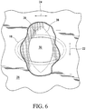
- the compression of the retractor sheath 18 by the walls of the incision 28 will cause the length dimension 22 of the retractor sheath 18 to decrease and the width dimension 24 of the retractor sheath 18 to increase (see Figure 6 ).
- the dimensions of the retractor sheath 18 and the rigidity of the retractor sheath 18 can then be optimized so that little "d” and big "D" of the incision 28 will converge to equal each other and, therefore, form an incision opening with a circular shape.
- the incision length establishes the perimeter of the incision opening 36. With a known perimeter, the relationship for little “d” and big “D” can also be established. The limits for little “d” and big “D” will, therefore, depend on the typical incision length sizes. From Eqn. 3, the maximum value for little “d” (“dmax”) and the minimum value for big “D” (“Dmin”) can be calculated from the incision length. The following table lists calculated values for "dmax” and "Dmin” based on some typical incision lengths.
- Incision Length (cm) Incision Perimeter (cm) "Dmin” or “dmax” (cm) 5.0 10.0 3.2 5.5 11.0 3.5 6.0 12.0 3.8 6.5 13.0 4.1 7.0 14.0 4.5 7.5 15.0 4.8 8.0 16.0 5.1 8.5 17.0 5.4 9.0 18.0 5.7
- the range of little “d” can be between zero and “dmax” while the range of big “D” can be between “Dmin” and the incision length.
- the initial starting dimensions for the elliptical retractor 10 will depend on the target value for the incision perimeter (retractor 10 perimeter) and a starting value for either little "d” or big "D.” An example of designing an elliptical retractor 10 device is shown below.
- a possible retractor design could target the nominal incision length, which in the above table is 7.0 cm and results in a perimeter of 14.0 cm.
- Another design factor that needs to be considered is the value for big "D” such that placement of the retractor 10 in the incision opening is not hindered.
- a possible value for big "D” could be 5.0 cm, which represents the smallest incision length in the above table.
- Eqn. 2 the little "d” can be calculated.
- the retractor 10 and the remainder of a seal assembly 12 are secured to the abdominal wall 26 of an individual patient by first creating an incision 28 and positioning the retractor 10 above the incision 28. Thereafter, the lower retractor ring 16 of the retractor 10 is inserted into the body cavity 30 with the abdominal wall 26 between the upper retractor ring 14 and the lower retractor ring 16. The tension between the upper retractor ring 14 and the lower retractor ring 16 as they extend between the external and internal portion of the incision 28 creates substantial rigidity in the central body portion 44 of the retractor sheath 18 allowing for stretching of the incision 28 in a manner optimizing retraction thereof in a manner discussed herein in greater detail.
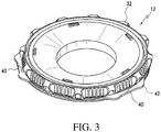
- a seal cap 32 of the seal assembly 12 is then connected to the upper retractor ring 14 of the retractor 10.
- the upper retractor ring 14 is provided with a series of resilient latch members 38 which are shaped and dimensioned to engage recesses 40 in the sidewall 42 of the seal cap 32 for securing the retractor 18 to the seal cap 32.
- various mechanisms are available for securing a retractor to a seal cap. Examples of such coupling structures are disclosed in commonly owned U.S. Patent 2008249371 , entitled “HAND ASSISTED LAPAROSCOPIC SEAL ASSEMBLY WITH DETACHABLE ATTACHMENT RING", filed April 4, 2007.
- the surgical site is prepared in accordance with conventional standard hospital procedures, making sure the skin is clean and dry. Thereafter, a template is placed over the incision site and an incision line is marked upon the template using a sterile skin marker.
- the glove size dictates the size of the incision 28. For example, if the surgeon's glove size is 7, a 6.5 to 7.0 cm incision 28 is usually appropriate. Thereafter, an incision 28 is made along the marked incision line. The incision size is thereafter verified by inserting the surgeon's hand into the abdomen prior to installing the retractor 10 and the remainder of the seal assembly 12.
- the incision is extended on each end as required to maintain the central position of the incision relative to the placement of the present seal assembly 12. Thereafter, the lower retractor ring 16 of the retractor 10 is inserted through the incision 28. Using one's fingers, the lower retractor ring 16 of the retractor 10 is seated evenly under the peritoneum and the area is swept to ensure the retractor 10 is not lying between tissue layers. In view of the shape of the retractor sheath 18, and, in particular, the central body portion 44, minimal resistance to insertion is achieved by orienting the retractor 10 so the length dimension 22 is oriented substantially parallel to the length of the incision 28.
- the upper retractor ring 14 and the lower retractor ring 16 are positioned on opposite sides of the abdominal wall 26.
- the tension between the upper retractor ring 14 and the lower retractor ring 16 as they extend between the external and internal portion of the incision 28 creates substantial rigidity in the retractor sheath 18 allowing for stretching of the incision 28 in a manner optimizing retraction thereof in a manner discussed herein in greater detail.
- the retractor 10 is then rotated 90 degrees so the length dimension 22 of the central body portion 44 of the retractor sheath 18 is oriented perpendicular to the length of the incision 28.
- This orientation orients the central body portion 44 of the retractor sheath 18 such that it expands the little "d" dimension of the incision 28 so as to expand the wound to its maximum shape and the stability of the retractor 10 is maximized to prevent or reduce spinning of the retractor 10 within the incision 28 (see Figure 6 ).
- seal cap 32 is attached to the upper retractor ring 14 of the retractor 10 and adjustments are made to ensure the seal assembly 12 is secured with the patient's abdomen maintaining pneumo.
- the concepts underlying the present retractor may be applied to fixed length or adjustable length retractors. In either case, the retractor must fit the abdominal wall thickness to maintain stability and pneumo.
Description
- The invention relates to a wound retractor. More particularly, the invention relates to an elliptically shaped wound retractor for use with laparoscopic surgery and in conjunction with a seal employed in hand assisted laparoscopic surgery.
- During laparoscopic procedures it is often necessary to inflate the abdominal cavity in order to increase the volume of the working space. This is accomplished through the utilization of insufflation gas which must be maintained at a pressure sufficient to elevate the abdominal wall. The pressure supplied by the insufflation gas is generally controlled by positioning a seal assembly at the access point for the laparoscopic surgery. The seal is connected to the wound in a manner substantially sealing off the abdominal cavity through the utilization of a retractor. The retractor extends between the seal assembly and the interior wall along the tissue.
- In addition to sealing off the abdominal cavity, the retractor offers the tissue adjacent the wound protection from abrasion, bacteria or other contaminants. It also allows organs to be removed while minimizing the risk of damage to the organs.
-
AU977266A US2004054353A1 relates to a surgical access device for access through an incision in a body wall, the device comprising first and second retention members sized and configured to surround the incision in proximity to the respective outer surface and the inner surface of the body wall, and a membrane extending between the first and second retention members, the membrane forming a throat adapted for disposition through the incision, and the throat of the membrane having characteristics for forming an instrument seal in the presence of an instrument and a zero seal in the absence of an instrument.US6589211B1 relates to a surgical access device in the form of a sealing ring that includes a first extended region and a second extended region which are integrally connected to a ring wall and extend outwardly therefrom.WO0108581A2 EP1312318A1 andUS6440063B1 both relate to a device for retracting an incision including: a flexible, tubular skirt having an upper end, a lower end, and a channel therebetween; a ring connected to the lower end of the skirt for maintaining the lower end in an open configuration and defining an exit opening to the channel; and an inflatable collar connected to the skirt and surrounding the upper end.WO0126559A1 - Many retractor devices that are currently used in surgical procedures use a flexible cylindrical sleeve (circular cross-section) design to perform retraction. When placing into the incision opening, the cylindrical sleeve can be squeezed to fit into the opening. Once placed in the incision opening, the rigidity of the cylindrical sleeve determines how much the incision stays open against the compressive force of the incision walls. However, unless the sleeve is extremely rigid so as to maintain its circular cross-section, it will form an elliptical shape with corresponding values for little "d" (that is, the width of incision opening perpendicular to incision direction) and big "D" (that is, the width of incision opening parallel to incision direction) based on the rigidity of the sleeve. In order to achieve a circular shape, the rigidity of the sleeve can only be increased so much until it deters the placement of the sleeve into the incision opening.
- Given the usefulness of such retractors, it is an ongoing endeavor to improve upon currently existing retractors.
- Claim 1 defines the invention and the dependent claims disclose the preferred embodiments. It is, therefore, an object of the present invention to provide a retractor for use in laparoscopic procedures. The retractor of the present invention is defined in the accompanying independent claim. The retractor includes an upper retractor ring, a lower retractor ring, and a retractor sheath extending between the upper retractor ring and the lower retractor ring to form a tubular passageway through which instruments or a medical practitioner's hands may pass during a medical procedure. The retractor sheath defines an elliptical passageway extending between the lower retractor ring and the upper retractor ring.
- It is also an object of the present invention to provide a retractor wherein the upper retractor ring is rigid.
- It is also another object of the present invention to provide a retractor wherein the upper retractor ring is circular in shape.
- It is another object of the present invention to provide a retractor wherein the lower retractor ring is flexible.
- It is a further object of the present invention to provide a retractor wherein the lower retractor ring is elliptical in shape.
- It is still a further object of the present invention to provide a retractor wherein the lower retractor ring is circular in shape.
- It is a further object of the present invention to provide a seal assembly with a retractor as described above.
- Lastly, it is an object of the present invention to provide a retractor sheath having an elliptical passageway wherein the perimeter (P) of the elliptical passageway is expressed as a function of its small diameter (d) and its larger diameter (D) and the following formula:

- Other objects and advantages of the present invention will become apparent from the following detailed description when viewed in conjunction with the accompanying drawings, which set forth certain embodiments of the invention.
-
-
Figure 1 is a perspective view of a laparoscopic seal assembly in accordance with the present invention prior to insertion within an incision. -
Figure 2 is a top view of the laparoscopic seal assembly shown inFigure 1 . -
Figure 3 is a perspective view of the seal cap in accordance with the present invention. -
Figure 4 is a perspective view of the retractor in accordance with the present invention. -
Figure 5 is top view of retractor shown inFigure 4 . -
Figure 6 is a top view of the laparoscopic seal assembly inserted and twisted within an incision. -
Figures 7, 8 and 9 are schematics showing the potential shapes for an incision. - The detailed embodiments of the present invention are disclosed herein. It should be understood, however, that the disclosed embodiments are merely exemplary of the invention, which may be embodied in various forms within the scope of the claims. Therefore, the details disclosed herein are not to be interpreted as limiting, but merely as a basis for teaching one skilled in the art how to make and/or use the invention.
- In accordance with the present invention, and with reference to
Figures 1 to 6 , aretractor 10 in accordance with the present invention is disclosed. In accordance with the present disclosure, theretractor 10 is shown secured to aseal assembly 12 for utilization in hand assisted laparoscopic procedures. Theseal assembly 12 may be similar to those disclosed in commonly ownedU.S. Patent US2008221483 , entitled "HAND ASSISTED LAPAROSCOPIC SEAL ASSEMBLY WITH A RATCHET MECHANISM", filed March 6, 2007. Although thepresent retractor 10 is disclosed for use in conjunction with aseal assembly 12, those skilled in the art will appreciate theretractor 10 may be used on it own where greater access to thebody cavity 30 is desired. - Briefly, the
retractor 10 includes anupper retractor ring 14, alower retractor ring 16, and aretractor sheath 18 extending between theupper retractor ring 14 and thelower retractor ring 16 to form atubular passageway 20 through which instruments or a medical practitioner's hands may pass during a medical procedure. Theretractor sheath 18 defines anelliptical passageway 20 extending between thelower retractor ring 14 and theupper retractor ring 16. In accordance with a preferred embodiment of the present invention, theretractor 10 is a fixed length retractor, although those skilled in the art will appreciate the concepts of the present invention may be applied to "roll-up" retractors without departing from the scope of the present invention. - More particularly, the
retractor 10 includes anupper retractor ring 14 and alower retractor ring 16. Theupper retractor ring 14 is a rigid ring member preferably composed of polycarbonate and thelower retractor ring 16 is a flexible ring member preferably composed of polyurethane. While polycarbonate and polyurethane are respectively disclosed as preferred materials, those skilled in the art will appreciate other materials may be employed without departing from the scope of the present invention. For example, it is contemplated ABS (Acrylonitrile-Butadiene-Styrene), carbon-filled nylon and/or a high performance thermoplastic, such as VECTRA (a liquid crystal polyester) may be employed in the manufacture of the upper retractor ring, while polyethylene and/or thermoplastic polyurethane elastomers, such as Pellethane may be employed in the manufacture of the lower retractor ring. - The upper and
lower retractor rings elastic retractor sheath 18 to form atubular passageway 20 through which instruments or a medical practitioner's hands may pass during a medical procedure. In accordance with a preferred embodiment, theretractor sheath 18 is composed of polyurethane. While polyurethane is disclosed as a preferred material, those skilled in the art will appreciate other materials such as silicon and polyethylene may be employed without departing from the scope of the present invention. As will be discussed below in greater detail, theretractor sheath 18 is formed with acentral body portion 44 having a substantially elliptical cross section when viewed within a plane that is substantially perpendicular to the longitudinal axis as theretractor 10 extends from theupper retractor ring 14 to thelower retractor ring 16. - In accordance with the preferred invention, the
upper retractor ring 14 is formed in the shape of a circle, so as to maximize the space for which instruments or a medical practitioner's hands may pass. More particularly, and in accordance with a preferred embodiment of the present invention, theupper retractor ring 14 has a circular cross sectional shape when viewed within a plane that is substantially perpendicular to the longitudinal axis as theretractor 10 extends from theupper retractor ring 14 to thelower retractor ring 16. - As stated previously, the
lower retractor ring 16 is flexible. In accordance with a preferred embodiment it is constructed with a circular cross sectional configuration, although it is contemplated it may be constructed with an elliptical cross sectional configuration. More particularly, thelower retractor ring 16 has an elliptical or circular cross sectional shape when viewed within a plane that is substantially perpendicular to the longitudinal axis as theretractor 10 extends from theupper retractor ring 14 to thelower retractor ring 16. However, and as those skilled in the art will certainly appreciate based upon the following disclosure, the shape of the lower retractor ring may be varied to suit specific applications without departing from the scope of the present invention. - In order to enhance conformance of the
retractor sheath 18 to the circularupper retractor ring 14 and thelower retractor ring 16, theretractor sheath 18 is shaped so as to conform to the shapes of the upper and lower retractor rings 14, 16 in the area adjacent the respective upper and lower retractor rings 14, 16. As such, theretractor sheath 18 is circular in shape adjacent theupper retractor ring 14 and either circular or elliptical adjacent thelower retractor ring 16. With this in mind, theretractor sheath 18 includes anupper transition section 46 adjacent theupper retractor ring 14 that extends from theupper retractor ring 14, which has a substantially circular cross sectional shape, to thecentral body portion 44, which has a substantially elliptical cross sectional shape. Similarly, theretractor sheath 18 includes alower transition section 48 adjacent thelower retractor ring 16 that extends from theupper retractor ring 16, which has a substantially circular or elliptical cross sectional shape, to thecentral body portion 44, which has a substantially elliptical cross sectional shape. - As mentioned above, the
retractor sheath 18 includes acentral body portion 44 shaped so as to form a tube having an elliptical cross sectional shape when viewed within a plane that is substantially perpendicular to the longitudinal axis as theretractor 10 extends from theupper retractor ring 14 to thelower retractor ring 16. More particularly, the ellipticalcentral body portion 44 of theretractor sheath 18 includes alength dimension 22 and awidth dimension 24, wherein thelength dimension 22 is greater than thewidth dimension 24. As a result, theretractor sheath 18 changes in its cross-sectional shape as it extends from theupper retractor ring 14, which is circular in shape, to thecentral body portion 44 of theretractor sheath 18, which is elliptical in shape, and then to thelower retractor ring 16, which is generally elliptical or circular in shape. The changes in shape are achieved through the inclusion of theupper transition section 46 and thelower transition section 48. - As is discussed below in greater detail, when the upper and lower retractor rings 14, 16 are positioned on opposite sides of the
abdominal wall 26, theretractor sheath 18 is tensioned holding its elliptical shape along thecentral body portion 44 against the pressure being applied by the wall of theincision 28. It is the rigidity of the elliptically-shapedcentral body portion 44 of theretractor sheath 18 which helps to deform theincision 28 to its ideal shape for access and utilization in conjunction with aseal assembly 12 as discussed above. - More particularly, as a result of the elliptically shaped
central body portion 44 of theretractor sheath 18, when thelower retractor ring 16 is positioned within theincision 28 with thelength dimension 22 of thecentral body portion 44 of theretractor sheath 18 at 90 degrees relative to the long dimension of theincision 28, and theincision 28 is expanded to its maximum shape, the stability of theretractor 10 within the wound is maximized to prevent and/or reduce spinning of theretractor 10 within theincision 28. - In accordance with a preferred embodiment, and with reference to
Figures 7, 8 and 9 , the oval of thecentral body portion 44 of theretractor sheath 18 is constructed with the following in mind:
where, - L = initial incision length
- d = width of incision opening perpendicular to incision direction
- D = width of incision opening parallel to incision direction
- P = perimeter of incision opening
- Retraction performance is generally defined as the shape of the incision opening 36 that the
retractor 10 can form. When the incision opening 36 is retracted, it generally forms the shape of an ellipse. The ellipse is defined by two width dimensions (or a width and length dimension depending upon one's perspective), that is, little "d" (which is dimension of the incision perpendicular to the incision direction) and big "D" (which is the dimension of the incision parallel to the incision direction). The perimeter of an ellipse can be expressed as a function of "d" and "D".
- The
initial incision 28 length determines the size of the ellipse that can be defined by theincision 28 since it establishes the perimeter of the ellipse. The perimeter of the ellipse is substantially equal to twice the initial incision length. The incision length can, therefore, be used to establish the relationship between little "d" and big "D".
- When little "d" reaches its maximum value ("dmax"), it equals big "D" at its minimum value ("Dmin"), and the equation for the perimeter of the ellipse becomes the equation for the perimeter (circumference) of a circle.

- In accordance with the present invention, the performance of the
retractor 10 is rated based upon the size of the incision opening.Retractor 10 performance is rated best when the shape of the incision opening approaches the shape of a circle; that is when "d" is approximately the same as "D". With this in mind, thepresent retractor 10 is designed to create a retracted incision opening whose dimensions little "d" and big "D" will converge to equal each other (maximum little "d" equals minimum big "D"). - The
present retractor 10 achieves the goal of stretching theincision 28 into a substantially circular configuration by providing aretractor 10 exhibiting an elliptical cross-section designed to stretch theincision 28 into a shape approaching a circle while similarly deforming to approach the shape of a circle when compressed under the pressure of incision walls. The elliptical cross-section of theretractor sheath 18 therefore has length and width dimensions which are substantially different. When placed into the incision opening 36 with thelength dimension 22 of theretractor sheath 18 oriented perpendicular to the incision direction and thewidth dimension 24 of theretractor sheath 18 oriented along the incision direction, the compression of theretractor sheath 18 by the walls of theincision 28 will cause thelength dimension 22 of theretractor sheath 18 to decrease and thewidth dimension 24 of theretractor sheath 18 to increase (seeFigure 6 ). As those skilled in the art will certainly appreciate, the dimensions of theretractor sheath 18 and the rigidity of theretractor sheath 18 can then be optimized so that little "d" and big "D" of theincision 28 will converge to equal each other and, therefore, form an incision opening with a circular shape. - As defined previously, the incision length establishes the perimeter of the
incision opening 36. With a known perimeter, the relationship for little "d" and big "D" can also be established. The limits for little "d" and big "D" will, therefore, depend on the typical incision length sizes. From Eqn. 3, the maximum value for little "d" ("dmax") and the minimum value for big "D" ("Dmin") can be calculated from the incision length. The following table lists calculated values for "dmax" and "Dmin" based on some typical incision lengths.Incision Length (cm) Incision Perimeter (cm) "Dmin" or "dmax" (cm) 5.0 10.0 3.2 5.5 11.0 3.5 6.0 12.0 3.8 6.5 13.0 4.1 7.0 14.0 4.5 7.5 15.0 4.8 8.0 16.0 5.1 8.5 17.0 5.4 9.0 18.0 5.7 - The range of little "d" can be between zero and "dmax" while the range of big "D" can be between "Dmin" and the incision length. The initial starting dimensions for the
elliptical retractor 10 will depend on the target value for the incision perimeter (retractor 10 perimeter) and a starting value for either little "d" or big "D." An example of designing anelliptical retractor 10 device is shown below. - In order to accommodate a varying range of incision lengths, a possible retractor design could target the nominal incision length, which in the above table is 7.0 cm and results in a perimeter of 14.0 cm. Another design factor that needs to be considered is the value for big "D" such that placement of the
retractor 10 in the incision opening is not hindered. To help facilitate placement of theretractor 10 for small incision sizes, a possible value for big "D" could be 5.0 cm, which represents the smallest incision length in the above table. Using Eqn. 2, the little "d" can be calculated. The following calculations shows an example of an elliptical retractor design based on a retractor perimeter of 14.0 cm and a big "D" of 5.0 cm.

- In practice, the
retractor 10 and the remainder of aseal assembly 12 are secured to theabdominal wall 26 of an individual patient by first creating anincision 28 and positioning theretractor 10 above theincision 28. Thereafter, thelower retractor ring 16 of theretractor 10 is inserted into thebody cavity 30 with theabdominal wall 26 between theupper retractor ring 14 and thelower retractor ring 16. The tension between theupper retractor ring 14 and thelower retractor ring 16 as they extend between the external and internal portion of theincision 28 creates substantial rigidity in thecentral body portion 44 of theretractor sheath 18 allowing for stretching of theincision 28 in a manner optimizing retraction thereof in a manner discussed herein in greater detail. Aseal cap 32 of theseal assembly 12 is then connected to theupper retractor ring 14 of theretractor 10. In accordance with a preferred embodiment of the present invention, theupper retractor ring 14 is provided with a series ofresilient latch members 38 which are shaped and dimensioned to engagerecesses 40 in thesidewall 42 of theseal cap 32 for securing theretractor 18 to theseal cap 32. As those skilled in the art will certainly appreciate, various mechanisms are available for securing a retractor to a seal cap. Examples of such coupling structures are disclosed in commonly ownedU.S. Patent 2008249371 , entitled "HAND ASSISTED LAPAROSCOPIC SEAL ASSEMBLY WITH DETACHABLE ATTACHMENT RING", filed April 4, 2007. - More particularly, the surgical site is prepared in accordance with conventional standard hospital procedures, making sure the skin is clean and dry. Thereafter, a template is placed over the incision site and an incision line is marked upon the template using a sterile skin marker. As those skilled in the art will appreciate, the glove size dictates the size of the
incision 28. For example, if the surgeon's glove size is 7, a 6.5 to 7.0cm incision 28 is usually appropriate. Thereafter, anincision 28 is made along the marked incision line. The incision size is thereafter verified by inserting the surgeon's hand into the abdomen prior to installing theretractor 10 and the remainder of theseal assembly 12. If the incision is too small, the incision is extended on each end as required to maintain the central position of the incision relative to the placement of thepresent seal assembly 12. Thereafter, thelower retractor ring 16 of theretractor 10 is inserted through theincision 28. Using one's fingers, thelower retractor ring 16 of theretractor 10 is seated evenly under the peritoneum and the area is swept to ensure theretractor 10 is not lying between tissue layers. In view of the shape of theretractor sheath 18, and, in particular, thecentral body portion 44, minimal resistance to insertion is achieved by orienting theretractor 10 so thelength dimension 22 is oriented substantially parallel to the length of theincision 28. Theupper retractor ring 14 and thelower retractor ring 16 are positioned on opposite sides of theabdominal wall 26. The tension between theupper retractor ring 14 and thelower retractor ring 16 as they extend between the external and internal portion of theincision 28 creates substantial rigidity in theretractor sheath 18 allowing for stretching of theincision 28 in a manner optimizing retraction thereof in a manner discussed herein in greater detail. Theretractor 10 is then rotated 90 degrees so thelength dimension 22 of thecentral body portion 44 of theretractor sheath 18 is oriented perpendicular to the length of theincision 28. This orientation orients thecentral body portion 44 of theretractor sheath 18 such that it expands the little "d" dimension of theincision 28 so as to expand the wound to its maximum shape and the stability of theretractor 10 is maximized to prevent or reduce spinning of theretractor 10 within the incision 28 (seeFigure 6 ). - Thereafter, the
seal cap 32 is attached to theupper retractor ring 14 of theretractor 10 and adjustments are made to ensure theseal assembly 12 is secured with the patient's abdomen maintaining pneumo. - As those skilled in the art will certainly appreciate, the concepts underlying the present retractor may be applied to fixed length or adjustable length retractors. In either case, the retractor must fit the abdominal wall thickness to maintain stability and pneumo.
- While the preferred embodiments have been shown and described, it will be understood that there is no intent to limit the invention by such disclosure, but rather, is intended to cover all modifications and alternate constructions falling within the scope of the invention.
Claims (11)
- A retractor for use in laparoscopic procedures, comprising:an upper retractor ring (14);a lower retractor ring (16); anda retractor sheath (18) connecting the upper retractor ring (14) and the lower retractor ring (16) to form a tubular passageway through which instruments or a medical practitioner's hands may pass during a medical procedure;wherein the retractor sheath (18) includes a central body portion (44);
characterised in that:said central body portion (44) has an elliptical cross section when viewed within a plane that is perpendicular to a longitudinal axis as the retractor (10) extends from the upper retractor ring (14) to the lower retractor ring (16) so as to define an elliptical passageway (20),said elliptical passageway (20) extends between an upper transition section (46) and a lower transition section (48) of the retractor sheath (18), said upper transition section (46) extending from the upper retractor ring (14) to the elliptical passageway (20), said lower transition section (48) extending from the lower retractor ring (16) to the elliptical passageway (20), such that the retractor sheath (18) conforms to the shape of the upper retractor ring (14) in an area adjacent the upper retractor ring (14) and conforms to the shape of the lower retractor ring (16) in an area adjacent the lower retractor ring (16). - The retractor according to claim 1, wherein the upper retractor ring is rigid.
- The retractor according to claim 2, wherein the upper retractor ring is circular in shape.
- The retractor according to claim 1, wherein the upper retractor ring is circular in shape.
- The retractor according to claim 1, wherein the lower retractor ring is flexible.
- The retractor according to claim 1, wherein the lower retractor ring is elliptical in shape.
- The retractor according to claim 1, wherein the lower retractor ring is circular in shape.
- The retractor according to claim 5, wherein the lower retractor ring is elliptical in shape.
- The retractor according to claim 5, wherein the lower retractor ring is circular in shape.
- The retractor according to claim 1, wherein the perimeter (P) of the elliptical passageway is expressed as a function of its small diameter (d) and its larger diameter (D) by the following formula:

- A seal assembly with retractor for use in laparoscopic procedures, comprising:a seal cap (32); anda retractor according to any preceding claim.
Applications Claiming Priority (2)
| Application Number | Priority Date | Filing Date | Title |
|---|---|---|---|
| US11/902,662 US8308755B2 (en) | 2007-09-24 | 2007-09-24 | Elliptical retractor |
| PCT/US2008/076938 WO2009042505A1 (en) | 2007-09-24 | 2008-09-19 | Elliptical retractor |
Publications (2)
| Publication Number | Publication Date |
|---|---|
| EP2197358A1 EP2197358A1 (en) | 2010-06-23 |
| EP2197358B1 true EP2197358B1 (en) | 2019-01-09 |
Family
ID=40032413
Family Applications (1)
| Application Number | Title | Priority Date | Filing Date |
|---|---|---|---|
| EP08833002.2A Not-in-force EP2197358B1 (en) | 2007-09-24 | 2008-09-19 | Elliptical retractor |
Country Status (8)
| Country | Link |
|---|---|
| US (1) | US8308755B2 (en) |
| EP (1) | EP2197358B1 (en) |
| JP (1) | JP5583583B2 (en) |
| KR (1) | KR20100061842A (en) |
| CN (1) | CN101808585B (en) |
| AU (1) | AU2008304677B2 (en) |
| CA (1) | CA2700482A1 (en) |
| WO (1) | WO2009042505A1 (en) |
Families Citing this family (35)
| Publication number | Priority date | Publication date | Assignee | Title |
|---|---|---|---|---|
| US8142354B1 (en) | 2007-10-30 | 2012-03-27 | Ethicon Endo-Surgery, Inc. | Laminated surgical access port |
| US8273017B1 (en) | 2007-10-30 | 2012-09-25 | Ethicon Endo-Surgery, Inc. | Surgical access port with ring actuated latching mechanism |
| WO2010088548A1 (en) | 2009-01-29 | 2010-08-05 | Forsight Labs, Llc | Posterior segment drug delivery |
| US8623395B2 (en) | 2010-01-29 | 2014-01-07 | Forsight Vision4, Inc. | Implantable therapeutic device |
| US8460356B2 (en) | 2009-12-18 | 2013-06-11 | Scion Neurostim, Llc | Devices and methods for vestibular and/or cranial nerve stimulation |
| US8480683B2 (en) * | 2009-11-24 | 2013-07-09 | Covidien Lp | Foam introduction system including modified port geometry |
| RS61601B1 (en) | 2010-08-05 | 2021-04-29 | Forsight Vision4 Inc | Injector apparatus for drug delivery |
| US9492315B2 (en) | 2010-08-05 | 2016-11-15 | Forsight Vision4, Inc. | Implantable therapeutic device |
| US10617557B2 (en) | 2010-08-05 | 2020-04-14 | Forsight Vision4, Inc. | Combined drug delivery methods and apparatus |
| US8597180B2 (en) * | 2010-08-12 | 2013-12-03 | Covidien Lp | Expandable thoracic access port |
| EP2621348B1 (en) | 2010-10-01 | 2019-06-12 | Applied Medical Resources Corporation | Natural orifice surgery system |
| US20140031769A1 (en) | 2010-11-19 | 2014-01-30 | Forsight Vision4, Inc. | Therapeutic agent formulations for implanted devices |
| CN102743199A (en) * | 2011-04-20 | 2012-10-24 | 北京航天卡迪技术开发研究所 | Cut protection retractor |
| EP2726016B1 (en) | 2011-06-28 | 2023-07-19 | ForSight Vision4, Inc. | An apparatus for collecting a sample of fluid from a reservoir chamber of a therapeutic device for the eye |
| EP2739252A4 (en) | 2011-08-05 | 2015-08-12 | Forsight Vision4 Inc | Small molecule delivery with implantable therapeutic device |
| RS61758B1 (en) | 2011-09-16 | 2021-05-31 | Forsight Vision4 Inc | Fluid exchange apparatus |
| CN102429689A (en) * | 2011-10-08 | 2012-05-02 | 金黑鹰 | Disposable multi-angle mono-hole converter for laparoscope |
| KR101301914B1 (en) * | 2011-11-09 | 2013-08-30 | (주)유원메디텍 | single port for surgical operation |
| US10010448B2 (en) | 2012-02-03 | 2018-07-03 | Forsight Vision4, Inc. | Insertion and removal methods and apparatus for therapeutic devices |
| EP2968113B8 (en) | 2013-03-14 | 2020-10-28 | Forsight Vision4, Inc. | Systems for sustained intraocular delivery of low solubility compounds from a port delivery system implant |
| JP6559648B2 (en) | 2013-03-15 | 2019-08-14 | アプライド メディカル リソーシーズ コーポレイション | Trocar surgical seal |
| CA2907681C (en) | 2013-03-28 | 2022-11-22 | Forsight Vision4, Inc. | Ophthalmic implant for delivering therapeutic substances |
| RU2695563C2 (en) | 2014-07-15 | 2019-07-24 | Форсайт Вижн4, Инк. | Method and device for eye implant delivery |
| WO2016022750A1 (en) | 2014-08-08 | 2016-02-11 | Forsight Vision4, Inc. | Stable and soluble formulations of receptor tyrosine kinase inhibitors, and methods of preparation thereof |
| ES2930777T3 (en) * | 2014-08-15 | 2022-12-21 | Applied Med Resources | Natural orifice surgery system |
| JP7037360B2 (en) | 2014-11-10 | 2022-03-16 | フォーサイト・ビジョン フォー・インコーポレーテッド | Expandable drug delivery device |
| KR101592975B1 (en) * | 2015-08-19 | 2016-02-12 | 위캔메디케어 주식회사 | Surgical retractor |
| KR101812059B1 (en) * | 2015-09-16 | 2017-12-27 | 위캔메디케어 주식회사 | Surgical retractor |
| CN105380688A (en) * | 2015-10-26 | 2016-03-09 | 北京迈迪顶峰医疗科技有限公司 | Retractor |
| USD788300S1 (en) * | 2015-10-27 | 2017-05-30 | Orthogrid Systems, Inc. | Grid positioning device |
| WO2017087902A1 (en) | 2015-11-20 | 2017-05-26 | Forsight Vision4, Inc. | Porous structures for extended release drug delivery devices |
| MX2018012021A (en) | 2016-04-05 | 2019-01-24 | Forsight Vision4 Inc | Implantable ocular drug delivery devices. |
| BR112020010053A2 (en) | 2017-11-21 | 2020-11-03 | Forsight Vision4, Inc. | fluid change device for expandable door release system and methods of using it |
| KR20230055756A (en) * | 2021-10-19 | 2023-04-26 | 드림팩 주식회사 | Surgical retractor for preventing gas leakage in abdominal cavity |
| KR20230117838A (en) | 2022-02-03 | 2023-08-10 | 인제대학교 산학협력단 | Surgical wound protection clip unit |
Citations (3)
| Publication number | Priority date | Publication date | Assignee | Title |
|---|---|---|---|---|
| WO2001026559A1 (en) * | 1999-10-14 | 2001-04-19 | Atropos Limited | A retractor |
| US6440063B1 (en) * | 1997-04-30 | 2002-08-27 | University Of Massachusetts | Surgical access port and laparoscopic surgical method |
| EP1312318A1 (en) * | 1997-04-30 | 2003-05-21 | University of Massachusetts | Surgical access port |
Family Cites Families (17)
| Publication number | Priority date | Publication date | Assignee | Title |
|---|---|---|---|---|
| AU977266A (en) | 1966-08-17 | 1968-02-22 | Johnson And Johnson | Wound edge protector |
| JPH0813304B2 (en) * | 1991-05-10 | 1996-02-14 | 株式会社ニッショー | Incision opening device |
| US5460170A (en) * | 1994-08-23 | 1995-10-24 | Hammerslag; Julius G. | Adjustable surgical retractor |
| US6589211B1 (en) * | 1995-04-28 | 2003-07-08 | Macleod Cathel | Modified trocar and methods of use |
| US7559893B2 (en) * | 1998-12-01 | 2009-07-14 | Atropos Limited | Wound retractor device |
| JP3062106U (en) * | 1999-03-11 | 1999-09-28 | 株式会社八光電機製作所 | Wound edge protection device with retracting site holding function |
| IE990795A1 (en) | 1999-07-30 | 2001-03-07 | Gaya Ltd | Hand Access Port Device |
| US7540839B2 (en) * | 1999-10-14 | 2009-06-02 | Atropos Limited | Wound retractor |
| US7052454B2 (en) | 2001-10-20 | 2006-05-30 | Applied Medical Resources Corporation | Sealed surgical access device |
| US6723044B2 (en) * | 2002-03-14 | 2004-04-20 | Apple Medical Corporation | Abdominal retractor |
| EP2340792B1 (en) * | 2002-06-05 | 2012-05-09 | Applied Medical Resources Corporation | Wound retractor |
| CA2522766C (en) * | 2003-04-25 | 2011-07-05 | Tyco Healthcare Group Lp | Surgical hand access apparatus |
| US20060161050A1 (en) * | 2003-10-15 | 2006-07-20 | John Butler | A surgical sealing device |
| US8857440B2 (en) * | 2004-06-22 | 2014-10-14 | DePuy Synthes Products, LLC | Devices and methods for protecting tissue at a surgical site |
| US20060229636A1 (en) * | 2005-03-04 | 2006-10-12 | Woodburn William N Sr | Expandable access device with mobility member |
| US7766824B2 (en) * | 2005-03-31 | 2010-08-03 | Tyco Healthcare Group Lp | Surgical hand access apparatus |
| JP5132565B2 (en) * | 2005-10-14 | 2013-01-30 | アプライド メディカル リソーシーズ コーポレイション | Method for manufacturing hand access instrument for laparoscopy |
-
2007
- 2007-09-24 US US11/902,662 patent/US8308755B2/en active Active
-
2008
- 2008-09-19 AU AU2008304677A patent/AU2008304677B2/en not_active Ceased
- 2008-09-19 EP EP08833002.2A patent/EP2197358B1/en not_active Not-in-force
- 2008-09-19 CN CN2008801084261A patent/CN101808585B/en not_active Expired - Fee Related
- 2008-09-19 WO PCT/US2008/076938 patent/WO2009042505A1/en active Application Filing
- 2008-09-19 CA CA2700482A patent/CA2700482A1/en not_active Abandoned
- 2008-09-19 JP JP2010525987A patent/JP5583583B2/en active Active
- 2008-09-19 KR KR1020107008696A patent/KR20100061842A/en not_active Application Discontinuation
Patent Citations (3)
| Publication number | Priority date | Publication date | Assignee | Title |
|---|---|---|---|---|
| US6440063B1 (en) * | 1997-04-30 | 2002-08-27 | University Of Massachusetts | Surgical access port and laparoscopic surgical method |
| EP1312318A1 (en) * | 1997-04-30 | 2003-05-21 | University of Massachusetts | Surgical access port |
| WO2001026559A1 (en) * | 1999-10-14 | 2001-04-19 | Atropos Limited | A retractor |
Also Published As
| Publication number | Publication date |
|---|---|
| JP2010540034A (en) | 2010-12-24 |
| AU2008304677B2 (en) | 2013-05-23 |
| CN101808585A (en) | 2010-08-18 |
| CN101808585B (en) | 2013-06-12 |
| CA2700482A1 (en) | 2009-04-02 |
| WO2009042505A1 (en) | 2009-04-02 |
| JP5583583B2 (en) | 2014-09-03 |
| AU2008304677A1 (en) | 2009-04-02 |
| EP2197358A1 (en) | 2010-06-23 |
| KR20100061842A (en) | 2010-06-09 |
| US20090082631A1 (en) | 2009-03-26 |
| US8308755B2 (en) | 2012-11-13 |
Similar Documents
| Publication | Publication Date | Title |
|---|---|---|
| EP2197358B1 (en) | Elliptical retractor | |
| US20060149137A1 (en) | Easily placeable and removable wound retractor | |
| US9668721B2 (en) | Wound retractor including rigid ring | |
| EP2275040B1 (en) | Wound retraction apparatus | |
| US8231527B2 (en) | Roll-up wound protector with asymmetric ring | |
| JP4181306B2 (en) | Wound retractor device | |
| EP1407715B1 (en) | Medical treating instrument | |
| JP4528956B2 (en) | Laparoscopy sealed access device | |
| US6814078B2 (en) | Surgical retractor and liner | |
| US20080021360A1 (en) | Roll-up wound protector | |
| US20080021362A1 (en) | Roll-up wound protector with tricuspidate ring | |
| JP4623067B2 (en) | Medical treatment tool | |
| JP4082952B2 (en) | Medical treatment tool | |
| US20220395293A1 (en) | Transvaginal access devices and methods of use | |
| EP4297656A1 (en) | Circumferential retractor system | |
| AU2009203014A1 (en) | Surgical access port with cinching attachment mechanism |
Legal Events
| Date | Code | Title | Description |
|---|---|---|---|
| PUAI | Public reference made under article 153(3) epc to a published international application that has entered the european phase |
Free format text: ORIGINAL CODE: 0009012 |
|
| 17P | Request for examination filed |
Effective date: 20100423 |
|
| AK | Designated contracting states |
Kind code of ref document: A1 Designated state(s): AT BE BG CH CY CZ DE DK EE ES FI FR GB GR HR HU IE IS IT LI LT LU LV MC MT NL NO PL PT RO SE SI SK TR |
|
| AX | Request for extension of the european patent |
Extension state: AL BA MK RS |
|
| DAX | Request for extension of the european patent (deleted) | ||
| STAA | Information on the status of an ep patent application or granted ep patent |
Free format text: STATUS: EXAMINATION IS IN PROGRESS |
|
| 17Q | First examination report despatched |
Effective date: 20161110 |
|
| GRAP | Despatch of communication of intention to grant a patent |
Free format text: ORIGINAL CODE: EPIDOSNIGR1 |
|
| STAA | Information on the status of an ep patent application or granted ep patent |
Free format text: STATUS: GRANT OF PATENT IS INTENDED |
|
| INTG | Intention to grant announced |
Effective date: 20180720 |
|
| GRAS | Grant fee paid |
Free format text: ORIGINAL CODE: EPIDOSNIGR3 |
|
| GRAA | (expected) grant |
Free format text: ORIGINAL CODE: 0009210 |
|
| STAA | Information on the status of an ep patent application or granted ep patent |
Free format text: STATUS: THE PATENT HAS BEEN GRANTED |
|
| RAP1 | Party data changed (applicant data changed or rights of an application transferred) |
Owner name: ETHICON LLC |
|
| AK | Designated contracting states |
Kind code of ref document: B1 Designated state(s): AT BE BG CH CY CZ DE DK EE ES FI FR GB GR HR HU IE IS IT LI LT LU LV MC MT NL NO PL PT RO SE SI SK TR |
|
| REG | Reference to a national code |
Ref country code: GB Ref legal event code: FG4D |
|
| REG | Reference to a national code |
Ref country code: CH Ref legal event code: EP Ref country code: AT Ref legal event code: REF Ref document number: 1086335 Country of ref document: AT Kind code of ref document: T Effective date: 20190115 |
|
| REG | Reference to a national code |
Ref country code: IE Ref legal event code: FG4D |
|
| REG | Reference to a national code |
Ref country code: DE Ref legal event code: R096 Ref document number: 602008058711 Country of ref document: DE |
|
| REG | Reference to a national code |
Ref country code: NL Ref legal event code: MP Effective date: 20190109 |
|
| REG | Reference to a national code |
Ref country code: LT Ref legal event code: MG4D |
|
| PG25 | Lapsed in a contracting state [announced via postgrant information from national office to epo] |
Ref country code: NL Free format text: LAPSE BECAUSE OF FAILURE TO SUBMIT A TRANSLATION OF THE DESCRIPTION OR TO PAY THE FEE WITHIN THE PRESCRIBED TIME-LIMIT Effective date: 20190109 |
|
| REG | Reference to a national code |
Ref country code: AT Ref legal event code: MK05 Ref document number: 1086335 Country of ref document: AT Kind code of ref document: T Effective date: 20190109 |
|
| PG25 | Lapsed in a contracting state [announced via postgrant information from national office to epo] |
Ref country code: PT Free format text: LAPSE BECAUSE OF FAILURE TO SUBMIT A TRANSLATION OF THE DESCRIPTION OR TO PAY THE FEE WITHIN THE PRESCRIBED TIME-LIMIT Effective date: 20190509 Ref country code: ES Free format text: LAPSE BECAUSE OF FAILURE TO SUBMIT A TRANSLATION OF THE DESCRIPTION OR TO PAY THE FEE WITHIN THE PRESCRIBED TIME-LIMIT Effective date: 20190109 Ref country code: SE Free format text: LAPSE BECAUSE OF FAILURE TO SUBMIT A TRANSLATION OF THE DESCRIPTION OR TO PAY THE FEE WITHIN THE PRESCRIBED TIME-LIMIT Effective date: 20190109 Ref country code: LT Free format text: LAPSE BECAUSE OF FAILURE TO SUBMIT A TRANSLATION OF THE DESCRIPTION OR TO PAY THE FEE WITHIN THE PRESCRIBED TIME-LIMIT Effective date: 20190109 Ref country code: PL Free format text: LAPSE BECAUSE OF FAILURE TO SUBMIT A TRANSLATION OF THE DESCRIPTION OR TO PAY THE FEE WITHIN THE PRESCRIBED TIME-LIMIT Effective date: 20190109 Ref country code: NO Free format text: LAPSE BECAUSE OF FAILURE TO SUBMIT A TRANSLATION OF THE DESCRIPTION OR TO PAY THE FEE WITHIN THE PRESCRIBED TIME-LIMIT Effective date: 20190409 Ref country code: FI Free format text: LAPSE BECAUSE OF FAILURE TO SUBMIT A TRANSLATION OF THE DESCRIPTION OR TO PAY THE FEE WITHIN THE PRESCRIBED TIME-LIMIT Effective date: 20190109 |
|
| PG25 | Lapsed in a contracting state [announced via postgrant information from national office to epo] |
Ref country code: BG Free format text: LAPSE BECAUSE OF FAILURE TO SUBMIT A TRANSLATION OF THE DESCRIPTION OR TO PAY THE FEE WITHIN THE PRESCRIBED TIME-LIMIT Effective date: 20190409 Ref country code: IS Free format text: LAPSE BECAUSE OF FAILURE TO SUBMIT A TRANSLATION OF THE DESCRIPTION OR TO PAY THE FEE WITHIN THE PRESCRIBED TIME-LIMIT Effective date: 20190509 Ref country code: GR Free format text: LAPSE BECAUSE OF FAILURE TO SUBMIT A TRANSLATION OF THE DESCRIPTION OR TO PAY THE FEE WITHIN THE PRESCRIBED TIME-LIMIT Effective date: 20190410 Ref country code: LV Free format text: LAPSE BECAUSE OF FAILURE TO SUBMIT A TRANSLATION OF THE DESCRIPTION OR TO PAY THE FEE WITHIN THE PRESCRIBED TIME-LIMIT Effective date: 20190109 Ref country code: HR Free format text: LAPSE BECAUSE OF FAILURE TO SUBMIT A TRANSLATION OF THE DESCRIPTION OR TO PAY THE FEE WITHIN THE PRESCRIBED TIME-LIMIT Effective date: 20190109 |
|
| REG | Reference to a national code |
Ref country code: DE Ref legal event code: R097 Ref document number: 602008058711 Country of ref document: DE |
|
| PG25 | Lapsed in a contracting state [announced via postgrant information from national office to epo] |
Ref country code: SK Free format text: LAPSE BECAUSE OF FAILURE TO SUBMIT A TRANSLATION OF THE DESCRIPTION OR TO PAY THE FEE WITHIN THE PRESCRIBED TIME-LIMIT Effective date: 20190109 Ref country code: AT Free format text: LAPSE BECAUSE OF FAILURE TO SUBMIT A TRANSLATION OF THE DESCRIPTION OR TO PAY THE FEE WITHIN THE PRESCRIBED TIME-LIMIT Effective date: 20190109 Ref country code: DK Free format text: LAPSE BECAUSE OF FAILURE TO SUBMIT A TRANSLATION OF THE DESCRIPTION OR TO PAY THE FEE WITHIN THE PRESCRIBED TIME-LIMIT Effective date: 20190109 Ref country code: EE Free format text: LAPSE BECAUSE OF FAILURE TO SUBMIT A TRANSLATION OF THE DESCRIPTION OR TO PAY THE FEE WITHIN THE PRESCRIBED TIME-LIMIT Effective date: 20190109 Ref country code: CZ Free format text: LAPSE BECAUSE OF FAILURE TO SUBMIT A TRANSLATION OF THE DESCRIPTION OR TO PAY THE FEE WITHIN THE PRESCRIBED TIME-LIMIT Effective date: 20190109 Ref country code: RO Free format text: LAPSE BECAUSE OF FAILURE TO SUBMIT A TRANSLATION OF THE DESCRIPTION OR TO PAY THE FEE WITHIN THE PRESCRIBED TIME-LIMIT Effective date: 20190109 |
|
| PGFP | Annual fee paid to national office [announced via postgrant information from national office to epo] |
Ref country code: DE Payment date: 20190903 Year of fee payment: 12 Ref country code: FR Payment date: 20190815 Year of fee payment: 12 Ref country code: IT Payment date: 20190917 Year of fee payment: 12 |
|
| PLBE | No opposition filed within time limit |
Free format text: ORIGINAL CODE: 0009261 |
|
| STAA | Information on the status of an ep patent application or granted ep patent |
Free format text: STATUS: NO OPPOSITION FILED WITHIN TIME LIMIT |
|
| 26N | No opposition filed |
Effective date: 20191010 |
|
| PGFP | Annual fee paid to national office [announced via postgrant information from national office to epo] |
Ref country code: GB Payment date: 20190919 Year of fee payment: 12 |
|
| PG25 | Lapsed in a contracting state [announced via postgrant information from national office to epo] |
Ref country code: SI Free format text: LAPSE BECAUSE OF FAILURE TO SUBMIT A TRANSLATION OF THE DESCRIPTION OR TO PAY THE FEE WITHIN THE PRESCRIBED TIME-LIMIT Effective date: 20190109 |
|
| PG25 | Lapsed in a contracting state [announced via postgrant information from national office to epo] |
Ref country code: TR Free format text: LAPSE BECAUSE OF FAILURE TO SUBMIT A TRANSLATION OF THE DESCRIPTION OR TO PAY THE FEE WITHIN THE PRESCRIBED TIME-LIMIT Effective date: 20190109 |
|
| PG25 | Lapsed in a contracting state [announced via postgrant information from national office to epo] |
Ref country code: MC Free format text: LAPSE BECAUSE OF FAILURE TO SUBMIT A TRANSLATION OF THE DESCRIPTION OR TO PAY THE FEE WITHIN THE PRESCRIBED TIME-LIMIT Effective date: 20190109 |
|
| REG | Reference to a national code |
Ref country code: CH Ref legal event code: PL |
|
| PG25 | Lapsed in a contracting state [announced via postgrant information from national office to epo] |
Ref country code: IE Free format text: LAPSE BECAUSE OF NON-PAYMENT OF DUE FEES Effective date: 20190919 Ref country code: LI Free format text: LAPSE BECAUSE OF NON-PAYMENT OF DUE FEES Effective date: 20190930 Ref country code: LU Free format text: LAPSE BECAUSE OF NON-PAYMENT OF DUE FEES Effective date: 20190919 Ref country code: CH Free format text: LAPSE BECAUSE OF NON-PAYMENT OF DUE FEES Effective date: 20190930 |
|
| REG | Reference to a national code |
Ref country code: BE Ref legal event code: MM Effective date: 20190930 |
|
| PG25 | Lapsed in a contracting state [announced via postgrant information from national office to epo] |
Ref country code: BE Free format text: LAPSE BECAUSE OF NON-PAYMENT OF DUE FEES Effective date: 20190930 |
|
| REG | Reference to a national code |
Ref country code: DE Ref legal event code: R119 Ref document number: 602008058711 Country of ref document: DE |
|
| GBPC | Gb: european patent ceased through non-payment of renewal fee |
Effective date: 20200919 |
|
| PG25 | Lapsed in a contracting state [announced via postgrant information from national office to epo] |
Ref country code: CY Free format text: LAPSE BECAUSE OF FAILURE TO SUBMIT A TRANSLATION OF THE DESCRIPTION OR TO PAY THE FEE WITHIN THE PRESCRIBED TIME-LIMIT Effective date: 20190109 |
|
| PG25 | Lapsed in a contracting state [announced via postgrant information from national office to epo] |
Ref country code: DE Free format text: LAPSE BECAUSE OF NON-PAYMENT OF DUE FEES Effective date: 20210401 Ref country code: HU Free format text: LAPSE BECAUSE OF FAILURE TO SUBMIT A TRANSLATION OF THE DESCRIPTION OR TO PAY THE FEE WITHIN THE PRESCRIBED TIME-LIMIT; INVALID AB INITIO Effective date: 20080919 Ref country code: FR Free format text: LAPSE BECAUSE OF NON-PAYMENT OF DUE FEES Effective date: 20200930 Ref country code: MT Free format text: LAPSE BECAUSE OF FAILURE TO SUBMIT A TRANSLATION OF THE DESCRIPTION OR TO PAY THE FEE WITHIN THE PRESCRIBED TIME-LIMIT Effective date: 20190109 |
|
| PG25 | Lapsed in a contracting state [announced via postgrant information from national office to epo] |
Ref country code: GB Free format text: LAPSE BECAUSE OF NON-PAYMENT OF DUE FEES Effective date: 20200919 |
|
| PG25 | Lapsed in a contracting state [announced via postgrant information from national office to epo] |
Ref country code: IT Free format text: LAPSE BECAUSE OF NON-PAYMENT OF DUE FEES Effective date: 20200919 |