EP2197079A2 - Earphone line retracting device, automatic line retracting earphone, non-radiation wire mobile phone and electronic device - Google Patents
Earphone line retracting device, automatic line retracting earphone, non-radiation wire mobile phone and electronic device Download PDFInfo
- Publication number
- EP2197079A2 EP2197079A2 EP09150086A EP09150086A EP2197079A2 EP 2197079 A2 EP2197079 A2 EP 2197079A2 EP 09150086 A EP09150086 A EP 09150086A EP 09150086 A EP09150086 A EP 09150086A EP 2197079 A2 EP2197079 A2 EP 2197079A2
- Authority
- EP
- European Patent Office
- Prior art keywords
- earphone
- winder
- earphone line
- retracting device
- mobile phone
- Prior art date
- Legal status (The legal status is an assumption and is not a legal conclusion. Google has not performed a legal analysis and makes no representation as to the accuracy of the status listed.)
- Granted
Links
Images




Classifications
-
- H—ELECTRICITY
- H02—GENERATION; CONVERSION OR DISTRIBUTION OF ELECTRIC POWER
- H02G—INSTALLATION OF ELECTRIC CABLES OR LINES, OR OF COMBINED OPTICAL AND ELECTRIC CABLES OR LINES
- H02G11/00—Arrangements of electric cables or lines between relatively-movable parts
- H02G11/02—Arrangements of electric cables or lines between relatively-movable parts using take-up reel or drum
-
- B—PERFORMING OPERATIONS; TRANSPORTING
- B65—CONVEYING; PACKING; STORING; HANDLING THIN OR FILAMENTARY MATERIAL
- B65H—HANDLING THIN OR FILAMENTARY MATERIAL, e.g. SHEETS, WEBS, CABLES
- B65H75/00—Storing webs, tapes, or filamentary material, e.g. on reels
- B65H75/02—Cores, formers, supports, or holders for coiled, wound, or folded material, e.g. reels, spindles, bobbins, cop tubes, cans, mandrels or chucks
- B65H75/34—Cores, formers, supports, or holders for coiled, wound, or folded material, e.g. reels, spindles, bobbins, cop tubes, cans, mandrels or chucks specially adapted or mounted for storing and repeatedly paying-out and re-storing lengths of material provided for particular purposes, e.g. anchored hoses, power cables
- B65H75/38—Cores, formers, supports, or holders for coiled, wound, or folded material, e.g. reels, spindles, bobbins, cop tubes, cans, mandrels or chucks specially adapted or mounted for storing and repeatedly paying-out and re-storing lengths of material provided for particular purposes, e.g. anchored hoses, power cables involving the use of a core or former internal to, and supporting, a stored package of material
- B65H75/40—Cores, formers, supports, or holders for coiled, wound, or folded material, e.g. reels, spindles, bobbins, cop tubes, cans, mandrels or chucks specially adapted or mounted for storing and repeatedly paying-out and re-storing lengths of material provided for particular purposes, e.g. anchored hoses, power cables involving the use of a core or former internal to, and supporting, a stored package of material mobile or transportable
- B65H75/406—Cores, formers, supports, or holders for coiled, wound, or folded material, e.g. reels, spindles, bobbins, cop tubes, cans, mandrels or chucks specially adapted or mounted for storing and repeatedly paying-out and re-storing lengths of material provided for particular purposes, e.g. anchored hoses, power cables involving the use of a core or former internal to, and supporting, a stored package of material mobile or transportable hand-held during use
-
- B—PERFORMING OPERATIONS; TRANSPORTING
- B65—CONVEYING; PACKING; STORING; HANDLING THIN OR FILAMENTARY MATERIAL
- B65H—HANDLING THIN OR FILAMENTARY MATERIAL, e.g. SHEETS, WEBS, CABLES
- B65H75/00—Storing webs, tapes, or filamentary material, e.g. on reels
- B65H75/02—Cores, formers, supports, or holders for coiled, wound, or folded material, e.g. reels, spindles, bobbins, cop tubes, cans, mandrels or chucks
- B65H75/34—Cores, formers, supports, or holders for coiled, wound, or folded material, e.g. reels, spindles, bobbins, cop tubes, cans, mandrels or chucks specially adapted or mounted for storing and repeatedly paying-out and re-storing lengths of material provided for particular purposes, e.g. anchored hoses, power cables
- B65H75/38—Cores, formers, supports, or holders for coiled, wound, or folded material, e.g. reels, spindles, bobbins, cop tubes, cans, mandrels or chucks specially adapted or mounted for storing and repeatedly paying-out and re-storing lengths of material provided for particular purposes, e.g. anchored hoses, power cables involving the use of a core or former internal to, and supporting, a stored package of material
- B65H75/44—Constructional details
- B65H75/4481—Arrangements or adaptations for driving the reel or the material
- B65H75/4486—Electric motors
-
- B—PERFORMING OPERATIONS; TRANSPORTING
- B65—CONVEYING; PACKING; STORING; HANDLING THIN OR FILAMENTARY MATERIAL
- B65H—HANDLING THIN OR FILAMENTARY MATERIAL, e.g. SHEETS, WEBS, CABLES
- B65H2701/00—Handled material; Storage means
- B65H2701/30—Handled filamentary material
- B65H2701/39—Other types of filamentary materials or special applications
- B65H2701/3919—USB, earphones, audio or video cables, e.g. for connecting small electronic devices such as MP3 players or mobile telephones
Definitions
- the present invention relates to an earphone line retracting device, an automatic line retracting earphone, a non-radiation wire mobile phone and an electronic device.
- the earphone of the above products has problems of winding, knotting, and inconvenience of taking and keeping in use, which has caused some troubles to users and even further made some users give up using earphone.
- the users cannot avoid electromagnetic radiation resulting from the electronic products, causing harm to the users' health. For example, when the user puts the mobile phone on his ear to communicate with other person, the electromagnetic radiation resulting from the mobile phone causes harm to the user's brain.
- Chinese patent No. 200510004919.9 discloses a mobile phone with a built-in non-radiation earphone and a built-in non-radiation earphone assembly in which a earphone line is wound by a winder built in the mobile phone, so that when the mobile phone is not used, the earphone line is wound into the mobile phone by the built-in winder, and thus avoid knotting, winding, and facilitate to take and use the earphone, as well as reduce dramatically the electromagnetic radiation.
- drive means in an earphone line retracting device directly drives the winder, and thus, when a micromotor is used as the drive means, because the micromotor rotates with high speed and low torque, it can not provide enough torque to make the winder rotate. If the torque of the micromotor is increased, the size of the micromotor is increased too, and as a result, the drive means can not be built in the small mobile phone. Even though the size of the mobile phone can be increased to accommodate a big motor, the members of the mobile phone can also be damaged or even the user can be harmed due to the high speed of the motor.
- the torque of the spring or of the clockwork spring is big or bigger enough, but winding distance is short, and thus, when the spring or the clockwork spring drives the winder, the retracting distance is short, and thus can not retract the line well.
- the object of the present invention is to provide an earphone line retracting device to solve the problem existing in the prior art that the speed of the winder is high, the torque of the winder is not big enough, or the winding distance is short when the drive means directly drives the winder.
- Another object of the present invention is to provide an automatic line retracting earphone having the earphone line retracting device.
- Another object of the present invention is to provide a non-radiation wire mobile phone having the automatic line retracting earphone.
- Another object of the present invention is to provide an electronic device having the automatic line retracting earphone.
- an earphone line retracting device at least comprises: a winder, drive means driving the winder, and signal connector means, characterized in that the earphone line retracting device further comprises shift gear means, by which the drive means drives the winder.
- a clutch is arranged between the shift gear means and the winder, the winder connected to the shift gear means by the clutch.
- the drive means is a micromotor
- the shift gear means is decelerator means.
- the drive means is a spring or a clockwork spring
- the shift gear means is accelerator means.
- the winder has an inside space, the drive means positioned in the inside space.
- the shift gear means has at least two gears, adjacent gears engaging each other.
- the signal connector means comprises a circuit board and a plurality of annular conductive sheets, and connects to outside signal by spring feeler and its lead wire.
- the signal connector means is a wirelessly connected signal connector means.
- the clutch is a resistance oil clutch.
- the earphone line retracting device is built in the housing of an electronic device.
- the power source of the earphone line retracting device is also the power source of the electronic device in which the earphone line retracting device is built.
- the retracting switch of the earphone line is a press wheel.
- An automatic line retracting earphone comprises: an earphone, an earphone line, and an earphone line retracting device described above.
- a non-radiation wire mobile phone comprises: a main body of the mobile phone, an earphone, an earphone line, and an earphone line retracting device.
- the housing of the non-radiation wire mobile phone is provided with a socket for the earphone.
- the earphone can be removably inserted into the socket.
- the earphone line and the earphone line retracting device are arranged in the housing of the mobile phone.
- the earphone line retracting device at least comprises a winder, drive means driving the winder, and signal connector means.
- the earphone is provided with a voice transmitter.
- the earphone is formed integrally with the voice transmitter and a voice receiver.
- An electronic device comprises: a main body of the electronic device, an earphone, an earphone line, and an earphone line retracting device.
- the housing of the electronic device is provided with a socket for the earphone.
- the earphone can be inserted into the socket.
- the earphone line and the earphone line retracting device are arranged in the housing of the mobile phone.
- the earphone line retracting device at least comprises a winder, drive means driving the winder, and signal connector means.
- Fig.1 is a view showing the structure of an earphone line retracting device of the first embodiment according to the present invention.
- an earphone line retracting device comprises: a micromotor 1, a winder 2, a decelerator means 3, signal connector means 4, and a housing 5.
- the housing is not needed.
- Fig. 1 in this embodiment, in order to reduce the size of the earphone line retracting device, there is a space in winder 2 in which micromotor 1 is positioned. Alternatively, there is not a space in winder 2, and in this case, micromotor 1 is positioned outside winder 2.
- Fig.2 is a top view of the earphone line retracting device of the first embodiment according to the present invention.
- decelerator means 3 comprises gear 151 and gear 152.
- Gear 152 connects to winder 2 by its outer teeth.
- Gear 151 and gear 152 engage each other and are mounted on drive axis 101 of micromotor 1.
- Drive axis 101 rotates
- gear 151 and gear 152 rotate, causing winder 2 to rotate.
- Nut 103 is used to fix decelerator means 3 and micromotor 1.
- gear 151 and gear 152 in decelerator means 3 shown in Fig. 2 are used to illustrate the embodiment.
- the persons skilled in the art can determine the number and the size of the gear, and determine the position relationship of the micromotor and the winder according to the practical needs.
- the embodiment of the present invention does not intend to make limitations.
- the gear can be three or more in which the gears are arranged in a proportion and two adjacent gears engage each other.
- Fig. 3 shows the other side of winder 2, namely, the structure of a signal connector means 4.
- signal connector means 4 in the embodiment comprises a circuit board 220 and a plurality of annular conductive sheets 230.
- the plurality of annular conductive sheets 230 are connected to one end of the earphone line, and are connected to outside signal line (when signal connector means 4 is arranged in an electronic device, the outside signal line is the signal line inside of the electronic device) by spring feeler 231 and lead wire (not shown).
- the signal connector means in the present invention can be wireless signal connector means.
- a micromotor rotates to directly drive a winder to rotate in order to retract earphone line. Because the micromotor rotates at as high as thousands rpm (rounds per minute) to tens of thousand rpm, the earphone line is retracted instantly by the winder. The too high speed of the retraction of the line may cause damage to the device and to the user.
- decelerator means in which gears engage each other, so that the speed of the winder reduces to a proper and safe range and at the same time increases torque of the motor, whereby solving the problems existing in the prior art.
- the drive means is a spring or a clockwork spring
- the shift gear means connected to the spring or the clockwork spring is accelerator means.
- the structure of the accelerator means is opposite to the structure of the decelerator means in the first embodiment, namely, the number of the teeth of the gear on the side of the spring or the clockwork spring is less than the number of the teeth of the gear on the side of the winder.
- the retracting switch of the earphone line retracting device is a press wheel.
- the description of the press wheel can be found in Chinese patent No. 200510004919.9 , and thus the description of the press wheel is omitted.
- the accelerator means can increase retracting distance, so that the earphone line can be retracted wholly in the earphone line retracting device.
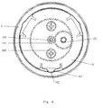
- Fig.4 is a top view of the third embodiment according to the present invention.
- the difference between the earphone line retracting device in the third embodiment and the earphone line retracting device in the first embodiment is that a clutch 6 is arranged between winder 2 and decelerator means 3, and winder 2 is connected to decelerator means 3 by clutch 6.
- Inside clutch 6 is provided with gear engaging gear 152.
- Outside clutch 6 is provided with one or plurality of convex 161. Convex 161 engage concave 162 on winder 2.
- Other parts in this embodiment are the same as in first embodiment.
- the convex on the outside of clutch is resilient.
- the convex can be spring sheet.
- the force exerted by concave 162 on convex 161 is bigger than a predetermined threshold.
- the convex 161 causes winder 2 to rotate via concave 162.
- convex 161 stops causing winder 2 to rotate, but causes micromotor to rotate without load, whereby protecting the micromotor effectively from being damaged by over load (the coil of the micromotor may be damaged by over load).
- axis 101 of the micromotor causes the decelerator means to rotate, and finally causes the winder to rotate.
- the micromotor When the retraction of the earphone line is completed, since the user cannot turn off the power instantly, the micromotor continues to rotate. At this time, since the winder cannot continue to rotate, the micromotor is easy to be damaged and the members, such as the earphone line, are easy to be damaged due to over load if there is no clutch, By contrast, in this embodiment, because there is a clutch causing the micromotor to rotate without load, the micromotor and the members are protected effectively. In addition, the clutch can also reduce the resistant force when the user pulls the earphone line out of the winder.
- the winder and the decelerator means disengage the micromotor because of the clutch, and at the same time, the winder rotates to let the line out while the micromotor and the decelerator means remain static.
- the clutch in this embodiment can be a resistance oil clutch.
- the drive means is a spring or a clockwork spring
- the shift gear means connected to the spring or the clockwork spring is accelerator means.
- the structure of the accelerator means is opposite to the structure of the decelerator means in the first embodiment.
- Other parts in this embodiment are the same as in third embodiment.
- the retracting switch of the earphone line retracting device is a press wheel.
- the clutch in this embodiment can be a resistance oil clutch.
- an automatic line retracting earphone in the fifth embodiment of the invention.
- Fig.5 is a view showing the structure of an automatic line retracting earphone of the fifth embodiment according to the present invention.
- an automatic line retracting earphone according to the present invention comprises: a earphone 7 integrally formed with a voice transmitter 8 and a voice receiver 9, a earphone line 10, and an earphone line retracting device comprising a micromotor 1, a winder 2, a decelerator means 3, a signal connector means 4, a clutch 6, and a housing 5.
- earphone 7 in this embodiment is formed with voice transmitter 8 and voice receiver 9, the earphone 7 can be formed with voice transmitter 8 only or formed with voice receiver 9 only.
- a micromotor rotates to directly drive a winder to rotate in order to retract earphone line. Because the micromotor rotates at as high as thousands rpm (rounds per minute) to tens of thousand rpm, the earphone line is retracted instantly by the winder. The too high speed of the retraction of the earphone line may cause damage to the device and to the user.
- decelerator means in which gears engage each other, so that the speed of the winder reduces to a proper and safe range and at the same time increases torque of the motor, whereby solving the problems existing in the prior art.
- earphone line 10 is formed of a plurality of soft wires and tension-enforced fibre strands, and is coated with insulating material with high wearable property.
- the earphone line in this embodiment has a long service life.
- the drive means is a spring or a clockwork spring
- the shift gear means connected to the spring or the clockwork spring is accelerator means.
- the structure of the accelerator means is opposite to the structure of the decelerator means in the fifth embodiment. Other parts in this embodiment are the same as in fifth embodiment.
- accelerator means can increase retracting distance, whereby the earphone line retracted wholly inside the earphone line retracting device.
- a non-radiation wire mobile phone according to the present invention comprises a main body 101 of the mobile phone and an automatic line retracting earphone.
- the automatic line retracting earphone comprises: a micromotor 1, a winder 2, a decelerator means 3, a signal connector means 4, a clutch 6, a earphone line 10, and a earphone 7 formed with a voice transmitter 8 and a voice receiver 9.
- Earphone line 10 is connected to a signal line inside the mobile phone by signal connector means 4.
- the housing of the non-radiation wire mobile phone is provided with a socket 12 for earphone 7.
- Earphone 7 is inserted into socket 12.
- Other parts of the automatic line retracting earphone are arranged in the housing of the mobile phone.
- the earphone line retracting device of the present invention is arranged at the lower part of the mobile phone, the earphone line retracting device can also be arranged in other parts of the mobile phone.
- a micromotor rotates to directly drive a winder to rotate in order to retract earphone line. Because the micromotor rotates at as high as thousands rpm (rounds per minute) to tens of thousand rpm, the earphone line is retracted instantly by the winder. The too high speed of the retraction of the line may cause damage to the device and to the user.
- decelerator means in which gears engage each other, so that the speed of the winder reduces to a proper and safe range and at the same time increases torque of the motor, whereby solving the problems existing in the prior art.
- main body 101 of the mobile phone is provided at its one side with a line groove 13.
- One end of line groove 13 is connected to winder 2, and the other end of line groove 13 is connected to socket 12.
- Earphone line 10 is wound on winder 2 and extends in line groove 13 to connect to earphone 7.
- micromotor 1 and main body 101 of the mobile phone use the same one power source (not shown), and thus another power source for micromotor 1 is not needed.
- the switch of micromotor 1 uses the hang-up key that is used to disconnect the line when the communication on the mobile phone is completed. Therefore, when the communication on the mobile phone is completed, the retraction of the earphone line starts when the user just presses the hang-up key.
- a separate switch of micromotor 1 can be arranged.
- the drive means in the mobile phone is a spring or a clockwork spring
- the shift gear means connected to the spring or the clockwork spring is accelerator means.
- the structure of the accelerator means is opposite to the structure of the decelerator means in the fifth embodiment.
- Other parts in this embodiment are the same as in seventh embodiment.
- accelerator means can increase retracting distance, whereby the earphone line retracted wholly inside the earphone line retracting device.
- an electronic device of the present invention comprises a main body 201 of the electronic device and an automatic line retracting earphone.
- the automatic line retracting earphone comprises: a micromotor 1, a winder 2, a decelerator means 3, a signal connector means 4, a clutch 6, a earphone line 10, and a earphone 7 formed with a voice transmitter 8 and a voice receiver 9.
- Earphone line 10 is connected to a signal line inside the mobile phone by signal connector means 4.
- the housing of the electronic device is provided with a socket 12 for earphone 7.
- Earphone 7 is inserted into socket 12.
- Other parts of the automatic line retracting earphone are arranged in the housing of the electronic device.
- the earphone line retracting device of the present invention is arranged at the lower part of the electronic device, the earphone line retracting device can also be arranged in other parts of the electronic device.
- the drive means in the electronic device is a spring or a clockwork spring
- the shift gear means connected to the spring or the clockwork spring is accelerator means.
- the structure of the accelerator means is opposite to the structure of the decelerator means in the ninth embodiment. Other parts in this embodiment are the same as in the ninth embodiment.
Landscapes
- Headphones And Earphones (AREA)
- Telephone Set Structure (AREA)
- Physics & Mathematics (AREA)
- Engineering & Computer Science (AREA)
- Acoustics & Sound (AREA)
- Signal Processing (AREA)
Abstract
Description
- The present invention relates to an earphone line retracting device, an automatic line retracting earphone, a non-radiation wire mobile phone and an electronic device.
- With the extensive application of electronic products such as mobile phones, laptop computers, and the products with capability of aiding hearing, etc., it has been found that the earphone of the above products has problems of winding, knotting, and inconvenience of taking and keeping in use, which has caused some troubles to users and even further made some users give up using earphone. In addition, when using the electronic products, the users cannot avoid electromagnetic radiation resulting from the electronic products, causing harm to the users' health. For example, when the user puts the mobile phone on his ear to communicate with other person, the electromagnetic radiation resulting from the mobile phone causes harm to the user's brain. It has been found from experiments and study that the harm resulting from electromagnetic radiation to the brain is reduced dramatically when the mobile phone keeps a distance away from the ear by, for example, replacing the speaker inside the mobile phone with a earphone. By this way, the harm resulting from electromagnetic radiation to the brain is reduced 99%.
- Chinese patent No.
200510004919.9 - In order to solve the above problems, the object of the present invention is to provide an earphone line retracting device to solve the problem existing in the prior art that the speed of the winder is high, the torque of the winder is not big enough, or the winding distance is short when the drive means directly drives the winder.
- Another object of the present invention is to provide an automatic line retracting earphone having the earphone line retracting device.
- Another object of the present invention is to provide a non-radiation wire mobile phone having the automatic line retracting earphone.
- Another object of the present invention is to provide an electronic device having the automatic line retracting earphone.
- In order to solve the above problems, an earphone line retracting device according to the present invention at least comprises: a winder, drive means driving the winder, and signal connector means, characterized in that the earphone line retracting device further comprises shift gear means, by which the drive means drives the winder.
- Preferably, a clutch is arranged between the shift gear means and the winder, the winder connected to the shift gear means by the clutch.
- Preferably, the drive means is a micromotor, the shift gear means is decelerator means.
- Preferably, the drive means is a spring or a clockwork spring, the shift gear means is accelerator means.
- Further, the winder has an inside space, the drive means positioned in the inside space.
- Preferably, the shift gear means has at least two gears, adjacent gears engaging each other.
- Preferably, the signal connector means comprises a circuit board and a plurality of annular conductive sheets, and connects to outside signal by spring feeler and its lead wire.
- Preferably, the signal connector means is a wirelessly connected signal connector means.
- Preferably, the clutch is a resistance oil clutch.
- Preferably, the earphone line retracting device is built in the housing of an electronic device.
- Preferably, when the drive means is a micromotor, the power source of the earphone line retracting device is also the power source of the electronic device in which the earphone line retracting device is built.
- Preferably, when the drive means is a spring or a clockwork spring, the retracting switch of the earphone line is a press wheel.
- An automatic line retracting earphone according to the present invention comprises: an earphone, an earphone line, and an earphone line retracting device described above.
- A non-radiation wire mobile phone according to the present invention comprises: a main body of the mobile phone, an earphone, an earphone line, and an earphone line retracting device. The housing of the non-radiation wire mobile phone is provided with a socket for the earphone. The earphone can be removably inserted into the socket. The earphone line and the earphone line retracting device are arranged in the housing of the mobile phone. The earphone line retracting device at least comprises a winder, drive means driving the winder, and signal connector means. The earphone is provided with a voice transmitter. The earphone is formed integrally with the voice transmitter and a voice receiver. The non-radiation wire mobile phone according to the present invention is characterized in that:
- the earphone line retracting device further comprises shift gear means, by which the drive means drives the winder.
- An electronic device according to the present invention comprises: a main body of the electronic device, an earphone, an earphone line, and an earphone line retracting device. The housing of the electronic device is provided with a socket for the earphone. The earphone can be inserted into the socket. The earphone line and the earphone line retracting device are arranged in the housing of the mobile phone. The earphone line retracting device at least comprises a winder, drive means driving the winder, and signal connector means. The electronic device according to the present invention is characterized in that:
- the earphone line retracting device further comprises shift gear means, by which the drive means drives the winder.
-
-
Fig.1 is a view showing the structure of an earphone line retracting device of the first embodiment according to the present invention. -
Fig.2 is a top view of the earphone line retracting device of the first embodiment according to the present invention. -
Fig.3 is a view showing the structure of a signal connector means of the earphone line retracting device of the first embodiment according to the present invention. -
Fig.4 is a top view of an earphone line retracting device of the third embodiment according to the present invention. -
Fig.5 is a view showing the structure of an automatic line retracting earphone of the fifth embodiment according to the present invention. -
Fig.6 is a view showing the structure of a non-radiation wire mobile phone of the seventh embodiment according to the present invention. -
Fig.7 is a view showing the structure of an electronic device of the ninth embodiment according to the present invention. - The detailed description of the present invention is made by reference to the drawings.
-
Fig.1 is a view showing the structure of an earphone line retracting device of the first embodiment according to the present invention. As shown inFig. 1 , an earphone line retracting device comprises: amicromotor 1, awinder 2, a decelerator means 3, signal connector means 4, and ahousing 5. When the earphone line retracting device is put inside an electronic device, the housing is not needed. As shown inFig. 1 , in this embodiment, in order to reduce the size of the earphone line retracting device, there is a space inwinder 2 in whichmicromotor 1 is positioned. Alternatively, there is not a space inwinder 2, and in this case,micromotor 1 is positioned outsidewinder 2. -
Fig.2 is a top view of the earphone line retracting device of the first embodiment according to the present invention. As shown inFig. 2 , decelerator means 3 comprisesgear 151 andgear 152.Gear 152 connects towinder 2 by its outer teeth.Gear 151 andgear 152 engage each other and are mounted ondrive axis 101 ofmicromotor 1. Whendrive axis 101 rotates,gear 151 andgear 152 rotate, causingwinder 2 to rotate.Nut 103 is used to fix decelerator means 3 andmicromotor 1. - It is understood that
gear 151 andgear 152 in decelerator means 3 shown inFig. 2 are used to illustrate the embodiment. The persons skilled in the art can determine the number and the size of the gear, and determine the position relationship of the micromotor and the winder according to the practical needs. The embodiment of the present invention does not intend to make limitations. For example, the gear can be three or more in which the gears are arranged in a proportion and two adjacent gears engage each other. -
Fig. 3 shows the other side ofwinder 2, namely, the structure of a signal connector means 4. As shown inFig. 3 , signal connector means 4 in the embodiment comprises acircuit board 220 and a plurality of annularconductive sheets 230. The plurality of annularconductive sheets 230 are connected to one end of the earphone line, and are connected to outside signal line (when signal connector means 4 is arranged in an electronic device, the outside signal line is the signal line inside of the electronic device) byspring feeler 231 and lead wire (not shown). In the structure described above, whenwinder 2 rotates to cause the earphone line to wind or spread, one end of the earphone line keeps connected to the outside signal by annularconductive sheets 230 andspring feeler 231, whereby maintaining connection and effectiveness of the signal. It is understood that the signal connector means in the present invention can be wireless signal connector means. - According to the earphone line retracting device of the present invention, when
micromotor 1 rotates,gear 151 andgear 152 connected tomicromotor 1 rotate, causingwinder 2 to rotate, whereby achieving the effect of low speed and high torque. - In the prior art, a micromotor rotates to directly drive a winder to rotate in order to retract earphone line. Because the micromotor rotates at as high as thousands rpm (rounds per minute) to tens of thousand rpm, the earphone line is retracted instantly by the winder. The too high speed of the retraction of the line may cause damage to the device and to the user. By contrast, in the present invention, there is decelerator means in which gears engage each other, so that the speed of the winder reduces to a proper and safe range and at the same time increases torque of the motor, whereby solving the problems existing in the prior art.
- The following is another embodiment of the invention. In this embodiment, the drive means is a spring or a clockwork spring, and the shift gear means connected to the spring or the clockwork spring is accelerator means. The structure of the accelerator means is opposite to the structure of the decelerator means in the first embodiment, namely, the number of the teeth of the gear on the side of the spring or the clockwork spring is less than the number of the teeth of the gear on the side of the winder. Other parts in this embodiment are the same as in first embodiment. In addition, in this embodiment, the retracting switch of the earphone line retracting device is a press wheel. The description of the press wheel can be found in Chinese patent No.
200510004919.9 - The following is another embodiment of the invention.
Fig.4 is a top view of the third embodiment according to the present invention. As shown in the figure, the difference between the earphone line retracting device in the third embodiment and the earphone line retracting device in the first embodiment is that aclutch 6 is arranged betweenwinder 2 and decelerator means 3, andwinder 2 is connected to decelerator means 3 byclutch 6. Inside clutch 6 is provided withgear engaging gear 152. Outside clutch 6 is provided with one or plurality of convex 161.Convex 161 engage concave 162 onwinder 2. Other parts in this embodiment are the same as in first embodiment. - Preferably, the convex on the outside of clutch is resilient. For example, the convex can be spring sheet.
- The force exerted by concave 162 on convex 161 is bigger than a predetermined threshold. The convex 161 causes
winder 2 to rotate via concave 162. When the force exerted by concave 162 on convex 161 is smaller than a predetermined threshold, convex 161stops causing winder 2 to rotate, but causes micromotor to rotate without load, whereby protecting the micromotor effectively from being damaged by over load (the coil of the micromotor may be damaged by over load). When the earphone line is retracted in the second embodiment,axis 101 of the micromotor causes the decelerator means to rotate, and finally causes the winder to rotate. When the retraction of the earphone line is completed, since the user cannot turn off the power instantly, the micromotor continues to rotate. At this time, since the winder cannot continue to rotate, the micromotor is easy to be damaged and the members, such as the earphone line, are easy to be damaged due to over load if there is no clutch, By contrast, in this embodiment, because there is a clutch causing the micromotor to rotate without load, the micromotor and the members are protected effectively. In addition, the clutch can also reduce the resistant force when the user pulls the earphone line out of the winder. For example, when the user pulls the earphone out, the winder and the decelerator means disengage the micromotor because of the clutch, and at the same time, the winder rotates to let the line out while the micromotor and the decelerator means remain static. - Further, the clutch in this embodiment can be a resistance oil clutch.
- The following is another embodiment of the invention. In this embodiment, the drive means is a spring or a clockwork spring, and the shift gear means connected to the spring or the clockwork spring is accelerator means. The structure of the accelerator means is opposite to the structure of the decelerator means in the first embodiment. Other parts in this embodiment are the same as in third embodiment. In addition, in this embodiment, the retracting switch of the earphone line retracting device is a press wheel. In addition, the clutch in this embodiment can be a resistance oil clutch. In addition, when the retraction of the earphone line is completed, the winder disengages the drive means via the clutch, whereby avoiding damaging the members such as earphone line, etc. In addition, when the earphone line is pulled out of the winder, the resistant force is also reduced.
- The following is description of an automatic line retracting earphone in the fifth embodiment of the invention.
Fig.5 is a view showing the structure of an automatic line retracting earphone of the fifth embodiment according to the present invention. As shown inFig. 5 , an automatic line retracting earphone according to the present invention comprises: aearphone 7 integrally formed with avoice transmitter 8 and avoice receiver 9, aearphone line 10, and an earphone line retracting device comprising amicromotor 1, awinder 2, a decelerator means 3, a signal connector means 4, aclutch 6, and ahousing 5. Althoughearphone 7 in this embodiment is formed withvoice transmitter 8 andvoice receiver 9, theearphone 7 can be formed withvoice transmitter 8 only or formed withvoice receiver 9 only. - In the prior art, a micromotor rotates to directly drive a winder to rotate in order to retract earphone line. Because the micromotor rotates at as high as thousands rpm (rounds per minute) to tens of thousand rpm, the earphone line is retracted instantly by the winder. The too high speed of the retraction of the earphone line may cause damage to the device and to the user. By contrast, in the present invention, there is decelerator means in which gears engage each other, so that the speed of the winder reduces to a proper and safe range and at the same time increases torque of the motor, whereby solving the problems existing in the prior art.
- In addition, in this embodiment,
earphone line 10 is formed of a plurality of soft wires and tension-enforced fibre strands, and is coated with insulating material with high wearable property. The earphone line in this embodiment has a long service life. - The following is another embodiment of the invention. In this embodiment, the drive means is a spring or a clockwork spring, and the shift gear means connected to the spring or the clockwork spring is accelerator means. The structure of the accelerator means is opposite to the structure of the decelerator means in the fifth embodiment. Other parts in this embodiment are the same as in fifth embodiment. In addition, in this embodiment, accelerator means can increase retracting distance, whereby the earphone line retracted wholly inside the earphone line retracting device.
- The following is description of a non-radiation wire mobile phone in the seventh embodiment of the invention.
Fig.6 is a view showing the structure of a non-radiation wire mobile phone of the seventh embodiment according to the present invention. As shown in the figure, a non-radiation wire mobile phone according to the present invention comprises amain body 101 of the mobile phone and an automatic line retracting earphone. The automatic line retracting earphone comprises: amicromotor 1, awinder 2, a decelerator means 3, a signal connector means 4, aclutch 6, aearphone line 10, and aearphone 7 formed with avoice transmitter 8 and avoice receiver 9.Earphone line 10 is connected to a signal line inside the mobile phone by signal connector means 4. In addition, the housing of the non-radiation wire mobile phone is provided with asocket 12 forearphone 7.Earphone 7 is inserted intosocket 12. Other parts of the automatic line retracting earphone are arranged in the housing of the mobile phone. Although the earphone line retracting device of the present invention is arranged at the lower part of the mobile phone, the earphone line retracting device can also be arranged in other parts of the mobile phone. - In the prior art, a micromotor rotates to directly drive a winder to rotate in order to retract earphone line. Because the micromotor rotates at as high as thousands rpm (rounds per minute) to tens of thousand rpm, the earphone line is retracted instantly by the winder. The too high speed of the retraction of the line may cause damage to the device and to the user. By contrast, in the present invention, there is decelerator means in which gears engage each other, so that the speed of the winder reduces to a proper and safe range and at the same time increases torque of the motor, whereby solving the problems existing in the prior art.
- In addition, as shown in the figure, in this embodiment,
main body 101 of the mobile phone is provided at its one side with aline groove 13. One end ofline groove 13 is connected towinder 2, and the other end ofline groove 13 is connected tosocket 12.Earphone line 10 is wound onwinder 2 and extends inline groove 13 to connect toearphone 7. - In addition, in this embodiment,
micromotor 1 andmain body 101 of the mobile phone use the same one power source (not shown), and thus another power source formicromotor 1 is not needed. - In addition, in this embodiment, the switch of
micromotor 1 uses the hang-up key that is used to disconnect the line when the communication on the mobile phone is completed. Therefore, when the communication on the mobile phone is completed, the retraction of the earphone line starts when the user just presses the hang-up key. Alternatively, a separate switch ofmicromotor 1 can be arranged. - The following is another embodiment of the invention. In this embodiment, the drive means in the mobile phone is a spring or a clockwork spring, and the shift gear means connected to the spring or the clockwork spring is accelerator means. The structure of the accelerator means is opposite to the structure of the decelerator means in the fifth embodiment. Other parts in this embodiment are the same as in seventh embodiment. In addition, in this embodiment, accelerator means can increase retracting distance, whereby the earphone line retracted wholly inside the earphone line retracting device.
- The following is description of an electronic device in the ninth embodiment of the invention.
Fig.7 is a view showing the structure of an electronic device of the ninth embodiment according to the present invention. In this embodiment, the electronic device can be any electronic devices, such as MP4 serial products, personal computers, hand game players, etc, which use earphone. As shown in the figure, an electronic device of the present invention comprises amain body 201 of the electronic device and an automatic line retracting earphone. The automatic line retracting earphone comprises: amicromotor 1, awinder 2, a decelerator means 3, a signal connector means 4, aclutch 6, aearphone line 10, and aearphone 7 formed with avoice transmitter 8 and avoice receiver 9.Earphone line 10 is connected to a signal line inside the mobile phone by signal connector means 4. In addition, the housing of the electronic device is provided with asocket 12 forearphone 7.Earphone 7 is inserted intosocket 12. Other parts of the automatic line retracting earphone are arranged in the housing of the electronic device. Although the earphone line retracting device of the present invention is arranged at the lower part of the electronic device, the earphone line retracting device can also be arranged in other parts of the electronic device. - The following is another embodiment of the invention. In this embodiment, the drive means in the electronic device is a spring or a clockwork spring, and the shift gear means connected to the spring or the clockwork spring is accelerator means. The structure of the accelerator means is opposite to the structure of the decelerator means in the ninth embodiment. Other parts in this embodiment are the same as in the ninth embodiment.
Claims (35)
- An earphone line retracting device at least comprising: a winder, drive means driving the winder, and signal connector means, characterized in that the earphone line retracting device further comprises shift gear means, by which the drive means drives the winder.
- An earphone line retracting device according to claim 1, characterized in that a clutch is arranged between the shift gear means and the winder, the winder connected to the shift gear means by the clutch.
- An earphone line retracting device according to claim 1 or claim 2, characterized in that the drive means is a micromotor, the shift gear means is decelerator means.
- An earphone line retracting device according to claim 1 or claim 2, characterized in that the drive means is a spring or a clockwork spring, the shift gear means is accelerator means.
- An earphone line retracting device according to claim 1 or claim 2, characterized in that the winder has an inside space, the drive means positioned in the inside space.
- An earphone line retracting device according to claim 1 or claim 2, characterized in that the shift gear means has at least two gears, adjacent gears engaging each other.
- An earphone line retracting device according to claim 1 or claim 2, characterized in that the signal connector means comprises a circuit board and a plurality of annular conductive sheets, and connects to outside signal by spring feeler and its lead wire.
- An earphone line retracting device according to claim 1 or claim 2, characterized in that the signal connector means is a wirelessly connected signal connector means.
- An earphone line retracting device according to claim 2, characterized in that the clutch is a resistance oil clutch.
- An earphone line retracting device according to claim 1 or claim 2, characterized in that the earphone line retracting device is built in the housing of an electronic device.
- An earphone line retracting device according to claim 3, characterized in that the power source for the earphone line retracting device is the power source for the electronic device in which the earphone line retracting device is built.
- An earphone line retracting device according to claim 4, characterized in that the retracting switch of the earphone line of the earphone line retracting device is a press wheel.
- An automatic line retracting earphone comprising: an earphone, an earphone line, and an earphone line retracting device, characterized in that the earphone line retracting device is the earphone line retracting device in any one of claims 1-12.
- An automatic line retracting earphone according to claim 13, characterized in that the earphone is provided with a voice transmitter, and the earphone is formed integrally with the voice transmitter and a voice receiver.
- An automatic line retracting earphone according to claim 13, characterized in that the earphone line is formed of a plurality of soft wires and tension-enforced fibre strands, and is coated with insulating material with high wearable property.
- A non-radiation wire mobile phone comprising: a main body of the mobile phone, an earphone, an earphone line, and an earphone line retracting device, the housing of the non-radiation wire mobile phone provided with a socket for the earphone, the earphone removable inserted into the socket, the earphone line and the earphone line retracting device arranged in the housing of the mobile phone, the earphone line retracting device at least comprising a winder, drive means driving the winder, and signal connector means, the earphone provided with a voice transmitter, and the earphone formed integrally with the voice transmitter and a voice receiver, characterized in that:the earphone line retracting device further comprises shift gear means, by which the drive means drives the winder.
- A non-radiation wire mobile phone according to claim 16, characterized in that: a clutch is arranged between the shift gear means and the winder, the winder connected to the shift gear means by the clutch.
- A non-radiation wire mobile phone according to claim 16 or claim 17, characterized in that the drive means is a micromotor, the shift gear means is decelerator means.
- A non-radiation wire mobile phone according to claim 16 or claim 17, characterized in that the drive means is a spring or a clockwork spring, the shift gear means is accelerator means.
- A non-radiation wire mobile phone according to claim 16 or claim 17, characterized in that the winder has an inside space, the drive means positioned in the inside space.
- A non-radiation wire mobile phone according to claim 16 or claim 17, characterized in that the shift gear means has at least two gears, adjacent gears engaging each other.
- A non-radiation wire mobile phone according to claim 16 or claim 17, characterized in that the signal connector means comprises a circuit board and a plurality of annular conductive sheets, and connects to outside signal by spring feeler and its lead wire.
- A non-radiation wire mobile phone according to claim 16 or claim 17, characterized in that the signal connector means is a wirelessly connected signal connector means.
- A non-radiation wire mobile phone according to claim 16 or claim 17, characterized in that the non-radiation wire mobile phone is provided at its one side with a line groove, one end of the line groove connected to the winder, the other end of the line groove connected to the socket, the earphone line wound on the winder and extending in the line groove to connect to the earphone.
- A non-radiation wire mobile phone according to claim 16 or claim 17, characterized in that the earphone line is formed of a plurality of soft wires and tension-enforced fibre strands, and is coated with insulating material with high wearable property.
- A non-radiation wire mobile phone according to claim 17, characterized in that the clutch is a resistance oil clutch.
- A non-radiation wire mobile phone according to claim 17, characterized in that the micromotor and the main body of the mobile phone use the same one power source.
- A non-radiation wire mobile phone according to claim 17, characterized in that the switch of the micromotor uses the hang-up key that is used to disconnect the line when the communication on the mobile phone is completed.
- An electronic device comprising: a main body of the electronic device, an earphone, an earphone line, and an earphone line retracting device, the housing of the electronic device provided with a socket for the earphone, the earphone removably inserted into the socket, the earphone line and the earphone line retracting device arranged in the housing of the electronic device, the earphone line retracting device at least comprising a winder, drive means driving the winder, and signal connector means, characterized in that:the earphone line retracting device further comprises shift gear means, by which the drive means drives the winder.
- An electronic device according to claim 29, characterized in that a clutch is arranged between the shift gear means and the winder, the winder connected to the shift gear means by the clutch.
- An electronic device according to claim 29 or claim 30, characterized in that the drive means is a micromotor, the shift gear means is decelerator means.
- An electronic device according to claim 29 or claim 30, characterized in that the drive means is a spring or a clockwork spring, the shift gear means is accelerator means.
- An electronic device according to claim 29 or claim 30, characterized in that the electronic device is MP4 serial products.
- An electronic device according to claim 29 or claim 30, characterized in that the electronic device is a personal computer.
- An electronic device according to claim 29 or claim 30, characterized in that the electronic device is a hand game player.
Applications Claiming Priority (1)
| Application Number | Priority Date | Filing Date | Title |
|---|---|---|---|
| CN2008101831863A CN101442693B (en) | 2008-03-10 | 2008-12-15 | Wire-restoring device for earphone cord, automatic wire-restoring earphone, non-radiation wired mobile phone and electronic equipment |
Publications (3)
| Publication Number | Publication Date |
|---|---|
| EP2197079A2 true EP2197079A2 (en) | 2010-06-16 |
| EP2197079A3 EP2197079A3 (en) | 2011-05-11 |
| EP2197079B1 EP2197079B1 (en) | 2015-04-15 |
Family
ID=42031897
Family Applications (1)
| Application Number | Title | Priority Date | Filing Date |
|---|---|---|---|
| EP09150086.8A Active EP2197079B1 (en) | 2008-12-15 | 2009-01-06 | Earphone line retracting device, automatic line retracting earphone, non-radiation wire mobile phone and electronic device |
Country Status (6)
| Country | Link |
|---|---|
| EP (1) | EP2197079B1 (en) |
| JP (1) | JP2010141864A (en) |
| KR (1) | KR101043505B1 (en) |
| BR (1) | BRPI0900150A2 (en) |
| ES (1) | ES2538811T3 (en) |
| RU (1) | RU2492582C2 (en) |
Cited By (2)
| Publication number | Priority date | Publication date | Assignee | Title |
|---|---|---|---|---|
| US8870111B2 (en) | 2012-03-28 | 2014-10-28 | Delta Electronics (Thailand) Public Co., Ltd. | Cable winding device and fixing and winding mechanism thereof |
| CN115196444A (en) * | 2022-08-23 | 2022-10-18 | 武汉华宇科技发展有限公司 | Speed reduction take-up device |
Families Citing this family (6)
| Publication number | Priority date | Publication date | Assignee | Title |
|---|---|---|---|---|
| KR101303274B1 (en) | 2010-11-04 | 2013-09-03 | 신지앙 티안디 그룹 | Built-in type expansion and contraction earphone structure, and terminal device |
| US9319505B2 (en) * | 2011-06-10 | 2016-04-19 | Xinjiang Tiandi Group | Terminal equipment with built-in retractable headset |
| KR101231783B1 (en) | 2012-12-06 | 2013-02-14 | 이승수 | Cellphone case with earphones automatic detachable portion |
| KR101918895B1 (en) | 2018-04-02 | 2018-11-14 | 울산시설공단 | Automatic cable winding device |
| WO2022055497A1 (en) * | 2020-09-11 | 2022-03-17 | Hewlett-Packard Development Company, L.P. | Removable input/output modules |
| KR20240081793A (en) | 2022-12-01 | 2024-06-10 | 김도희 | pulley charger |
Citations (2)
| Publication number | Priority date | Publication date | Assignee | Title |
|---|---|---|---|---|
| US6858951B2 (en) | 2001-10-10 | 2005-02-22 | Sheng Hsin Liao | Wire rewinding box with recharge unit |
| CN101237713A (en) | 2008-03-10 | 2008-08-06 | 新疆天地集团有限公司 | An earphone line collection device, a earphone assembly and a mobile terminal |
Family Cites Families (20)
| Publication number | Priority date | Publication date | Assignee | Title |
|---|---|---|---|---|
| JPS5617779A (en) * | 1979-07-17 | 1981-02-19 | Mitsui Eng & Shipbuild Co Ltd | Structure of ship using coal as fuel |
| JPH01144504A (en) * | 1987-11-30 | 1989-06-06 | Fujikura Ltd | Insulated cable |
| US4882709A (en) * | 1988-08-25 | 1989-11-21 | Integrated Device Technology, Inc. | Conditional write RAM |
| JP2825283B2 (en) * | 1989-08-21 | 1998-11-18 | 日本臓器製薬株式会社 | Vascular disorder judgment method |
| JPH07143214A (en) * | 1993-11-19 | 1995-06-02 | Sony Corp | Mobile phone |
| JPH0898291A (en) * | 1994-09-26 | 1996-04-12 | Aiwa Co Ltd | Earphone housing device |
| JPH10297836A (en) | 1997-04-28 | 1998-11-10 | Sony Corp | Electric cord storage |
| JPH11298983A (en) * | 1998-04-15 | 1999-10-29 | Sony Corp | Monaural earphones |
| JP2000063047A (en) | 1998-08-25 | 2000-02-29 | Marusu Denshi:Kk | Cord relay device and cord reel device employing said cord relay device |
| JP2001127864A (en) * | 1999-10-29 | 2001-05-11 | Suriibii Enterprises Japan:Kk | Earphone microphone for mobile phone and mobile phone |
| JP4447766B2 (en) * | 2000-11-17 | 2010-04-07 | 株式会社イー・エム・テクノ | Electromagnetic radiation suppressor and earphone provided with electromagnetic radiation suppressor |
| JP2002171326A (en) * | 2000-12-01 | 2002-06-14 | Tomoyuki Samoto | Portable telephone set |
| US7257422B2 (en) * | 2001-09-24 | 2007-08-14 | Loprete Joseph A | Portable radiotelephone apparatus |
| CN101827074B (en) * | 2003-10-29 | 2013-07-31 | 高通股份有限公司 | High data rate interface |
| CN1295915C (en) * | 2005-01-28 | 2007-01-17 | 新疆天地集团有限公司 | Mobile phone with built-in earphone for preventing radiation and built-in earphone assembly for preventing radiation |
| JP2007173089A (en) * | 2005-12-22 | 2007-07-05 | Sdk Kk | Parallel cord and portable audio equipment using it |
| KR100800103B1 (en) * | 2007-02-01 | 2008-01-31 | 디지아나 주식회사 | headset |
| JP2008269799A (en) * | 2007-04-16 | 2008-11-06 | Ltk Technologies Kk | Parallel flexible cable, and earphone antenna |
| CN201075199Y (en) * | 2007-06-25 | 2008-06-18 | 陶国胜 | Poly syncretism computer remote controller |
| JP3140018U (en) * | 2007-11-29 | 2008-03-13 | 權威電科技有限公司 | Line box with music player |
-
2009
- 2009-01-06 ES ES09150086.8T patent/ES2538811T3/en active Active
- 2009-01-06 EP EP09150086.8A patent/EP2197079B1/en active Active
- 2009-01-07 JP JP2009001570A patent/JP2010141864A/en active Pending
- 2009-01-08 BR BRPI0900150-6A patent/BRPI0900150A2/en not_active IP Right Cessation
- 2009-01-09 KR KR1020090001905A patent/KR101043505B1/en not_active Expired - Fee Related
- 2009-01-11 RU RU2009100055/28A patent/RU2492582C2/en active
Patent Citations (2)
| Publication number | Priority date | Publication date | Assignee | Title |
|---|---|---|---|---|
| US6858951B2 (en) | 2001-10-10 | 2005-02-22 | Sheng Hsin Liao | Wire rewinding box with recharge unit |
| CN101237713A (en) | 2008-03-10 | 2008-08-06 | 新疆天地集团有限公司 | An earphone line collection device, a earphone assembly and a mobile terminal |
Cited By (3)
| Publication number | Priority date | Publication date | Assignee | Title |
|---|---|---|---|---|
| US8870111B2 (en) | 2012-03-28 | 2014-10-28 | Delta Electronics (Thailand) Public Co., Ltd. | Cable winding device and fixing and winding mechanism thereof |
| EP2645508B1 (en) * | 2012-03-28 | 2018-03-14 | Delta Electronics (Thailand) Public Co., Ltd. | Cable winding device and fixing and winding mechanism thereof |
| CN115196444A (en) * | 2022-08-23 | 2022-10-18 | 武汉华宇科技发展有限公司 | Speed reduction take-up device |
Also Published As
| Publication number | Publication date |
|---|---|
| KR20100069533A (en) | 2010-06-24 |
| EP2197079A3 (en) | 2011-05-11 |
| RU2009100055A (en) | 2010-07-20 |
| KR101043505B1 (en) | 2011-06-23 |
| JP2010141864A (en) | 2010-06-24 |
| ES2538811T3 (en) | 2015-06-24 |
| EP2197079B1 (en) | 2015-04-15 |
| RU2492582C2 (en) | 2013-09-10 |
| BRPI0900150A2 (en) | 2011-10-11 |
Similar Documents
| Publication | Publication Date | Title |
|---|---|---|
| US8165646B2 (en) | Earphone line retracting device, automatic line retracting earphone, non-radiation wire mobile phone and electronic device | |
| EP2197079B1 (en) | Earphone line retracting device, automatic line retracting earphone, non-radiation wire mobile phone and electronic device | |
| EP2451189B1 (en) | Built-in telescopic earphone structure and terminal device | |
| US8290547B2 (en) | Protective case having retractable earbuds | |
| US20120224739A1 (en) | Cartridge for Managing Ear Bud Cables Having Annular Audio Contacts | |
| US7125282B2 (en) | Adapter module for portable computer | |
| CN102223587B (en) | An earphone cable take-up device, an earphone assembly and a mobile terminal | |
| CN201422150Y (en) | Earphone wire retracting device, earphone assembly and mobile terminal | |
| US8963007B2 (en) | Earphone line, earphone line take-up apparatus, earphone assembly and mobile terminal | |
| US20090262490A1 (en) | Electronic device | |
| CN101640827B (en) | Earphone wire collection device, earphone assembly and mobile terminal | |
| US20090184190A1 (en) | Reel device with music play function | |
| TWI393314B (en) | Headset line collection device, automatic collection headphones, non-radiation cable mobile phones and electronic equipment | |
| CN102469383B (en) | Main-sub earphone structure and mobile terminal | |
| CN203942625U (en) | Portable split type bluetooth earphone | |
| CN202085290U (en) | Earphone cable take-up device and terminal equipment | |
| CN209881005U (en) | hub | |
| HK1128577B (en) | Wire-receiving device used in an earphone, automatic-wire-receiving earphone, radiationless cellphone and electronic device with connection wires | |
| KR200356185Y1 (en) | Box using as earphone holder and accessary applying to mobile communication terminal | |
| CN202019379U (en) | Cellphone with concealable earphone | |
| KR101507395B1 (en) | Wearable earphone using slapband | |
| CN216852302U (en) | Earphone cord storage box, earphone and audiphone | |
| CN202602858U (en) | Built-in earphone accessory structure | |
| CN211789887U (en) | Patch cord with waterproof function | |
| CN101378600A (en) | Wire-restoring device for earphone line, earphone assembly, non-radiation wired mobile phone and electronic device |
Legal Events
| Date | Code | Title | Description |
|---|---|---|---|
| PUAI | Public reference made under article 153(3) epc to a published international application that has entered the european phase |
Free format text: ORIGINAL CODE: 0009012 |
|
| AK | Designated contracting states |
Kind code of ref document: A2 Designated state(s): AT BE BG CH CY CZ DE DK EE ES FI FR GB GR HR HU IE IS IT LI LT LU LV MC MK MT NL NO PL PT RO SE SI SK TR |
|
| AX | Request for extension of the european patent |
Extension state: AL BA RS |
|
| PUAL | Search report despatched |
Free format text: ORIGINAL CODE: 0009013 |
|
| AK | Designated contracting states |
Kind code of ref document: A3 Designated state(s): AT BE BG CH CY CZ DE DK EE ES FI FR GB GR HR HU IE IS IT LI LT LU LV MC MK MT NL NO PL PT RO SE SI SK TR |
|
| AX | Request for extension of the european patent |
Extension state: AL BA RS |
|
| 17P | Request for examination filed |
Effective date: 20110805 |
|
| AKX | Designation fees paid |
Designated state(s): AT BE BG CH CY CZ DE DK EE ES FI FR GB GR HR HU IE IS IT LI LT LU LV MC MK MT NL NO PL PT RO SE SI SK TR |
|
| 17Q | First examination report despatched |
Effective date: 20140327 |
|
| GRAP | Despatch of communication of intention to grant a patent |
Free format text: ORIGINAL CODE: EPIDOSNIGR1 |
|
| INTG | Intention to grant announced |
Effective date: 20141126 |
|
| GRAS | Grant fee paid |
Free format text: ORIGINAL CODE: EPIDOSNIGR3 |
|
| GRAA | (expected) grant |
Free format text: ORIGINAL CODE: 0009210 |
|
| AK | Designated contracting states |
Kind code of ref document: B1 Designated state(s): AT BE BG CH CY CZ DE DK EE ES FI FR GB GR HR HU IE IS IT LI LT LU LV MC MK MT NL NO PL PT RO SE SI SK TR |
|
| REG | Reference to a national code |
Ref country code: GB Ref legal event code: FG4D Ref country code: CH Ref legal event code: EP |
|
| REG | Reference to a national code |
Ref country code: CH Ref legal event code: NV Representative=s name: LEMAN CONSULTING S.A., CH |
|
| REG | Reference to a national code |
Ref country code: IE Ref legal event code: FG4D |
|
| REG | Reference to a national code |
Ref country code: AT Ref legal event code: REF Ref document number: 722435 Country of ref document: AT Kind code of ref document: T Effective date: 20150515 |
|
| REG | Reference to a national code |
Ref country code: DE Ref legal event code: R096 Ref document number: 602009030627 Country of ref document: DE Effective date: 20150521 |
|
| REG | Reference to a national code |
Ref country code: ES Ref legal event code: FG2A Ref document number: 2538811 Country of ref document: ES Kind code of ref document: T3 Effective date: 20150624 |
|
| REG | Reference to a national code |
Ref country code: NL Ref legal event code: T3 |
|
| REG | Reference to a national code |
Ref country code: SE Ref legal event code: TRGR |
|
| REG | Reference to a national code |
Ref country code: AT Ref legal event code: MK05 Ref document number: 722435 Country of ref document: AT Kind code of ref document: T Effective date: 20150415 |
|
| REG | Reference to a national code |
Ref country code: LT Ref legal event code: MG4D |
|
| PG25 | Lapsed in a contracting state [announced via postgrant information from national office to epo] |
Ref country code: PT Free format text: LAPSE BECAUSE OF FAILURE TO SUBMIT A TRANSLATION OF THE DESCRIPTION OR TO PAY THE FEE WITHIN THE PRESCRIBED TIME-LIMIT Effective date: 20150817 Ref country code: NO Free format text: LAPSE BECAUSE OF FAILURE TO SUBMIT A TRANSLATION OF THE DESCRIPTION OR TO PAY THE FEE WITHIN THE PRESCRIBED TIME-LIMIT Effective date: 20150715 Ref country code: HR Free format text: LAPSE BECAUSE OF FAILURE TO SUBMIT A TRANSLATION OF THE DESCRIPTION OR TO PAY THE FEE WITHIN THE PRESCRIBED TIME-LIMIT Effective date: 20150415 Ref country code: LT Free format text: LAPSE BECAUSE OF FAILURE TO SUBMIT A TRANSLATION OF THE DESCRIPTION OR TO PAY THE FEE WITHIN THE PRESCRIBED TIME-LIMIT Effective date: 20150415 |
|
| PG25 | Lapsed in a contracting state [announced via postgrant information from national office to epo] |
Ref country code: IS Free format text: LAPSE BECAUSE OF FAILURE TO SUBMIT A TRANSLATION OF THE DESCRIPTION OR TO PAY THE FEE WITHIN THE PRESCRIBED TIME-LIMIT Effective date: 20150815 Ref country code: GR Free format text: LAPSE BECAUSE OF FAILURE TO SUBMIT A TRANSLATION OF THE DESCRIPTION OR TO PAY THE FEE WITHIN THE PRESCRIBED TIME-LIMIT Effective date: 20150716 Ref country code: AT Free format text: LAPSE BECAUSE OF FAILURE TO SUBMIT A TRANSLATION OF THE DESCRIPTION OR TO PAY THE FEE WITHIN THE PRESCRIBED TIME-LIMIT Effective date: 20150415 Ref country code: LV Free format text: LAPSE BECAUSE OF FAILURE TO SUBMIT A TRANSLATION OF THE DESCRIPTION OR TO PAY THE FEE WITHIN THE PRESCRIBED TIME-LIMIT Effective date: 20150415 |
|
| REG | Reference to a national code |
Ref country code: FR Ref legal event code: PLFP Year of fee payment: 8 |
|
| REG | Reference to a national code |
Ref country code: DE Ref legal event code: R097 Ref document number: 602009030627 Country of ref document: DE |
|
| PG25 | Lapsed in a contracting state [announced via postgrant information from national office to epo] |
Ref country code: DK Free format text: LAPSE BECAUSE OF FAILURE TO SUBMIT A TRANSLATION OF THE DESCRIPTION OR TO PAY THE FEE WITHIN THE PRESCRIBED TIME-LIMIT Effective date: 20150415 Ref country code: EE Free format text: LAPSE BECAUSE OF FAILURE TO SUBMIT A TRANSLATION OF THE DESCRIPTION OR TO PAY THE FEE WITHIN THE PRESCRIBED TIME-LIMIT Effective date: 20150415 |
|
| PLBE | No opposition filed within time limit |
Free format text: ORIGINAL CODE: 0009261 |
|
| STAA | Information on the status of an ep patent application or granted ep patent |
Free format text: STATUS: NO OPPOSITION FILED WITHIN TIME LIMIT |
|
| PG25 | Lapsed in a contracting state [announced via postgrant information from national office to epo] |
Ref country code: RO Free format text: LAPSE BECAUSE OF NON-PAYMENT OF DUE FEES Effective date: 20150415 Ref country code: CZ Free format text: LAPSE BECAUSE OF FAILURE TO SUBMIT A TRANSLATION OF THE DESCRIPTION OR TO PAY THE FEE WITHIN THE PRESCRIBED TIME-LIMIT Effective date: 20150415 Ref country code: PL Free format text: LAPSE BECAUSE OF FAILURE TO SUBMIT A TRANSLATION OF THE DESCRIPTION OR TO PAY THE FEE WITHIN THE PRESCRIBED TIME-LIMIT Effective date: 20150415 Ref country code: SK Free format text: LAPSE BECAUSE OF FAILURE TO SUBMIT A TRANSLATION OF THE DESCRIPTION OR TO PAY THE FEE WITHIN THE PRESCRIBED TIME-LIMIT Effective date: 20150415 |
|
| 26N | No opposition filed |
Effective date: 20160118 |
|
| PG25 | Lapsed in a contracting state [announced via postgrant information from national office to epo] |
Ref country code: BE Free format text: LAPSE BECAUSE OF NON-PAYMENT OF DUE FEES Effective date: 20160131 Ref country code: SI Free format text: LAPSE BECAUSE OF FAILURE TO SUBMIT A TRANSLATION OF THE DESCRIPTION OR TO PAY THE FEE WITHIN THE PRESCRIBED TIME-LIMIT Effective date: 20150415 |
|
| PG25 | Lapsed in a contracting state [announced via postgrant information from national office to epo] |
Ref country code: BE Free format text: LAPSE BECAUSE OF FAILURE TO SUBMIT A TRANSLATION OF THE DESCRIPTION OR TO PAY THE FEE WITHIN THE PRESCRIBED TIME-LIMIT Effective date: 20150415 Ref country code: LU Free format text: LAPSE BECAUSE OF FAILURE TO SUBMIT A TRANSLATION OF THE DESCRIPTION OR TO PAY THE FEE WITHIN THE PRESCRIBED TIME-LIMIT Effective date: 20160106 |
|
| PG25 | Lapsed in a contracting state [announced via postgrant information from national office to epo] |
Ref country code: MC Free format text: LAPSE BECAUSE OF FAILURE TO SUBMIT A TRANSLATION OF THE DESCRIPTION OR TO PAY THE FEE WITHIN THE PRESCRIBED TIME-LIMIT Effective date: 20150415 |
|
| REG | Reference to a national code |
Ref country code: IE Ref legal event code: MM4A |
|
| REG | Reference to a national code |
Ref country code: FR Ref legal event code: PLFP Year of fee payment: 9 |
|
| PG25 | Lapsed in a contracting state [announced via postgrant information from national office to epo] |
Ref country code: IE Free format text: LAPSE BECAUSE OF NON-PAYMENT OF DUE FEES Effective date: 20160106 |
|
| PG25 | Lapsed in a contracting state [announced via postgrant information from national office to epo] |
Ref country code: MT Free format text: LAPSE BECAUSE OF FAILURE TO SUBMIT A TRANSLATION OF THE DESCRIPTION OR TO PAY THE FEE WITHIN THE PRESCRIBED TIME-LIMIT Effective date: 20150415 |
|
| REG | Reference to a national code |
Ref country code: FR Ref legal event code: PLFP Year of fee payment: 10 |
|
| PG25 | Lapsed in a contracting state [announced via postgrant information from national office to epo] |
Ref country code: HU Free format text: LAPSE BECAUSE OF FAILURE TO SUBMIT A TRANSLATION OF THE DESCRIPTION OR TO PAY THE FEE WITHIN THE PRESCRIBED TIME-LIMIT; INVALID AB INITIO Effective date: 20090106 Ref country code: CY Free format text: LAPSE BECAUSE OF FAILURE TO SUBMIT A TRANSLATION OF THE DESCRIPTION OR TO PAY THE FEE WITHIN THE PRESCRIBED TIME-LIMIT Effective date: 20150415 |
|
| PG25 | Lapsed in a contracting state [announced via postgrant information from national office to epo] |
Ref country code: MT Free format text: LAPSE BECAUSE OF FAILURE TO SUBMIT A TRANSLATION OF THE DESCRIPTION OR TO PAY THE FEE WITHIN THE PRESCRIBED TIME-LIMIT Effective date: 20160131 Ref country code: MK Free format text: LAPSE BECAUSE OF FAILURE TO SUBMIT A TRANSLATION OF THE DESCRIPTION OR TO PAY THE FEE WITHIN THE PRESCRIBED TIME-LIMIT Effective date: 20150415 |
|
| PG25 | Lapsed in a contracting state [announced via postgrant information from national office to epo] |
Ref country code: BG Free format text: LAPSE BECAUSE OF FAILURE TO SUBMIT A TRANSLATION OF THE DESCRIPTION OR TO PAY THE FEE WITHIN THE PRESCRIBED TIME-LIMIT Effective date: 20150415 |
|
| PGFP | Annual fee paid to national office [announced via postgrant information from national office to epo] |
Ref country code: SE Payment date: 20211210 Year of fee payment: 14 Ref country code: FR Payment date: 20211217 Year of fee payment: 14 Ref country code: GB Payment date: 20211209 Year of fee payment: 14 |
|
| PGFP | Annual fee paid to national office [announced via postgrant information from national office to epo] |
Ref country code: CH Payment date: 20211216 Year of fee payment: 14 |
|
| PGFP | Annual fee paid to national office [announced via postgrant information from national office to epo] |
Ref country code: NL Payment date: 20211216 Year of fee payment: 14 |
|
| PGFP | Annual fee paid to national office [announced via postgrant information from national office to epo] |
Ref country code: FI Payment date: 20220110 Year of fee payment: 14 Ref country code: DE Payment date: 20211214 Year of fee payment: 14 |
|
| PGFP | Annual fee paid to national office [announced via postgrant information from national office to epo] |
Ref country code: TR Payment date: 20220105 Year of fee payment: 14 Ref country code: IT Payment date: 20211213 Year of fee payment: 14 Ref country code: ES Payment date: 20220202 Year of fee payment: 14 |
|
| REG | Reference to a national code |
Ref country code: DE Ref legal event code: R119 Ref document number: 602009030627 Country of ref document: DE |
|
| REG | Reference to a national code |
Ref country code: SE Ref legal event code: EUG |
|
| REG | Reference to a national code |
Ref country code: CH Ref legal event code: PL |
|
| REG | Reference to a national code |
Ref country code: NL Ref legal event code: MM Effective date: 20230201 |
|
| GBPC | Gb: european patent ceased through non-payment of renewal fee |
Effective date: 20230106 |
|
| PG25 | Lapsed in a contracting state [announced via postgrant information from national office to epo] |
Ref country code: SE Free format text: LAPSE BECAUSE OF NON-PAYMENT OF DUE FEES Effective date: 20230107 Ref country code: NL Free format text: LAPSE BECAUSE OF NON-PAYMENT OF DUE FEES Effective date: 20230201 Ref country code: LI Free format text: LAPSE BECAUSE OF NON-PAYMENT OF DUE FEES Effective date: 20230131 Ref country code: GB Free format text: LAPSE BECAUSE OF NON-PAYMENT OF DUE FEES Effective date: 20230106 Ref country code: FI Free format text: LAPSE BECAUSE OF NON-PAYMENT OF DUE FEES Effective date: 20230106 Ref country code: DE Free format text: LAPSE BECAUSE OF NON-PAYMENT OF DUE FEES Effective date: 20230801 Ref country code: CH Free format text: LAPSE BECAUSE OF NON-PAYMENT OF DUE FEES Effective date: 20230131 |
|
| PG25 | Lapsed in a contracting state [announced via postgrant information from national office to epo] |
Ref country code: FR Free format text: LAPSE BECAUSE OF NON-PAYMENT OF DUE FEES Effective date: 20230131 |
|
| PG25 | Lapsed in a contracting state [announced via postgrant information from national office to epo] |
Ref country code: IT Free format text: LAPSE BECAUSE OF NON-PAYMENT OF DUE FEES Effective date: 20230106 |
|
| REG | Reference to a national code |
Ref country code: ES Ref legal event code: FD2A Effective date: 20240229 |
|
| PG25 | Lapsed in a contracting state [announced via postgrant information from national office to epo] |
Ref country code: ES Free format text: LAPSE BECAUSE OF NON-PAYMENT OF DUE FEES Effective date: 20230107 |
|
| PG25 | Lapsed in a contracting state [announced via postgrant information from national office to epo] |
Ref country code: ES Free format text: LAPSE BECAUSE OF NON-PAYMENT OF DUE FEES Effective date: 20230107 |