EP2196997A1 - Coupling structure of fuel assembly - Google Patents
Coupling structure of fuel assembly Download PDFInfo
- Publication number
- EP2196997A1 EP2196997A1 EP08866538A EP08866538A EP2196997A1 EP 2196997 A1 EP2196997 A1 EP 2196997A1 EP 08866538 A EP08866538 A EP 08866538A EP 08866538 A EP08866538 A EP 08866538A EP 2196997 A1 EP2196997 A1 EP 2196997A1
- Authority
- EP
- European Patent Office
- Prior art keywords
- lock key
- latch sleeve
- fuel assembly
- coupling structure
- upper nozzle
- Prior art date
- Legal status (The legal status is an assumption and is not a legal conclusion. Google has not performed a legal analysis and makes no representation as to the accuracy of the status listed.)
- Granted
Links
Images




Classifications
-
- G—PHYSICS
- G21—NUCLEAR PHYSICS; NUCLEAR ENGINEERING
- G21C—NUCLEAR REACTORS
- G21C3/00—Reactor fuel elements and their assemblies; Selection of substances for use as reactor fuel elements
- G21C3/30—Assemblies of a number of fuel elements in the form of a rigid unit
- G21C3/32—Bundles of parallel pin-, rod-, or tube-shaped fuel elements
- G21C3/334—Assembling, maintenance or repair of the bundles
-
- G—PHYSICS
- G21—NUCLEAR PHYSICS; NUCLEAR ENGINEERING
- G21C—NUCLEAR REACTORS
- G21C3/00—Reactor fuel elements and their assemblies; Selection of substances for use as reactor fuel elements
- G21C3/30—Assemblies of a number of fuel elements in the form of a rigid unit
- G21C3/32—Bundles of parallel pin-, rod-, or tube-shaped fuel elements
- G21C3/33—Supporting or hanging of elements in the bundle; Means forming part of the bundle for inserting it into, or removing it from, the core; Means for coupling adjacent bundles
- G21C3/3315—Upper nozzle
-
- Y—GENERAL TAGGING OF NEW TECHNOLOGICAL DEVELOPMENTS; GENERAL TAGGING OF CROSS-SECTIONAL TECHNOLOGIES SPANNING OVER SEVERAL SECTIONS OF THE IPC; TECHNICAL SUBJECTS COVERED BY FORMER USPC CROSS-REFERENCE ART COLLECTIONS [XRACs] AND DIGESTS
- Y02—TECHNOLOGIES OR APPLICATIONS FOR MITIGATION OR ADAPTATION AGAINST CLIMATE CHANGE
- Y02E—REDUCTION OF GREENHOUSE GAS [GHG] EMISSIONS, RELATED TO ENERGY GENERATION, TRANSMISSION OR DISTRIBUTION
- Y02E30/00—Energy generation of nuclear origin
- Y02E30/30—Nuclear fission reactors
Definitions
- the present invention relates to a coupling structure of a fuel assembly.
- a fuel assembly of a pressurized-water nuclear reactor is configured of fuel rods 100, an upper nozzle 101, a lower nozzle 102, guide tubes 103, an upper support lattice 104, an intermediate support lattice 105, a lower support lattice 106, and a foreign matter filter.
- the upper support lattice 104 and the intermediate support lattice 105 are mechanically joined to the guide tubes 103, and the lower support lattice 106 is mechanically joined to lower ends of the guide tubes 103 together with the lower nozzle 102.
- the upper support lattice 104, the intermediate support lattice 105, and the lower support lattice 106 hold the fuel rods 100.
- the upper nozzle 101 is joined, by welding, to upper end portions 108 of sleeves 107 attached to the upper support lattice 104. Moreover, the sleeves 107 and the guide tubes 103 are mechanically joined to each other, respectively.
- the upper nozzle 101 of the fuel assembly is required to be detached in a power plant in order to, for example, replace the fuel rod 100 which has been damaged during an operation. Accordingly, the fuel assembly must be designed so that the upper nozzle 101 is detachable.
- the upper nozzle 101 is conventionally joined to the sleeves 107 by welding as described above, and therefore, cannot be easily detached and attached in the power plant.
- a coupling structure of a fuel assembly using a nut 111 is known as an upper nozzle attachment/detachment structure enabling attachment and detachment of the upper nozzle 101.
- a male screw thread 109 is formed on the upper end portion of the guide tube 103.
- the guide member 103 is fastened and fixed in a clamping manner to the nut 111 having a female screw thread 112 formed on its inner surface through a locking cup 110 provided in the upper nozzle 101 (see Patent Document 1 mentioned below).
- a coupling structure of a fuel assembly using a locking ring is known as the upper nozzle attachment/detachment structure.
- a projecting portion is provided on the guide tube 103.
- the locking ring (omitted from the drawings) is attached to the upper nozzle 101 and is rotated with the projecting portion being inserted into an opening portion of the locking ring.
- the projecting portion of the guide tube 103 overlaps a receiver portion of the locking ring, and the guide tube 103 and the upper nozzle 101 are thus coupled to each other (see Patent Document 2 mentioned below).
- the detached nut 111 may fall and be mixed into the fuel during work, which can be a cause of foreign matter damage.
- a gap is formed between the bottom surface of the projecting portion of the guide tube 103 and the receiver portion of the locking ring, within manufacturing tolerances of each of the guide tube 103 and the locking ring.
- a vertical play is generated at the fitting portion between the projecting portion of the guide tube 103 and the locking ring, that is, the attachment/detachment portion of the upper nozzle.
- an object of the present invention is to provide a coupling structure of a fuel assembly which eliminates a factor leading to mixing of a detached component in the fuel assembly by eliminating the need for disassembling components at the time of attachment and detachment of an upper nozzle, and in which no vertical play is generated at an attachment/detachment portion of the upper nozzle.
- a first aspect of the present invention provides a coupling structure of a fuel assembly including: a latch sleeve having a projecting portion formed at an upper end portion thereof; an upper nozzle having formed therein a latch sleeve installation hole into which the upper end portion of the latch sleeve is inserted; and a lock key which is installed inside the latch sleeve installation hole, and which has an opening portion formed in a bottom surface thereof, the opening portion having a shape corresponding to the projecting portion.
- the latch sleeve and the lock key are coupled to each other by rotating the lock key with the upper end portion of the latch sleeve being inserted into the lock key.
- the coupling structure of the fuel assembly characterized by including a screw coupling means for screw-coupling the lock key to the upper nozzle side with a male screw thread formed on a side surface of the lock key.
- a second aspect of the present invention provides the coupling structure of a fuel assembly according to the first aspect of the present invention, which is characterized in that the screw coupling means screw-couples the lock key and the latch sleeve installation hole with a female screw thread formed on an inner surface of the latch sleeve installation hole.
- a third aspect of the present invention provides the coupling structure of a fuel assembly according to the first aspect of the present invention, which is characterized in that : the screw coupling means includes a cylindrical thick-walled pipe installed in the latch sleeve installation hole, the thick-walled pipe having a female screw thread thread formed in an inner surface thereof; and the screw coupling means screw-couples the lock key and the thick-walled pipe by installing the lock key in the thick-walled pipe.
- a coupling structure of a fuel assembly is achieved which eliminates a factor leading to mixing of a detached component in the fuel assembly since there is no need to disassemble the components at the time of attachment and detachment of the upper nozzle, and in which no vertical play is generated at an attachment/detachment portion of the upper nozzle.
- FIG. 4 parts (a) and (c) of Fig. 4 are side views of the latch sleeve; part (b) of Fig. 4 is a top view of the latch sleeve; and part (d) of Fig. 4 is a cross-sectional view of the latch sleeve taken along a cross section A-A shown in part (b) of Fig. 4 .
- a latch sleeve 10 is cylindrical, and includes a projecting portion 11 formed at an upper end portion of the latch sleeve 10, the projecting portion 11 having a shape of a square with its corners rounded when viewed from the top.
- a flange portion 12 is formed at a portion below the latch sleeve projecting portion 11. The flange portion 12 vertically fixes the latch sleeve 10 with a later-described upper nozzle 30 (see Fig. 6 ) or with a thick-walled pipe 40 that is inserted into the upper nozzle 30 and joined thereto by welding.
- a gap portion 13 is formed between the latch sleeve projecting portion 11 and the flange portion 12.
- a lock key 20 is cylindrical, and includes a lock key opening portion 21 formed at its bottom surface, the lock key opening portion 21 having a shape of a square with its corner rounded so that the latch sleeve projecting portion 11 (see Fig. 4 ) may fit therein.
- Each of four sides of the lock key opening portion 21 where the wall is thick is a receiver portion 22.
- a male screw thread 23 is formed on a side surface of the lock key 20.
- the lock key 20 is rotatably attached to a latch sleeve installation hole 31 of the upper nozzle 30.
- a structure of an inner surface of the latch sleeve installation hole 31 will be described in detail in later-described first and second embodiments.
- the latch sleeve 10 is inserted into the lock key opening portion 21 attached to the upper nozzle 30, in a direction indicated by arrow I until the upper-nozzle fixing portion 12 of the latch sleeve 10 contacts the bottom surface of the upper nozzle 30. Then, the lock key 20 is rotated in a direction indicated by arrow T by 45 degrees, and the receiver portion 22 of the lock key 20 enters the gap portion 13 of the latch sleeve 10.
- fitting is achieved when the projecting portion 11 of the latch sleeve 10 overlaps the receiver portions 22 of the lock key 20, and the latch sleeve 10 is caused not to fall from the lock key 20.
- the latch sleeve 10 and the upper nozzle 30 are coupled to each other.
- the lock key 20 may be pulled out from the latch sleeve 10 by rotating (45 degrees in this case) the lock key 20 until there is no overlap between the projecting portion 11 of the latch sleeve 10 and the receiver portion 22 of the lock key 20, thereby detaching the upper nozzle 30.
- the projecting portion 11 of the latch sleeve 10 may be a triangle or a polygon shape instead of a square shown in Figs. 4 to 6 .
- the projecting portion 11 formed at the upper end portion of the latch sleeve 10 may be a flower shape or the like as shown in Fig. 8 .
- the rotating angle of the lock key 20 required for the receiver portion 22 of the lock key 20 to overlap the projecting portion 11 of the latch sleeve 10 may be decided as necessary according to the shape of the projecting portion 11.
- part (a) of Fig. 8 is a side view of a latch sleeve with a flower-shaped projecting portion
- part (b) of Fig. 8 is a top view of the latch sleeve with the flower-shaped projecting portion.
- the male screw thread 23 is formed on the side surface of the lock key 20.
- a female screw thread 32 is formed on an inner surface of the latch sleeve installation hole 31 of the upper nozzle 30.
- the lock key 20 is installed inside the latch sleeve installation hole 31, and the lock key 20 and the latch sleeve installation hole 31 are screw-coupled to each other.
- the coupling of the lock key 20 and the latch sleeve 10 can be released and the upper nozzle 30 can thus be detached, without completely detaching the lock key 20 from the latch sleeve installation hole 31. Accordingly, there is no need to disassemble components at the time of attaching and detaching the upper nozzle 30. Thereby, a factor leading to mixing of a detached component in the fuel assembly is eliminated.
- the lock key 20 moves up and down vertically by rotating the lock key 20 along the female screw thread 32 formed on the inner surface of the latch sleeve installation hole 31. This movement allows no gap to be generated between the receiver portion 22 (see Fig. 6 ) of the lock key 20 and the bottom surface of the projecting portion 11 (see Fig. 6 ) of the latch sleeve 10. Accordingly, no vertical play can be generated at the fitting portion between the lock key 20 and the latch sleeve 10 at the time of coupling, and a gap can be made at the fitting portion between the lock key 20 and the latch sleeve 10 at the time of releasing the coupling.
- the processing start position for the female screw thread 32 formed on the inner surface of the latch sleeve installation hole 31 of the upper nozzle 30 need to be adjusted with respect to all the lock keys 20 to be installed in the upper nozzle 30.
- the cylindrical thick-walled pipe 40 (see Fig. 2 ) described later is provided for easy adjustment of the processing start position for a female screw thread on the upper nozzle 30.
- the present embodiment has a structure in which the thick-walled pipe 40 is installed inside the lock key 20.
- the thick-walled pipe 40 is cylindrical, and a female screw thread 41 is formed on an inner surface of the thick-walled pipe 40.
- the present embodiment is different from the first embodiment in that the inner surface of the latch sleeve installation hole 31 and the outer surface of the thick-walled pipe 40 are smooth surfaces, and that the thick-wall pipe 40 is rotatably installed in the latch sleeve installation hole 31 of the upper nozzle 30.
- a processing start position for the female screw thread 41 formed on the inner surface of the thick-walled pipe 40 is adjusted by adjusting an installation angle so that no vertical play is generated at the time of the coupling of the lock key 20 and the latch sleeve 10.
- These thick-walled pipes 40 are joined to the upper nozzle 30 by welding or like after being adjusted of their installation angles. Thereafter, the lock keys 20 are installed inside the thick-walled pipes 40 joined to the upper nozzle 30.
- the present embodiment described above the following effect can be obtained in addition to the effects of the first embodiment.
- the lock key 20 according to the above described first and second embodiments has the following problem.
- the lock key 20 rotates due to some reason and becomes loose, the fitting portion between the lock key 20 and the latch sleeve 10 may be released or the vertical play may be generated.
- a rotation prevention structure needs to be provided for the lock key 20 to prevent the lock key 20 from rotating and becoming loose.
- a later described reel hole 60 is formed at the upper end portion of the lock key 20, the reel hole 60 having a cross section other than a circle.
- a projecting portion 61 is provided at a position in an axial direction of a later-described thimble plug 51 (see Fig. 10 ). The projecting portion 61 fits into the reel hole 60 when the thimble plug 51 is inserted.
- the thimble plugs 51 attached to a thimble plug assembly 50 as shown in Fig. 9 are inserted into the latch sleeves 10 of the upper nozzle 30 and guide tubes 52 mechanically joined to the inside of the latch sleeves 10 as shown in Fig. 10 , respectively, thereby controlling reactor bypass flow occurring when coolant flows in the guide tubes 52.
- the hexagonal reel hole 60 is formed in the upper portion of the lock key 20. If the hexagonal projecting portion 61 is formed at the position in the axial direction of the thimble plug 51, the projecting portion 61 fitting into the hexagonal reel hole 60 at the time of insertion of the thimble plug 51, the hexagonal thimble plug projection portion 61 of the thimble plug 51 fits into the hexagonal reel hole 60 by the insertion of the thimble plug 51 into the reel hole 60. Thereby, the lock key 20 can be prevented from rotating.
- the coupling structure of the fuel assembly is characterized as follows.
- the structure includes the thimble plugs 51 inserted into the lock keys 20 and latch sleeves 10, respectively.
- the reel hole 60 having a shape other than a circle is formed on the upper portion of each lock key 20, and the projecting portion 61 having a shape which fits into the reel hole 60 is formed on each thimble plug 51 as the thimble plug projecting portion 61.
- Each lock key 20 is prevented from rotating by fitting the thimble plug projecting portion 61 into the reel hole 60.
- the reel hole 60 is hexagonal in the present embodiment as an example, other configurations may be adopted.
- the reel hole 60 may have another shape not being a circle, for example a polygon or a structure with keys on the surface.
- the shape of the thimble plug projection portion 61 may be decided according to the decided shape of the reel hole 60 so that the thimble plug projection portion 61 may fit into the reel hole 60.
- the lock keys 20 are prevented from rotating only by inserting the thimble plugs 51 into the lock keys 20 and the latch sleeves 10.
- the present invention can be applied to, for example, a coupling structure between an upper nozzle and an upper end of a guide tube, of a fuel assembly used in a pressurized-water nuclear reactor.
Landscapes
- Physics & Mathematics (AREA)
- Engineering & Computer Science (AREA)
- Plasma & Fusion (AREA)
- General Engineering & Computer Science (AREA)
- High Energy & Nuclear Physics (AREA)
- Fuel-Injection Apparatus (AREA)
- Mutual Connection Of Rods And Tubes (AREA)
Abstract
Description
- The present invention relates to a coupling structure of a fuel assembly.
- As shown in
Fig. 11 , a fuel assembly of a pressurized-water nuclear reactor is configured offuel rods 100, anupper nozzle 101, alower nozzle 102,guide tubes 103, anupper support lattice 104, anintermediate support lattice 105, alower support lattice 106, and a foreign matter filter. Theupper support lattice 104 and theintermediate support lattice 105 are mechanically joined to theguide tubes 103, and thelower support lattice 106 is mechanically joined to lower ends of theguide tubes 103 together with thelower nozzle 102. Theupper support lattice 104, theintermediate support lattice 105, and thelower support lattice 106 hold thefuel rods 100. As shown inFig. 12 , theupper nozzle 101 is joined, by welding, toupper end portions 108 ofsleeves 107 attached to theupper support lattice 104. Moreover, thesleeves 107 and theguide tubes 103 are mechanically joined to each other, respectively. - In such a fuel assembly, there is a case where the
upper nozzle 101 of the fuel assembly is required to be detached in a power plant in order to, for example, replace thefuel rod 100 which has been damaged during an operation. Accordingly, the fuel assembly must be designed so that theupper nozzle 101 is detachable. However, theupper nozzle 101 is conventionally joined to thesleeves 107 by welding as described above, and therefore, cannot be easily detached and attached in the power plant. - In this respect, a coupling structure of a fuel assembly using a
nut 111 is known as an upper nozzle attachment/detachment structure enabling attachment and detachment of theupper nozzle 101. In this structure, as shown inFig. 13 , amale screw thread 109 is formed on the upper end portion of theguide tube 103. Theguide member 103 is fastened and fixed in a clamping manner to thenut 111 having afemale screw thread 112 formed on its inner surface through alocking cup 110 provided in the upper nozzle 101 (see Patent Document 1 mentioned below). - Further, a coupling structure of a fuel assembly using a locking ring is known as the upper nozzle attachment/detachment structure. In this structure, a projecting portion is provided on the
guide tube 103. The locking ring (omitted from the drawings) is attached to theupper nozzle 101 and is rotated with the projecting portion being inserted into an opening portion of the locking ring. Thereby, the projecting portion of theguide tube 103 overlaps a receiver portion of the locking ring, and theguide tube 103 and theupper nozzle 101 are thus coupled to each other (see Patent Document 2 mentioned below). -
- Patent Document 1: Japanese Patent Application Publication No.
Sho. 59-12383 - Patent Document 2: Specification of
US Patent No. 5844958 - However, in the above-described conventional coupling structure of the fuel assembly using the
nut 111, the detachednut 111 may fall and be mixed into the fuel during work, which can be a cause of foreign matter damage.
Meanwhile, in the above-described conventional coupling structure of the fuel assembly using the locking ring, a gap is formed between the bottom surface of the projecting portion of theguide tube 103 and the receiver portion of the locking ring, within manufacturing tolerances of each of theguide tube 103 and the locking ring. As a result, a vertical play is generated at the fitting portion between the projecting portion of theguide tube 103 and the locking ring, that is, the attachment/detachment portion of the upper nozzle. - In view of such problems, an object of the present invention is to provide a coupling structure of a fuel assembly which eliminates a factor leading to mixing of a detached component in the fuel assembly by eliminating the need for disassembling components at the time of attachment and detachment of an upper nozzle, and in which no vertical play is generated at an attachment/detachment portion of the upper nozzle.
- To solve the above problems, a first aspect of the present invention provides a coupling structure of a fuel assembly including: a latch sleeve having a projecting portion formed at an upper end portion thereof; an upper nozzle having formed therein a latch sleeve installation hole into which the upper end portion of the latch sleeve is inserted; and a lock key which is installed inside the latch sleeve installation hole, and which has an opening portion formed in a bottom surface thereof, the opening portion having a shape corresponding to the projecting portion. The latch sleeve and the lock key are coupled to each other by rotating the lock key with the upper end portion of the latch sleeve being inserted into the lock key. The coupling structure of the fuel assembly characterized by including a screw coupling means for screw-coupling the lock key to the upper nozzle side with a male screw thread formed on a side surface of the lock key.
- To solve the above problems, a second aspect of the present invention provides the coupling structure of a fuel assembly according to the first aspect of the present invention, which is characterized in that the screw coupling means screw-couples the lock key and the latch sleeve installation hole with a female screw thread formed on an inner surface of the latch sleeve installation hole.
- To solve the above problems, a third aspect of the present invention provides the coupling structure of a fuel assembly according to the first aspect of the present invention, which is characterized in that: the screw coupling means includes a cylindrical thick-walled pipe installed in the latch sleeve installation hole, the thick-walled pipe having a female screw thread thread formed in an inner surface thereof; and the screw coupling means screw-couples the lock key and the thick-walled pipe by installing the lock key in the thick-walled pipe.
- According to the present invention, a coupling structure of a fuel assembly is achieved which eliminates a factor leading to mixing of a detached component in the fuel assembly since there is no need to disassemble the components at the time of attachment and detachment of the upper nozzle, and in which no vertical play is generated at an attachment/detachment portion of the upper nozzle.
-
- [
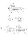
Fig. 1] Fig. 1 is a view showing a coupling structure of a fuel assembly according to a first embodiment of the present invention. - [
Fig. 2] Fig. 2 is a view showing a coupling structure of a fuel assembly according to a second embodiment of the present invention. - [
Fig. 3] Fig. 3 is a view showing a rotation prevention structure for a lock key in a coupling structure of a fuel assembly according to a third embodiment of the present invention. - [
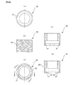
Fig. 4] Fig. 4 is a view showing an example of a structure of a latch sleeve in a coupling structure of a fuel assembly according to the present invention. - [
Fig. 5] Fig. 5 is a view showing an example of a structure of a lock key in the coupling structure of the fuel assembly according to the present invention. - [
Fig. 6] Fig. 6 is a view showing how the latch sleeve and the lock key are coupled to each other in the coupling structure of the fuel assembly according to the present invention. - [
Fig. 7] Fig. 7 is a view showing a coupling state of the upper nozzle and the latch sleeve in the coupling structure of the fuel assembly according to the present invention. - [
Fig. 8] Fig. 8 is a view showing an example in which a projecting portion of the latch sleeve is a flower shape in the coupling structure of the fuel assembly according to the present invention. - [
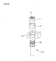
Fig. 9] Fig. 9 is a view showing a thimble plug assembly in the coupling structure of the fuel assembly according to the present invention. - [
Fig. 10] Fig. 10 is a view showing how thimble plugs are inserted, in the coupling structure of the fuel assembly according to the present invention. - [
Fig. 11] Fig. 11 is a view showing a structure of a fuel assembly of a conventional pressurized-water nuclear reactor. - [
Fig. 12] Fig. 12 is a view showing a structure where upper nozzles and latch sleeves are joined to each other in the fuel assembly of the conventional pressurized-water nuclear reactor. - [
Fig. 13] Fig. 13 is a view showing a coupling structure of a fuel assembly using a conventional nut. - Embodiments of a coupling structure of a fuel assembly according to the present invention will be described hereinafter with reference to the drawings.
Firstly, described is an example of a structure of a latch sleeve according to the coupling structure of the fuel assembly of the present invention.
InFig. 4 , parts (a) and (c) ofFig. 4 are side views of the latch sleeve; part (b) ofFig. 4 is a top view of the latch sleeve; and part (d) ofFig. 4 is a cross-sectional view of the latch sleeve taken along a cross section A-A shown in part (b) ofFig. 4 . - As shown in
Fig. 4 , alatch sleeve 10 is cylindrical, and includes a projectingportion 11 formed at an upper end portion of thelatch sleeve 10, the projectingportion 11 having a shape of a square with its corners rounded when viewed from the top. Aflange portion 12 is formed at a portion below the latchsleeve projecting portion 11. Theflange portion 12 vertically fixes thelatch sleeve 10 with a later-described upper nozzle 30 (seeFig. 6 ) or with a thick-walled pipe 40 that is inserted into theupper nozzle 30 and joined thereto by welding.
Agap portion 13 is formed between the latchsleeve projecting portion 11 and theflange portion 12. - Next, described is an example of a structure of a lock key according to the coupling structure of the fuel assembly of the present invention.
InFig. 5 , part (a) ofFig. 5 is a bottom view of the lock key; part (b) ofFig. 5 is a side view of the lock key; part (c) ofFig. 5 is a top view of the lock key; part (d) ofFig. 5 is a cross-sectional view taken along a cross section B-B shown in part (a) ofFig. 5 ; part (e) ofFig. 5 is a cross-sectional view taken along a cross section C-C shown in part (a) ofFig. 5 . - As shown in
Fig. 5 , alock key 20 is cylindrical, and includes a lockkey opening portion 21 formed at its bottom surface, the lockkey opening portion 21 having a shape of a square with its corner rounded so that the latch sleeve projecting portion 11 (seeFig. 4 ) may fit therein. Each of four sides of the lock key openingportion 21 where the wall is thick is areceiver portion 22. Amale screw thread 23 is formed on a side surface of thelock key 20. - As shown in
Fig. 7 , thelock key 20 is rotatably attached to a latchsleeve installation hole 31 of theupper nozzle 30. A structure of an inner surface of the latchsleeve installation hole 31 will be described in detail in later-described first and second embodiments. - Next, described is how the latch sleeve and the lock key are coupled to each other according to the coupling structure of the fuel assembly of the present invention.
InFig. 6 , part (a) ofFig. 6 is a view showing a state where the lock key is to be inserted onto the latch sleeve; part (b) ofFig. 6 is a view showing a state where the lock key has just been inserted onto the latch sleeve; part (c) ofFig. 6 is a view showing a state where the latch sleeve and the lock key are coupled to each other by rotating the lock key after the lock key is inserted onto the latch sleeve. - As shown in
Fig. 6 , thelatch sleeve 10 is inserted into the lockkey opening portion 21 attached to theupper nozzle 30, in a direction indicated by arrow I until the upper-nozzle fixing portion 12 of thelatch sleeve 10 contacts the bottom surface of theupper nozzle 30. Then, thelock key 20 is rotated in a direction indicated by arrow T by 45 degrees, and thereceiver portion 22 of thelock key 20 enters thegap portion 13 of thelatch sleeve 10. Here, fitting is achieved when the projectingportion 11 of thelatch sleeve 10 overlaps thereceiver portions 22 of thelock key 20, and thelatch sleeve 10 is caused not to fall from thelock key 20. Thus, thelatch sleeve 10 and theupper nozzle 30 are coupled to each other. - Moreover, the
lock key 20 may be pulled out from thelatch sleeve 10 by rotating (45 degrees in this case) thelock key 20 until there is no overlap between the projectingportion 11 of thelatch sleeve 10 and thereceiver portion 22 of thelock key 20, thereby detaching theupper nozzle 30. - Note that the projecting
portion 11 of thelatch sleeve 10 may be a triangle or a polygon shape instead of a square shown inFigs. 4 to 6 . Moreover, the projectingportion 11 formed at the upper end portion of thelatch sleeve 10 may be a flower shape or the like as shown inFig. 8 . The rotating angle of thelock key 20 required for thereceiver portion 22 of thelock key 20 to overlap the projectingportion 11 of thelatch sleeve 10 may be decided as necessary according to the shape of the projectingportion 11. InFig. 8 , part (a) ofFig. 8 is a side view of a latch sleeve with a flower-shaped projecting portion; part (b) ofFig. 8 is a top view of the latch sleeve with the flower-shaped projecting portion. - Next, described is a coupling structure of a fuel assembly according to the first embodiment of the present invention.
As shown inFig. 1 , themale screw thread 23 is formed on the side surface of thelock key 20. Afemale screw thread 32 is formed on an inner surface of the latchsleeve installation hole 31 of theupper nozzle 30. Thelock key 20 is installed inside the latchsleeve installation hole 31, and thelock key 20 and the latchsleeve installation hole 31 are screw-coupled to each other. - According to the present embodiment described above, the coupling of the
lock key 20 and the latch sleeve 10 (seeFig. 6 ) can be released and theupper nozzle 30 can thus be detached, without completely detaching the lock key 20 from the latchsleeve installation hole 31. Accordingly, there is no need to disassemble components at the time of attaching and detaching theupper nozzle 30. Thereby, a factor leading to mixing of a detached component in the fuel assembly is eliminated. - Moreover, the
lock key 20 moves up and down vertically by rotating thelock key 20 along thefemale screw thread 32 formed on the inner surface of the latchsleeve installation hole 31. This movement allows no gap to be generated between the receiver portion 22 (seeFig. 6 ) of thelock key 20 and the bottom surface of the projecting portion 11 (seeFig. 6 ) of thelatch sleeve 10. Accordingly, no vertical play can be generated at the fitting portion between thelock key 20 and thelatch sleeve 10 at the time of coupling, and a gap can be made at the fitting portion between thelock key 20 and thelatch sleeve 10 at the time of releasing the coupling. - Next, described is a coupling structure of a fuel assembly according to the second embodiment of the present invention.
Firstly, a background of the present embodiment will be described. In the above described coupling structure of the fuel assembly according to the first embodiment, when coupled to or released from thelatch sleeve 10, thelock key 20 moves up and down vertically by being rotated along thefemale screw thread 32 formed on the inner surface of the latchsleeve installation hole 31. - Accordingly, in order for the vertical play not to be generated at the time of the coupling of the
lock key 20 andlatch sleeve 10, there is a need to adjust at least a processing start position for thefemale screw thread 32 formed on the inner surface of the latchsleeve installation hole 31 of theupper nozzle 30. - Moreover, when the
upper nozzle 30 is attached as the fuel assembly, not to allow the play to be generated at the time of the coupling, the processing start position for thefemale screw thread 32 formed on the inner surface of the latchsleeve installation hole 31 of theupper nozzle 30 need to be adjusted with respect to all thelock keys 20 to be installed in theupper nozzle 30. - To solve this problem, in the present embodiment, the cylindrical thick-walled pipe 40 (see
Fig. 2 ) described later is provided for easy adjustment of the processing start position for a female screw thread on theupper nozzle 30. The present embodiment has a structure in which the thick-walled pipe 40 is installed inside thelock key 20. - As shown in
Fig. 2 , the thick-walled pipe 40 is cylindrical, and afemale screw thread 41 is formed on an inner surface of the thick-walled pipe 40. Note that the present embodiment is different from the first embodiment in that the inner surface of the latchsleeve installation hole 31 and the outer surface of the thick-walled pipe 40 are smooth surfaces, and that the thick-wall pipe 40 is rotatably installed in the latchsleeve installation hole 31 of theupper nozzle 30. - For each thickw-
walled pipe 40 installed in the corresponding latchsleeve installation hole 31 of theupper nozzle 30, a processing start position for thefemale screw thread 41 formed on the inner surface of the thick-walled pipe 40 is adjusted by adjusting an installation angle so that no vertical play is generated at the time of the coupling of thelock key 20 and thelatch sleeve 10. These thick-walled pipes 40 are joined to theupper nozzle 30 by welding or like after being adjusted of their installation angles. Thereafter, thelock keys 20 are installed inside the thick-walled pipes 40 joined to theupper nozzle 30. - [0025] According to the present embodiment described above, the following effect can be obtained in addition to the effects of the first embodiment. In the present embodiment, there is no need to consider the processing start position when forming a screw thread on the latch
sleeve installation hole 31 of theupper nozzle 30. Specifically, it is possible to optimize the processing start positions for thefemale screw threads 41 formed on the thick-walled pipes 40 only by adjusting the thick-walled pipes 40 individually so that no vertical play may be generated at the time of the coupling by the thick-walled pipe 40 and then by respectively joining the thick-walled pipes 40 andupper end portions 108 of theupper nozzle 30 by welding or like. Accordingly, no vertical play is generated at each of the coupling positions provided in theupper nozzle 30. - Next, described is a coupling structure of a fuel assembly according to a third embodiment of the present invention.
Thelock key 20 according to the above described first and second embodiments has the following problem. When thelock key 20 rotates due to some reason and becomes loose, the fitting portion between thelock key 20 and thelatch sleeve 10 may be released or the vertical play may be generated. To solve this problem, a rotation prevention structure needs to be provided for thelock key 20 to prevent the lock key 20 from rotating and becoming loose. - As the rotation prevention structure, conventional industrial methods such as caulking, pinning, and welding may be used. However, when these methods are used, quick attachment (preventing the lock key 20 from becoming loose) and detachment of the
upper nozzle 30 cannot be performed in the power station or the like. To solve this problem, in the present embodiment, a later described reel hole 60 (seeFig. 3 ) is formed at the upper end portion of thelock key 20, thereel hole 60 having a cross section other than a circle. In addition, a projecting portion 61 (seeFig. 3 ) is provided at a position in an axial direction of a later-described thimble plug 51 (seeFig. 10 ). The projectingportion 61 fits into thereel hole 60 when thethimble plug 51 is inserted. - Now, described are the thimble plugs of the coupling structure of the fuel assembly according to the third embodiment of the present invention. In a pressurized-water nuclear reactor, the thimble plugs 51 attached to a
thimble plug assembly 50 as shown inFig. 9 are inserted into thelatch sleeves 10 of theupper nozzle 30 and guidetubes 52 mechanically joined to the inside of thelatch sleeves 10 as shown inFig. 10 , respectively, thereby controlling reactor bypass flow occurring when coolant flows in theguide tubes 52. - In
Fig. 3 , part (a) ofFig. 3 is a view showing a state where the thimble plug is to be inserted into the lock key and the latch sleeve; part (b) ofFig. 3 is a cross-sectional view of the thimble plug projecting portion taken along a cross section D-D shown in part (a) ofFig. 3 ; part (c) ofFig. 3 is a top view of the lock key when viewed in a direction E-E shown in part (a) ofFig. 3 ; part (d) ofFig. 3 is a view showing a state where the thimble plug has been inserted into the lock key and the latch sleeve. - As shown in
Fig. 3 , thehexagonal reel hole 60 is formed in the upper portion of thelock key 20. If thehexagonal projecting portion 61 is formed at the position in the axial direction of thethimble plug 51, the projectingportion 61 fitting into thehexagonal reel hole 60 at the time of insertion of thethimble plug 51, the hexagonal thimbleplug projection portion 61 of the thimble plug 51 fits into thehexagonal reel hole 60 by the insertion of the thimble plug 51 into thereel hole 60. Thereby, thelock key 20 can be prevented from rotating. - As described above, the coupling structure of the fuel assembly is characterized as follows. The structure includes the thimble plugs 51 inserted into the
lock keys 20 and latchsleeves 10, respectively. In addition, thereel hole 60 having a shape other than a circle is formed on the upper portion of eachlock key 20, and the projectingportion 61 having a shape which fits into thereel hole 60 is formed on each thimble plug 51 as the thimbleplug projecting portion 61. Eachlock key 20 is prevented from rotating by fitting the thimbleplug projecting portion 61 into thereel hole 60. - Note that, although the
reel hole 60 is hexagonal in the present embodiment as an example, other configurations may be adopted. For example, thereel hole 60 may have another shape not being a circle, for example a polygon or a structure with keys on the surface. The shape of the thimbleplug projection portion 61 may be decided according to the decided shape of thereel hole 60 so that the thimbleplug projection portion 61 may fit into thereel hole 60. - As described above, according to the present embodiment, since the
projection portions 61 provided on the thimble plugs 51 fit into the reel holes 60 of thelock keys 20, thelock keys 20 are prevented from rotating only by inserting the thimble plugs 51 into thelock keys 20 and thelatch sleeves 10. - The present invention can be applied to, for example, a coupling structure between an upper nozzle and an upper end of a guide tube, of a fuel assembly used in a pressurized-water nuclear reactor.
Claims (3)
- A coupling structure of a fuel assembly including:a latch sleeve having a projecting portion formed at an upper end portion thereof;an upper nozzle having formed therein a latch sleeve installation hole into which the upper end portion of the latch sleeve is inserted; anda lock key which is installed inside the latch sleeve installation hole, and which has an opening portion formed in a bottom surface thereof, the opening portion having a shape corresponding to the projecting portion, in which the latch sleeve and the lock key are coupled to each other by rotating the lock key with the upper end portion of the latch sleeve being inserted into the lock key,the coupling structure of the fuel assembly characterized by comprising a screw coupling means for screw-coupling the lock key to the upper nozzle side with a male screw thread formed on a side surface of the lock key.
- The coupling structure of a fuel assembly according to claim 1 characterized in that the screw coupling means screw-couples the lock key and the latch sleeve installation hole with a female screw thread formed on an inner surface of the latch sleeve installation hole.
- The coupling structure of a fuel assembly according to claim 1 characterized in that
the screw coupling means includes a cylindrical thick-walled pipe installed in the latch sleeve installation hole, the thick-walled pipe having a female screw thread thread formed in an inner surface thereof, and
the screw coupling means screw-couples the lock key and the thick-walled pipe by installing the lock key in the thick-walled pipe.
Applications Claiming Priority (2)
| Application Number | Priority Date | Filing Date | Title |
|---|---|---|---|
| JP2007339284A JP4709824B2 (en) | 2007-12-28 | 2007-12-28 | Fuel assembly coupling structure |
| PCT/JP2008/072569 WO2009084402A1 (en) | 2007-12-28 | 2008-12-11 | Coupling structure of fuel assembly |
Publications (3)
| Publication Number | Publication Date |
|---|---|
| EP2196997A1 true EP2196997A1 (en) | 2010-06-16 |
| EP2196997A4 EP2196997A4 (en) | 2013-11-13 |
| EP2196997B1 EP2196997B1 (en) | 2014-08-13 |
Family
ID=40824123
Family Applications (1)
| Application Number | Title | Priority Date | Filing Date |
|---|---|---|---|
| EP08866538.5A Active EP2196997B1 (en) | 2007-12-28 | 2008-12-11 | Coupling structure for a fuel assembly |
Country Status (7)
| Country | Link |
|---|---|
| US (1) | US8964930B2 (en) |
| EP (1) | EP2196997B1 (en) |
| JP (1) | JP4709824B2 (en) |
| CN (1) | CN101681684B (en) |
| CA (1) | CA2687678C (en) |
| RU (1) | RU2412492C1 (en) |
| WO (1) | WO2009084402A1 (en) |
Families Citing this family (9)
| Publication number | Priority date | Publication date | Assignee | Title |
|---|---|---|---|---|
| RU2546648C2 (en) | 2012-10-22 | 2015-04-10 | Открытое акционерное общество "Опытное Конструкторское Бюро Машиностроения имени И.И. Африкантова" (ОАО "ОКБМ Африкантов") | Nuclear reactor fuel assembly |
| RU2534391C2 (en) * | 2013-02-19 | 2014-11-27 | Открытое акционерное общество "Машиностроительный завод" | Nuclear reactor fuel assembly |
| CN104575629B (en) * | 2014-12-05 | 2017-05-31 | 上海核工程研究设计院 | A kind of attachment structure of removable upper base and guide pipe |
| KR102642497B1 (en) * | 2015-03-03 | 2024-03-04 | 뉴스케일 파워, 엘엘씨 | Fasteners for nuclear reactor systems |
| CN106935281A (en) * | 2015-12-31 | 2017-07-07 | 中核建中核燃料元件有限公司 | A fuel assembly upper pipe seat |
| RU2627307C1 (en) * | 2016-07-15 | 2017-08-07 | Публичное акционерное общество "Машиностроительный завод" | Thermal electrical assembly of nuclear reactor |
| FR3101187B1 (en) * | 2019-09-24 | 2021-12-10 | Framatome Sa | Nuclear fuel assembly fitted with a back-up device |
| CN114215833B (en) * | 2021-11-18 | 2023-01-03 | 中国核动力研究设计院 | Guide pipe connecting structure capable of eliminating torque and uniformly bearing and fuel assembly |
| CN116580859B (en) * | 2023-06-13 | 2024-03-05 | 四川大学 | Quick detachable connection structure and method for separated fuel assembly |
Family Cites Families (13)
| Publication number | Priority date | Publication date | Assignee | Title |
|---|---|---|---|---|
| US3828868A (en) * | 1969-11-26 | 1974-08-13 | Babcock & Wilcox Co | Fuel assembly for a nuclear reactor |
| US4064004A (en) * | 1976-02-23 | 1977-12-20 | Exxon Nuclear Company, Inc. | Assembly mechanism for nuclear fuel bundles |
| JPS5912383A (en) | 1982-07-13 | 1984-01-23 | 原子燃料工業株式会社 | Nuclear fuel assembly |
| JPS5912384A (en) | 1982-07-13 | 1984-01-23 | 原子燃料工業株式会社 | Nuclear fuel assembly |
| JPS5924290A (en) * | 1982-08-02 | 1984-02-07 | 日本核燃料開発株式会社 | Nuclear fuel assembly |
| JPS59137887A (en) * | 1983-01-13 | 1984-08-08 | ウエスチングハウス エレクトリツク コ−ポレ−シヨン | Nuclear fuel assembly |
| JPS61124890A (en) | 1984-11-22 | 1986-06-12 | 原子燃料工業株式会社 | Nuclear fuel aggregate |
| JPH03238396A (en) | 1990-02-15 | 1991-10-24 | Nuclear Fuel Ind Ltd | Method for reassembling nuclear fuel assembly |
| SU1823680A1 (en) * | 1990-12-04 | 1996-06-27 | Производственное объединение "Машиностроительный завод" | Nuclear reactor fuel assembly |
| US5268948A (en) * | 1992-06-25 | 1993-12-07 | Duke Power Company | Locking assembly for nuclear fuel bundles |
| US5363423A (en) * | 1993-08-19 | 1994-11-08 | Westinghouse Electric Corporation | Quick release top nozzle assembly |
| FR2714762B1 (en) * | 1993-12-30 | 1996-03-15 | Framatome Sa | Fuel assembly of a nuclear reactor cooled by light water. |
| US5490190A (en) * | 1994-12-21 | 1996-02-06 | Westinghouse Electric Corporation | Alignment pin and method for aligning a nuclear fuel assembly with respect to a core plate disposed in a nuclear reactor pressure vessel |
-
2007
- 2007-12-28 JP JP2007339284A patent/JP4709824B2/en active Active
-
2008
- 2008-12-11 WO PCT/JP2008/072569 patent/WO2009084402A1/en not_active Ceased
- 2008-12-11 EP EP08866538.5A patent/EP2196997B1/en active Active
- 2008-12-11 RU RU2009144144/07A patent/RU2412492C1/en active
- 2008-12-11 CA CA2687678A patent/CA2687678C/en active Active
- 2008-12-11 CN CN2008800170645A patent/CN101681684B/en active Active
- 2008-12-11 US US12/601,681 patent/US8964930B2/en active Active
Also Published As
| Publication number | Publication date |
|---|---|
| CA2687678C (en) | 2013-11-26 |
| CN101681684B (en) | 2012-06-27 |
| WO2009084402A1 (en) | 2009-07-09 |
| CA2687678A1 (en) | 2009-07-09 |
| EP2196997B1 (en) | 2014-08-13 |
| JP2009162503A (en) | 2009-07-23 |
| US20100119031A1 (en) | 2010-05-13 |
| EP2196997A4 (en) | 2013-11-13 |
| CN101681684A (en) | 2010-03-24 |
| JP4709824B2 (en) | 2011-06-29 |
| US8964930B2 (en) | 2015-02-24 |
| RU2412492C1 (en) | 2011-02-20 |
Similar Documents
| Publication | Publication Date | Title |
|---|---|---|
| EP2196997B1 (en) | Coupling structure for a fuel assembly | |
| CA2854173C (en) | A formwork anchor receptacle, a formwork anchor as well as a formwork element for receiving these | |
| US7623611B2 (en) | Core spray apparatus and method for installing the same | |
| EP0730775B1 (en) | Fuel assembly with guide thimbles including locking elements for a nuclear reactor | |
| US6421406B1 (en) | Core spray upper T-box to safe end attachment | |
| US20090001229A1 (en) | Apparatus and method for repairing riser pipe elbow weld in boiling water nuclear reactor | |
| JP6283154B2 (en) | Method and apparatus for extended split bushpipe | |
| US9847146B2 (en) | Anti-seismic apparatus for control element drive mechanisms | |
| JP2008525740A (en) | Sanitary drain valve | |
| KR20110093167A (en) | Ship | |
| CN210307631U (en) | Reactor pressure vessel top cap dismouting guider | |
| EP4439635A1 (en) | Semiconductor gas pipe fitting fastener | |
| CN220651663U (en) | Fuel assembly and connecting structure of tube seat and guide tube thereof | |
| CN209001520U (en) | A kind of mortise and tenon type preheating embedding line connector | |
| KR20120129207A (en) | Flange for connecting pipe | |
| EP3705636B1 (en) | Wall mountable sanitary plumbing device with integral valve | |
| JP2004037379A (en) | Peripheral fuel support and its assembly method | |
| JP4306930B2 (en) | Joint for segment, segment provided with the joint, segment connecting method, and connecting member used for the joint for segment | |
| WO2026103463A1 (en) | Nuclear fuel mechanism and assembly method therefor | |
| JP6594035B2 (en) | Multiple division type guide pin and structure installation method | |
| CN105090645B (en) | Water pan joint structure and water pan assembly | |
| JP2005054415A (en) | Nut retainer of bolt connection type lid body | |
| JPH09281276A (en) | Boiling water reactor shroud head bolts | |
| JP2012117820A (en) | Stud bolt for fixing core support plate, and installing method of core support plate |
Legal Events
| Date | Code | Title | Description |
|---|---|---|---|
| PUAI | Public reference made under article 153(3) epc to a published international application that has entered the european phase |
Free format text: ORIGINAL CODE: 0009012 |
|
| 17P | Request for examination filed |
Effective date: 20091119 |
|
| AK | Designated contracting states |
Kind code of ref document: A1 Designated state(s): AT BE BG CH CY CZ DE DK EE ES FI FR GB GR HR HU IE IS IT LI LT LU LV MC MT NL NO PL PT RO SE SI SK TR |
|
| AX | Request for extension of the european patent |
Extension state: AL BA MK RS |
|
| DAX | Request for extension of the european patent (deleted) | ||
| A4 | Supplementary search report drawn up and despatched |
Effective date: 20131016 |
|
| RIC1 | Information provided on ipc code assigned before grant |
Ipc: G21C 3/33 20060101AFI20131010BHEP Ipc: G21C 3/334 20060101ALI20131010BHEP |
|
| GRAP | Despatch of communication of intention to grant a patent |
Free format text: ORIGINAL CODE: EPIDOSNIGR1 |
|
| RIC1 | Information provided on ipc code assigned before grant |
Ipc: G21C 3/334 20060101ALI20140217BHEP Ipc: G21C 3/33 20060101AFI20140217BHEP |
|
| INTG | Intention to grant announced |
Effective date: 20140314 |
|
| GRAS | Grant fee paid |
Free format text: ORIGINAL CODE: EPIDOSNIGR3 |
|
| GRAA | (expected) grant |
Free format text: ORIGINAL CODE: 0009210 |
|
| AK | Designated contracting states |
Kind code of ref document: B1 Designated state(s): AT BE BG CH CY CZ DE DK EE ES FI FR GB GR HR HU IE IS IT LI LT LU LV MC MT NL NO PL PT RO SE SI SK TR |
|
| REG | Reference to a national code |
Ref country code: GB Ref legal event code: FG4D |
|
| REG | Reference to a national code |
Ref country code: CH Ref legal event code: EP Ref country code: AT Ref legal event code: REF Ref document number: 682636 Country of ref document: AT Kind code of ref document: T Effective date: 20140815 |
|
| REG | Reference to a national code |
Ref country code: IE Ref legal event code: FG4D |
|
| REG | Reference to a national code |
Ref country code: DE Ref legal event code: R096 Ref document number: 602008033892 Country of ref document: DE Effective date: 20140925 |
|
| REG | Reference to a national code |
Ref country code: NL Ref legal event code: VDEP Effective date: 20140813 |
|
| REG | Reference to a national code |
Ref country code: AT Ref legal event code: MK05 Ref document number: 682636 Country of ref document: AT Kind code of ref document: T Effective date: 20140813 |
|
| REG | Reference to a national code |
Ref country code: LT Ref legal event code: MG4D |
|
| PG25 | Lapsed in a contracting state [announced via postgrant information from national office to epo] |
Ref country code: BG Free format text: LAPSE BECAUSE OF FAILURE TO SUBMIT A TRANSLATION OF THE DESCRIPTION OR TO PAY THE FEE WITHIN THE PRESCRIBED TIME-LIMIT Effective date: 20141113 Ref country code: FI Free format text: LAPSE BECAUSE OF FAILURE TO SUBMIT A TRANSLATION OF THE DESCRIPTION OR TO PAY THE FEE WITHIN THE PRESCRIBED TIME-LIMIT Effective date: 20140813 Ref country code: LT Free format text: LAPSE BECAUSE OF FAILURE TO SUBMIT A TRANSLATION OF THE DESCRIPTION OR TO PAY THE FEE WITHIN THE PRESCRIBED TIME-LIMIT Effective date: 20140813 Ref country code: NO Free format text: LAPSE BECAUSE OF FAILURE TO SUBMIT A TRANSLATION OF THE DESCRIPTION OR TO PAY THE FEE WITHIN THE PRESCRIBED TIME-LIMIT Effective date: 20141113 Ref country code: SE Free format text: LAPSE BECAUSE OF FAILURE TO SUBMIT A TRANSLATION OF THE DESCRIPTION OR TO PAY THE FEE WITHIN THE PRESCRIBED TIME-LIMIT Effective date: 20140813 Ref country code: ES Free format text: LAPSE BECAUSE OF FAILURE TO SUBMIT A TRANSLATION OF THE DESCRIPTION OR TO PAY THE FEE WITHIN THE PRESCRIBED TIME-LIMIT Effective date: 20140813 Ref country code: PT Free format text: LAPSE BECAUSE OF FAILURE TO SUBMIT A TRANSLATION OF THE DESCRIPTION OR TO PAY THE FEE WITHIN THE PRESCRIBED TIME-LIMIT Effective date: 20141215 Ref country code: GR Free format text: LAPSE BECAUSE OF FAILURE TO SUBMIT A TRANSLATION OF THE DESCRIPTION OR TO PAY THE FEE WITHIN THE PRESCRIBED TIME-LIMIT Effective date: 20141114 |
|
| PG25 | Lapsed in a contracting state [announced via postgrant information from national office to epo] |
Ref country code: HR Free format text: LAPSE BECAUSE OF FAILURE TO SUBMIT A TRANSLATION OF THE DESCRIPTION OR TO PAY THE FEE WITHIN THE PRESCRIBED TIME-LIMIT Effective date: 20140813 Ref country code: AT Free format text: LAPSE BECAUSE OF FAILURE TO SUBMIT A TRANSLATION OF THE DESCRIPTION OR TO PAY THE FEE WITHIN THE PRESCRIBED TIME-LIMIT Effective date: 20140813 Ref country code: LV Free format text: LAPSE BECAUSE OF FAILURE TO SUBMIT A TRANSLATION OF THE DESCRIPTION OR TO PAY THE FEE WITHIN THE PRESCRIBED TIME-LIMIT Effective date: 20140813 Ref country code: CY Free format text: LAPSE BECAUSE OF FAILURE TO SUBMIT A TRANSLATION OF THE DESCRIPTION OR TO PAY THE FEE WITHIN THE PRESCRIBED TIME-LIMIT Effective date: 20140813 Ref country code: IS Free format text: LAPSE BECAUSE OF FAILURE TO SUBMIT A TRANSLATION OF THE DESCRIPTION OR TO PAY THE FEE WITHIN THE PRESCRIBED TIME-LIMIT Effective date: 20141213 |
|
| PG25 | Lapsed in a contracting state [announced via postgrant information from national office to epo] |
Ref country code: NL Free format text: LAPSE BECAUSE OF FAILURE TO SUBMIT A TRANSLATION OF THE DESCRIPTION OR TO PAY THE FEE WITHIN THE PRESCRIBED TIME-LIMIT Effective date: 20140813 |
|
| PG25 | Lapsed in a contracting state [announced via postgrant information from national office to epo] |
Ref country code: EE Free format text: LAPSE BECAUSE OF FAILURE TO SUBMIT A TRANSLATION OF THE DESCRIPTION OR TO PAY THE FEE WITHIN THE PRESCRIBED TIME-LIMIT Effective date: 20140813 Ref country code: IT Free format text: LAPSE BECAUSE OF FAILURE TO SUBMIT A TRANSLATION OF THE DESCRIPTION OR TO PAY THE FEE WITHIN THE PRESCRIBED TIME-LIMIT Effective date: 20140813 Ref country code: CZ Free format text: LAPSE BECAUSE OF FAILURE TO SUBMIT A TRANSLATION OF THE DESCRIPTION OR TO PAY THE FEE WITHIN THE PRESCRIBED TIME-LIMIT Effective date: 20140813 Ref country code: DK Free format text: LAPSE BECAUSE OF FAILURE TO SUBMIT A TRANSLATION OF THE DESCRIPTION OR TO PAY THE FEE WITHIN THE PRESCRIBED TIME-LIMIT Effective date: 20140813 Ref country code: RO Free format text: LAPSE BECAUSE OF FAILURE TO SUBMIT A TRANSLATION OF THE DESCRIPTION OR TO PAY THE FEE WITHIN THE PRESCRIBED TIME-LIMIT Effective date: 20140813 Ref country code: SK Free format text: LAPSE BECAUSE OF FAILURE TO SUBMIT A TRANSLATION OF THE DESCRIPTION OR TO PAY THE FEE WITHIN THE PRESCRIBED TIME-LIMIT Effective date: 20140813 |
|
| REG | Reference to a national code |
Ref country code: DE Ref legal event code: R097 Ref document number: 602008033892 Country of ref document: DE |
|
| PG25 | Lapsed in a contracting state [announced via postgrant information from national office to epo] |
Ref country code: PL Free format text: LAPSE BECAUSE OF FAILURE TO SUBMIT A TRANSLATION OF THE DESCRIPTION OR TO PAY THE FEE WITHIN THE PRESCRIBED TIME-LIMIT Effective date: 20140813 |
|
| PLBE | No opposition filed within time limit |
Free format text: ORIGINAL CODE: 0009261 |
|
| STAA | Information on the status of an ep patent application or granted ep patent |
Free format text: STATUS: NO OPPOSITION FILED WITHIN TIME LIMIT |
|
| PG25 | Lapsed in a contracting state [announced via postgrant information from national office to epo] |
Ref country code: BE Free format text: LAPSE BECAUSE OF NON-PAYMENT OF DUE FEES Effective date: 20141231 |
|
| REG | Reference to a national code |
Ref country code: DE Ref legal event code: R119 Ref document number: 602008033892 Country of ref document: DE |
|
| 26N | No opposition filed |
Effective date: 20150515 |
|
| PG25 | Lapsed in a contracting state [announced via postgrant information from national office to epo] |
Ref country code: LU Free format text: LAPSE BECAUSE OF FAILURE TO SUBMIT A TRANSLATION OF THE DESCRIPTION OR TO PAY THE FEE WITHIN THE PRESCRIBED TIME-LIMIT Effective date: 20141211 |
|
| REG | Reference to a national code |
Ref country code: CH Ref legal event code: PL |
|
| GBPC | Gb: european patent ceased through non-payment of renewal fee |
Effective date: 20141211 |
|
| REG | Reference to a national code |
Ref country code: IE Ref legal event code: MM4A |
|
| PG25 | Lapsed in a contracting state [announced via postgrant information from national office to epo] |
Ref country code: LI Free format text: LAPSE BECAUSE OF NON-PAYMENT OF DUE FEES Effective date: 20141231 Ref country code: CH Free format text: LAPSE BECAUSE OF NON-PAYMENT OF DUE FEES Effective date: 20141231 Ref country code: IE Free format text: LAPSE BECAUSE OF NON-PAYMENT OF DUE FEES Effective date: 20141211 Ref country code: GB Free format text: LAPSE BECAUSE OF NON-PAYMENT OF DUE FEES Effective date: 20141211 Ref country code: DE Free format text: LAPSE BECAUSE OF NON-PAYMENT OF DUE FEES Effective date: 20150701 |
|
| REG | Reference to a national code |
Ref country code: FR Ref legal event code: PLFP Year of fee payment: 8 |
|
| PG25 | Lapsed in a contracting state [announced via postgrant information from national office to epo] |
Ref country code: SI Free format text: LAPSE BECAUSE OF FAILURE TO SUBMIT A TRANSLATION OF THE DESCRIPTION OR TO PAY THE FEE WITHIN THE PRESCRIBED TIME-LIMIT Effective date: 20140813 |
|
| PG25 | Lapsed in a contracting state [announced via postgrant information from national office to epo] |
Ref country code: MC Free format text: LAPSE BECAUSE OF FAILURE TO SUBMIT A TRANSLATION OF THE DESCRIPTION OR TO PAY THE FEE WITHIN THE PRESCRIBED TIME-LIMIT Effective date: 20140813 |
|
| PG25 | Lapsed in a contracting state [announced via postgrant information from national office to epo] |
Ref country code: MT Free format text: LAPSE BECAUSE OF FAILURE TO SUBMIT A TRANSLATION OF THE DESCRIPTION OR TO PAY THE FEE WITHIN THE PRESCRIBED TIME-LIMIT Effective date: 20140813 Ref country code: BE Free format text: LAPSE BECAUSE OF FAILURE TO SUBMIT A TRANSLATION OF THE DESCRIPTION OR TO PAY THE FEE WITHIN THE PRESCRIBED TIME-LIMIT Effective date: 20140813 Ref country code: HU Free format text: LAPSE BECAUSE OF FAILURE TO SUBMIT A TRANSLATION OF THE DESCRIPTION OR TO PAY THE FEE WITHIN THE PRESCRIBED TIME-LIMIT; INVALID AB INITIO Effective date: 20081211 Ref country code: TR Free format text: LAPSE BECAUSE OF FAILURE TO SUBMIT A TRANSLATION OF THE DESCRIPTION OR TO PAY THE FEE WITHIN THE PRESCRIBED TIME-LIMIT Effective date: 20140813 |
|
| REG | Reference to a national code |
Ref country code: FR Ref legal event code: PLFP Year of fee payment: 9 |
|
| REG | Reference to a national code |
Ref country code: FR Ref legal event code: PLFP Year of fee payment: 10 |
|
| P01 | Opt-out of the competence of the unified patent court (upc) registered |
Effective date: 20230522 |
|
| PGFP | Annual fee paid to national office [announced via postgrant information from national office to epo] |
Ref country code: FR Payment date: 20251110 Year of fee payment: 18 |