EP2196882A2 - Robot system - Google Patents
Robot system Download PDFInfo
- Publication number
- EP2196882A2 EP2196882A2 EP09168274A EP09168274A EP2196882A2 EP 2196882 A2 EP2196882 A2 EP 2196882A2 EP 09168274 A EP09168274 A EP 09168274A EP 09168274 A EP09168274 A EP 09168274A EP 2196882 A2 EP2196882 A2 EP 2196882A2
- Authority
- EP
- European Patent Office
- Prior art keywords
- robot
- change
- robots
- setting screen
- control device
- Prior art date
- Legal status (The legal status is an assumption and is not a legal conclusion. Google has not performed a legal analysis and makes no representation as to the accuracy of the status listed.)
- Withdrawn
Links
Images



Classifications
-
- G—PHYSICS
- G05—CONTROLLING; REGULATING
- G05B—CONTROL OR REGULATING SYSTEMS IN GENERAL; FUNCTIONAL ELEMENTS OF SUCH SYSTEMS; MONITORING OR TESTING ARRANGEMENTS FOR SUCH SYSTEMS OR ELEMENTS
- G05B19/00—Program-control systems
- G05B19/02—Program-control systems electric
- G05B19/18—Numerical control [NC], i.e. automatically operating machines, in particular machine tools, e.g. in a manufacturing environment, so as to execute positioning, movement or co-ordinated operations by means of program data in numerical form
- G05B19/409—Numerical control [NC], i.e. automatically operating machines, in particular machine tools, e.g. in a manufacturing environment, so as to execute positioning, movement or co-ordinated operations by means of program data in numerical form characterised by using manual data input [MDI] or by using control panel, e.g. controlling functions with the panel; characterised by control panel details or by setting parameters
-
- G—PHYSICS
- G05—CONTROLLING; REGULATING
- G05B—CONTROL OR REGULATING SYSTEMS IN GENERAL; FUNCTIONAL ELEMENTS OF SUCH SYSTEMS; MONITORING OR TESTING ARRANGEMENTS FOR SUCH SYSTEMS OR ELEMENTS
- G05B2219/00—Program-control systems
- G05B2219/20—Pc systems
- G05B2219/23—Pc programming
- G05B2219/23132—Multifunction display
-
- G—PHYSICS
- G05—CONTROLLING; REGULATING
- G05B—CONTROL OR REGULATING SYSTEMS IN GENERAL; FUNCTIONAL ELEMENTS OF SUCH SYSTEMS; MONITORING OR TESTING ARRANGEMENTS FOR SUCH SYSTEMS OR ELEMENTS
- G05B2219/00—Program-control systems
- G05B2219/20—Pc systems
- G05B2219/23—Pc programming
- G05B2219/23135—Display to console, panel which sends parameters, commands
-
- G—PHYSICS
- G05—CONTROLLING; REGULATING
- G05B—CONTROL OR REGULATING SYSTEMS IN GENERAL; FUNCTIONAL ELEMENTS OF SUCH SYSTEMS; MONITORING OR TESTING ARRANGEMENTS FOR SUCH SYSTEMS OR ELEMENTS
- G05B2219/00—Program-control systems
- G05B2219/30—Nc systems
- G05B2219/36—Nc in input of data, input key till input tape
- G05B2219/36168—Touchscreen
-
- G—PHYSICS
- G05—CONTROLLING; REGULATING
- G05B—CONTROL OR REGULATING SYSTEMS IN GENERAL; FUNCTIONAL ELEMENTS OF SUCH SYSTEMS; MONITORING OR TESTING ARRANGEMENTS FOR SUCH SYSTEMS OR ELEMENTS
- G05B2219/00—Program-control systems
- G05B2219/30—Nc systems
- G05B2219/39—Robotics, robotics to robotics hand
- G05B2219/39136—Teach each manipulator independently or dependently from each other
-
- G—PHYSICS
- G05—CONTROLLING; REGULATING
- G05B—CONTROL OR REGULATING SYSTEMS IN GENERAL; FUNCTIONAL ELEMENTS OF SUCH SYSTEMS; MONITORING OR TESTING ARRANGEMENTS FOR SUCH SYSTEMS OR ELEMENTS
- G05B2219/00—Program-control systems
- G05B2219/30—Nc systems
- G05B2219/39—Robotics, robotics to robotics hand
- G05B2219/39448—Same teach pendant connects to many robot controllers over network
Definitions
- the present invention relates to a robot system in which a robot carries out operation.
- a robot system in the related art includes a robot having a plurality of joints (multi-joint robot), a robot control device configured to control the robot, and a robot teaching device connected to the robot control device and configured to teach and operate the multi-joint robot.
- the robot teaching device has a display device for displaying and editing an operation program of the robot and various kinds of parameters. Such displayed data can be operated and edited on the screen of the display device.
- the robot control device supplies data stored in a memory included therein to the robot teaching device.
- the robot teaching device displays the data on the display device.
- a robot system includes a plurality of robots and external axes (called a control group hereafter) connected to a robot control device and is operated by one robot teaching device
- a control group hereafter
- one of the robots to be operated needs to be selected and changed by a key operation and a touch panel operation on the robot teaching device.
- the present invention provides a robot system including a robot teaching device that operates an object to be operated even in a case where one robot teaching device operates a plurality of control groups.
- a robot system includes a plurality of robots each having a plurality of joints, a robot control device connected to the plurality of robots and a robot teaching device configured to communicate with the robot control device so as to teach and operate the robots.
- the robot control device automatically selects one of the robots to be operated in accordance with a change in a display state of a display of the robot teaching device.
- Fig. 1 is a block diagram of a robot system according to an embodiment of the present invention
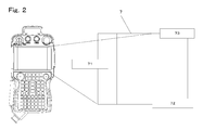
- Fig. 2 is a diagram of a display according to an embodiment of the present invention.
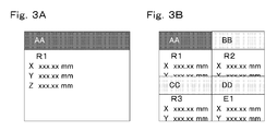
- Fig. 3A shows an all-purpose area in an undivided mode according to an embodiment of the present invention
- the robot control device 1 includes a control unit 2 configured to control the whole operation of the system, a communication unit 3 configured to communicate with the robot teaching device 6, and a drive unit 4 configured to supply power necessary for operating the robots.
- a message for attracting the operator's attention or explaining operation conditions is displayed in accordance with the condition of the robot teaching device 6. If, for example, the operator tries to put the robot into operation without turning on the servo power supply of the control group, a message such as "turn power supply on” is displayed.
- the screen of the function selected from the list of the functions of the category that the operator has selected in the menu area 71 is displayed.
- the all-purpose area 73 is displayed in an undivided mode, i.e., not divided into sub-areas.
- the all-purpose area 73 is displayed in a divided mode, i.e., divided into sub-areas.
- This menu provides patterns of dividing the all-purpose area 73 into a plurality of sub-areas. If the operator selects a preferred pattern, the all-purpose area 73 is divided in accordance with the selected pattern.
- the screens of the "AA” to “DD” settings are displayed in the respective four sub-areas shown in the all-purpose area 73.
- the "AA” setting is a screen for setting the origin of each of the control groups.
- the "BB” setting is a screen for displaying a current position of each of the control groups.
- the "CC” setting is a screen for displaying control parameters such as a velocity gain, a position gain and so on of each of the control groups.
- the "DD” setting is a screen for displaying operation parameters such as inertia, a weight and so on of each of the control groups.
- the "AA” setting is the active screen by default. A change in a value included in the "AA” setting will be explained.
- the position of the origin of a robot 1 is shown in the screen of the "AA” setting. As the screen of the "AA” setting is the active screen, the position of the origin can be changed.
- the operator presses a page change key of the robot teaching device 6 shown in Fig. 1 or selects an operation key shown in the all-purpose area 73 shown in Fig. 2 . Then, the position of the origin of the robot 2 can be changed. If the position of the origin of the robot 2 is shown, the position of the origin can be changed. As described above, the operator can change an object to be operated and a value shown in the active screen using the page change key or the operation key.
- a signal of the key is sent to the control unit 2 of the robot control device 1 via the communication units 3 and 8 shown in Fig. 1 .
- the robot teaching device 6 detects which portion has been touched in the all-purpose area 73, determines which one of the screens shown in the divided sub-areas has been requested in accordance with the coordinates of the touched portion, and notifies the robot control device 1 of the determined result.
- the control unit 2 of the robot control device 1 detects the state of the active change of the robot teaching device 6, and gives corresponding portions instructions. If an active change is requested, the control unit 2 of the robot control device 1 supplies an instruction to an all-purpose area display processing unit included in the control unit 2 and configured to perform a display control process of the all-purpose area 73. Upon receiving the above instructions, the all-purpose area display processing unit changes the active screen.
- the robot teaching device 6 requests the robot control device 1 to change the active screen, and the control unit 2 compares the display states of the current and next active screens with each other. After the control unit 2 sets a flag for requesting a control group change as necessary, the all-purpose area display processing unit performs the active screen change process. After the active screen change process is performed, the active screen is changed to the new one that has been requested.
Landscapes
- Engineering & Computer Science (AREA)
- Human Computer Interaction (AREA)
- Manufacturing & Machinery (AREA)
- Physics & Mathematics (AREA)
- General Physics & Mathematics (AREA)
- Automation & Control Theory (AREA)
- Manipulator (AREA)
- Numerical Control (AREA)
Abstract
Description
- The present application is related to Japanese Patent application no.
2008-293278 - The present invention relates to a robot system in which a robot carries out operation.
- A robot system in the related art includes a robot having a plurality of joints (multi-joint robot), a robot control device configured to control the robot, and a robot teaching device connected to the robot control device and configured to teach and operate the multi-joint robot. Among the above devices, the robot teaching device has a display device for displaying and editing an operation program of the robot and various kinds of parameters. Such displayed data can be operated and edited on the screen of the display device.
- The robot control device supplies data stored in a memory included therein to the robot teaching device. The robot teaching device displays the data on the display device.
- Such a robot teaching device is disclosed, for example, in Japanese Unexamined Patent Application Publication No.
2005-219196 07-276274 - In a case where a robot system includes a plurality of robots and external axes (called a control group hereafter) connected to a robot control device and is operated by one robot teaching device, one of the robots to be operated needs to be selected and changed by a key operation and a touch panel operation on the robot teaching device.
- A screen displayed on the display device of the robot teaching device needs to have a function of automatically changing the robot to be operated according to displayed content.
- In robot systems of the related art, there is such a case that the control of one robot is only taken into account or the robot system including only one robot teaching device is not taken into account. Moreover, a case where a plurality of screens is displayed is not taken into account. In such cases, a control group associated with a screen by an operator may possibly be different from a control group to be operated by the robot control device. Thus, if the operator operates a control group, a problem may occur that a control group that the operator does not intend to operate works and the intended control group does not work.
- Accordingly, the present invention provides a robot system including a robot teaching device that operates an object to be operated even in a case where one robot teaching device operates a plurality of control groups.
- According to one aspect of the present invention, a robot system includes a plurality of robots each having a plurality of joints, a robot control device connected to the plurality of robots and a robot teaching device configured to communicate with the robot control device so as to teach and operate the robots. The robot control device automatically selects one of the robots to be operated in accordance with a change in a display state of a display of the robot teaching device.
- A more complete appreciation of the invention and many of the attendant advantages thereof will be readily obtained as the same becomes better understood by reference to the following detailed description when considered in connection with the accompanying drawings, wherein:
-
Fig. 1 is a block diagram of a robot system according to an embodiment of the present invention; -
Fig. 2 is a diagram of a display according to an embodiment of the present invention; -
Fig. 3A shows an all-purpose area in an undivided mode according to an embodiment of the present invention; -
Fig. 3B shows an all-purpose area in a divided mode according to an embodiment of the present invention; -
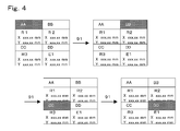
Fig. 4 illustrates a method for an active change using a keypad according to an embodiment of the present invention; -
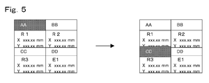
Fig. 5 illustrates a method for an active change using a touch panel according to an embodiment of the present invention; -
Fig. 6 is a flowchart illustrating processing of an all-purpose area display processing unit according to an embodiment of the present invention; and -
Fig. 7 is a flowchart of a new active screen according to an embodiment of the present invention. - Embodiments will now be described with reference to the accompanying drawings, wherein like reference numerals designate corresponding or identical elements throughout the various drawings.
-
Fig. 1 shows a block diagram of an embodiment of the present invention. InFig. 1 , arobot control device 1 is connected to a robot teaching device 6 through a communication cable. Meanwhile, a plurality of control groups 5, each of which includes a plurality of robots R and a plurality of external axes E, is connected to therobot control device 1 through other cables. - The
robot control device 1 includes acontrol unit 2 configured to control the whole operation of the system, acommunication unit 3 configured to communicate with the robot teaching device 6, and adrive unit 4 configured to supply power necessary for operating the robots. - The robot teaching device 6 includes a
communication unit 8 configured to communicate with therobot control device 1, adisplay 7 having a touch panel function for displaying various kinds of data, and akeypad 9 for key operations. - The
robot control device 1 and the robot teaching device 6 communicate with each other through thecommunication units robot control device 1 and the robot teaching device 6, respectively. Therobot control device 1 produces data to be displayed on a screen of thedisplay 7 and supplies the data to the robot teaching device 6 via thecommunication units keypad 9 of the robot teaching device 6 is pressed, the robot teaching device 6 informs therobot control device 1 which key has been pressed. If the touch panel is operated, the robot teaching device 6 detects which portion has been touched on the screen and supplies an operation request corresponding to the touched portion to therobot control device 1. -
Fig. 2 shows an example of classification of areas displayed on thedisplay 7 of the robot teaching device 6. The content displayed on thedisplay 7 is composed of three areas, which are amenu area 71, amessage area 72 and an all-purpose area 73. In themenu area 71, functions such as a robot operation, a working menu, a system setting and a screen setting necessary for teaching a robot are classified and displayed according to the respective categories. If the operator selects one of the categories, a list of functions belonging to that category is displayed in themenu area 71. If the operator selects one of the functions that the operator wants to display, a screen corresponding to that function is displayed in the all-purpose area 73. - In the
message area 72, a message for attracting the operator's attention or explaining operation conditions is displayed in accordance with the condition of the robot teaching device 6. If, for example, the operator tries to put the robot into operation without turning on the servo power supply of the control group, a message such as "turn power supply on" is displayed. - In the all-
purpose area 73, the screen of the function selected from the list of the functions of the category that the operator has selected in themenu area 71 is displayed. As usual, as shown inFig. 3A , the all-purpose area 73 is displayed in an undivided mode, i.e., not divided into sub-areas. If the operator selects a menu for dividing the screen from the functions of the screen-setting category in themenu area 71, the all-purpose area 73 is displayed in a divided mode, i.e., divided into sub-areas. This menu provides patterns of dividing the all-purpose area 73 into a plurality of sub-areas. If the operator selects a preferred pattern, the all-purpose area 73 is divided in accordance with the selected pattern. If the operator selects a menu, screens that the operator prefers are independently displayed in the respective sub-areas of the all-purpose area 73. The operator selects a screen that the operator wants to edit in the divided all-purpose area 73. A method for selecting the screen is pressing an activescreen change key 91 included in thekeypad 9 of the robot teaching device 6 shown inFig. 1 so as to change an active screen to be edited in such a manner that the active screen changes from "AA" setting to "BB" setting, "CC" setting and then "DD" setting in order as shown inFig. 4 . Another method for selecting the screen is touching and directly designating the sub-area of the all-purpose area 73 in which the screen to be edited is displayed in such a manner that the active screen changes from the "AA" setting to the "CC" setting as shown inFig. 5 . The screen selected using each of the above methods is highlighted compared with other screens (hereafter, the selected screen and the other screens are called the active screen and non-active screens, respectively. The operation of changing the active screen using the active screen change key or the touch panel is called the active change). - As shown in
Fig. 5 , the screens of the "AA" to "DD" settings are displayed in the respective four sub-areas shown in the all-purpose area 73. For example, the "AA" setting is a screen for setting the origin of each of the control groups. The "BB" setting is a screen for displaying a current position of each of the control groups. The "CC" setting is a screen for displaying control parameters such as a velocity gain, a position gain and so on of each of the control groups. The "DD" setting is a screen for displaying operation parameters such as inertia, a weight and so on of each of the control groups. - The "AA" setting is the active screen by default. A change in a value included in the "AA" setting will be explained. The position of the origin of a
robot 1 is shown in the screen of the "AA" setting. As the screen of the "AA" setting is the active screen, the position of the origin can be changed. In order to change the position of the origin of arobot 2, the operator presses a page change key of the robot teaching device 6 shown inFig. 1 or selects an operation key shown in the all-purpose area 73 shown inFig. 2 . Then, the position of the origin of therobot 2 can be changed. If the position of the origin of therobot 2 is shown, the position of the origin can be changed. As described above, the operator can change an object to be operated and a value shown in the active screen using the page change key or the operation key. - The screen of the "BB", "CC" or the "DD" setting can be made the active screen similar to the screen of the "AA" setting as described above, and the operator can change an object to be operated and a value shown in the active screen using the page change key or the operation key.
- A relation between the active screen change process and an operation of the
control unit 2 of therobot control device 1 will be explained with reference toFig. 6 . - If an operator performs an active change using the active
screen change key 91, a signal of the key is sent to thecontrol unit 2 of therobot control device 1 via thecommunication units Fig. 1 . If the operator performs an active change using the touch panel, the robot teaching device 6 detects which portion has been touched in the all-purpose area 73, determines which one of the screens shown in the divided sub-areas has been requested in accordance with the coordinates of the touched portion, and notifies therobot control device 1 of the determined result. - The
control unit 2 of therobot control device 1 detects the state of the active change of the robot teaching device 6, and gives corresponding portions instructions. If an active change is requested, thecontrol unit 2 of therobot control device 1 supplies an instruction to an all-purpose area display processing unit included in thecontrol unit 2 and configured to perform a display control process of the all-purpose area 73. Upon receiving the above instructions, the all-purpose area display processing unit changes the active screen. - In order to perform an active change, the
control unit 2 obtains information with respect to the current active screen and which one of the control groups 5 should be selected for the next screen, i.e., content of the screen set to be active next, for a control processing unit of each of the two screens. That is, for example, a case where the current active screen shows a setting of therobot 1 and the screen set to be active next shows a setting of therobot 2. - If the provided settings of the control groups for the two screens are compared with each other and are different from each other, the control group 5 needs to be changed to the one to be selected on the new active screen. Thus, the
control unit 2 sets a flag for requesting a control group change in a process program in the control processing unit. - As described above, the robot teaching device 6 requests the
robot control device 1 to change the active screen, and thecontrol unit 2 compares the display states of the current and next active screens with each other. After thecontrol unit 2 sets a flag for requesting a control group change as necessary, the all-purpose area display processing unit performs the active screen change process. After the active screen change process is performed, the active screen is changed to the new one that has been requested. - Upon the active screen being changed to the new one, the
control unit 2 of therobot control device 1 detects a state of the flag for requesting a control group change. If the flag is set, thecontrol unit 2 requests the control processing unit that controls the operation of the new active screen to change the control group. Upon being requested, the control processing unit determines which one of the control groups the current control group should be changed to on the basis the data that the control processing unit displays at the moment, and changes the control group as shown inFig. 7 . - Although the control group 5 may be determined for a screen depending on the state of the screen, a screen for displaying data unrelated to the control group 5 may not uniquely determine which one of the control groups 5 should be selected as an object to be operated. If the control group 5 cannot be changed when such a screen is an active screen, the control group 5 to be operated varies depending on an order of the active screen change, which causes a safety problem. Accordingly, if the active screen is changed, using any of the above methods, the state of selecting the control group 5 returns to the initial state once. As a result, if the active screen is unrelated to the control group 5, the state of selecting the control group 5 can be unified to the initial state. Thus, if a control group change is requested after the control group 5 to be operated is initialized, the control group 5 can be properly changed only on a screen related to the control group 5.
Claims (8)
- A robot system, comprising:a plurality of robots each having a plurality of joints;a robot teaching device having a display, the robot teaching device being configured to teach and operate the robots; anda robot control device connected to the robots and the robot teaching device, the robot control device being configured to control the robots, the robot control device being configured to automatically select one of the robots to be operated in accordance with a change in a display state of the display.
- The robot system according to Claim 1, wherein the display state of the display is formed of a menu area, a message area and an all-purpose area.
- The robot system according to Claim 1 or 2, wherein the display state of the display includes a menu area and an all-purpose area adapted for displaying a setting screen selected in the menu area, the setting screen being undivided or divided into a plurality of sub-areas in accordance with an operation in the menu area.
- The robot system according to any one of Claims 1 to 3, wherein the display state of the display includes a menu area and an all-purpose area adapted for displaying a setting screen selected in the menu area, the setting screen including data of the robots, the setting screen being changeable.
- The robot system according to any one of Claims 1 to 4, wherein the display state of the display includes a menu area and an all-purpose area adapted for displaying a setting screen selected in the menu area, the setting screen being divided into a plurality of sub-areas, the robot teaching device being configured to be operated either by using a change key of the robot teaching device or by touching a screen of the all-purpose area so as to change one of the sub-areas to an active state.
- The robot system according to any one of Claims 1 to 5, wherein the display state of the display includes a menu area and an all-purpose area adapted for displaying a setting screen selected in the menu area, the setting screen being divided into a plurality of sub-areas, the robot control device being informed of a change of the setting screen upon one of the sub-areas being changed to an active state, the robot control device being configured to cause a control program to recognize the change upon being informed by the robot teaching device.
- The robot system according to any one of Claims 1 to 6, wherein the display state of the display includes a menu area and an all-purpose area adapted for displaying a setting screen selected in the menu area, the setting screen being divided into a plurality of sub-areas, the robot teaching device being configured to inform the robot control device of a change of the setting screen upon one of the sub-areas being changed to an active state, the robot control device being configured to cause a control program to recognize the change, the robot teaching device being further configured to provide the robot control device with setting content of the setting screen, the robot control device being configured to compare the setting screen before the change of the active state and the setting screen after the change of the active state so as to change the setting content.
- A robot system, comprising:a plurality of robots each having a plurality of joints;a plurality of external axes configured to work in cooperation with the robots;a robot teaching device having a display, the robot teaching device being configured to teach and operate the robots and the external axes; anda robot control device connected to the robots and the external axes and to the robot teaching device, the robot control device being configured to control the robots and the external axes, the robot control device being configured to automatically select one of the robots and one of the external axes to be operated in accordance with a change in a display state of the display.
Applications Claiming Priority (1)
| Application Number | Priority Date | Filing Date | Title |
|---|---|---|---|
| JP2008293278A JP2010120095A (en) | 2008-11-17 | 2008-11-17 | Robot system |
Publications (2)
| Publication Number | Publication Date |
|---|---|
| EP2196882A2 true EP2196882A2 (en) | 2010-06-16 |
| EP2196882A3 EP2196882A3 (en) | 2013-04-24 |
Family
ID=41202619
Family Applications (1)
| Application Number | Title | Priority Date | Filing Date |
|---|---|---|---|
| EP09168274.0A Withdrawn EP2196882A3 (en) | 2008-11-17 | 2009-08-20 | Robot system |
Country Status (3)
| Country | Link |
|---|---|
| US (1) | US8423185B2 (en) |
| EP (1) | EP2196882A3 (en) |
| JP (1) | JP2010120095A (en) |
Cited By (1)
| Publication number | Priority date | Publication date | Assignee | Title |
|---|---|---|---|---|
| CN103760853A (en) * | 2014-01-08 | 2014-04-30 | 深圳先进技术研究院 | Extensible floor sweeping multi-robot method and system |
Families Citing this family (8)
| Publication number | Priority date | Publication date | Assignee | Title |
|---|---|---|---|---|
| JP5441018B2 (en) * | 2011-03-15 | 2014-03-12 | 株式会社安川電機 | Robot system |
| JP5516563B2 (en) * | 2011-12-13 | 2014-06-11 | 株式会社安川電機 | Robot system |
| JP5582427B2 (en) * | 2012-12-18 | 2014-09-03 | 株式会社安川電機 | Teaching data creation apparatus, robot system, and teaching data creation method |
| USD766192S1 (en) * | 2014-09-23 | 2016-09-13 | Siemens Aktiengesellschaft | Flat panel display device |
| JP6453007B2 (en) * | 2014-09-25 | 2019-01-16 | 株式会社ダイヘン | Portable operating device and work machine control system |
| DE112021004826T5 (en) * | 2020-11-20 | 2023-08-03 | Fanuc Corporation | STEERING |
| JP7522226B2 (en) * | 2020-11-20 | 2024-07-24 | ファナック株式会社 | Control device |
| JP2024089386A (en) | 2022-12-21 | 2024-07-03 | 川崎重工業株式会社 | Teaching device, robot system, and robot teaching method |
Citations (3)
| Publication number | Priority date | Publication date | Assignee | Title |
|---|---|---|---|---|
| JPH07276274A (en) | 1994-04-08 | 1995-10-24 | Toshiba Corp | Programmable operating terminal |
| JP2005219196A (en) | 2004-01-07 | 2005-08-18 | Yaskawa Electric Corp | Robot system |
| JP2008293278A (en) | 2007-05-24 | 2008-12-04 | Fujitsu Ltd | Distributed processing program, distributed processing apparatus, and distributed processing method |
Family Cites Families (12)
| Publication number | Priority date | Publication date | Assignee | Title |
|---|---|---|---|---|
| JPH05346811A (en) * | 1992-06-16 | 1993-12-27 | Fanuc Ltd | Cell controller |
| EP0752633B1 (en) * | 1994-03-23 | 2001-11-14 | Kabushiki Kaisha Yaskawa Denki | Machine controller |
| US7010755B2 (en) * | 2002-04-05 | 2006-03-07 | Microsoft Corporation | Virtual desktop manager |
| KR100546674B1 (en) * | 2003-11-05 | 2006-01-26 | 엘지전자 주식회사 | Integrated remote control device and its method |
| JP2005219332A (en) * | 2004-02-05 | 2005-08-18 | Yushin Precision Equipment Co Ltd | Shared operating device |
| JP4744847B2 (en) * | 2004-11-02 | 2011-08-10 | 株式会社安川電機 | Robot control device and robot system |
| DE112006000533T5 (en) * | 2005-03-04 | 2008-06-26 | Fanuc Robotics America, Inc., Rochester Hills | Flexible connection of teaching devices with programmable control devices |
| KR101213342B1 (en) | 2005-03-18 | 2012-12-17 | 가부시키가이샤 야스카와덴키 | Teaching box used for robot, customize method, and robot system using the same |
| ATE395167T1 (en) * | 2005-04-19 | 2008-05-15 | Comau Spa | METHOD FOR CONTROLLING INDUSTRIAL ROBOTS AND CORRESPONDINGLY CONTROLLED ROBOTS, ROBOT SYSTEMS AND COMPUTER PROGRAMS |
| WO2007116624A1 (en) * | 2006-04-10 | 2007-10-18 | Kabushiki Kaisha Yaskawa Denki | Automatic machine system |
| JP4973926B2 (en) * | 2007-02-13 | 2012-07-11 | 株式会社安川電機 | Automatic machine system and control method thereof |
| EP1998446A1 (en) * | 2007-05-31 | 2008-12-03 | Alcatel Lucent | Remote control for devices with connectivity to a service delivery platform |
-
2008
- 2008-11-17 JP JP2008293278A patent/JP2010120095A/en active Pending
-
2009
- 2009-08-07 US US12/537,262 patent/US8423185B2/en not_active Expired - Fee Related
- 2009-08-20 EP EP09168274.0A patent/EP2196882A3/en not_active Withdrawn
Patent Citations (3)
| Publication number | Priority date | Publication date | Assignee | Title |
|---|---|---|---|---|
| JPH07276274A (en) | 1994-04-08 | 1995-10-24 | Toshiba Corp | Programmable operating terminal |
| JP2005219196A (en) | 2004-01-07 | 2005-08-18 | Yaskawa Electric Corp | Robot system |
| JP2008293278A (en) | 2007-05-24 | 2008-12-04 | Fujitsu Ltd | Distributed processing program, distributed processing apparatus, and distributed processing method |
Cited By (1)
| Publication number | Priority date | Publication date | Assignee | Title |
|---|---|---|---|---|
| CN103760853A (en) * | 2014-01-08 | 2014-04-30 | 深圳先进技术研究院 | Extensible floor sweeping multi-robot method and system |
Also Published As
| Publication number | Publication date |
|---|---|
| EP2196882A3 (en) | 2013-04-24 |
| US20100125363A1 (en) | 2010-05-20 |
| US8423185B2 (en) | 2013-04-16 |
| JP2010120095A (en) | 2010-06-03 |
Similar Documents
| Publication | Publication Date | Title |
|---|---|---|
| US8423185B2 (en) | Robot system | |
| EP1372057B1 (en) | Method and Apparatus for switching control among connected devices | |
| KR102042115B1 (en) | Method for generating robot operation program, and device for generating robot operation program | |
| US20030227423A1 (en) | Multi-display control system and image display apparatus | |
| JP6943830B2 (en) | Control devices, communication terminals, and control systems | |
| WO2012102472A1 (en) | Apparatus and method for inputting cutting shape using interactive program in computer numerical control machine tool | |
| US6897398B2 (en) | Machining monitor | |
| JP2020077063A (en) | Information processing equipment | |
| JP2003202910A (en) | Parameter setting apparatus for numerically controlled machine tool | |
| JP2806312B2 (en) | Graphic input device | |
| JP5888643B2 (en) | Operating device and movable machine control system | |
| JP2002239953A (en) | Industrial robot | |
| US20170293282A1 (en) | Numerical controller | |
| JP2008122783A (en) | Multi-monitor monitoring control apparatus and process monitoring control system using the same | |
| JPH04317101A (en) | Input/output control system of numerical controller | |
| JPH09232200A (en) | Semiconductor manufacturing apparatus and control method thereof | |
| JP2002268737A (en) | Intelligent graphic operation panel and parts display method. | |
| JPH0462090B2 (en) | ||
| JPH0371218A (en) | Input control system for pointing device | |
| JP7436796B2 (en) | Robot program creation support device | |
| US20140309949A1 (en) | Time chart generation apparatus, controller, device control system, computer program, computer readable information storage medium | |
| KR101538171B1 (en) | How to display command information in construction equipment | |
| JP3189417B2 (en) | Production management device | |
| JPH08161025A (en) | Teaching device | |
| JPH0217509A (en) | Cad cam device |
Legal Events
| Date | Code | Title | Description |
|---|---|---|---|
| PUAI | Public reference made under article 153(3) epc to a published international application that has entered the european phase |
Free format text: ORIGINAL CODE: 0009012 |
|
| AK | Designated contracting states |
Kind code of ref document: A2 Designated state(s): AT BE BG CH CY CZ DE DK EE ES FI FR GB GR HR HU IE IS IT LI LT LU LV MC MK MT NL NO PL PT RO SE SI SK SM TR |
|
| AX | Request for extension of the european patent |
Extension state: AL BA RS |
|
| PUAL | Search report despatched |
Free format text: ORIGINAL CODE: 0009013 |
|
| AK | Designated contracting states |
Kind code of ref document: A3 Designated state(s): AT BE BG CH CY CZ DE DK EE ES FI FR GB GR HR HU IE IS IT LI LT LU LV MC MK MT NL NO PL PT RO SE SI SK SM TR |
|
| AX | Request for extension of the european patent |
Extension state: AL BA RS |
|
| RIC1 | Information provided on ipc code assigned before grant |
Ipc: G05B 19/409 20060101AFI20130318BHEP |
|
| STAA | Information on the status of an ep patent application or granted ep patent |
Free format text: STATUS: THE APPLICATION IS DEEMED TO BE WITHDRAWN |
|
| 18D | Application deemed to be withdrawn |
Effective date: 20131025 |