EP2196738A2 - Suction hood - Google Patents
Suction hood Download PDFInfo
- Publication number
- EP2196738A2 EP2196738A2 EP09007739A EP09007739A EP2196738A2 EP 2196738 A2 EP2196738 A2 EP 2196738A2 EP 09007739 A EP09007739 A EP 09007739A EP 09007739 A EP09007739 A EP 09007739A EP 2196738 A2 EP2196738 A2 EP 2196738A2
- Authority
- EP
- European Patent Office
- Prior art keywords
- vortex
- suction
- air stream
- vortex generator
- suction hood
- Prior art date
- Legal status (The legal status is an assumption and is not a legal conclusion. Google has not performed a legal analysis and makes no representation as to the accuracy of the status listed.)
- Granted
Links
Images




Classifications
-
- F—MECHANICAL ENGINEERING; LIGHTING; HEATING; WEAPONS; BLASTING
- F24—HEATING; RANGES; VENTILATING
- F24C—DOMESTIC STOVES OR RANGES ; DETAILS OF DOMESTIC STOVES OR RANGES, OF GENERAL APPLICATION
- F24C15/00—Details
- F24C15/20—Removing cooking fumes
Definitions
- the invention relates to a suction hood, preferably a vortex generator or tornado suction means.
- suction hoods which also can be denominated as destructor hoods, range hoods, kitchen hoods, stove hoods, exhaust hoods, cooker hoods, extraction hoods, cooking canopy or ventilation hoods, are used to remove airborne grease, combustion products, smoke, odours and/or heat and steam, which is generated usually by a cooking process on a cooktop, normally by a combination of filtration and evacuation of the air. They usually comprise three main components: A skirt or capture panel to contain the rising gases (also known as the "effluent plume"), one or more grease filters, and a fan or tangential blower for forced ventilation.
- the fans or blowers create, when activated, an area of low pressure which takes effect spherically around the hood.
- the airborne grease, combustion products, smoke, odours, heat and steam generated by the cooking of food on the cooktop rise naturally in a vertical motion due to gravity effect, and enter the effective area of the hood to be captured by the low pressure area.
- FIG 1a shows such a hood 1', where the gas is sucked in from all sides along paths shown by arrows 74'.
- the pressure field 71' of a traditional hood 1' over a cooktop 7' is shown in FIG 1b .
- the pressure field represents the effective suction volume of the hood.
- a ventilating system has been proposed with nozzles and/or blowers mounted around one or more centrally located exhaust channels.
- the invention relates to a suction hood, preferably a vortex hood or tornado hood,
- a vortex air stream with an improved stability is normally a vortex air stream which has a shape below the vortex generator which is extending as far as possible downwards and which is as close as possible to a cylindrical form.
- the vortex air stream is stable over time, wherein the vortex air stream especially does not dwindle to reappear again and/or its position does not move over time.
- a point of rupture where the vortex air stream disappears or disperses. Improving the stability of the vortex air stream therefore preferably means that the distance after which the vortex air stream disappears is made as long as possible.
- the suction hood comprises a suction channel and/or a diffuser, wherein preferably the suction channel is arranged above the diffuser, wherein preferably the diffuser is arranged above the vortex generator and/or between the suction channel and the vortex generator, so that the diffuser adapts the cross section of the vortex generator to the cross section of the suction channel.
- the suction channel has a smaller cross section than the vortex generator, so that the vortex generator can preferably be operated with a cross section which corresponds to at least part of the area to be sucked, especially the cooking area, whereas the suction channel can preferably be operated with an at least relatively small cross section so that the necessary space and costs are minimized or reduced.
- the vortex air stream rotates around an axis and/or the vortex generator is arranged around an or the axis and/or the stabilizing means tilts the axis of the vortex generator and/or the vortex air stream with respect to a vertical direction, such that especially, in case the suction hood is mounted at a wall, the vortex air stream is or can be directed away from the wall.
- This embodiment can especially be used when the suction hood is mounted in front of a wall as it can reduce the effects of the wall and improve the vortex stability, as the vortex air stream can be deformed, in case it is arranged too close to a wall.
- the stabilizing means is the or a diffuser, on which the vortex generator is or can be attached, wherein the diffuser comprises an inclined bottom side, so that the vortex generator is or can be hold in an inclined position and/or the stabilizing means is an intermediate part between the diffuser and the vortex generator, wherein the upper side of the intermediate part is inclined with respect to the bottom side, so that the vortex generator is hold in an inclined position and/or the stabilizing means is implemented by an inclined upper side of the vortex generator, so that the vortex generator is hold in an inclined position.
- the stabilizing means is a, preferably ring shaped, skirt for at least partially surrounding the vortex air stream and/or for at least partially surrounding the inner surface of the vortex generator, wherein for improving the stability of the vortex air stream or for activating the vortex air stream, the skirt can be shifted down from a first position to a second position, wherein in the first position, the skirt is arranged at least substantially inside the vortex generator, wherein in the second position, the skirt is arranged at least substantially below the vortex generator so that the vortex generator is extended downwards, wherein preferably the skirt is slidably fixed along the inner surface of the vortex generator.
- This embodiment enlarges the area in which the vortex air stream is guided so that it can maintain its stability at least down to an area which is further downwards with respect to the suction hood.
- the stabilizing means are suction means, by which laterally and/or vertically sucked air towards the suction hood can be generated at least partially around the vortex air stream, so that the radial losses of the vortex generator are reduced, wherein the suction means preferably sucks with a low suction volume, wherein preferably the suction means is attached at the suction channel, so that the laterally sucked air is or can be mixed with the vortex air stream.
- this embodiment reduces the diffusion of the vortex air stream so that its stability is enhanced.
- the suction hood is designed as a vented hood, which is preferably connected to a duct system for extracting the sucked air out of a room, especially a kitchen, and/or the suction hood is designed as a recirculating hood, wherein it preferably comprises a filter, especially an activated charcoal filter, preferably to remove odour and smoke particles from the air, wherein the suction hood, after sucking in the air from a room, especially a kitchen, blows the preferably cleaned air back into the room again.
- a filter especially an activated charcoal filter
- the vortex generator comprises an at least substantially cylindrical interior and/or lateral openings towards the substantially cylindrical interior for guiding the air with a tangential component with respect to the cylindrical interior and/or fans or blowers for blowing air into the lateral openings.
- the suction hood comprises means which can generate an at least substantially horizontal air stream and/or the suction hood can be operated with the at least substantially horizontal air stream and/or with the vortex air stream.
- FIG 1c outlines the concept of a tornado suction hood 1.
- the arrows 75 represent the rotating column of air and the arrows 74 represent the suction draft. The combination of these two flows generates the tornado. The air is sucked in through air inlets 101, 102 and therefore pushed into the suction channel 13.
- the pressure field 71 of such a hood system 1 is shown in FIG 1d .
- the pressure field represents the effective suction volume of the hood.
- the generated vortex between the cooktop 7 and the hood 1 sucks in the fume from the cooktop 7 in a swirling motion.
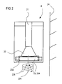
- FIG 2 and FIG 3 show a suction hood 2, 3 with a cylindric upper part 21, 31 as suction channel and a conical lower part 22, 32 as diffuser, on whose bottom a vortex generator 23, 33 is mounted.
- the diffuser adapts the diameter of the vortex channel to the diameter of the suction channel.
- the vortex generator 23, 33 sucks in air from the side and blows it with a tangential component into the interior 234, 334 of the vortex generator, so that a vortex is formed in the interior 234, 334 which continues downwards as a vortex air stream 236, 336 around an axis 231, 331.
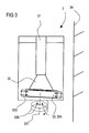
- FIG 3 shows a conical lower part 32 with an inclined bottom surface, on which the vortex generator 33 is mounted.
- the vortex generator 33 is tilted, which is shown in FIG 3 , and therefore, also the axis 331 of the vortex air stream 331 is tilted:
- the suction hood 3 is mounted next to a wall 34.
- the conical lower part 32 works, in this embodiment, as a stabilizing means for the vortex generator 33, as the vortex generator is or can be hold in an inclined position.
- the stabilizing means can be an intermediate part between the diffuser and the vortex generator, wherein the upper side of the intermediate part is inclined with respect to the bottom side, so that the vortex generator is hold in an inclined position.
- the stabilizing means is implemented by an inclined upper side of the vortex generator, so that the vortex generator is hold in an inclined position.
- a pivoting mechanism can be installed between the suction channel 31 and the vortex generator 33 so that the inclination of the vortex generator 33 can be adjusted as desired.
- FIG 4 and FIG 5 show a suction hood 4 with a vortex generator 43.
- the suction hood comprises a cylindric upper part 41 and a conical lower part 42, on whose bottom a vortex generator 43 is mounted.
- the vortex generator 43 sucks in air from the side and blows it with a tangential component into the interior 434 of the vortex generator, so that a vortex is formed in the interior 434 which continues downwards as a vortex air stream 436 around an axis 431.
- the stabilizing means is implemented as a skirt 433 which has a ring shaped form and which surrounds the inner surface of the vortex generator 43 and which surrounds the vortex air stream 436 in its upper portion.
- the skirt 433 can be shifted down from a first, upper position to a second, lower position.
- the skirt 433 is arranged substantially inside the vortex generator 43.
- the skirt 433 is arranged mostly below the vortex generator 43 so that the vortex generator 43 is extended downwards. This extension enlarges the cylindrical part of the suction area so that a vortex air stream 436 with higher stability can be formed.
- the vortex generation can be blocked in the first position, as the lateral openings towards the substantially cylindrical interior for guiding the air with a tangential component with respect to the cylindrical interior can be blocked by the skirt 433.
- a horizontal air stream can be generated inside the suction channel 41 which sucks the air directly into the suction channel.
- FIG 6 shows another embodiment wherein the stabilizing means 54 are suction means, by which a lateral suction 541 towards the suction hood 5 can be generated around the vortex air stream 536, so that the radial losses of the vortex generator 536 are reduced.
- the suction means 54 sucks with a low suction volume.
- the lateral suction 541 also improves the stability of the vortex.
- the suction hood in the shown embodiments is a vented hood, which is preferably connected to a duct system for extracting the sucked air out of a room, especially a kitchen.
- the suction hood can also be a recirculating hood, preferably with a filter, especially an activated charcoal filter, wherein the suction hood sucks the air in from the room air, especially in a kitchen, and blows the air back into the room again.
- a filter especially an activated charcoal filter
- the vortex generator comprises an at least substantially cylindrical interior and lateral openings towards the substantially cylindrical interior for guiding the air with a tangential component with respect to the cylindrical interior and fans or blowers for blowing air into the lateral openings.
- the vortex air stream is stable over time. This means that the vortex air stream does not dwindle to reappear again and that its position does not move over time. However, there is, dependent on the distance from the vortex generator, a point of rupture where the vortex air stream disappears or disperses. Improving the stability of the vortex air stream therefore means that the distance after which the vortex air stream disappears is made as long as possible.
- the suction hood can comprise, which is not shown in the figures, means which can generate an at least substantially horizontal air stream.
- the suction hood can be operated with the at least substantially horizontal air stream and/or with the vortex air stream.
Landscapes
- Engineering & Computer Science (AREA)
- Chemical & Material Sciences (AREA)
- Combustion & Propulsion (AREA)
- Mechanical Engineering (AREA)
- General Engineering & Computer Science (AREA)
- Ventilation (AREA)
- Cyclones (AREA)
- Air-Flow Control Members (AREA)
Abstract
a) comprising a vortex generator (33, 43, 53) for generating a vortex air stream (336, 436, 536),
b) wherein the vortex air stream comprises an at least substantially circular, cyclone, vortex and/or helix like air movement,
c) such that fumes or smoke can be pulled into the suction hood (3, 4, 5) by the vortex air stream,
d) comprising stabilizing means (32, 433, 54) for improving the stability of the vortex air stream.
Description
- The invention relates to a suction hood, preferably a vortex generator or tornado suction means.
- Known or traditional suction hoods, which also can be denominated as destructor hoods, range hoods, kitchen hoods, stove hoods, exhaust hoods, cooker hoods, extraction hoods, cooking canopy or ventilation hoods, are used to remove airborne grease, combustion products, smoke, odours and/or heat and steam, which is generated usually by a cooking process on a cooktop, normally by a combination of filtration and evacuation of the air. They usually comprise three main components: A skirt or capture panel to contain the rising gases (also known as the "effluent plume"), one or more grease filters, and a fan or tangential blower for forced ventilation.
- The fans or blowers create, when activated, an area of low pressure which takes effect spherically around the hood.
- The airborne grease, combustion products, smoke, odours, heat and steam generated by the cooking of food on the cooktop rise naturally in a vertical motion due to gravity effect, and enter the effective area of the hood to be captured by the low pressure area.
- The traditional hoods as described above present at least relatively low efficiency in treating the fumes from the cooktop as they suck-up equally air from the surrounding environment.
FIG 1a shows such a hood 1', where the gas is sucked in from all sides along paths shown by arrows 74'. - The pressure field 71' of a traditional hood 1' over a cooktop 7' is shown in
FIG 1b . The pressure field represents the effective suction volume of the hood. - In
WO 89/11926 A1 - In is an object of invention, to improve the characteristics of the suction means and the hood, especially the suction characteristics, preferably in a cost-effective way.
- This object is solved by a suction hood according to claim 1. Advantageous embodiments can be derived especially from the dependent claims.
- According to claim 1, the invention relates to a suction hood, preferably a vortex hood or tornado hood,
- a) comprising a vortex generator for generating a vortex air stream,
- b) wherein the vortex air stream comprises an at least substantially circular, cyclone, vortex and/or helix like air movement,
- c) such that fumes or smoke can be pulled into the suction hood by the vortex air stream,
characterized by - d) stabilizing means for improving the stability of the vortex air stream.
- An improved stability of the vortex air stream makes it possible to pull in the fumes in a more effective way. A vortex air stream with an improved stability is normally a vortex air stream which has a shape below the vortex generator which is extending as far as possible downwards and which is as close as possible to a cylindrical form.
- Preferably, the vortex air stream is stable over time, wherein the vortex air stream especially does not dwindle to reappear again and/or its position does not move over time. However, there is preferably , especially dependent on the distance from the vortex generator, a point of rupture where the vortex air stream disappears or disperses. Improving the stability of the vortex air stream therefore preferably means that the distance after which the vortex air stream disappears is made as long as possible.
- Preferably, the suction hood comprises a suction channel and/or a diffuser, wherein preferably the suction channel is arranged above the diffuser, wherein preferably the diffuser is arranged above the vortex generator and/or between the suction channel and the vortex generator, so that the diffuser adapts the cross section of the vortex generator to the cross section of the suction channel. In this case, it is possible that the suction channel has a smaller cross section than the vortex generator, so that the vortex generator can preferably be operated with a cross section which corresponds to at least part of the area to be sucked, especially the cooking area, whereas the suction channel can preferably be operated with an at least relatively small cross section so that the necessary space and costs are minimized or reduced.
- Preferably, the vortex air stream rotates around an axis and/or the vortex generator is arranged around an or the axis and/or the stabilizing means tilts the axis of the vortex generator and/or the vortex air stream with respect to a vertical direction, such that especially, in case the suction hood is mounted at a wall, the vortex air stream is or can be directed away from the wall. This embodiment can especially be used when the suction hood is mounted in front of a wall as it can reduce the effects of the wall and improve the vortex stability, as the vortex air stream can be deformed, in case it is arranged too close to a wall.
- Preferably, the stabilizing means is the or a diffuser, on which the vortex generator is or can be attached, wherein the diffuser comprises an inclined bottom side, so that the vortex generator is or can be hold in an inclined position and/or the stabilizing means is an intermediate part between the diffuser and the vortex generator, wherein the upper side of the intermediate part is inclined with respect to the bottom side, so that the vortex generator is hold in an inclined position and/or the stabilizing means is implemented by an inclined upper side of the vortex generator, so that the vortex generator is hold in an inclined position.
- Preferably, the stabilizing means is a, preferably ring shaped, skirt for at least partially surrounding the vortex air stream and/or for at least partially surrounding the inner surface of the vortex generator, wherein for improving the stability of the vortex air stream or for activating the vortex air stream, the skirt can be shifted down from a first position to a second position, wherein in the first position, the skirt is arranged at least substantially inside the vortex generator, wherein in the second position, the skirt is arranged at least substantially below the vortex generator so that the vortex generator is extended downwards, wherein preferably the skirt is slidably fixed along the inner surface of the vortex generator. This embodiment enlarges the area in which the vortex air stream is guided so that it can maintain its stability at least down to an area which is further downwards with respect to the suction hood.
- Preferably, the stabilizing means are suction means, by which laterally and/or vertically sucked air towards the suction hood can be generated at least partially around the vortex air stream,
so that the radial losses of the vortex generator are reduced, wherein the suction means preferably sucks with a low suction volume, wherein preferably the suction means is attached at the suction channel, so that the laterally sucked air is or can be mixed with the vortex air stream. Also this embodiment reduces the diffusion of the vortex air stream so that its stability is enhanced. - Preferably, the suction hood is designed as a vented hood, which is preferably connected to a duct system for extracting the sucked air out of a room, especially a kitchen, and/or the suction hood is designed as a recirculating hood, wherein it preferably comprises a filter, especially an activated charcoal filter, preferably to remove odour and smoke particles from the air, wherein the suction hood, after sucking in the air from a room, especially a kitchen, blows the preferably cleaned air back into the room again.
- Preferably, the vortex generator comprises an at least substantially cylindrical interior and/or lateral openings towards the substantially cylindrical interior for guiding the air with a tangential component with respect to the cylindrical interior and/or fans or blowers for blowing air into the lateral openings.
- Preferably, the suction hood comprises means which can generate an at least substantially horizontal air stream and/or the suction hood can be operated with the at least substantially horizontal air stream and/or with the vortex air stream.
- The invention will now be described in further details with references to the schematic figures, in which
- FIG 1a, 1b
- show conventional hoods, as described above,
- FIG 1c
- outlines the concept of a tornado suction hood,
- FIG 1d
- shows the pressure field of a hood system according to
FIG 1c , - FIG 2
- shows a suction hood according to the invention with a tiltable vortex generator in an untilted position,
- FIG 3
- shows a suction hood according to the invention with a tiltable vortex generator in a tilted position,
- FIG 4
- shows a suction hood with a movable skirt according to the invention in a first position,
- FIG 5
- shows the suction hood with a movable skirt according to the invention in a second position and in which
- FIG 6
- shows a suction hood with lateral suction means according to the invention.
-
FIG 1c outlines the concept of a tornado suction hood 1. Thearrows 75 represent the rotating column of air and thearrows 74 represent the suction draft. The combination of these two flows generates the tornado. The air is sucked in throughair inlets suction channel 13. - The
pressure field 71 of such a hood system 1 is shown inFIG 1d . The pressure field represents the effective suction volume of the hood. The generated vortex between thecooktop 7 and the hood 1 sucks in the fume from thecooktop 7 in a swirling motion. -
FIG 2 andFIG 3 show asuction hood upper part lower part - The vortex generator 23, 33 sucks in air from the side and blows it with a tangential component into the interior 234, 334 of the vortex generator, so that a vortex is formed in the interior 234, 334 which continues downwards as a
vortex air stream axis -
FIG 3 shows a conicallower part 32 with an inclined bottom surface, on which the vortex generator 33 is mounted. By mounting on the inclined bottom surface of the conicallower part 32, the vortex generator 33 is tilted, which is shown inFIG 3 , and therefore, also theaxis 331 of thevortex air stream 331 is tilted: Thesuction hood 3 is mounted next to awall 34. When the vortex generator 33 is tilted, the effect of thewall 34 is reduced and therefore the stability of vortex is improved. Therefore, the conicallower part 32 works, in this embodiment, as a stabilizing means for the vortex generator 33, as the vortex generator is or can be hold in an inclined position. - As an alternative, the stabilizing means can be an intermediate part between the diffuser and the vortex generator, wherein the upper side of the intermediate part is inclined with respect to the bottom side, so that the vortex generator is hold in an inclined position.
- As a further alternative, the stabilizing means is implemented by an inclined upper side of the vortex generator, so that the vortex generator is hold in an inclined position. Furthermore, a pivoting mechanism can be installed between the
suction channel 31 and the vortex generator 33 so that the inclination of the vortex generator 33 can be adjusted as desired. -
FIG 4 andFIG 5 show asuction hood 4 with a vortex generator 43. Again, the suction hood comprises a cylindricupper part 41 and a conicallower part 42, on whose bottom a vortex generator 43 is mounted. - The vortex generator 43 sucks in air from the side and blows it with a tangential component into the interior 434 of the vortex generator, so that a vortex is formed in the interior 434 which continues downwards as a
vortex air stream 436 around anaxis 431. - In this embodiment, the stabilizing means is implemented as a
skirt 433 which has a ring shaped form and which surrounds the inner surface of the vortex generator 43 and which surrounds thevortex air stream 436 in its upper portion. - For improving the stability of the vortex air stream, the
skirt 433 can be shifted down from a first, upper position to a second, lower position. - In the first position, which is shown in
FIG 4 , theskirt 433 is arranged substantially inside the vortex generator 43. - In the second position, which is shown in
FIG 5 , theskirt 433 is arranged mostly below the vortex generator 43 so that the vortex generator 43 is extended downwards. This extension enlarges the cylindrical part of the suction area so that avortex air stream 436 with higher stability can be formed. - As an alternative, the vortex generation can be blocked in the first position, as the lateral openings towards the substantially cylindrical interior for guiding the air with a tangential component with respect to the cylindrical interior can be blocked by the
skirt 433. In this case, a horizontal air stream can be generated inside thesuction channel 41 which sucks the air directly into the suction channel. -
FIG 6 shows another embodiment wherein the stabilizingmeans 54 are suction means, by which alateral suction 541 towards thesuction hood 5 can be generated around thevortex air stream 536, so that the radial losses of thevortex generator 536 are reduced. The suction means 54 sucks with a low suction volume. - By reducing the radial losses, the
lateral suction 541 also improves the stability of the vortex. - The suction hood in the shown embodiments is a vented hood, which is preferably connected to a duct system for extracting the sucked air out of a room, especially a kitchen.
- As an alternative or in addition, the suction hood can also be a recirculating hood, preferably with a filter, especially an activated charcoal filter, wherein the suction hood sucks the air in from the room air, especially in a kitchen, and blows the air back into the room again.
- The vortex generator comprises an at least substantially cylindrical interior and lateral openings towards the substantially cylindrical interior for guiding the air with a tangential component with respect to the cylindrical interior and fans or blowers for blowing air into the lateral openings.
- The vortex air stream is stable over time. This means that the vortex air stream does not dwindle to reappear again and that its position does not move over time. However, there is, dependent on the distance from the vortex generator, a point of rupture where the vortex air stream disappears or disperses. Improving the stability of the vortex air stream therefore means that the distance after which the vortex air stream disappears is made as long as possible.
- The suction hood can comprise, which is not shown in the figures, means which can generate an at least substantially horizontal air stream. In this case, the suction hood can be operated with the at least substantially horizontal air stream and/or with the vortex air stream.
Reference signs 1, 2, 4, 5 suction hoods 21, 41, 51 suction channels 22, 42, 52 diffusers 23, 43, 53 vortex generators 231, 431, 531 axis 541 lateral suction area 234, 434, 534 vortex interior area 236, 436, 536 vortex air stream 24, 34 wall 433 skirt 7, 7' cooktops 71, 71' pressure fields 74, 75, 74' air movement
Claims (9)
characterized by
Priority Applications (12)
| Application Number | Priority Date | Filing Date | Title |
|---|---|---|---|
| EP09007739.7A EP2196738B1 (en) | 2008-12-10 | 2009-06-12 | Suction hood |
| MX2011006053A MX2011006053A (en) | 2008-12-10 | 2009-12-10 | Suction hood. |
| US13/132,348 US9395090B2 (en) | 2008-12-10 | 2009-12-10 | Suction hood |
| CN200980149221.2A CN102348935B (en) | 2008-12-10 | 2009-12-10 | Suction hood |
| BRPI0922445A BRPI0922445B1 (en) | 2008-12-10 | 2009-12-10 | suction hood |
| JP2011539951A JP5615291B2 (en) | 2008-12-10 | 2009-12-10 | Inhalation hood |
| RU2011128323/03A RU2481529C2 (en) | 2008-12-10 | 2009-12-10 | Exhaust hood |
| CA2746390A CA2746390A1 (en) | 2008-12-10 | 2009-12-10 | Suction hood |
| KR1020117015361A KR20110094110A (en) | 2008-12-10 | 2009-12-10 | Suction hood |
| AU2009326529A AU2009326529B2 (en) | 2008-12-10 | 2009-12-10 | Suction hood |
| PCT/EP2009/008825 WO2010066423A2 (en) | 2008-12-10 | 2009-12-10 | Suction hood |
| EP09795698.1A EP2359069B1 (en) | 2008-12-10 | 2009-12-10 | suction hood |
Applications Claiming Priority (3)
| Application Number | Priority Date | Filing Date | Title |
|---|---|---|---|
| EP08021415.8A EP2196737B1 (en) | 2008-12-10 | 2008-12-10 | Suction Hood |
| EP08021414A EP2196736B1 (en) | 2008-12-10 | 2008-12-10 | Suction Hood |
| EP09007739.7A EP2196738B1 (en) | 2008-12-10 | 2009-06-12 | Suction hood |
Publications (3)
| Publication Number | Publication Date |
|---|---|
| EP2196738A2 true EP2196738A2 (en) | 2010-06-16 |
| EP2196738A3 EP2196738A3 (en) | 2011-07-06 |
| EP2196738B1 EP2196738B1 (en) | 2013-10-23 |
Family
ID=40972860
Family Applications (2)
| Application Number | Title | Priority Date | Filing Date |
|---|---|---|---|
| EP09007739.7A Active EP2196738B1 (en) | 2008-12-10 | 2009-06-12 | Suction hood |
| EP09795698.1A Active EP2359069B1 (en) | 2008-12-10 | 2009-12-10 | suction hood |
Family Applications After (1)
| Application Number | Title | Priority Date | Filing Date |
|---|---|---|---|
| EP09795698.1A Active EP2359069B1 (en) | 2008-12-10 | 2009-12-10 | suction hood |
Country Status (11)
| Country | Link |
|---|---|
| US (1) | US9395090B2 (en) |
| EP (2) | EP2196738B1 (en) |
| JP (1) | JP5615291B2 (en) |
| KR (1) | KR20110094110A (en) |
| CN (1) | CN102348935B (en) |
| AU (1) | AU2009326529B2 (en) |
| BR (1) | BRPI0922445B1 (en) |
| CA (1) | CA2746390A1 (en) |
| MX (1) | MX2011006053A (en) |
| RU (1) | RU2481529C2 (en) |
| WO (1) | WO2010066423A2 (en) |
Cited By (2)
| Publication number | Priority date | Publication date | Assignee | Title |
|---|---|---|---|---|
| EP2711096A3 (en) * | 2012-09-21 | 2014-04-23 | TRINC Corporation | Static eliminating and dust removing apparatus |
| CN111780178A (en) * | 2020-06-08 | 2020-10-16 | 华帝股份有限公司 | Range hood with vortex generating device |
Families Citing this family (9)
| Publication number | Priority date | Publication date | Assignee | Title |
|---|---|---|---|---|
| KR101934457B1 (en) * | 2011-11-17 | 2019-01-04 | 삼성전자주식회사 | Ventilation apparatus and ventilation system having the same |
| CN105879535A (en) * | 2014-09-06 | 2016-08-24 | 齐梓桢 | Atomization washing-type air purifier |
| KR101709278B1 (en) * | 2015-01-20 | 2017-02-23 | 김지하 | Local ventilator |
| KR102513469B1 (en) * | 2015-10-30 | 2023-03-24 | 삼성전자주식회사 | Air Conditioner |
| USD834047S1 (en) * | 2016-11-18 | 2018-11-20 | Samsung Electronics Co., Ltd. | Display screen or portion thereof with animated graphical user interface |
| KR102111328B1 (en) * | 2016-12-06 | 2020-05-15 | 엘지전자 주식회사 | Ventilating apparatus |
| CN116045323B (en) * | 2021-10-28 | 2025-11-21 | 佛山市顺德区美的洗涤电器制造有限公司 | Rectifying device for range hood and range hood |
| CN114453966A (en) * | 2022-02-28 | 2022-05-10 | 张传平 | Flow-adjustable intelligent cooling device for numerical control machine tool |
| CN116651885B (en) * | 2023-05-10 | 2025-10-31 | 珠海格力电器股份有限公司 | Air inlet pipeline with self-cleaning function and dust collecting device |
Citations (2)
| Publication number | Priority date | Publication date | Assignee | Title |
|---|---|---|---|---|
| WO1989011926A1 (en) | 1988-06-08 | 1989-12-14 | Hansen & Raagaard Aps | Ventilating system for mechanical local exhaustion |
| EP1887286A2 (en) | 2006-07-27 | 2008-02-13 | Electrolux Professional S.P.A. | Improvement in the ventilation arrangement of a fume extraction hood |
Family Cites Families (30)
| Publication number | Priority date | Publication date | Assignee | Title |
|---|---|---|---|---|
| US2783702A (en) * | 1950-09-30 | 1957-03-05 | Air Devices Inc | Adjustable vortex damper |
| US3205810A (en) * | 1962-09-04 | 1965-09-14 | Inland Steel Co | Adjustable hood construction for metallurgical furnace |
| FR1418065A (en) * | 1964-07-16 | 1965-11-19 | Loire Atel Forges | Method and device for regulating the capture of oxygen refining gases |
| US4062274A (en) * | 1976-06-07 | 1977-12-13 | Knab James V | Exhaust system for bone cement |
| MX161654A (en) * | 1984-05-05 | 1990-05-21 | Mexicano Investigacion | SEALING DEVICE BETWEEN CONVERTER AND FIREPLACE |
| JPS63297952A (en) * | 1987-05-29 | 1988-12-05 | Japan Steel Works Ltd:The | Method and device for discharging smoke in kitchen range |
| US4785722A (en) * | 1987-07-28 | 1988-11-22 | Hamilton Industries | Fume hood with step baffles |
| JPH02195139A (en) * | 1989-01-25 | 1990-08-01 | Seibu Electric Ind Co Ltd | Oven hood |
| JP2938256B2 (en) * | 1991-12-09 | 1999-08-23 | 高砂熱学工業株式会社 | Exhaust device |
| JP2596842Y2 (en) * | 1992-12-02 | 1999-06-21 | 富士工業株式会社 | Range food |
| JPH0875208A (en) * | 1994-09-02 | 1996-03-19 | Tsutomu Fukuba | Local exhaust device |
| JPH0942734A (en) * | 1995-07-24 | 1997-02-14 | Sun Wave Ind Co Ltd | Exhaust structure around heater |
| DE19758141C2 (en) * | 1997-12-19 | 1999-12-02 | Mannesmann Ag | Converter system |
| KR100423116B1 (en) * | 1998-03-30 | 2004-03-18 | 다이킨 고교 가부시키가이샤 | Air intake and blowing device |
| JP3327247B2 (en) * | 1999-01-14 | 2002-09-24 | ダイキン工業株式会社 | Ventilation equipment |
| JP2001174037A (en) * | 1999-07-01 | 2001-06-29 | Daikin Ind Ltd | Tornado-type intake / blower |
| JP2001027200A (en) * | 1999-07-13 | 2001-01-30 | Daikin Ind Ltd | Tornado-type intake / blower |
| JP3395736B2 (en) * | 1999-10-26 | 2003-04-14 | ダイキン工業株式会社 | Air supply and exhaust system |
| US20110005507A9 (en) * | 2001-01-23 | 2011-01-13 | Rick Bagwell | Real-time control of exhaust flow |
| JP3943358B2 (en) * | 2001-09-21 | 2007-07-11 | 富士工業株式会社 | Range hood fan |
| DE10208488A1 (en) * | 2002-02-27 | 2003-09-04 | Bsh Bosch Siemens Hausgeraete | Extractor hood and method for extracting and / or cleaning contaminated carriers |
| US6820609B2 (en) * | 2002-04-03 | 2004-11-23 | Vent-A-Hood Ltd. | Low-profile ventilation hood |
| FR2843054A1 (en) * | 2002-07-30 | 2004-02-06 | Claude Tagnon | Method for cleaning air by cyclone effect and filtration, comprises centrifugal fan which draws air through first filter and expels it through second complementary filter to form cyclonic air hood |
| US7147168B1 (en) * | 2003-08-11 | 2006-12-12 | Halton Company | Zone control of space conditioning system with varied uses |
| FR2851814B1 (en) * | 2003-02-27 | 2006-01-13 | Henry Abehssera | APPARATUS AND INSTALLATION FOR THE TREATMENT OF CULINARY GASEOUS EFFLUENTS |
| JP4526780B2 (en) * | 2003-04-30 | 2010-08-18 | 富士夫 堀 | Food equipment |
| JP4366236B2 (en) * | 2004-04-26 | 2009-11-18 | 邦昭 堀越 | Ventilation assist device in electromagnetic induction cookware |
| US8038515B2 (en) * | 2004-07-23 | 2011-10-18 | Oy Halton Group Ltd. | Control of exhaust systems |
| CN2804682Y (en) * | 2005-04-15 | 2006-08-09 | 大连明天实业有限公司 | Smoke purification and collection hood |
| US7699051B2 (en) * | 2005-06-08 | 2010-04-20 | Westen Industries, Inc. | Range hood |
-
2009
- 2009-06-12 EP EP09007739.7A patent/EP2196738B1/en active Active
- 2009-12-10 CN CN200980149221.2A patent/CN102348935B/en not_active Expired - Fee Related
- 2009-12-10 AU AU2009326529A patent/AU2009326529B2/en not_active Ceased
- 2009-12-10 US US13/132,348 patent/US9395090B2/en not_active Expired - Fee Related
- 2009-12-10 MX MX2011006053A patent/MX2011006053A/en active IP Right Grant
- 2009-12-10 BR BRPI0922445A patent/BRPI0922445B1/en not_active IP Right Cessation
- 2009-12-10 RU RU2011128323/03A patent/RU2481529C2/en not_active IP Right Cessation
- 2009-12-10 EP EP09795698.1A patent/EP2359069B1/en active Active
- 2009-12-10 CA CA2746390A patent/CA2746390A1/en not_active Abandoned
- 2009-12-10 KR KR1020117015361A patent/KR20110094110A/en not_active Ceased
- 2009-12-10 WO PCT/EP2009/008825 patent/WO2010066423A2/en not_active Ceased
- 2009-12-10 JP JP2011539951A patent/JP5615291B2/en not_active Expired - Fee Related
Patent Citations (2)
| Publication number | Priority date | Publication date | Assignee | Title |
|---|---|---|---|---|
| WO1989011926A1 (en) | 1988-06-08 | 1989-12-14 | Hansen & Raagaard Aps | Ventilating system for mechanical local exhaustion |
| EP1887286A2 (en) | 2006-07-27 | 2008-02-13 | Electrolux Professional S.P.A. | Improvement in the ventilation arrangement of a fume extraction hood |
Cited By (2)
| Publication number | Priority date | Publication date | Assignee | Title |
|---|---|---|---|---|
| EP2711096A3 (en) * | 2012-09-21 | 2014-04-23 | TRINC Corporation | Static eliminating and dust removing apparatus |
| CN111780178A (en) * | 2020-06-08 | 2020-10-16 | 华帝股份有限公司 | Range hood with vortex generating device |
Also Published As
| Publication number | Publication date |
|---|---|
| AU2009326529A1 (en) | 2011-06-23 |
| WO2010066423A3 (en) | 2011-11-10 |
| EP2196738A3 (en) | 2011-07-06 |
| CA2746390A1 (en) | 2010-06-17 |
| US9395090B2 (en) | 2016-07-19 |
| KR20110094110A (en) | 2011-08-19 |
| CN102348935B (en) | 2014-05-14 |
| JP2012511686A (en) | 2012-05-24 |
| BRPI0922445A2 (en) | 2019-05-28 |
| US20110240004A1 (en) | 2011-10-06 |
| BRPI0922445B1 (en) | 2020-01-14 |
| MX2011006053A (en) | 2011-06-24 |
| EP2196738B1 (en) | 2013-10-23 |
| RU2481529C2 (en) | 2013-05-10 |
| AU2009326529B2 (en) | 2015-04-09 |
| EP2359069A2 (en) | 2011-08-24 |
| RU2011128323A (en) | 2013-01-20 |
| EP2359069B1 (en) | 2013-11-20 |
| JP5615291B2 (en) | 2014-10-29 |
| CN102348935A (en) | 2012-02-08 |
| WO2010066423A2 (en) | 2010-06-17 |
Similar Documents
| Publication | Publication Date | Title |
|---|---|---|
| US9395090B2 (en) | Suction hood | |
| EP2359068B1 (en) | Suction hood | |
| EP2196736B1 (en) | Suction Hood | |
| EP2240726B1 (en) | Exhaust hood with an exhaust enhancement apparatus | |
| EP1887286B1 (en) | Improvement in the ventilation arrangement of a fume extraction hood | |
| JP2003207184A (en) | Supply and discharge structure of supply and exhaust type kitchen ventilation system | |
| HK1164424A (en) | Suction hood | |
| CN110274278A (en) | Fence type smoke exhaust ventilator | |
| HK1162067A (en) | Suction hood |
Legal Events
| Date | Code | Title | Description |
|---|---|---|---|
| PUAI | Public reference made under article 153(3) epc to a published international application that has entered the european phase |
Free format text: ORIGINAL CODE: 0009012 |
|
| AK | Designated contracting states |
Kind code of ref document: A2 Designated state(s): AT BE BG CH CY CZ DE DK EE ES FI FR GB GR HR HU IE IS IT LI LT LU LV MC MK MT NL NO PL PT RO SE SI SK TR |
|
| AX | Request for extension of the european patent |
Extension state: AL BA RS |
|
| RAP1 | Party data changed (applicant data changed or rights of an application transferred) |
Owner name: ELECTROLUX HOME PRODUCTS CORPORATION N.V. |
|
| PUAL | Search report despatched |
Free format text: ORIGINAL CODE: 0009013 |
|
| AK | Designated contracting states |
Kind code of ref document: A3 Designated state(s): AT BE BG CH CY CZ DE DK EE ES FI FR GB GR HR HU IE IS IT LI LT LU LV MC MK MT NL NO PL PT RO SE SI SK TR |
|
| AX | Request for extension of the european patent |
Extension state: AL BA RS |
|
| RAP1 | Party data changed (applicant data changed or rights of an application transferred) |
Owner name: ELECTROLUX HOME PRODUCTS CORPORATION N.V. |
|
| 17P | Request for examination filed |
Effective date: 20111201 |
|
| GRAP | Despatch of communication of intention to grant a patent |
Free format text: ORIGINAL CODE: EPIDOSNIGR1 |
|
| INTG | Intention to grant announced |
Effective date: 20130628 |
|
| GRAS | Grant fee paid |
Free format text: ORIGINAL CODE: EPIDOSNIGR3 |
|
| GRAA | (expected) grant |
Free format text: ORIGINAL CODE: 0009210 |
|
| AK | Designated contracting states |
Kind code of ref document: B1 Designated state(s): AT BE BG CH CY CZ DE DK EE ES FI FR GB GR HR HU IE IS IT LI LT LU LV MC MK MT NL NO PL PT RO SE SI SK TR |
|
| REG | Reference to a national code |
Ref country code: GB Ref legal event code: FG4D |
|
| REG | Reference to a national code |
Ref country code: CH Ref legal event code: EP |
|
| REG | Reference to a national code |
Ref country code: AT Ref legal event code: REF Ref document number: 637817 Country of ref document: AT Kind code of ref document: T Effective date: 20131115 |
|
| REG | Reference to a national code |
Ref country code: IE Ref legal event code: FG4D |
|
| REG | Reference to a national code |
Ref country code: DE Ref legal event code: R096 Ref document number: 602009019564 Country of ref document: DE Effective date: 20131219 |
|
| REG | Reference to a national code |
Ref country code: NL Ref legal event code: VDEP Effective date: 20131023 |
|
| REG | Reference to a national code |
Ref country code: AT Ref legal event code: MK05 Ref document number: 637817 Country of ref document: AT Kind code of ref document: T Effective date: 20131023 |
|
| REG | Reference to a national code |
Ref country code: LT Ref legal event code: MG4D |
|
| PG25 | Lapsed in a contracting state [announced via postgrant information from national office to epo] |
Ref country code: IS Free format text: LAPSE BECAUSE OF FAILURE TO SUBMIT A TRANSLATION OF THE DESCRIPTION OR TO PAY THE FEE WITHIN THE PRESCRIBED TIME-LIMIT Effective date: 20140223 Ref country code: NL Free format text: LAPSE BECAUSE OF FAILURE TO SUBMIT A TRANSLATION OF THE DESCRIPTION OR TO PAY THE FEE WITHIN THE PRESCRIBED TIME-LIMIT Effective date: 20131023 Ref country code: NO Free format text: LAPSE BECAUSE OF FAILURE TO SUBMIT A TRANSLATION OF THE DESCRIPTION OR TO PAY THE FEE WITHIN THE PRESCRIBED TIME-LIMIT Effective date: 20140123 Ref country code: SE Free format text: LAPSE BECAUSE OF FAILURE TO SUBMIT A TRANSLATION OF THE DESCRIPTION OR TO PAY THE FEE WITHIN THE PRESCRIBED TIME-LIMIT Effective date: 20131023 Ref country code: FI Free format text: LAPSE BECAUSE OF FAILURE TO SUBMIT A TRANSLATION OF THE DESCRIPTION OR TO PAY THE FEE WITHIN THE PRESCRIBED TIME-LIMIT Effective date: 20131023 Ref country code: LT Free format text: LAPSE BECAUSE OF FAILURE TO SUBMIT A TRANSLATION OF THE DESCRIPTION OR TO PAY THE FEE WITHIN THE PRESCRIBED TIME-LIMIT Effective date: 20131023 Ref country code: HR Free format text: LAPSE BECAUSE OF FAILURE TO SUBMIT A TRANSLATION OF THE DESCRIPTION OR TO PAY THE FEE WITHIN THE PRESCRIBED TIME-LIMIT Effective date: 20131023 Ref country code: BE Free format text: LAPSE BECAUSE OF FAILURE TO SUBMIT A TRANSLATION OF THE DESCRIPTION OR TO PAY THE FEE WITHIN THE PRESCRIBED TIME-LIMIT Effective date: 20131023 |
|
| PG25 | Lapsed in a contracting state [announced via postgrant information from national office to epo] |
Ref country code: ES Free format text: LAPSE BECAUSE OF FAILURE TO SUBMIT A TRANSLATION OF THE DESCRIPTION OR TO PAY THE FEE WITHIN THE PRESCRIBED TIME-LIMIT Effective date: 20131023 Ref country code: LV Free format text: LAPSE BECAUSE OF FAILURE TO SUBMIT A TRANSLATION OF THE DESCRIPTION OR TO PAY THE FEE WITHIN THE PRESCRIBED TIME-LIMIT Effective date: 20131023 Ref country code: AT Free format text: LAPSE BECAUSE OF FAILURE TO SUBMIT A TRANSLATION OF THE DESCRIPTION OR TO PAY THE FEE WITHIN THE PRESCRIBED TIME-LIMIT Effective date: 20131023 Ref country code: CY Free format text: LAPSE BECAUSE OF FAILURE TO SUBMIT A TRANSLATION OF THE DESCRIPTION OR TO PAY THE FEE WITHIN THE PRESCRIBED TIME-LIMIT Effective date: 20131023 |
|
| PG25 | Lapsed in a contracting state [announced via postgrant information from national office to epo] |
Ref country code: PT Free format text: LAPSE BECAUSE OF FAILURE TO SUBMIT A TRANSLATION OF THE DESCRIPTION OR TO PAY THE FEE WITHIN THE PRESCRIBED TIME-LIMIT Effective date: 20140224 |
|
| REG | Reference to a national code |
Ref country code: DE Ref legal event code: R097 Ref document number: 602009019564 Country of ref document: DE |
|
| PG25 | Lapsed in a contracting state [announced via postgrant information from national office to epo] |
Ref country code: EE Free format text: LAPSE BECAUSE OF FAILURE TO SUBMIT A TRANSLATION OF THE DESCRIPTION OR TO PAY THE FEE WITHIN THE PRESCRIBED TIME-LIMIT Effective date: 20131023 |
|
| PG25 | Lapsed in a contracting state [announced via postgrant information from national office to epo] |
Ref country code: CZ Free format text: LAPSE BECAUSE OF FAILURE TO SUBMIT A TRANSLATION OF THE DESCRIPTION OR TO PAY THE FEE WITHIN THE PRESCRIBED TIME-LIMIT Effective date: 20131023 Ref country code: RO Free format text: LAPSE BECAUSE OF FAILURE TO SUBMIT A TRANSLATION OF THE DESCRIPTION OR TO PAY THE FEE WITHIN THE PRESCRIBED TIME-LIMIT Effective date: 20131023 Ref country code: SK Free format text: LAPSE BECAUSE OF FAILURE TO SUBMIT A TRANSLATION OF THE DESCRIPTION OR TO PAY THE FEE WITHIN THE PRESCRIBED TIME-LIMIT Effective date: 20131023 Ref country code: PL Free format text: LAPSE BECAUSE OF FAILURE TO SUBMIT A TRANSLATION OF THE DESCRIPTION OR TO PAY THE FEE WITHIN THE PRESCRIBED TIME-LIMIT Effective date: 20131023 |
|
| PLBE | No opposition filed within time limit |
Free format text: ORIGINAL CODE: 0009261 |
|
| STAA | Information on the status of an ep patent application or granted ep patent |
Free format text: STATUS: NO OPPOSITION FILED WITHIN TIME LIMIT |
|
| PG25 | Lapsed in a contracting state [announced via postgrant information from national office to epo] |
Ref country code: DK Free format text: LAPSE BECAUSE OF FAILURE TO SUBMIT A TRANSLATION OF THE DESCRIPTION OR TO PAY THE FEE WITHIN THE PRESCRIBED TIME-LIMIT Effective date: 20131023 |
|
| 26N | No opposition filed |
Effective date: 20140724 |
|
| REG | Reference to a national code |
Ref country code: DE Ref legal event code: R097 Ref document number: 602009019564 Country of ref document: DE Effective date: 20140724 |
|
| PG25 | Lapsed in a contracting state [announced via postgrant information from national office to epo] |
Ref country code: LU Free format text: LAPSE BECAUSE OF FAILURE TO SUBMIT A TRANSLATION OF THE DESCRIPTION OR TO PAY THE FEE WITHIN THE PRESCRIBED TIME-LIMIT Effective date: 20140612 Ref country code: MC Free format text: LAPSE BECAUSE OF FAILURE TO SUBMIT A TRANSLATION OF THE DESCRIPTION OR TO PAY THE FEE WITHIN THE PRESCRIBED TIME-LIMIT Effective date: 20131023 |
|
| REG | Reference to a national code |
Ref country code: CH Ref legal event code: PL |
|
| PG25 | Lapsed in a contracting state [announced via postgrant information from national office to epo] |
Ref country code: SI Free format text: LAPSE BECAUSE OF FAILURE TO SUBMIT A TRANSLATION OF THE DESCRIPTION OR TO PAY THE FEE WITHIN THE PRESCRIBED TIME-LIMIT Effective date: 20131023 |
|
| REG | Reference to a national code |
Ref country code: IE Ref legal event code: MM4A |
|
| PG25 | Lapsed in a contracting state [announced via postgrant information from national office to epo] |
Ref country code: CH Free format text: LAPSE BECAUSE OF NON-PAYMENT OF DUE FEES Effective date: 20140630 Ref country code: LI Free format text: LAPSE BECAUSE OF NON-PAYMENT OF DUE FEES Effective date: 20140630 Ref country code: IE Free format text: LAPSE BECAUSE OF NON-PAYMENT OF DUE FEES Effective date: 20140612 |
|
| PG25 | Lapsed in a contracting state [announced via postgrant information from national office to epo] |
Ref country code: MT Free format text: LAPSE BECAUSE OF FAILURE TO SUBMIT A TRANSLATION OF THE DESCRIPTION OR TO PAY THE FEE WITHIN THE PRESCRIBED TIME-LIMIT Effective date: 20131023 |
|
| REG | Reference to a national code |
Ref country code: FR Ref legal event code: PLFP Year of fee payment: 8 |
|
| PG25 | Lapsed in a contracting state [announced via postgrant information from national office to epo] |
Ref country code: GR Free format text: LAPSE BECAUSE OF FAILURE TO SUBMIT A TRANSLATION OF THE DESCRIPTION OR TO PAY THE FEE WITHIN THE PRESCRIBED TIME-LIMIT Effective date: 20140124 Ref country code: BG Free format text: LAPSE BECAUSE OF FAILURE TO SUBMIT A TRANSLATION OF THE DESCRIPTION OR TO PAY THE FEE WITHIN THE PRESCRIBED TIME-LIMIT Effective date: 20131023 |
|
| PG25 | Lapsed in a contracting state [announced via postgrant information from national office to epo] |
Ref country code: TR Free format text: LAPSE BECAUSE OF FAILURE TO SUBMIT A TRANSLATION OF THE DESCRIPTION OR TO PAY THE FEE WITHIN THE PRESCRIBED TIME-LIMIT Effective date: 20131023 Ref country code: HU Free format text: LAPSE BECAUSE OF FAILURE TO SUBMIT A TRANSLATION OF THE DESCRIPTION OR TO PAY THE FEE WITHIN THE PRESCRIBED TIME-LIMIT; INVALID AB INITIO Effective date: 20090612 |
|
| REG | Reference to a national code |
Ref country code: FR Ref legal event code: PLFP Year of fee payment: 9 |
|
| REG | Reference to a national code |
Ref country code: FR Ref legal event code: PLFP Year of fee payment: 10 |
|
| PG25 | Lapsed in a contracting state [announced via postgrant information from national office to epo] |
Ref country code: MK Free format text: LAPSE BECAUSE OF FAILURE TO SUBMIT A TRANSLATION OF THE DESCRIPTION OR TO PAY THE FEE WITHIN THE PRESCRIBED TIME-LIMIT Effective date: 20131023 |
|
| P01 | Opt-out of the competence of the unified patent court (upc) registered |
Effective date: 20230625 |
|
| PGFP | Annual fee paid to national office [announced via postgrant information from national office to epo] |
Ref country code: DE Payment date: 20250626 Year of fee payment: 17 |
|
| PGFP | Annual fee paid to national office [announced via postgrant information from national office to epo] |
Ref country code: GB Payment date: 20250617 Year of fee payment: 17 |
|
| PGFP | Annual fee paid to national office [announced via postgrant information from national office to epo] |
Ref country code: FR Payment date: 20250624 Year of fee payment: 17 |
|
| PGFP | Annual fee paid to national office [announced via postgrant information from national office to epo] |
Ref country code: IT Payment date: 20250623 Year of fee payment: 17 |