EP2196594B1 - Element for cladding buildings - Google Patents
Element for cladding buildings Download PDFInfo
- Publication number
- EP2196594B1 EP2196594B1 EP09178519.6A EP09178519A EP2196594B1 EP 2196594 B1 EP2196594 B1 EP 2196594B1 EP 09178519 A EP09178519 A EP 09178519A EP 2196594 B1 EP2196594 B1 EP 2196594B1
- Authority
- EP
- European Patent Office
- Prior art keywords
- structural element
- frame
- panel
- profile
- structural
- Prior art date
- Legal status (The legal status is an assumption and is not a legal conclusion. Google has not performed a legal analysis and makes no representation as to the accuracy of the status listed.)
- Active
Links
- 238000005253 cladding Methods 0.000 title claims description 8
- 238000007789 sealing Methods 0.000 claims description 32
- 125000006850 spacer group Chemical group 0.000 claims description 14
- 238000009434 installation Methods 0.000 claims description 5
- 238000004519 manufacturing process Methods 0.000 claims description 4
- 230000015572 biosynthetic process Effects 0.000 claims 1
- XLYOFNOQVPJJNP-UHFFFAOYSA-N water Substances O XLYOFNOQVPJJNP-UHFFFAOYSA-N 0.000 description 17
- 239000002184 metal Substances 0.000 description 7
- 229920003023 plastic Polymers 0.000 description 6
- 239000011449 brick Substances 0.000 description 5
- 238000000034 method Methods 0.000 description 5
- 239000004033 plastic Substances 0.000 description 5
- 238000004026 adhesive bonding Methods 0.000 description 4
- 238000010276 construction Methods 0.000 description 4
- 230000000694 effects Effects 0.000 description 4
- 230000005494 condensation Effects 0.000 description 3
- 238000009833 condensation Methods 0.000 description 3
- 239000007921 spray Substances 0.000 description 3
- 230000005484 gravity Effects 0.000 description 2
- 230000002093 peripheral effect Effects 0.000 description 2
- 239000000565 sealant Substances 0.000 description 2
- 101100498160 Mus musculus Dach1 gene Proteins 0.000 description 1
- 238000009749 continuous casting Methods 0.000 description 1
- 238000005520 cutting process Methods 0.000 description 1
- 230000001419 dependent effect Effects 0.000 description 1
- 229920001971 elastomer Polymers 0.000 description 1
- 239000000806 elastomer Substances 0.000 description 1
- 239000012530 fluid Substances 0.000 description 1
- 239000011521 glass Substances 0.000 description 1
- 229920001903 high density polyethylene Polymers 0.000 description 1
- 239000004700 high-density polyethylene Substances 0.000 description 1
- 239000007788 liquid Substances 0.000 description 1
- 238000012423 maintenance Methods 0.000 description 1
- 239000000463 material Substances 0.000 description 1
- 239000012528 membrane Substances 0.000 description 1
- 239000003595 mist Substances 0.000 description 1
- 230000003287 optical effect Effects 0.000 description 1
- 230000035515 penetration Effects 0.000 description 1
- 229920001296 polysiloxane Polymers 0.000 description 1
- 229920001343 polytetrafluoroethylene Polymers 0.000 description 1
- 238000010248 power generation Methods 0.000 description 1
- 238000009418 renovation Methods 0.000 description 1
- 230000000717 retained effect Effects 0.000 description 1
- 229920002379 silicone rubber Polymers 0.000 description 1
- 239000004945 silicone rubber Substances 0.000 description 1
- 239000004590 silicone sealant Substances 0.000 description 1
- 238000005476 soldering Methods 0.000 description 1
- 238000011144 upstream manufacturing Methods 0.000 description 1
- 238000003466 welding Methods 0.000 description 1
Images


Classifications
-
- E—FIXED CONSTRUCTIONS
- E04—BUILDING
- E04D—ROOF COVERINGS; SKY-LIGHTS; GUTTERS; ROOF-WORKING TOOLS
- E04D3/00—Roof covering by making use of flat or curved slabs or stiff sheets
- E04D3/02—Roof covering by making use of flat or curved slabs or stiff sheets of plane slabs, slates, or sheets, or in which the cross-section is unimportant
-
- F—MECHANICAL ENGINEERING; LIGHTING; HEATING; WEAPONS; BLASTING
- F24—HEATING; RANGES; VENTILATING
- F24S—SOLAR HEAT COLLECTORS; SOLAR HEAT SYSTEMS
- F24S20/00—Solar heat collectors specially adapted for particular uses or environments
- F24S20/60—Solar heat collectors integrated in fixed constructions, e.g. in buildings
- F24S20/67—Solar heat collectors integrated in fixed constructions, e.g. in buildings in the form of roof constructions
-
- F—MECHANICAL ENGINEERING; LIGHTING; HEATING; WEAPONS; BLASTING
- F24—HEATING; RANGES; VENTILATING
- F24S—SOLAR HEAT COLLECTORS; SOLAR HEAT SYSTEMS
- F24S25/00—Arrangement of stationary mountings or supports for solar heat collector modules
- F24S25/20—Peripheral frames for modules
-
- F—MECHANICAL ENGINEERING; LIGHTING; HEATING; WEAPONS; BLASTING
- F24—HEATING; RANGES; VENTILATING
- F24S—SOLAR HEAT COLLECTORS; SOLAR HEAT SYSTEMS
- F24S40/00—Safety or protection arrangements of solar heat collectors; Preventing malfunction of solar heat collectors
- F24S40/40—Preventing corrosion; Protecting against dirt or contamination
- F24S40/44—Draining rainwater or condensation
-
- H—ELECTRICITY
- H02—GENERATION; CONVERSION OR DISTRIBUTION OF ELECTRIC POWER
- H02S—GENERATION OF ELECTRIC POWER BY CONVERSION OF INFRARED RADIATION, VISIBLE LIGHT OR ULTRAVIOLET LIGHT, e.g. USING PHOTOVOLTAIC [PV] MODULES
- H02S20/00—Supporting structures for PV modules
- H02S20/20—Supporting structures directly fixed to an immovable object
- H02S20/22—Supporting structures directly fixed to an immovable object specially adapted for buildings
- H02S20/23—Supporting structures directly fixed to an immovable object specially adapted for buildings specially adapted for roof structures
-
- F—MECHANICAL ENGINEERING; LIGHTING; HEATING; WEAPONS; BLASTING
- F24—HEATING; RANGES; VENTILATING
- F24S—SOLAR HEAT COLLECTORS; SOLAR HEAT SYSTEMS
- F24S20/00—Solar heat collectors specially adapted for particular uses or environments
- F24S2020/10—Solar modules layout; Modular arrangements
- F24S2020/13—Overlaying arrangements similar to roof tiles
-
- F—MECHANICAL ENGINEERING; LIGHTING; HEATING; WEAPONS; BLASTING
- F24—HEATING; RANGES; VENTILATING
- F24S—SOLAR HEAT COLLECTORS; SOLAR HEAT SYSTEMS
- F24S25/00—Arrangement of stationary mountings or supports for solar heat collector modules
- F24S2025/01—Special support components; Methods of use
- F24S2025/014—Methods for installing support elements
-
- F—MECHANICAL ENGINEERING; LIGHTING; HEATING; WEAPONS; BLASTING
- F24—HEATING; RANGES; VENTILATING
- F24S—SOLAR HEAT COLLECTORS; SOLAR HEAT SYSTEMS
- F24S25/00—Arrangement of stationary mountings or supports for solar heat collector modules
- F24S2025/01—Special support components; Methods of use
- F24S2025/015—Supports with play between elements
-
- Y—GENERAL TAGGING OF NEW TECHNOLOGICAL DEVELOPMENTS; GENERAL TAGGING OF CROSS-SECTIONAL TECHNOLOGIES SPANNING OVER SEVERAL SECTIONS OF THE IPC; TECHNICAL SUBJECTS COVERED BY FORMER USPC CROSS-REFERENCE ART COLLECTIONS [XRACs] AND DIGESTS
- Y02—TECHNOLOGIES OR APPLICATIONS FOR MITIGATION OR ADAPTATION AGAINST CLIMATE CHANGE
- Y02B—CLIMATE CHANGE MITIGATION TECHNOLOGIES RELATED TO BUILDINGS, e.g. HOUSING, HOUSE APPLIANCES OR RELATED END-USER APPLICATIONS
- Y02B10/00—Integration of renewable energy sources in buildings
- Y02B10/10—Photovoltaic [PV]
-
- Y—GENERAL TAGGING OF NEW TECHNOLOGICAL DEVELOPMENTS; GENERAL TAGGING OF CROSS-SECTIONAL TECHNOLOGIES SPANNING OVER SEVERAL SECTIONS OF THE IPC; TECHNICAL SUBJECTS COVERED BY FORMER USPC CROSS-REFERENCE ART COLLECTIONS [XRACs] AND DIGESTS
- Y02—TECHNOLOGIES OR APPLICATIONS FOR MITIGATION OR ADAPTATION AGAINST CLIMATE CHANGE
- Y02B—CLIMATE CHANGE MITIGATION TECHNOLOGIES RELATED TO BUILDINGS, e.g. HOUSING, HOUSE APPLIANCES OR RELATED END-USER APPLICATIONS
- Y02B10/00—Integration of renewable energy sources in buildings
- Y02B10/20—Solar thermal
-
- Y—GENERAL TAGGING OF NEW TECHNOLOGICAL DEVELOPMENTS; GENERAL TAGGING OF CROSS-SECTIONAL TECHNOLOGIES SPANNING OVER SEVERAL SECTIONS OF THE IPC; TECHNICAL SUBJECTS COVERED BY FORMER USPC CROSS-REFERENCE ART COLLECTIONS [XRACs] AND DIGESTS
- Y02—TECHNOLOGIES OR APPLICATIONS FOR MITIGATION OR ADAPTATION AGAINST CLIMATE CHANGE
- Y02E—REDUCTION OF GREENHOUSE GAS [GHG] EMISSIONS, RELATED TO ENERGY GENERATION, TRANSMISSION OR DISTRIBUTION
- Y02E10/00—Energy generation through renewable energy sources
- Y02E10/40—Solar thermal energy, e.g. solar towers
- Y02E10/47—Mountings or tracking
-
- Y—GENERAL TAGGING OF NEW TECHNOLOGICAL DEVELOPMENTS; GENERAL TAGGING OF CROSS-SECTIONAL TECHNOLOGIES SPANNING OVER SEVERAL SECTIONS OF THE IPC; TECHNICAL SUBJECTS COVERED BY FORMER USPC CROSS-REFERENCE ART COLLECTIONS [XRACs] AND DIGESTS
- Y02—TECHNOLOGIES OR APPLICATIONS FOR MITIGATION OR ADAPTATION AGAINST CLIMATE CHANGE
- Y02E—REDUCTION OF GREENHOUSE GAS [GHG] EMISSIONS, RELATED TO ENERGY GENERATION, TRANSMISSION OR DISTRIBUTION
- Y02E10/00—Energy generation through renewable energy sources
- Y02E10/50—Photovoltaic [PV] energy
Definitions
- the invention relates to a component for covering buildings, in particular pitched roofs or facades, according to the preamble of the independent claim.
- roofs or facades of buildings are to be equipped with photovoltaic modules, they can be mounted on an existing façade or an existing roof, i. they are mounted on the façade or the roof with a suitable, usually complicated assembly construction.
- the existing roof skin such as a tile roof, can continue to be used and the photovoltaic modules do not have to perform a sealing function.
- the assembly structure must be individually adapted to a particular roof. In terms of cost, this method is particularly advantageous for existing roofs and facades.
- appropriately designed photovoltaic modules themselves form the dense lining of the roof or the facade. This option is particularly advantageous for new buildings or larger renovations, since the cost of covering the roof can be partially saved and thus the total construction costs can be reduced. Another advantage of such a solution is a more uniform optical appearance, and thus an aesthetically pleasing effect.
- FR 2465315 discloses a device according to the preamble of claim 1 and shows a photovoltaic module, which is fitted in a metal profile frame, so that there is a plate-shaped photovoltaic device.
- the photovoltaic module is sealed in a circumferential profile of the frame.
- the profile frame is designed such that the components such as brick can be installed in a scaly overlapping manner.
- the profile frame adjacent components interlock, so that there is a rainproof roof skin.
- the photovoltaic devices are fixed like conventional bricks with brackets on the roof battens. The construction as a small brick is disadvantageous for use as a photovoltaic module for electrical reasons.
- EP 1060520 shows a photovoltaic device, which corresponds in size to conventional photovoltaic modules, and therefore much larger than conventional bricks.
- the illustrated photovoltaic device has laterally a profile frame, which engages in the profile frame of the adjacent component, and thus creates a rain-tight connection.
- the overhead profile has a horizontal drainage channel, and means for attaching the device to the roof structure. On the bottom side, the profile is designed to only support the photovoltaic module but not cover it on top of the light receiving top.
- EP 1703037 shows a photovoltaic device, in which on the building side facing the component supporting devices are arranged, which cooperate with support elements which are mounted on a substructure, such as the roof battens.
- a construction with side frame profiles that interlock has the advantage that in the fall direction the profile below forms a drainage channel through which the rainwater can flow.
- this design has the disadvantage that the laying of the individual components must necessarily be made in a certain horizontal and vertical order. In the maintenance or repair of individual components, this can lead to problems.
- EP 1362967 shows a system in which each between two rows of adjacent components in the direction of fall a continuous, upwardly open rail is arranged.
- the side frame profiles engage in this rail, so that forms a continuous drainage channel and at the same time a rain-tight lateral connection between the components in the direction of fall. Individual components are so accessible, without the laterally adjacent components are affected.
- An object of the invention is to provide a device of the type mentioned, in particular a photovoltaic device, which does not have the above-mentioned and other disadvantages.
- Another object of the invention is to provide a component which makes it possible to cover a pitched roof or a facade from top to bottom.
- Another object of the invention is to provide a component which makes it possible to replace individual components in a finished building cladding without having to remove other components.
- Yet another object of the invention is to provide a component which is dispensed without additional, separate plastic sealing elements.
- Another object of the invention is to provide components with which roofs and facades can be covered rainproof, with the least possible material consumption.
- a device according to the invention should also be inexpensive to produce in smaller series.
- An inventive component according to claim 1 is provided for rain-tight covering a building exterior, in particular a pitched roof or a facade, with a plurality of overlapping components.
- the component comprises a frame and a panel fixed in or on this frame.
- the frame has an upper profile with two or more sealing lips projecting towards the outer weather side and a lower profile with two or more sealing lips projecting inwards away from the weather side.
- the upper or lower profiles are designed such that they can be brought into engagement with a lower or upper profile of an adjacent structurally identical component, resulting in a labyrinth seal.
- Rainproof means in this context of the invention described not absolutely waterproof, but tight against the ingress of water due to external weather conditions, especially rain.
- the lower and upper profiles of directly adjacent components do not come into contact with each other. Instead, they have a certain amount of play, so that, given a thermal expansion of the components, no mechanical stresses can build up due to a temperature change. This is particularly important for components with photovoltaic panels, as they heat and cool very quickly due to the dark color, so that over the course of a day can result in a significant change in length.
- the panel is preferably kept sealed in the frame.
- Said panel may be a photovoltaic module, or a solar collector module for the production of hot water, or even a simple cover without additional function, such as sheet metal, glass, or transparent plastic.
- the labyrinth seal in which the sealing lips of the interlocking profiles are arranged alternately, prevents flowing in the direction of fall on the roof running water under the components. It also effectively prevents the ingress of mist or water spray, and captures condensation.
- the upper and lower profile of the frame is designed such that the upper profile by a Pivoting movement along a pivot axis parallel to an upper edge of the component with a lower profile of an above the component mounted on a substructure identical component can be brought into engagement.
- components can be mounted in this way from above, from the ridge, down towards the eaves, with already assembled components must not be solved, moved or raised.
- An assembler can work from below the covered roof during installation, taking a comparatively comfortable posture and a secure footing. There is also a reduced risk of accidentally damaging already installed components.
- the frame of a component according to the invention has two lateral profiles, with two or more inwardly projecting sealing lips.
- the panel may be disposed in a U-shaped groove of the frame and / or on a mounting surface of the frame.
- the panel and the frame of the device form a substantially watertight surface.
- the upper profile has at least one horizontal gutter.
- the panel of a device according to the invention may be, for example, a photovoltaic module or a solar collector module.
- this component is constructed modularly from individual parts which can be combined as required.
- An inventive building cladding in particular for a pitched roof, has a plurality of such novel components.
- a slanted roof according to the invention and a building facade according to the invention have as or more components according to the invention.
- a power generation plant according to the invention in particular a photovoltaic plant or a solar collector plant, have one or more components according to the invention.
- a frame with a peripheral mounting surface is provided. Subsequently, a panel is placed on the mounting surface of the frame, and a seal is applied between an outer edge and the edge of the panel. The seal forms a watertight surface of the device with the frame and the panel.
- FIG. 1 An exemplary embodiment of a device 1 according to the invention is shown in FIG FIG. 1 shown (the support member is not shown).
- FIG. 3 shows the same component in an exploded view, with the panel omitted.
- a rectangular panel 12 is held on all four sides by a peripheral frame 11.
- the seal between frame and panel may be a silicone rubber seal or a circumferential sealing lip made of a suitable elastomer.
- the frame 11 consists essentially of four frame profiles 2, 2 ', 3, 4, which have a directed against the center U-shaped groove in which the panel is sealingly mounted.
- the frame profiles are preferably made Light metal manufactured by continuous casting. In order to form the frame, the profiles are preferably screwed together, being provided for this purpose in the illustrated embodiment access openings 24 for a tool. Alternatively, other fastening techniques are conceivable, for example soldering, gluing, welding or riveting.
- the structure of the frame of simple frame profiles in addition to reduced costs and the advantage that can be made by simply cutting the profiles very quickly the frame for a panel of any size.
- special dimensioning requirements can be taken into account without additional costs, and on the other hand purchased photovoltaic modules can be very easily installed in a component according to the invention.
- the corners of the device in the installed state are not visible, can be dispensed with complex corner finishes. Should the replacement of a component become necessary at a later date, but the corresponding frame profiles are no longer available, the component to be replaced can also be disassembled, the panel replaced, and the old frame profiles reassembled to form a new component.
- the dimensions of the comparatively small dimensioned component in FIG. 1 is to be understood only as an example. Modern photovoltaic panels have much larger dimensions, for example 80 cm X 160 cm.
- the two lateral profiles 2, 2 ' have a U-shaped groove for receiving the panel 12 and an inner 22 and an outer 21 sealing lip.
- the two profiles 2, 2 ' are identical, and differ only in their orientation with respect to the component.
- the side profiles run in the direction of fall.
- an upper profile 4 is arranged, with two directed to the outer side of the device sealing lips 41, 42.
- the outer located at the edge of the sealing lip 41 closes off a horizontal gutter 43, which later in the labyrinth seal Collects collected condensed water and water spray to the side.
- the lower profile 3 located at a lower end of the component has a cover 37, as well as two sealing lips 31 and 32 directed towards the inner side of the component.
- the outer, located at the edge sealing lip 41 may also be shorter than in the example shown, as long as it is ensured that the horizontal gutter 43 can absorb water spray or condensation, which runs down on the sealing lip 32 '.
- water in the horizontal drainage channels 43, 43a, 39 on the side can flow off into the drainage channel 8 extending in the fall direction.
- openings in the lateral profile or at the longitudinal ends of the gutters 43, 43 a, 39 may be present, through which the collected water can flow into the drain channel 8.
- the lower profile 3 extends over the entire width of the component, while the upper profile 4 is flanked by the two lateral profiles 2, 2 '.
- the lower profile between the two lateral profiles run, or both 3, 4 profiles extend over the entire width.
- Other combinations are also conceivable, since the sealing effect is given in each case.
- FIG. 2 shows a longitudinal section in the direction of fall through the overlapping edge region of two completely assembled components 1, 1 'according to the invention.
- a support element 5 is arranged, which is fastened with one or more fastening means 52, for example a screw or a nail, on the roof batten.
- the support element has a first contact surface 53 and a second contact surface 54.
- the lower profile 3 'of the upper component 1' lies on the first contact surface 53.
- the bearing surface 53 runs obliquely upwards into a protruding region, which is arranged in a retaining groove 34 of the lower profile 3 '.
- Lower profile 3 'and support member 5 are thus form-fitting connected so far that slipping of the device is not possible.
- the component 1 'against gravity must be pushed upwards.
- the support element 5 is preferably made of metal. This has the stability in addition to the advantage that the masses of the components are electrically connected.
- the support member 5 may alternatively be formed integrally as part of the lower profile 3. Since the longitudinal profile 4 slides on the second support surface 52 in the case of a longitudinal expansion of the component, the two surfaces should be as smooth as possible in order to avoid mechanical stresses.
- a special sliding surface for example made of polytetrafluoroethylene (Teflon) or high-density polyethylene may be provided.
- the preferably non-contacting sealing lips 31 ', 42, 32', 41 form a labyrinth seal 7, the air exchange between the outside 13 and inside 14 and thus also minimizes the penetration of moisture under the roof.
- Labyrinth seals are by definition not completely gas-tight, but increase the flow resistance of a fluid, in this case the air, above a desired level, so that the desired relative sealing effect results. Splashing water is also successfully retained by the labyrinth seal of the inventive component. Since the distance between the two profiles 3 ', 4, although small, but still too large for a capillary effect, no liquid water can penetrate under the roof membrane against gravity.
- the upper profile 4 has between the two sealing lips horizontal collecting channels 43, 43a, which optionally still forward existing water, eg due to condensed moisture, to the side.
- the outer sealing lips 21, 21 'of the lateral profiles 2, 2' are provided at their lower end with a lateral lip, which increases the lateral seal (see. FIG. 4 ).
- the illustrated embodiment of the labyrinth seal is only to be understood as an example. It is of course possible to customize the concrete design. For example, it is also possible to increase the number of sealing lips.
- the panel 12 is held in a form-fitting manner in the U-shaped grooves 26, 26 ', 36, 46.
- a labyrinth seal is formed in the lateral profiles, as from the cross section in FIG. 4 is apparent.
- 2 'an outflow channel 8 is arranged, which runs in the direction of fall continuously from ridge to eaves.
- the drainage channel 8 has three adjacent gutters.
- the outer drainage channels 82 serve at the same time also for the removal of the consensus water, which forms within the labyrinth seals.
- the sealing lips 21, 22 of the lateral profiles are shaped so that only results in a minimum gap width.
- the drainage channel can be inexpensively manufactured by folding a sheet, but also the use of plastic or metal profiles are conceivable.
- a covered with inventive components roof is in FIG. 7 shown.
- the upper profile is brought by a pivoting movement of the component to be mounted under the fixed lower profile.
- the upper 4 and lower 3 profile of the frame 11 are designed so that the upper profile 4 by a pivoting movement along a pivot axis parallel to an upper edge of the device with the lower profile 3 'of the above the component 1 mounted on the substructure 6 identical Component 1 'can be brought into engagement.
- FIG. 5 The sequence of the assembly process of such a preferred embodiment of an inventive component is in FIG. 5 shown in three steps.
- a first step FIG. 5 (a)
- the component 1 to be mounted is placed on the support element 5 in a tilted position toward the ridge.
- the inner sealing lip 42 of the upper profile can thus under the outer Sealing lip 31 'are pushed.
- a second step FIG. 5 (b)
- a pivoting movement 9 along an axis parallel to the upper edge of the component the upper profile 4 with the lower profile 3 'engaged.
- the result is the labyrinth seal.
- FIG. 5 (c) In a third, final step, FIG. 5 (c) , The support elements 5 'of the component to be mounted 1 are fixed to the substructure 6, in the case shown on the right in FIG. 5 (c) by means of two screws 52.
- the support elements have already been inserted in advance for this purpose in the retaining groove 34 of the lower profile 3, so that the fitter has his hands free.
- the position of the support element 5 ' is chosen so that in the newly formed labyrinth seal the distances of the sealing lips are suitable to each other. Since these distances change with the length expansion of the component with temperature changes, the correct distance is advantageously determined on the basis of the currently prevailing ambient temperature, for example by means of a table.
- a suitable method is, for example, to measure before mounting the device of the support elements of the upstream device down.
- FIG. 6 shows an embodiment of the inventive device, analogous to FIG. 2 in which some additional advantageous elements are present.
- two undercut grooves of the upper 4 and lower 3 'profile block-shaped inserts 35, 45 are arranged. These may consist of a short metal block which is inserted into the longitudinal ends of said grooves and then clamped in the groove with a pressure screw 38 arranged in a through bore. Towards the longitudinal end of the profile, a further bore is arranged in the metal block 35, 45. This can be used as a replacement or in addition to the screw hole 33, 44 for connecting the profiles to the frame. Also shown is an optional spacer 51 (dashed line) which is plugged onto a corresponding lip of the support element 5.
- This spacer which is preferably made of plastic, serves to align the component to be mounted or the next support element 5 'still to be fastened during assembly easy way to set. It can be provided for different cases, for example, for different ambient temperatures during assembly differently sized spacers.
- the spacers are preferably designed so that they break easily when, for example, the component contracts with a change in temperature.
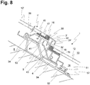
- FIG. 8 A further embodiment of a device 1 according to the invention is shown in FIG FIG. 8 shown in a longitudinal section analogous to FIG. 2 ,
- This variant differs from the embodiments of components FIG. 2 and 6 essentially by a different attachment of the panel 12, 12 'in the frame 11.
- the profiles 2, 2', 3, 4 of the frame 11 on a mounting surface 17 on which the panel is mounted.
- a spacer element 15 is fixed on the mounting surface 17, for example in the form of a plastic strip, for example by gluing.
- the panel 12 is attached, for example, also by gluing.
- the joint can be filled with a sealant such as a silicone sealant. The result is a watertight, substantially planar outer surface of the inventive element 11, on the water can flow easily. Ingress of water to the inside 14 is prevented by the seal 16.
- profiles of a certain depth h1 can easily be combined with panels of different thickness h2 to form components 1 according to the invention by selecting the thickness h3 of the spacers 15 such that the surface of the panel 2 is flush with the outer edge 30 of the lower profile 3. Since the panel 12 need not be threaded into a U-shaped groove of the frame 11, the frame 11 can be completely pre-assembled before the panel 12 has to be mounted. Components according to the invention can be manufactured so quickly and inexpensively, and an automated Production is easily possible. The attachment of the sealant is also better controllable than a U-profile.
Description
Die Erfindung betrifft ein Bauelement zur Verkleidung von Gebäuden, insbesondere von Schrägdächern oder Fassaden, gemäss dem Oberbegriff des unabhängigen Patentanspruchs.The invention relates to a component for covering buildings, in particular pitched roofs or facades, according to the preamble of the independent claim.
Sollen Dächer oder Fassaden von Gebäuden mit Photovoltaik-Modulen ausgerüstet werden, so können diese auf eine bestehende Fassade bzw. ein bestehendes Dach aufgesetzt werden, d.h. sie werden mit einer geeigneten, meist komplizierten Montagekonstruktion auf der Fassade oder der Dachhaut montiert. Die bestehende Dachhaut, beispielsweise eine Ziegeldach, kann weiter genutzt werden und die Photovoltaik-Module müssen keine Dichtungsfunktion übernehmen. Jedoch muss der Montageaufbau jeweils individuell auf ein bestimmtes Dach angepasst werden. Kostenmässig ist diese Methode vor allem bei bestehenden Dächern und Fassaden vorteilhaft.If roofs or facades of buildings are to be equipped with photovoltaic modules, they can be mounted on an existing façade or an existing roof, i. they are mounted on the façade or the roof with a suitable, usually complicated assembly construction. The existing roof skin, such as a tile roof, can continue to be used and the photovoltaic modules do not have to perform a sealing function. However, the assembly structure must be individually adapted to a particular roof. In terms of cost, this method is particularly advantageous for existing roofs and facades.
Alternativ können entsprechend ausgebildete Photovoltaik-Module selber die dichte Verkleidung des Dachs bzw. der Fassade bilden. Diese Möglichkeit ist vor allem bei neuen Gebäuden oder bei grösseren Renovationen vorteilhaft, da die Kosten für die Deckung des Dachs teilweise eingespart und so die gesamten Baukosten gesenkt werden können. Ein weiterer Vorteil einer solchen Lösung ist ein gleichmässigeres optisches Aussehen, und damit eine ästhetisch ansprechende Wirkung.Alternatively, appropriately designed photovoltaic modules themselves form the dense lining of the roof or the facade. This option is particularly advantageous for new buildings or larger renovations, since the cost of covering the roof can be partially saved and thus the total construction costs can be reduced. Another advantage of such a solution is a more uniform optical appearance, and thus an aesthetically pleasing effect.
Eine Bauweise mit seitlichen Rahmenprofilen, die ineinander greifen, hat den Vorteil, dass in Fallrichtung das unten liegende Profil eine Abflussrinne bildet, durch die das Regenwasser abfliessen kann. Jedoch hat diese Bauweise den Nachteil, dass das Verlegend der einzelnen Bauelemente zwingend in einer bestimmten waagrechten und senkrechten Reihenfolge erfolgen muss. Bei der Wartung beziehungsweise der Reparatur von einzelnen Bauelementen kann dies zu Problemen führen.A construction with side frame profiles that interlock, has the advantage that in the fall direction the profile below forms a drainage channel through which the rainwater can flow. However, this design has the disadvantage that the laying of the individual components must necessarily be made in a certain horizontal and vertical order. In the maintenance or repair of individual components, this can lead to problems.
Alle oben genannten Verkleidungs-Systeme weisen den Nachteil auf, dass die Bauelemente von unten nach oben verlegt werden müssen, um die notwendige Überlappung der einzelnen Bauelemente herstellen zu können. Bei einem Dach muss also von der Traufe zum First hin gedeckt werden. Zudem sind, im Gegensatz zu kleinformatigen, robusten Ziegeln, die grossformatigen Photovoltaik-Module schwer und nicht begehbar. Für einen Monteur ist die Verlegung solcher Bauelemente deshalb auch bei eher flachen Dächern sehr umständlich und mühsam. Vor allem bei grösseren Photovoltaik-Bauelementen können für die Montage sogar zwei Personen notwendig sein, was die Montagekosten erhöht.All the above-mentioned cladding systems have the disadvantage that the components must be laid from bottom to top to make the necessary overlap of the individual components can. For a roof, therefore, it must be covered from the eaves to the ridge. In addition, in contrast to small-sized, robust bricks, the large-format photovoltaic modules are heavy and not accessible. For a fitter, the laying of such components is therefore very cumbersome and tedious even with rather flat roofs. Especially with larger photovoltaic devices can be necessary for the assembly even two people, which increases the installation costs.
Eine Aufgabe der Erfindung ist es, ein Bauelement der eingangs erwähnten Art zur Verfügung zu stellen, insbesondere ein Photovoltaik-Bauelement, das die oben erwähnten und andere Nachteile nicht aufweist.An object of the invention is to provide a device of the type mentioned, in particular a photovoltaic device, which does not have the above-mentioned and other disadvantages.
Eine weitere Aufgabe der Erfindung ist es, ein Bauelement zur Verfügung zu stellen, welches es ermöglicht, ein Schrägdach oder eine Fassade von oben nach unten zu decken.Another object of the invention is to provide a component which makes it possible to cover a pitched roof or a facade from top to bottom.
Eine andere Aufgabe der Erfindung ist es, ein Bauelement zur Verfügung zu stellen, welches es ermöglicht, bei einer fertigen Gebäude-Verkleidung einzelne Bauelemente auszuwechseln, ohne dass andere Bauelemente entfernt werden müssen.Another object of the invention is to provide a component which makes it possible to replace individual components in a finished building cladding without having to remove other components.
Noch eine weitere Aufgabe der Erfindung ist es, ein Bauelement zur Verfügung zu stellen, das ohne zusätzliche, separate Dichtelemente aus Kunststoff aufkommt.Yet another object of the invention is to provide a component which is dispensed without additional, separate plastic sealing elements.
Ebenfalls eine Aufgabe der Erfindung ist es, ein Bauelement zur Verfügung zu stellen, welches von einer einzelnen Person montiert werden kann, selbst wenn es grössere Dimensionen hat. Die Arbeitssicherheit soll dabei höher sein als bei herkömmlichen Bauelementen.It is also an object of the invention to provide a component which can be mounted by a single person, even if it has larger dimensions. Occupational safety should be higher than with conventional components.
Eine weitere Aufgabe der Erfindung ist es, Bauelemente zur Verfügung zu stellen, mit welchem Dächer und Fassaden regendicht abgedeckt werden können, wobei ein möglichst geringer Materialverbrauch anfällt.Another object of the invention is to provide components with which roofs and facades can be covered rainproof, with the least possible material consumption.
Ein erfindungsgemässes Bauelement soll auch in kleineren Serien kostengünstig herstellbar sein.A device according to the invention should also be inexpensive to produce in smaller series.
Diese und andere Aufgaben werden gelöst durch ein erfindungsgemässes Bauelement gemäss Anspruch 1. Weitere bevorzugte Ausführungsformen sind in den abhängigen Ansprüchen gegeben.These and other objects are achieved by a device according to the invention according to
Ein erfindungsgemässes Bauelement gemäß Anspruch 1 ist vorgesehen zur regendichten Verkleidung einer Gebäudeaussenfläche, insbesondere eines Schrägdaches oder einer Fassade, mit einer Mehrzahl überlappender Bauelemente. Das Bauelement umfasst einen Rahmen und ein in oder auf diesem Rahmen befestigtes Paneel auf. Der Rahmen weist ein oberes Profil mit zwei oder mehr zur äusseren Witterungsseite hin ragenden Dichtlippen und ein unteres Profil mit zwei oder mehr von der Witterungsseite weg nach innen hin ragenden Dichtlippen auf. Die oberen beziehungsweise unteren Profile sind so ausgestaltet, dass sie mit einem unteren beziehungsweise oberen Profil eines benachbarten baugleichen Bauelements in Eingriff bringbar sind, so dass sich eine Labyrinthdichtung ergibt.An inventive component according to
Regendicht bedeutet in diesem Zusammenhang der beschriebenen Erfindung nicht absolut wasserdicht, sondern dicht gegen das Eindringen von Wasser aufgrund äusserer Witterungsseinflüsse, insbesondere Regen.Rainproof means in this context of the invention described not absolutely waterproof, but tight against the ingress of water due to external weather conditions, especially rain.
Vorzugsweise kommen die unteren und oberen Profile direkt benachbarter Bauelemente, insbesondere die Dichtlippen, nicht miteinander in Kontakt. Sie weisen ein stattdessen ein gewisses Spiel auf, so dass sich bei einer Längenausdehnung der Bauelemente aufgrund eines Temperaturwechsels keine mechanischen Spannungen aufbauen können. Dies ist bei Bauelementen mit Photovoltaik-Paneelen besonders wichtig, da sie sich aufgrund der dunklen Farbgebung besonders schnell erhitzen und abkühlen, so dass über den Verlauf eines Tages eine erhebliche Längenveränderung resultieren kann.Preferably, the lower and upper profiles of directly adjacent components, in particular the sealing lips, do not come into contact with each other. Instead, they have a certain amount of play, so that, given a thermal expansion of the components, no mechanical stresses can build up due to a temperature change. This is particularly important for components with photovoltaic panels, as they heat and cool very quickly due to the dark color, so that over the course of a day can result in a significant change in length.
Da keine weiteren dichtenden Elemente vorhanden sind, wie beispielsweise Kunststoffdichtungen, die unter den harschen Witterungsbedingungen auf einem Dach relativ schnell altern, müssen die Bauelemente nur sehr selten, wenn überhaupt, gewartet oder saniert werden.Since there are no other sealing elements, such as plastic gaskets, which age relatively quickly under the harsh weather conditions on a roof, the components rarely, if ever, have to be maintained or rehabilitated.
Das Paneel ist im Rahmen vorzugsweise dichtend gehalten. Das genannte Paneel kann ein Photovoltaikmodul sein, oder ein Sonnenkollektor-Modul zur Gewinnung von Warmwasser, oder aber auch eine einfache Abdeckung ohne weitere Funktion, beispielsweise aus Metallblech, Glas, oder transparentem Kunststoff.The panel is preferably kept sealed in the frame. Said panel may be a photovoltaic module, or a solar collector module for the production of hot water, or even a simple cover without additional function, such as sheet metal, glass, or transparent plastic.
Die Labyrinthdichtung, bei der die Dichtlippen der ineinander greifenden Profile abwechseln angeordnet sind, verhindert, dass in Fallrichtung über das Dach abfliessendes Wasser unter die Bauelemente gelangt. Es verhindert zudem auch effizient das Eindringen von Nebel oder Sprühwasser, und fängt Kondenswasser auf.The labyrinth seal, in which the sealing lips of the interlocking profiles are arranged alternately, prevents flowing in the direction of fall on the roof running water under the components. It also effectively prevents the ingress of mist or water spray, and captures condensation.
In dem erfindungsgemässen Bauelement ist das obere und das untere Profil des Rahmens derart ausgestaltet, dass das obere Profil durch eine Schwenkbewegung entlang einer Schwenkachse parallel zu einer oberen Kante des Bauelements mit einem unteren Profil eines oberhalb des Bauelements auf einer Unterkonstruktion montierten baugleichen Bauelements in Eingriff bringbar ist.In the inventive component, the upper and lower profile of the frame is designed such that the upper profile by a Pivoting movement along a pivot axis parallel to an upper edge of the component with a lower profile of an above the component mounted on a substructure identical component can be brought into engagement.
Derart ausgestaltete erfindungsgemässe Bauelemente können auf diese Weise von oben, vom First her, nach unten Richtung Traufe montiert werden, wobei bereits montierte Bauelemente nicht gelöst, verschoben oder angehoben werden müssen. Ein Monteur kann bei der Montage von unterhalb des bedeckten Daches arbeiten, und dabei eine vergleichsweise bequeme Haltung und einen sicheren Stand einnehmen. Es besteht zudem ein verringertes Risiko, bereits montierte Bauelemente versehentlich zu beschädigen.Such designed according to the invention components can be mounted in this way from above, from the ridge, down towards the eaves, with already assembled components must not be solved, moved or raised. An assembler can work from below the covered roof during installation, taking a comparatively comfortable posture and a secure footing. There is also a reduced risk of accidentally damaging already installed components.
Vorteilhaft weist der Rahmen eines ein erfindungsgemässen Bauelements zwei seitliche Profile auf, mit zwei oder mehr nach innen ragenden Dichtlippen.Advantageously, the frame of a component according to the invention has two lateral profiles, with two or more inwardly projecting sealing lips.
Das Paneel kann in einer U-förmigen Nut des Rahmens und/oder auf einer Montagefläche des Rahmens angeordnet sein.The panel may be disposed in a U-shaped groove of the frame and / or on a mounting surface of the frame.
Vorteilhaft bilden das Paneel und der Rahmen des Bauelements eine im wesentlichen wasserdichte Oberfläche.Advantageously, the panel and the frame of the device form a substantially watertight surface.
In einer Ausführungsform eines erfindungsgemässen Bauelements weist das obere Profil mindestens eine waagrechte Ablaufrinne auf.In one embodiment of a component according to the invention, the upper profile has at least one horizontal gutter.
Das Paneel eines erfindungsgemässen Bauelements kann beispielsweise ein Photovoltaik-Modul oder ein Sonnen-Kollektor-Modul sein.The panel of a device according to the invention may be, for example, a photovoltaic module or a solar collector module.
In einer anderen vorteilhaften Ausführungsform eines erfindungsgemässen Bauelements ist dieses Bauelement modular aus einzelnen, nach Bedarf kombinierbaren Teilen aufgebaut.In another advantageous embodiment of a device according to the invention, this component is constructed modularly from individual parts which can be combined as required.
Eine erfindungsgemässe Gebäudeverkleidung, insbesondere für ein Schrägdach, weist eine Mehrzahl von solchen erfindungsgemässen Bauelementen auf.An inventive building cladding, in particular for a pitched roof, has a plurality of such novel components.
Ein erfindungsgemässes Schrägdach und eine erfindungsgemässe Gebäudefassade weisen wie oder mehr erfindungsgemässe Bauelementen auf.A slanted roof according to the invention and a building facade according to the invention have as or more components according to the invention.
Eine erfindungsgemässe Energieerzeugungsanlage, insbesondere eine Photovoltaik-Anlage oder eine Sonnen-Kollektor-Anlage, weisen ein oder mehr erfindungsgemässe Bauelemente auf.A power generation plant according to the invention, in particular a photovoltaic plant or a solar collector plant, have one or more components according to the invention.
Bei dem erfindungsgemässen Verfahren gemäß Anspruchs 15 zur Herstellung eines Bauelements wird ein Rahmen mit einer umlaufenden Montagefläche bereitgestellt. Anschliessend wird ein Paneel auf der Montagefläche des Rahmens angeordnet, und zwischen einer Aussenkante und dem Rand des Paneels eine Dichtung angebracht. Die Dichtung bildet mit dem Rahmen und dem Paneel eine wasserdichte Oberfläche des Bauelements.In the method according to the invention according to claim 15 for the production of a component, a frame with a peripheral mounting surface is provided. Subsequently, a panel is placed on the mounting surface of the frame, and a seal is applied between an outer edge and the edge of the panel. The seal forms a watertight surface of the device with the frame and the panel.
Im Folgenden wird das erfindungsgemässe Bauelement anhand von Zeichnungen erläutert, die jedoch lediglich Ausführungsbeispiele zeigen.
Figur 1- zeigt in perspektivischer Ansicht eine mögliche Ausführungsform eines erfindungsgemässen Bauelements (das Tragelement ist nicht dargestellt).
Figur 2- zeigt in einem Längsschnitt in Fallrichtung den überlappenden Randbereich zweier erfindungsgemässer Bauelemente gemäss
Figur 1 , im fertig montierten Zustand. Figur 3- zeigt das erfindungsgemässe Bauelement aus
Figur 1 in einer Explosionsdarstellung. Figur 4- zeigt einen Querschnitt durch ein erfindungsgemässes Bauelement, mit zwei benachbarten Bauelementen.
Figur 5- zeigt im Längsschnitt die Montage eines erfindungsgemässen Bauelements unterhalb eines anderen Bauelements mittels einer Schwenkbewegung.
Figur 6- zeigt eine weitere Ausführungsform des erfindungsgemässen Bauelements, mit einem zusätzlichen Abstandshalter.
Figur 7- zeigt eine Aufsicht auf ein mit erfindungsgemässen Bauelementen bedecktes Dach.
Figur 8- zeigt noch eine weitere Ausführungsform des erfindungsgemässen Bauelements, mit einer alternativen Befestigung des Paneels im Rahmen.
- FIG. 1
- shows a perspective view of a possible embodiment of a device according to the invention (the support member is not shown).
- FIG. 2
- shows in a longitudinal section in the direction of fall the overlapping edge region of two components according to the invention
FIG. 1 , in ready assembled condition. - FIG. 3
- shows the inventive device
FIG. 1 in an exploded view. - FIG. 4
- shows a cross section through a device according to the invention, with two adjacent components.
- FIG. 5
- shows in longitudinal section the assembly of an inventive component below another component by means of a pivoting movement.
- FIG. 6
- shows a further embodiment of the inventive device, with an additional spacer.
- FIG. 7
- shows a plan view of a covered with inventive components roof.
- FIG. 8
- shows yet another embodiment of the inventive device, with an alternative attachment of the panel in the frame.
Die im Folgenden gegebenen Beispiele werden zur besseren Veranschaulichung der vorliegenden Erfindung gegeben, sind jedoch nicht dazu geeignet, die Erfindung auf die hierin offenbarten Merkmale zu beschränken.The examples given below are given for a better illustration of the present invention, but are not intended to limit the invention to the features disclosed herein.
Eine beispielhafte Ausführungsform eines erfindungsgemässen Bauelements 1 ist in
Der Aufbau des Rahmens aus einfachen Rahmenprofilen hat neben reduzierten Kosten auch den Vorteil, dass durch einfaches Ablängen der Profile sehr schnell der Rahmen für ein Paneel beliebiger Grösse gefertigt werden kann. Auf diese Weise können zum einen spezielle Dimensionierungswünsche ohne zusätzliche Kosten berücksichtigt werden, und zum anderen können zugekaufte Photovoltaik-Module sehr einfach in einem erfindungsgemässen Bauelement verbaut werden. Da zudem die Ecken des Bauelements im verbauten Zustand nicht einsehbar sind, kann auf aufwendige Eckabschlüsse verzichtet werden. Sollte zu einem späteren Zeitpunkt der Ersatz eines Bauelements notwendig werden, die entsprechenden Rahmenprofile aber nicht mehr zur Verfügung stehen, so kann auch das zu ersetzende Bauelement zerlegt, das Paneel ersetzt, und mit den alten Rahmenprofilen wieder zu einem neuen Bauelement zusammengefügt werden.The structure of the frame of simple frame profiles in addition to reduced costs and the advantage that can be made by simply cutting the profiles very quickly the frame for a panel of any size. In this way, on the one hand, special dimensioning requirements can be taken into account without additional costs, and on the other hand purchased photovoltaic modules can be very easily installed in a component according to the invention. In addition, since the corners of the device in the installed state are not visible, can be dispensed with complex corner finishes. Should the replacement of a component become necessary at a later date, but the corresponding frame profiles are no longer available, the component to be replaced can also be disassembled, the panel replaced, and the old frame profiles reassembled to form a new component.
Die Dimensionen des vergleichsweise klein dimensionierten Bauelements in
Die beiden seitlichen Profile 2, 2' weisen eine U-förmige Nut zur Aufnahme des Panels 12 sowie eine innere 22 und eine äussere 21 Dichtlippe auf. Die beiden Profile 2, 2' sind identisch, und unterscheiden sich lediglich in ihrer Ausrichtung im Bezug auf das Bauelement. Bei einem fertig montierten Bauelement verlaufen die seitlichen Profile in Fallrichtung. An einem oberen Ende des Bauelements 1 ist ein oberes Profil 4 angeordnet, mit zwei zur äusseren Seite des Bauelements gerichteten Dichtlippen 41, 42. Die äussere, am Rand gelegene Dichtlippe 41 schliesst dabei eine waagrechte Auffangrinne 43 ab, welche später das sich in der Labyrinthdichtung aufgefangene Kondenswasser und Sprühwasser zur Seite hin abführt.The two
Das an einem unteren Ende des Bauelements gelegene untere Profil 3 weist eine Abdeckung 37 auf, sowie zwei zur inneren Seite des Bauelements gerichtete Dichtlippen 31 und 32.The
Die äussere, am Rand gelegene Dichtlippe 41 kann auch kürzer sein als im dargestellten Beispiel, solange sichergestellt ist, dass die waagrechte Auffangrinne 43 Spritzwasser oder Kondenswasser auffangen kann, welches an der Dichtlippe 32' herab rinnt.The outer, located at the
Auf der Innenseite des Bauteils kann es auf der Rückseite des Paneels 12 zu Kondenswasserbildung kommen. Dieses läuft auf der Rückseite nach unten, ums schliesslich am unteren Ende in eine waagrechte Ablaufrinne 39 des unteren Profils 3' zu fliessen, von wo es zur Seite abgeführt wird.On the inside of the component may occur on the back of the
Je nach Aufbau der Rahmenprofile kann Wasser in den waagrechten Ablaufrinnen 43, 43a, 39 auf der Seite in den in Fallrichtung verlaufenden Ablaufkanal 8 abfliessen. Gegebenenfalls können auch Öffnungen im seitlichen Profil oder an den Längsenden der Ablaufrinnen 43, 43a, 39 vorhanden sein, durch die das gesammelte Wasser in den Ablaufkanal 8 abfliessen kann.Depending on the structure of the frame profiles, water in the
Im gezeigten Ausführungsbeispiel verläuft das untere Profil 3 über die gesamte Breite des Bauelements, während das obere Profil 4 von den beiden seitlichen Profilen 2, 2' flankiert wird. Alternativ kann auch das untere Profil zwischen den beiden seitlichen Profilen verlaufen, oder beide 3, 4 Profile über die gesamte Breite verlaufen. Andere Kombinationen sind ebenfalls denkbar, da die dichtende Wirkung in jedem Fall gegeben ist.In the embodiment shown, the
Das Dichtungsprinzip des erfindungsgemässen Bauelements wird insbesondere ersichtlich in
Das Tragelement 5 ist vorzugsweise aus Metall angefertigt. Dies hat neben Stabilitätsgründen den Vorteil, dass die Massen der Bauelemente elektrisch verbunden sind. Das Tragelement 5 kann alternativ auch einstückig als Teil des unteren Profils 3 geformt sein. Da bei einer Längenausdehnung des Bauelements das obere Profil 4 auf der zweiten Auflagefläche 52 gleitet, sollten die beiden Flächen möglichst glatt sein, um mechanische Spannungen zu vermeiden. Alternativ kann auch eine spezielle Gleitfläche, beispielsweise aus Polytetrafluoroethylen (Teflon) oder High-Density-Polyethylen vorgesehen sein.The
Ersichtlich sind auch die Schraublöcher 33, 44 in den Profilen 3', 4, mit denen die nicht dargestellten seitlichen Profile mit Schrauben mit den unteren und oberen Profilen 3, 4 verbunden werden. Die Paneele 12, 12' der beiden gezeigten Bauelemente sind in den U-förmigen Nuten 36, 46 der Profile 3', 4 gehalten. Die Silikondichtung zwischen Paneel und Nut ist nicht dargestellt. Bei Regen läuft nun das über das Dach abfliessendes Wasser über das Paneel 12' eines oberen Bauelements, von dort auf die Abdeckung 37 des unteren Profils 3', und über die äussere Dichtlippe 31' auf das Paneel 12 des unten liegenden Bauelements, usw.Also visible are the screw holes 33, 44 in the
Die sich vorzugsweise nicht berührenden Dichtlippen 31', 42, 32', 41 bilden eine Labyrinthdichtung 7, die den Luftaustausch zwischen aussen 13 und innen 14 und somit auch das Eindringen von Feuchtigkeit unter die Dachhaut minimiert. Labyrinthdichtungen sind per Definition nicht absolut gasdicht, sondern erhöhen den Fliesswiderstand eines Fluids, hier also der Luft, über ein gewünschtes Niveau, so dass der gewünschte relative Dichtungseffekt resultiert. Spritzwasser wird von der Labyrinthdichtung des erfindungsgemässen Bauteils ebenfalls erfolgreich zurückgehalten. Da der Abstand zwischen den beiden Profilen 3', 4 zwar gering, aber immer noch zu gross ist für einen Kapillareffekt, kann auch kein flüssiges Wasser entgegen der Schwerkraft unter die Dachhaut dringen. Das obere Profil 4 weist zwischen den beiden Dichtlippen waagrechte Auffangrinnen 43, 43a auf, welche gegebenenfalls trotzdem vorhandenes Wasser, z.B. aufgrund von kondensierter Feuchtigkeit, zur Seite hin wegleiten. Wichtig für die Betriebssicherheit einer Gebäudeverkleidung, insbesondere eines Daches, ist weiter, dass auch bei sehr starken Winden keine Luftströmung unter die Bauelemente gelangen kann, weil sonst das Dach durch den Wind zerstört werden kann. Aufgrund der engen Spaltbreite der Labyrinthdichtung ist dies jedoch auch bei direkter Anströmung mit sehr starken Winden nicht möglich. Zu diesem Zweck sind auch die äusseren Dichtlippen 21, 21' der seitlichen Profile 2, 2' an ihrem unteren Ende mit einer seitlichen Lippe versehen, welche die seitliche Abdichtung erhöht (vgl.
Im gezeigten Ausführungsbeispiel eines erfindungsgemässen Bauelements ist das Paneel 12 in den U-förmigen Nuten 26, 26', 36, 46 formschlüssig gehalten. Alternativ wäre es jedoch auch denkbar, dass Paneel mit dem Rahmen auf andere Weise zu verbinden, beispielsweise durch Verschrauben oder Verkleben.In the illustrated embodiment of a device according to the invention, the
Analog zur Labyrinthdichtung zwischen den oberen und unteren Profilen zweier in Fallrichtung benachbarter Bauelemente wird bei den seitlichen Profilen eine Labyrinthdichtung gebildet, wie aus dem Querschnitt in
Um erfindungsgemässe Bauelemente beim Decken eines Daches vom First her nach unten verlegen zu können, ist es notwendig, die Dichtlippen des oberen Profils unter die Dichtlippen des unteren Profils des bereits montierten Bauteils zu bringen. Dies kann beispielsweise durch seitliches Einfädeln bewerkstelligt werden, oder durch ein vorübergehendes Abheben des bereits montierten Bauteils vom Tragelement.In order to be able to install components according to the invention when covering a roof from the ridge downwards, it is necessary to bring the sealing lips of the upper profile under the sealing lips of the lower profile of the already mounted component. This can be accomplished, for example, by lateral threading, or by a temporary lifting of the already mounted component from the support element.
Bei einer bevorzugten Variante eines erfindungsgemässen Bauteils wird das obere Profil durch eine Schwenkbewegung des zu montierenden Bauteils unter das fixierte untere Profil gebracht. Das obere 4 und untere 3 Profil des Rahmens 11 sind dazu derart ausgestaltet, dass das obere Profil 4 durch eine Schwenkbewegung entlang einer Schwenkachse parallel zu einer oberen Kante des Bauelements mit dem unteren Profil 3' des oberhalb des Bauelements 1 auf der Unterkonstruktion 6 montierten baugleichen Bauelements 1' in Eingriff bringbar ist.In a preferred variant of an inventive component, the upper profile is brought by a pivoting movement of the component to be mounted under the fixed lower profile. The upper 4 and lower 3 profile of the
Der Ablauf des Montagevorgangs einer solchen bevorzugten Ausführungsform eines erfindungsgemässen Bauteils ist in
In einem dritten, abschliessenden Schritt,
Eine weitere Ausführungsform eines erfindungsgemässen Bauelements 1 ist in
Die in
Für den firstseitigen Abschluss und den unteren Abschluss einer Abdeckung mit erfindungsgemässen Bauelementen können verschiedene speziell modifizierte erfindungsgemässe Bauelemente vorgesehen sein.For the ridge-side termination and the lower termination of a cover with components according to the invention, various specially modified components according to the invention can be provided.
- 11
- Bauelementmodule
- 1111
- Rahmenframe
- 1212
- Paneelpaneling
- 1313
- Aussenseite des Bauelements, der Witterung zugewandtOutside of the device, facing the weather
- 1414
- Innenseite des Bauelements, der Witterung abgewandtInside of the component, facing away from the weather
- 1515
- Abstandshalterspacer
- 1616
- Dichtungpoetry
- 1717
- Montageflächemounting surface
- 2, 2'2, 2 '
- seitliches Profillateral profile
- 21, 21'21, 21 '
- innere Lippeinner lip
- 22, 22'22, 22 '
- äussere Lippeouter lip
- 2323
- Bohrlochwell
- 2424
- Zugriffsöffnungaccess opening
- 26, 26'26, 26 '
- U-förmige NutU-shaped groove
- 3, 3'3, 3 '
- unteres Profillower profile
- 3030
- Aussenkanteouter edge
- 31, 31'31, 31 '
- äussere Lippeouter lip
- 32, 32'32, 32 '
- innere Lippeinner lip
- 3333
- Schraublochscrew
- 3434
- Haltenutretaining groove
- 3535
- Einsatzcommitment
- 3636
- U-förmige NutU-shaped groove
- 3737
- Abdeckungcover
- 3838
- Druckschraubepressure screw
- 3939
- waagrechte Ablaufrinnehorizontal gutter
- 4, 4'4, 4 '
- oberes Profilupper profile
- 4141
- äussere Lippeouter lip
- 4242
- innere Lippeinner lip
- 43, 43a43, 43a
- waagrechte Auffangrinnehorizontal gutter
- 4444
- Schraublochscrew
- 4545
- Einsatzcommitment
- 4646
- U-förmige NutU-shaped groove
- 55
- Tragelementsupporting member
- 5151
- Abstandshalterspacer
- 5252
- Befestigungsmittelfastener
- 5353
- erste Auflageflächefirst contact surface
- 5454
- zweite Auflageflächesecond bearing surface
- 66
- Unterkonstruktion, DachlatteSubstructure, batten
- 77
- Labyrinthdichtunglabyrinth seal
- 88th
- Abflusskanalspillway
- 8181
- innere Rinneinner gutter
- 8282
- äussere Rinneouter gutter
- 99
- Schwenkbewegungpivotal movement
- h1h1
- Tiefe des ProfilsDepth of the profile
- h2h2
- Dicke des PaneelsThickness of the panel
- h3h3
- Dicke des AbstandselementsThickness of the spacer
Claims (15)
- Structural element (1) with a supporting element (5) for fixing the structural element (1) on a substructure (6) for the rainproof cladding of an exterior building surface, in particular of a pitched roof or of a façade, having a plurality of overlapping structural elements (1, 1'), wherein the structural element (1) has a frame (11) and a panel (12), which is fastened in or on said frame, and the frame (11) has an upper profile (4), with two or more sealing lips (41, 42) projecting in the direction of the exterior, weather-facing side (13), and a lower profile (3), with two or more sealing lips (31, 32) projecting inwards (14) away from the weather-facing side (13), said profiles being configured such that they can be brought into engagement with a lower profile (3') and an upper profile (4'), respectively, of an adjacent identical structural element (1'), this resulting in the formation of a labyrinth seal (7),
characterized in that
the supporting element (5) has a first contact area (53), which is provided in the form of a contact area for the lower profile (3) of the structural element (1), and a second contact area (54), which is provided in the form of a contact area for the upper profile (4') of an adjacent identical structural element (1'), and
in that
the upper profile (4) and lower profile (3) of the frame (11) are configured such that, by virtue of being pivoted along a pivot axis parallel to an upper edge of the structural element, the upper profile (4) can be brought into engagement with a lower profile (3') of an identical structural element (1') installed above the structural element (1) on the substructure (6). - Structural element according to Claim 1, characterized in that the lower and upper profiles (3, 4', 3', 4) of two adjacent structural elements (1, 1') cannot come into direct contact.
- Structural element according to Claim 1 or 2, characterized in that the supporting element (5) is, or can be, connected to the lower profile (3) in a releasable or non-releasable manner.
- Structural element according to Claim 3, characterized in that the lower profile (3) has a retaining groove (34) for form-fitting connection to a projecting region of the first contact area (53) .
- Structural element according to one of the preceding claims, characterized in that the supporting element (5) has a lip provided to fit a spacer (51).
- Structural element according to one of the preceding claims, characterized in that the panel (12) is arranged in a U-shaped groove (26, 26', 36, 46) of the frame (11).
- Structural element according to one of the preceding claims, characterized in that the panel (12) is arranged on an installation surface (17) of the frame (11).
- Structural element according to one of the preceding claims, characterized in that the upper profile (4) has at least one horizontal drainage channel (43, 43a).
- Structural element according to one of the preceding claims, characterized in that the panel (12) is a photovoltaic module or a solar collector module.
- Structural element according to one of the preceding claims, characterized in that the structural element (1) is constructed in modular fashion from individual parts (2, 2', 3, 4, 12) which can be combined as required.
- Building cladding, in particular for a pitched roof, having a plurality of structural elements (1) according to one of Claims 1 to 10.
- Pitched roof having two or more structural elements (1) according to one of Claims 1 to 10.
- Building façade having two or more structural elements (1) according to one of Claims 1 to 10.
- Power-generating plant, in particular a photovoltaic power plant or a solar collector plant, having one or more structural elements (1) according to one of Claims 1 to 10.
- Method for producing a structural element (1) according to one of Claims 1 to 10, having a frame (11) with profiles (2, 2', 3, 4) of a certain depth (h1) and a panel (12) of a certain thickness (h2), for the rainproof cladding of an exterior building surface, characterized in that the frame (11) is supplied with a circumferential installation surface (17), spacer elements (15) of a thickness (h3) are fastened on the installation surface (17), the panel (12) is fastened on the spacer elements (15), and a seal (16) is fitted between an outer edge (30) and the periphery of the panel (12), said seal forming, along with the frame (11) and the panel (12), a water-tight surface of the structural element (1), wherein the thickness (h3) of the spacer elements (15) is selected such that the surface of the panel (2) is flush with the outer edge (30) of the lower profile (3) of the frame (11) .
Applications Claiming Priority (1)
| Application Number | Priority Date | Filing Date | Title |
|---|---|---|---|
| CH01938/08A CH700095B1 (en) | 2008-12-09 | 2008-12-09 | Component for cladding buildings. |
Publications (2)
| Publication Number | Publication Date |
|---|---|
| EP2196594A1 EP2196594A1 (en) | 2010-06-16 |
| EP2196594B1 true EP2196594B1 (en) | 2019-04-24 |
Family
ID=42041679
Family Applications (1)
| Application Number | Title | Priority Date | Filing Date |
|---|---|---|---|
| EP09178519.6A Active EP2196594B1 (en) | 2008-12-09 | 2009-12-09 | Element for cladding buildings |
Country Status (2)
| Country | Link |
|---|---|
| EP (1) | EP2196594B1 (en) |
| CH (1) | CH700095B1 (en) |
Families Citing this family (44)
| Publication number | Priority date | Publication date | Assignee | Title |
|---|---|---|---|---|
| FR2963801A1 (en) * | 2010-08-16 | 2012-02-17 | Solframe | MODULAR DEVICE FOR ENSURING THE COVERAGE OF A SURFACE SUCH AS THE ROOF OF A BUILDING AND THE PRODUCTION OF ELECTRICITY |
| FR2967433A1 (en) * | 2010-11-15 | 2012-05-18 | Harmony Air Conditioning | Device for fixing photovoltaic panels on carcass of roof of house, has locking elements mounted on fixation frames and associated with sealing elements that assure sealing between photovoltaic panels received by housings of frames |
| FR2967704A1 (en) * | 2010-11-22 | 2012-05-25 | Abcd Internat | Solar panels integration device for roof of building, has two parallel rails including fixing grooves delimited by two lateral vertical walls, where fixing grooves fix ends of sleepers on rails |
| ITAN20110002A1 (en) * | 2011-01-17 | 2012-07-18 | Energy Resources S P A | SYSTEM FOR SUPPORT AND FIXING WITH WATERPROOF OVERHEATING FOR FLAT PANELS OR PHOTOVOLTAIC MODULES |
| FR2970989B1 (en) * | 2011-02-01 | 2013-02-15 | Lm Ind | SUPPORT DEVICE FOR PHOTOVOLTAIC ROOF PANELS, ANTI-THEFT |
| CH705036A1 (en) | 2011-05-27 | 2012-11-30 | Markus Gisler | A cladding system for cladding a building outside surface. |
| ITRM20110362A1 (en) * | 2011-07-12 | 2013-01-13 | Mauro Pula | INTEGRATED SYSTEM OF PANELS, PREFERABLY PHOTOVOLTAIC. |
| FR2979365B1 (en) * | 2011-08-31 | 2015-04-03 | Integrasol | DEVICE FOR INTEGRATING AND FIXING A PHOTOVOLTAIC PANEL TO A ROOF. |
| AT512032B1 (en) * | 2011-12-12 | 2013-05-15 | Lenz Bernhard | ARRANGEMENT FOR FIXING PLATES |
| DE102011122340A1 (en) * | 2011-12-23 | 2013-06-27 | Centrotherm Photovoltaics Ag | Photovoltaic system has photovoltaic modules which are attached to primary and/or secondary channel elements, and adjacent channel elements are partially overlapped with primary and secondary channel elements to form closed structure |
| EP2617914A1 (en) * | 2012-01-19 | 2013-07-24 | Josef Rupp | Roof slab and roof covering system |
| EP2662644A1 (en) * | 2012-05-09 | 2013-11-13 | C-Lean S.r.l. | Installation assembly of photovoltaic panels |
| DE202012102087U1 (en) * | 2012-06-06 | 2012-10-05 | Enrico Folta | Solar module holder for mounting PV modules as in-roof modules |
| EP2679929A1 (en) | 2012-06-26 | 2014-01-01 | Centrosolar AG | Assembly and seal system for installing a number of board-shaped modules in an inclined roof |
| GB201605135D0 (en) * | 2016-03-25 | 2016-05-11 | Estill Ewen | Solar panel mounting |
| TWI679388B (en) * | 2018-04-20 | 2019-12-11 | 王家壽 | Solar panel frame group |
| US11012024B2 (en) * | 2018-07-03 | 2021-05-18 | Building Materials Investment Corporation | Roof integrated photovoltaic system with improved serviceability |
| US11398795B2 (en) | 2019-12-20 | 2022-07-26 | GAF Energy LLC | Roof integrated photovoltaic system |
| US11489482B2 (en) | 2020-01-22 | 2022-11-01 | GAF Energy LLC | Integrated photovoltaic roofing shingles, methods, systems, and kits thereof |
| US11283394B2 (en) | 2020-02-18 | 2022-03-22 | GAF Energy LLC | Photovoltaic module with textured superstrate providing shingle-mimicking appearance |
| US11431281B2 (en) | 2020-02-27 | 2022-08-30 | GAF Energy LLC | Photovoltaic module with light-scattering encapsulant providing shingle-mimicking appearance |
| MX2022012640A (en) | 2020-04-09 | 2023-01-11 | GAF Energy LLC | Three-dimensional laminate photovoltaic module. |
| CN115812034A (en) | 2020-04-30 | 2023-03-17 | Gaf能源有限责任公司 | Photovoltaic module front and back sheets |
| EP4150726A1 (en) | 2020-05-13 | 2023-03-22 | Gaf Energy LLC | Electrical cable passthrough |
| CA3180900A1 (en) | 2020-06-04 | 2021-12-09 | Gabriela Bunea | Photovoltaic shingles and methods of installing same |
| US11843067B2 (en) | 2020-07-22 | 2023-12-12 | GAF Energy LLC | Photovoltaic modules |
| MX2023002696A (en) | 2020-09-03 | 2023-05-24 | GAF Energy LLC | Building integrated photovoltaic system. |
| US11545928B2 (en) | 2020-10-13 | 2023-01-03 | GAF Energy LLC | Solar roofing system |
| CA3195662A1 (en) | 2020-10-14 | 2022-04-21 | Peter Clemente | Mounting apparatus for photovoltaic modules |
| WO2022094049A1 (en) | 2020-10-29 | 2022-05-05 | GAF Energy LLC | System of roofing and photovoltaic shingles and methods of installing same |
| WO2022103968A1 (en) | 2020-11-12 | 2022-05-19 | GAF Energy LLC | Roofing shingles with handles |
| CA3197598A1 (en) | 2020-11-13 | 2022-05-19 | Gabriela Bunea | Photovoltaic module systems and methods |
| WO2022159478A1 (en) | 2021-01-19 | 2022-07-28 | GAF Energy LLC | Watershedding features for roofing shingles |
| EP4295414A1 (en) | 2021-02-19 | 2023-12-27 | Gaf Energy LLC | Photovoltaic module for a roof with continuous fiber tape |
| US11527665B2 (en) | 2021-05-06 | 2022-12-13 | GAF Energy LLC | Photovoltaic module with transparent perimeter edges |
| WO2022256430A1 (en) | 2021-06-02 | 2022-12-08 | GAF Energy LLC | Photovoltaic module with light-scattering encapsulant providing shingle-mimicking appearance |
| WO2022259054A1 (en) * | 2021-06-12 | 2022-12-15 | Arka Energy Inc. | Assembly for mounting tiles over a surface |
| WO2022268398A1 (en) * | 2021-06-25 | 2022-12-29 | Paxos Consulting & Engineering GmbH & Co. KG | Solar roof tile and method for producing a solar roof tile |
| DE112022003254A5 (en) * | 2021-06-25 | 2024-04-04 | Paxos Consulting & Engineering GmbH & Co. KG | Solar roof tile, roof with solar roof tile, method for assembling and disassembling a solar roof tile |
| US11512480B1 (en) | 2021-07-16 | 2022-11-29 | GAF Energy LLC | Roof material storage bracket |
| WO2023034432A1 (en) | 2021-09-01 | 2023-03-09 | GAF Energy LLC | Photovoltaic modules for commercial roofing |
| CN114704032A (en) * | 2022-01-06 | 2022-07-05 | 江苏通灵电器股份有限公司 | Novel roof integration photovoltaic distribution structure and roof integration photovoltaic power plant |
| WO2023141566A1 (en) | 2022-01-20 | 2023-07-27 | GAF Energy LLC | Roofing shingles for mimicking the appearance of photovoltaic modules |
| US11811361B1 (en) | 2022-12-14 | 2023-11-07 | GAF Energy LLC | Rapid shutdown device for photovoltaic modules |
Family Cites Families (2)
| Publication number | Priority date | Publication date | Assignee | Title |
|---|---|---|---|---|
| FR2465315A1 (en) * | 1979-09-10 | 1981-03-20 | Radiotechnique Compelec | PHOTOVOLTAIC GENERATING PANEL ASSURING THE SEALING IN THE INTEMPERIES OF A ROOF BY DIRECT INSTALLATION ON THE FRAMEWORK |
| CH684202A5 (en) * | 1991-07-11 | 1994-07-29 | Plaston Ag Kunststoffwerk Hans | Roof covering and structural element with solar cells |
-
2008
- 2008-12-09 CH CH01938/08A patent/CH700095B1/en unknown
-
2009
- 2009-12-09 EP EP09178519.6A patent/EP2196594B1/en active Active
Non-Patent Citations (1)
| Title |
|---|
| None * |
Also Published As
| Publication number | Publication date |
|---|---|
| CH700095B1 (en) | 2012-09-14 |
| CH700095A2 (en) | 2010-06-15 |
| EP2196594A1 (en) | 2010-06-16 |
Similar Documents
| Publication | Publication Date | Title |
|---|---|---|
| EP2196594B1 (en) | Element for cladding buildings | |
| EP2784241B1 (en) | Roof covering for utilising solar energy | |
| EP1703037B1 (en) | Roof or wall covering | |
| EP1734588B1 (en) | Roofing system | |
| EP2238392B1 (en) | Fastening system for a plate-shaped structural element | |
| EP2381188A2 (en) | Solar module assembly system and building cladding | |
| EP1362967A1 (en) | Device with flat, panel shaped building elements | |
| EP2234174A2 (en) | Roof covering system for solar modules | |
| DE202011109727U1 (en) | Arrangement for fixing plate elements | |
| WO2013056769A1 (en) | Profiled elements for an in-roof solar system arrangement | |
| EP2527763B1 (en) | Cladding system for cladding the external surface of a building | |
| EP2679929A1 (en) | Assembly and seal system for installing a number of board-shaped modules in an inclined roof | |
| EP2541618A1 (en) | In-roof solar system assembly | |
| AT403181B (en) | METHOD FOR KEEPING RAINWATER DRAINS FROM A ROOF FROM ICE FORMATION, AND DEVICE FOR CARRYING OUT THIS METHOD | |
| AT523015B1 (en) | Frame of a module for a modular photovoltaic system, module made therewith and modular photovoltaic system | |
| EP0960990B1 (en) | Device for covering an inclined roof surface | |
| DE102010034841B4 (en) | Roof panel and roofing system | |
| DE10309445B3 (en) | Frame system for roof components especially solar energy panels and windows has a base and connectible bonding sections having substrate shaped profiles | |
| DE202010008139U1 (en) | roofing | |
| DE2848946A1 (en) | Prefabricated roofing units with solar energy provision - are made from shaped sheet metal or plastics for easily laid components | |
| DE102011051283A1 (en) | Roof-element for forming pitched-roof to cover building, has profile frame connectable at periphery of solar module in rainwater-proof manner, where module is arranged at distance to bottom plate form cavity between plate and module | |
| EP2617914A1 (en) | Roof slab and roof covering system | |
| DE4434879C1 (en) | Extruded aluminium@ roofing | |
| DE102008022153A1 (en) | Device for fixing photovoltaic modules | |
| DE19606442C1 (en) | Plastics or aluminium@ roofing |
Legal Events
| Date | Code | Title | Description |
|---|---|---|---|
| PUAI | Public reference made under article 153(3) epc to a published international application that has entered the european phase |
Free format text: ORIGINAL CODE: 0009012 |
|
| AK | Designated contracting states |
Kind code of ref document: A1 Designated state(s): AT BE BG CH CY CZ DE DK EE ES FI FR GB GR HR HU IE IS IT LI LT LU LV MC MK MT NL NO PL PT RO SE SI SK SM TR |
|
| AX | Request for extension of the european patent |
Extension state: AL BA RS |
|
| 17P | Request for examination filed |
Effective date: 20101028 |
|
| 17Q | First examination report despatched |
Effective date: 20101126 |
|
| RIC1 | Information provided on ipc code assigned before grant |
Ipc: E04D 3/02 20060101ALI20111019BHEP Ipc: F24J 2/04 20060101AFI20111019BHEP Ipc: H01L 31/042 20060101ALI20111019BHEP Ipc: F24J 2/52 20060101ALI20111019BHEP Ipc: H01L 31/048 20060101ALI20111019BHEP |
|
| REG | Reference to a national code |
Ref country code: DE Ref legal event code: R079 Ref document number: 502009015728 Country of ref document: DE Free format text: PREVIOUS MAIN CLASS: E04D0003020000 Ipc: H01L0031042000 |
|
| GRAP | Despatch of communication of intention to grant a patent |
Free format text: ORIGINAL CODE: EPIDOSNIGR1 |
|
| STAA | Information on the status of an ep patent application or granted ep patent |
Free format text: STATUS: GRANT OF PATENT IS INTENDED |
|
| RIC1 | Information provided on ipc code assigned before grant |
Ipc: E04D 3/02 20060101ALI20180928BHEP Ipc: F24S 20/00 20180101ALI20180928BHEP Ipc: H01L 31/042 20060101AFI20180928BHEP Ipc: H01L 31/048 20060101ALI20180928BHEP |
|
| INTG | Intention to grant announced |
Effective date: 20181018 |
|
| RIC1 | Information provided on ipc code assigned before grant |
Ipc: H01L 31/042 20140101AFI20180928BHEP Ipc: F24S 20/00 20180101ALI20180928BHEP Ipc: E04D 3/02 20060101ALI20180928BHEP Ipc: H01L 31/048 20140101ALI20180928BHEP |
|
| GRAS | Grant fee paid |
Free format text: ORIGINAL CODE: EPIDOSNIGR3 |
|
| GRAJ | Information related to disapproval of communication of intention to grant by the applicant or resumption of examination proceedings by the epo deleted |
Free format text: ORIGINAL CODE: EPIDOSDIGR1 |
|
| GRAL | Information related to payment of fee for publishing/printing deleted |
Free format text: ORIGINAL CODE: EPIDOSDIGR3 |
|
| STAA | Information on the status of an ep patent application or granted ep patent |
Free format text: STATUS: EXAMINATION IS IN PROGRESS |
|
| GRAR | Information related to intention to grant a patent recorded |
Free format text: ORIGINAL CODE: EPIDOSNIGR71 |
|
| STAA | Information on the status of an ep patent application or granted ep patent |
Free format text: STATUS: GRANT OF PATENT IS INTENDED |
|
| GRAA | (expected) grant |
Free format text: ORIGINAL CODE: 0009210 |
|
| STAA | Information on the status of an ep patent application or granted ep patent |
Free format text: STATUS: THE PATENT HAS BEEN GRANTED |
|
| INTC | Intention to grant announced (deleted) | ||
| AK | Designated contracting states |
Kind code of ref document: B1 Designated state(s): AT BE BG CH CY CZ DE DK EE ES FI FR GB GR HR HU IE IS IT LI LT LU LV MC MK MT NL NO PL PT RO SE SI SK SM TR |
|
| INTG | Intention to grant announced |
Effective date: 20190319 |
|
| REG | Reference to a national code |
Ref country code: GB Ref legal event code: FG4D Free format text: NOT ENGLISH |
|
| REG | Reference to a national code |
Ref country code: CH Ref legal event code: EP |
|
| REG | Reference to a national code |
Ref country code: AT Ref legal event code: REF Ref document number: 1125166 Country of ref document: AT Kind code of ref document: T Effective date: 20190515 Ref country code: IE Ref legal event code: FG4D Free format text: LANGUAGE OF EP DOCUMENT: GERMAN |
|
| REG | Reference to a national code |
Ref country code: DE Ref legal event code: R096 Ref document number: 502009015728 Country of ref document: DE |
|
| REG | Reference to a national code |
Ref country code: CH Ref legal event code: NV Representative=s name: RENTSCH PARTNER AG, CH |
|
| REG | Reference to a national code |
Ref country code: NL Ref legal event code: MP Effective date: 20190424 |
|
| REG | Reference to a national code |
Ref country code: LT Ref legal event code: MG4D |
|
| PG25 | Lapsed in a contracting state [announced via postgrant information from national office to epo] |
Ref country code: NL Free format text: LAPSE BECAUSE OF FAILURE TO SUBMIT A TRANSLATION OF THE DESCRIPTION OR TO PAY THE FEE WITHIN THE PRESCRIBED TIME-LIMIT Effective date: 20190424 |
|
| PG25 | Lapsed in a contracting state [announced via postgrant information from national office to epo] |
Ref country code: ES Free format text: LAPSE BECAUSE OF FAILURE TO SUBMIT A TRANSLATION OF THE DESCRIPTION OR TO PAY THE FEE WITHIN THE PRESCRIBED TIME-LIMIT Effective date: 20190424 Ref country code: SE Free format text: LAPSE BECAUSE OF FAILURE TO SUBMIT A TRANSLATION OF THE DESCRIPTION OR TO PAY THE FEE WITHIN THE PRESCRIBED TIME-LIMIT Effective date: 20190424 Ref country code: PT Free format text: LAPSE BECAUSE OF FAILURE TO SUBMIT A TRANSLATION OF THE DESCRIPTION OR TO PAY THE FEE WITHIN THE PRESCRIBED TIME-LIMIT Effective date: 20190824 Ref country code: HR Free format text: LAPSE BECAUSE OF FAILURE TO SUBMIT A TRANSLATION OF THE DESCRIPTION OR TO PAY THE FEE WITHIN THE PRESCRIBED TIME-LIMIT Effective date: 20190424 Ref country code: LT Free format text: LAPSE BECAUSE OF FAILURE TO SUBMIT A TRANSLATION OF THE DESCRIPTION OR TO PAY THE FEE WITHIN THE PRESCRIBED TIME-LIMIT Effective date: 20190424 Ref country code: FI Free format text: LAPSE BECAUSE OF FAILURE TO SUBMIT A TRANSLATION OF THE DESCRIPTION OR TO PAY THE FEE WITHIN THE PRESCRIBED TIME-LIMIT Effective date: 20190424 Ref country code: NO Free format text: LAPSE BECAUSE OF FAILURE TO SUBMIT A TRANSLATION OF THE DESCRIPTION OR TO PAY THE FEE WITHIN THE PRESCRIBED TIME-LIMIT Effective date: 20190724 |
|
| PG25 | Lapsed in a contracting state [announced via postgrant information from national office to epo] |
Ref country code: PL Free format text: LAPSE BECAUSE OF FAILURE TO SUBMIT A TRANSLATION OF THE DESCRIPTION OR TO PAY THE FEE WITHIN THE PRESCRIBED TIME-LIMIT Effective date: 20190424 Ref country code: BG Free format text: LAPSE BECAUSE OF FAILURE TO SUBMIT A TRANSLATION OF THE DESCRIPTION OR TO PAY THE FEE WITHIN THE PRESCRIBED TIME-LIMIT Effective date: 20190724 Ref country code: GR Free format text: LAPSE BECAUSE OF FAILURE TO SUBMIT A TRANSLATION OF THE DESCRIPTION OR TO PAY THE FEE WITHIN THE PRESCRIBED TIME-LIMIT Effective date: 20190725 Ref country code: LV Free format text: LAPSE BECAUSE OF FAILURE TO SUBMIT A TRANSLATION OF THE DESCRIPTION OR TO PAY THE FEE WITHIN THE PRESCRIBED TIME-LIMIT Effective date: 20190424 |
|
| PG25 | Lapsed in a contracting state [announced via postgrant information from national office to epo] |
Ref country code: IS Free format text: LAPSE BECAUSE OF FAILURE TO SUBMIT A TRANSLATION OF THE DESCRIPTION OR TO PAY THE FEE WITHIN THE PRESCRIBED TIME-LIMIT Effective date: 20190824 |
|
| REG | Reference to a national code |
Ref country code: DE Ref legal event code: R097 Ref document number: 502009015728 Country of ref document: DE |
|
| PG25 | Lapsed in a contracting state [announced via postgrant information from national office to epo] |
Ref country code: DK Free format text: LAPSE BECAUSE OF FAILURE TO SUBMIT A TRANSLATION OF THE DESCRIPTION OR TO PAY THE FEE WITHIN THE PRESCRIBED TIME-LIMIT Effective date: 20190424 Ref country code: SK Free format text: LAPSE BECAUSE OF FAILURE TO SUBMIT A TRANSLATION OF THE DESCRIPTION OR TO PAY THE FEE WITHIN THE PRESCRIBED TIME-LIMIT Effective date: 20190424 Ref country code: RO Free format text: LAPSE BECAUSE OF FAILURE TO SUBMIT A TRANSLATION OF THE DESCRIPTION OR TO PAY THE FEE WITHIN THE PRESCRIBED TIME-LIMIT Effective date: 20190424 Ref country code: CZ Free format text: LAPSE BECAUSE OF FAILURE TO SUBMIT A TRANSLATION OF THE DESCRIPTION OR TO PAY THE FEE WITHIN THE PRESCRIBED TIME-LIMIT Effective date: 20190424 Ref country code: EE Free format text: LAPSE BECAUSE OF FAILURE TO SUBMIT A TRANSLATION OF THE DESCRIPTION OR TO PAY THE FEE WITHIN THE PRESCRIBED TIME-LIMIT Effective date: 20190424 |
|
| PG25 | Lapsed in a contracting state [announced via postgrant information from national office to epo] |
Ref country code: SM Free format text: LAPSE BECAUSE OF FAILURE TO SUBMIT A TRANSLATION OF THE DESCRIPTION OR TO PAY THE FEE WITHIN THE PRESCRIBED TIME-LIMIT Effective date: 20190424 Ref country code: IT Free format text: LAPSE BECAUSE OF FAILURE TO SUBMIT A TRANSLATION OF THE DESCRIPTION OR TO PAY THE FEE WITHIN THE PRESCRIBED TIME-LIMIT Effective date: 20190424 |
|
| PLBE | No opposition filed within time limit |
Free format text: ORIGINAL CODE: 0009261 |
|
| STAA | Information on the status of an ep patent application or granted ep patent |
Free format text: STATUS: NO OPPOSITION FILED WITHIN TIME LIMIT |
|
| PG25 | Lapsed in a contracting state [announced via postgrant information from national office to epo] |
Ref country code: TR Free format text: LAPSE BECAUSE OF FAILURE TO SUBMIT A TRANSLATION OF THE DESCRIPTION OR TO PAY THE FEE WITHIN THE PRESCRIBED TIME-LIMIT Effective date: 20190424 |
|
| 26N | No opposition filed |
Effective date: 20200127 |
|
| PG25 | Lapsed in a contracting state [announced via postgrant information from national office to epo] |
Ref country code: SI Free format text: LAPSE BECAUSE OF FAILURE TO SUBMIT A TRANSLATION OF THE DESCRIPTION OR TO PAY THE FEE WITHIN THE PRESCRIBED TIME-LIMIT Effective date: 20190424 |
|
| PG25 | Lapsed in a contracting state [announced via postgrant information from national office to epo] |
Ref country code: MC Free format text: LAPSE BECAUSE OF FAILURE TO SUBMIT A TRANSLATION OF THE DESCRIPTION OR TO PAY THE FEE WITHIN THE PRESCRIBED TIME-LIMIT Effective date: 20190424 |
|
| PG25 | Lapsed in a contracting state [announced via postgrant information from national office to epo] |
Ref country code: IE Free format text: LAPSE BECAUSE OF NON-PAYMENT OF DUE FEES Effective date: 20191209 Ref country code: LU Free format text: LAPSE BECAUSE OF NON-PAYMENT OF DUE FEES Effective date: 20191209 |
|
| PG25 | Lapsed in a contracting state [announced via postgrant information from national office to epo] |
Ref country code: CY Free format text: LAPSE BECAUSE OF FAILURE TO SUBMIT A TRANSLATION OF THE DESCRIPTION OR TO PAY THE FEE WITHIN THE PRESCRIBED TIME-LIMIT Effective date: 20190424 |
|
| PG25 | Lapsed in a contracting state [announced via postgrant information from national office to epo] |
Ref country code: HU Free format text: LAPSE BECAUSE OF FAILURE TO SUBMIT A TRANSLATION OF THE DESCRIPTION OR TO PAY THE FEE WITHIN THE PRESCRIBED TIME-LIMIT; INVALID AB INITIO Effective date: 20091209 Ref country code: MT Free format text: LAPSE BECAUSE OF FAILURE TO SUBMIT A TRANSLATION OF THE DESCRIPTION OR TO PAY THE FEE WITHIN THE PRESCRIBED TIME-LIMIT Effective date: 20190424 |
|
| PG25 | Lapsed in a contracting state [announced via postgrant information from national office to epo] |
Ref country code: MK Free format text: LAPSE BECAUSE OF FAILURE TO SUBMIT A TRANSLATION OF THE DESCRIPTION OR TO PAY THE FEE WITHIN THE PRESCRIBED TIME-LIMIT Effective date: 20190424 |
|
| REG | Reference to a national code |
Ref country code: DE Ref legal event code: R081 Ref document number: 502009015728 Country of ref document: DE Owner name: MEGASOL ENERGIE AG, CH Free format text: FORMER OWNER: GISLER, MARKUS, NIEDERBIPP, CH Ref country code: DE Ref legal event code: R082 Ref document number: 502009015728 Country of ref document: DE Representative=s name: MUELLER HOFFMANN & PARTNER PATENTANWAELTE MBB, DE |
|
| REG | Reference to a national code |
Ref country code: GB Ref legal event code: 732E Free format text: REGISTERED BETWEEN 20220915 AND 20220921 |
|
| PGFP | Annual fee paid to national office [announced via postgrant information from national office to epo] |
Ref country code: BE Payment date: 20221221 Year of fee payment: 14 |
|
| REG | Reference to a national code |
Ref country code: AT Ref legal event code: PC Ref document number: 1125166 Country of ref document: AT Kind code of ref document: T Owner name: MEGASOL ENERGIE AG, CH Effective date: 20230228 |
|
| PGFP | Annual fee paid to national office [announced via postgrant information from national office to epo] |
Ref country code: CH Payment date: 20221213 Year of fee payment: 14 |
|
| REG | Reference to a national code |
Ref country code: BE Ref legal event code: PD Owner name: MEGASOL ENERGIE AG; CH Free format text: DETAILS ASSIGNMENT: CHANGE OF OWNER(S), ASSIGNMENT; FORMER OWNER NAME: GISLER, MARKUS Effective date: 20230320 |
|
| PGFP | Annual fee paid to national office [announced via postgrant information from national office to epo] |
Ref country code: GB Payment date: 20231220 Year of fee payment: 15 |
|
| PGFP | Annual fee paid to national office [announced via postgrant information from national office to epo] |
Ref country code: FR Payment date: 20231221 Year of fee payment: 15 Ref country code: DE Payment date: 20231214 Year of fee payment: 15 Ref country code: AT Payment date: 20231221 Year of fee payment: 15 |
|
| PGFP | Annual fee paid to national office [announced via postgrant information from national office to epo] |
Ref country code: BE Payment date: 20231220 Year of fee payment: 15 |