EP2196287A1 - Driver with tapered hex socket - Google Patents
Driver with tapered hex socket Download PDFInfo
- Publication number
- EP2196287A1 EP2196287A1 EP09252755A EP09252755A EP2196287A1 EP 2196287 A1 EP2196287 A1 EP 2196287A1 EP 09252755 A EP09252755 A EP 09252755A EP 09252755 A EP09252755 A EP 09252755A EP 2196287 A1 EP2196287 A1 EP 2196287A1
- Authority
- EP
- European Patent Office
- Prior art keywords
- fastening member
- driver
- socket
- shank
- tapered portion
- Prior art date
- Legal status (The legal status is an assumption and is not a legal conclusion. Google has not performed a legal analysis and makes no representation as to the accuracy of the status listed.)
- Withdrawn
Links
Images

Classifications
-
- B—PERFORMING OPERATIONS; TRANSPORTING
- B25—HAND TOOLS; PORTABLE POWER-DRIVEN TOOLS; MANIPULATORS
- B25B—TOOLS OR BENCH DEVICES NOT OTHERWISE PROVIDED FOR, FOR FASTENING, CONNECTING, DISENGAGING, OR HOLDING
- B25B13/00—Spanners; Wrenches
- B25B13/02—Spanners; Wrenches with rigid jaws
- B25B13/06—Spanners; Wrenches with rigid jaws of socket type
- B25B13/065—Spanners; Wrenches with rigid jaws of socket type characterised by the cross-section of the socket
Definitions
- the present invention relates to a driver for rotatably driving a threaded fastening member, such as nuts, screws and the like.
- United States Patent No. 5,163,345 discloses a nut driver with a tubular shank having a socket coupled to one end thereof for receiving an associated rotatable fastener, such as a nut.
- the nut driver has an elongated hollow tubular shank, an elongated handle attached to one end of the shank and a socket attached to the other end of the shank.
- the shank has a cylindrical external surface, and a cylindrical internal surface which defines a bore formed axially through the shank.
- the elongated handle has a blind bore formed axially therein at one end thereof. In use, the inner end of the tubular shank is received into the blind bore in the handle and fixed thereto by suitable means.
- the socket is a generally cylindrical member having an axial bore provided therethrough with an enlarged-diameter counterbore portion at the inner end thereof, which is dimensioned for receiving therein the outer end of the shank.
- the socket is fixedly secured to the shank.
- the bore of the socket is provided with a receptacle for mateably receiving the rotatable fastener.
- the receptacle defines an annular shoulder at the inner end thereof against which one of the faces of the rotatable fastener seats in use.
- a helical compression spring is mounted in the bore of the shank and has an outer end that is coupled to a magnetic assembly, which is known in the art.
- the magnetic assembly bears against the inner face of the rotatable fastener to magnetically retain the rotatable fastener in the receptacle.
- the tip of the bolt shank engages the magnetic assembly and compresses the spring for thereby accommodating the shank of the bolt in the shank of the nut driver.
- the rotatable fastener may be driven for a considerable distance onto the shank of the associated bolt.
- the magnetic assembly is costly to manufacture since it requires so many components that must be made and assembled. In addition, the magnetic assembly tends to collect metallic debris that can clog the socket making insertion of a nut difficult.
- United States Patent No. 6,045,311 discloses a nut driver for use with a tapered nut.
- the nut has a tapered, polygonal nut body, an axial coupling hole defined within the nut body, and an inner thread provided on the inside of the nut body around the axial coupling hole.
- the nut body has a tapered, polygonal outside wall axially inwardly sloping from a front end thereof toward a rear end thereof.
- the driver has a socket integral with one end of a shaft thereof.
- the socket has a tapered, polygonal coupling hole for coupling to the tapered, polygonal nut body of the nut, permitting the nut to be turned with the driver.
- the coupling hole tapers from the front end of the socket to the rear end of the socket.
- the driver in United States Patent No. 6,045,311 uses a taper lock.
- the nut and the driver both have the identical slight taper. Because both the nut and socket are tapered, the "lock" is so severe that the lock makes removal of the nut from the socket extremely difficult.
- the present invention provides a, driver for rotatably driving a threaded fastening member which overcomes the problems presented in the prior art and which provides additional advantages over the prior art, such advantages will become clear upon a reading of the attached specification in combination with a study of the drawings.
- the present invention discloses a driver for manually driving a fastening member.
- the driver includes an elongated shank, a handle provided at an end thereof, and a socket provided at the opposite end thereof.
- the socket has a receptacle therein for receiving the fastening member.
- the receptacle includes a front portion extending from a front face of the socket rearwardly a predetermined distance and a tapered portion extending from a rear of the front portion a predetermined distance.
- the front portion has a dimension which is greater than the outer dimension of the fastening member and is formed from a plurality of walls which are parallel to the centerline of the socket.
- the tapered portion tapers inwardly from the front portion toward a centerline of the socket such that the largest dimension of the tapered portion is joined with the front portion and the smallest dimension of the tapered portion is spaced from the front portion.
- the tapered portion extends uninterrupted 360° around the receptacle such that a rear edge of the fastening member continuously contacts the tapered portion when inserted therein.
- a driver 20 is provided for manually rotatably driving an associated rotatable threaded fastening member 22, such as a conventional hexagonal nut, which is shown in FIG. 8 .
- the fastening member 22 includes a plurality of faces 24 and an internally threaded bore 26 extending axially between opposed parallel end faces 25, 27.
- the faces 24 are flat and do not taper from one end face 25 to the other end face 27.
- the fastening member 22 is adapted for threaded engagement with the shank of an associated screw or bolt (not shown). While a nut is illustrated in the drawings in connection with the driver 20, it will be appreciated that the driver 20 could also be used for driving a headed fastener.
- a chamfer 29 may be provided at the corner between the faces 24 and the respective end faces 25, 27.
- the driver 20 includes an elongated shank 28 which has a socket 30 at a front end of the shank 28.
- the shank 28 and socket 30 are integrally formed of metal. If desired, the socket 30 can be formed separately from the shank 28 and fixedly secured thereto by suitable means.
- a rear end of the shank 28 is attached to a handle 32.
- the handle 32 may be formed of metal and plastic or any other suitable materials.
- the handle 32 is known in the art and has an exterior surface with a plurality of flats 34 thereon which the user can use to grip the handle 32.
- a blind bore 36 is provided in a front end of the handle 32 and extends rearwardly a predetermined amount. The blind bore 36 terminates at a wall 38.
- the shank 28 has an external surface defined by an outer wall which is preferably cylindrical in shape.
- a first portion 40 of the shank 28 extends from the socket 30 to a second portion 42 of the shank 28.
- the second portion 42 has an exterior dimension which is larger than the first portion 40. In use, the second portion 42 is inserted into the blind bore 36 in the handle 32 and attached thereto by known means.
- the rear face 44 of the shank 28 preferably abuts against the wall 38 within the handle 32.
- the socket 30 has an outer wall 43 which has an outer dimension that is greater than the outer dimension of outer wall of the shank 28.
- the outer wall 43 is preferably cylindrically shaped.
- a chamfer 45 may be provided at the corner between a front face 47 of the socket 30 and the outer wall 43.
- An angled wall 46 of the socket 30 connects the outer wall 43 to the outer wall of the shank 28.
- a bore 48 which is defined by an internal wall, extends through the shank 28 and the socket 30 such that the bore 48 extends from the front face 47 to the rear end face of the shank 28.
- the bore 48 defines a receptacle 50 for the fastening member 22.
- the receptacle 50 includes a front portion 52 which extends from the front face 47 of the socket 30 rearwardly a predetermined distance, a middle portion 54 which extends from the rear of the front portion 50 a rearwardly predetermined distance, a transition portion 56 which extends rearwardly from the rear of the middle portion 54 to a rear portion 58.
- the front portion 52 extends 360° within the receptacle 50.
- the front portion 52 is dimensioned such that the front portion 52 is larger than the outer dimension of the associated fastening member 22.
- the front portion 52 can take a variety of shapes, such as a hexagon such that a plurality of flats are provided as the wall which forms the front portion 52, the flats being parallel to a centerline 55 of the driver 20, or a series of flutes and intersecting surfaces such as those disclosed in United States Patent No. 3,495,485 which disclosure is herein incorporated by reference, the flutes and intersecting surfaces disclosed in United States Patent No. 3,495,485 being parallel to the centerline 55.
- the receptacle 50 is compatible with a standard hexagonal nut. While, in the illustrated embodiment, the front portion 52 are hexagonal in shape for accommodating a standard hexagonal nut, it will be appreciated that the front portion 52 could be shaped to accommodate any other shape of the fastening member.
- the tapered middle portion 54 extends uninterrupted 360° within the receptacle 50.
- the tapered middle portion 54 is spaced from the front face 47 by the front portion 52.
- the middle portion 54 continuously tapers inwardly toward the centerline 55 of the driver 20.
- the angle at which the middle portion 54 tapers is slight, preferably 2.5 degrees relative to the centerline 55.
- the middle portion 54 has a dimension which is largest at the end joined with the front portion 52 and a dimension which is smallest at the end joined with the transition portion 56.
- the smallest dimension of the middle portion 54 is less than the outer dimension of the associated fastening member 22 such that the fastening member 22 cannot pass through the receptacle 50.
- the middle portion 54 is preferably formed as a hexagon such that a plurality of flats are provided as the wall which forms the middle portion 54.
- the front portion 52 extends for only a short distance, for example 0.065 inches.
- the tapered portion 54 extends for a much greater distance, for example 0.39 inches.
- the transition portion 56 is frusto-conical in shape.
- the rear portion 58 is preferably cylindrical and is parallel to the centerline 55.
- the rear portion 58 has a dimension which is smaller than the smallest dimension of the front portion 52.
- the rear portion 58 transitions into the portion of the bore 48 which extends through the shank 28, and the rear portion 58 and the portion of the bore 48 which extends through the shank 28 are preferably cylindrical in shape.
- the tapered middle portion 54 provides for locking the fastening member 22 in the socket 30 by a taper lock.
- the "lock” is caused by friction between the tapered middle portion 54 and the fastening member 22. Because the receptacle 50 has a slight taper and the faces 24 of the fastening member 22 are not tapered, the frictional "lock” is only generated along points of line contact (i.e., a hexagon) between the tapered middle portion 54 and the fastening member 22. The amount of friction generated is sufficient to hold the fastening member 22 in place, while still allowing the fastening member 22 to be removed from the receptacle 50 with minimal effort.
- the tapered middle portion 54 provides for locking the fastening member 22 in the receptacle 50, the need for a magnet as provided in the prior art is eliminated. As a result, the cost of the driver 20 is reduced since these additional components are not needed, and this simplifies manufacturing.
- the driver 20 can be formed by cold forging, and the tapered middle portion 54 can be easily added during the forging operation. In fact, providing the tapered middle portion 54 during the forging operation provides an advantage in that it is easier to strip the socket 30 from the punch during forming.
- the fastening member 22 does not contact the entire circumference of the front portion 52 (and may not contact any of the front portion 52 depending on how the fastening member 22 is inserted and the exact geometry of the front portion 52) as the fastening member 22 is dimensionally smaller than the front portion 52.
- the fastening member 22 and the socket 30 are engaged together at the points of line contact between the tapered middle portion 54 and the faces 24 of the fastening member 22.
- the front portion 52 acts a spacer to situate the tapered middle portion 54 further back in the socket 30, thereby allowing for the conventional fastening member 22 to be more fully inserted into the socket 30 prior to engagement with the tapered middle portion 54 so that more (or all) of the fastening member 22 is seated within the socket 30.
- this provides a distinct advantage over the nut driver of United States Patent No. 6,045,311 if a user attempted to use a conventional nut therein. Since the walls which form the receptacle are tapered from the end face of the socket, if a conventional nut were to be inserted therein, the nut would be stopped from entering further into the receptacle as soon as the corners of the nut engage the tapered wall. For a nut that is larger, the nut may not be able to inserted to any appreciable extent into the receptacle of United States Patent No. 6,045,311 .
- the fastening member 22 is inserted into the receptacle 50 with the socket 30 facing up and gravity causes the fastening member 22 to slide down into the socket 30 and engage the taper of the tapered middle portion 54 to create the lock.
- the fastening member 22 continuously contacts the tapered middle portion 54.
- the user then taps the handle 32 down onto a solid surface with the socket 30 still in the up position. This causes a dynamic force from the mass of the fastening member 22 times the acceleration/deceleration, thereby wedging the fastening member 22 into place, "locking" the fastening member 22 so that the fastening member 22 will not disengage from the driver 20 regardless of the driver 20 orientation.
- the user grasps the handle 32 and rotates the driver 20 to rotate the fastening member 22.
- the process is reversed by tapping the socket 30 down onto a hard surface to remove the fastening member 22.
- All drivers such as hex socket wrenches, have a small amount of clearance built into the design to ensure that all fasteners of the correct nominal size will always fit.
- the clearance amount is dictated by ASME standards for both the socket and fastener sizes/tolerances.
- the clearance amount increases with the nominal fastener size, but is typically on the order of only a few thousandths of an inch. Therefore, a small amount of relative rotation between the socket 30 and the fastening member 22 occurs during usage up to the point where the corners of the fastening member 22 contact the front portion 52 along the lines of contact that are parallel to the rotational axis of the socket 30 and the fastening member 22.
- the dimensions of the front portion 52 are dictated by the ASME standard.
- the depth of the front portion 52 is sized such that a fastening member 22 at the maximum allowable size and thickness will fit into the socket 30 of minimum size without extending outwardly from the end of the socket 30.
- the overall length of the front portion 52 plus the middle portion 54 is determined by the minimum size of the fastening member 22 that will be "held” by a socket 30 of maximum size. In other words, the fastening member 22 cannot fall to the bottom of the socket 30 without contacting the tapered middle portion 54.
- fastening members 22 have a chamfer 29 around the perimeter of both sides thereof, breaking the sharp edges that would otherwise be present.
- a fastening member 22 inserted into the socket 30 will start out with point and/or line contact around the perimeter of one side of the fastening member 22. With the chamfer 29 present, the contact is reduced to six points at the midpoint of each edge around the perimeter. Without a chamfer 29, the contact will be along the six edges of the perimeter.
- Friction is sufficient to transfer very low torques to the fastening member 22 held in the socket 30 as a result of the points of contact.
- the fastening member 22 will start to rotate relative to the socket 30. Applicant believes that the rotation happens either because the friction is insufficient to prevent sliding of the contact surfaces or else the contact points are being deformed providing greater contact area, which in turn transfers more torque. Either way, at some point, the relative rotation becomes great enough that the corners of the fastening member 22 contact the walls of the front portion 52 and form lines of contact. This is similar to the way that torque is transferred in a normal socket with the exception that the length of the lines are shorter due to the shorter depth of the front portion 52. Applicant has verified through testing that the socket 30 is capable of exceeding the ASME proof torques by greater than 30% without damage to the fastening member 22.
Landscapes
- Engineering & Computer Science (AREA)
- Mechanical Engineering (AREA)
- Details Of Spanners, Wrenches, And Screw Drivers And Accessories (AREA)
Abstract
A driver is used to manually drive a fastening member. The driver includes a shank, a handle provided at an end thereof, and a socket provided at the opposite end thereof. The socket has a receptacle which includes a front portion extending from a front face of the socket a predetermined distance and a tapered portion extending from the front portion a predetermined distance. The front portion is larger than the outer dimension of the fastening member and is formed from walls which are parallel to the centerline of the socket. The tapered portion tapers inwardly from the front portion toward the centerline. The tapered portion extends uninterrupted 360° around the receptacle such that a rear edge of the fastening member continuously contacts the tapered portion when inserted therein.
Description
- This application claims the domestic benefit of United States Provisional Application Serial No.
61/121,000 filed on December 9, 2008 - The present invention relates to a driver for rotatably driving a threaded fastening member, such as nuts, screws and the like.
- United States Patent No.
5,163,345 discloses a nut driver with a tubular shank having a socket coupled to one end thereof for receiving an associated rotatable fastener, such as a nut. The nut driver has an elongated hollow tubular shank, an elongated handle attached to one end of the shank and a socket attached to the other end of the shank. The shank has a cylindrical external surface, and a cylindrical internal surface which defines a bore formed axially through the shank. The elongated handle has a blind bore formed axially therein at one end thereof. In use, the inner end of the tubular shank is received into the blind bore in the handle and fixed thereto by suitable means. The socket is a generally cylindrical member having an axial bore provided therethrough with an enlarged-diameter counterbore portion at the inner end thereof, which is dimensioned for receiving therein the outer end of the shank. The socket is fixedly secured to the shank. The bore of the socket is provided with a receptacle for mateably receiving the rotatable fastener. The receptacle defines an annular shoulder at the inner end thereof against which one of the faces of the rotatable fastener seats in use. A helical compression spring is mounted in the bore of the shank and has an outer end that is coupled to a magnetic assembly, which is known in the art. The magnetic assembly bears against the inner face of the rotatable fastener to magnetically retain the rotatable fastener in the receptacle. In operation, when the rotatable fastener is driven onto the shank of an associated bolt, the tip of the bolt shank engages the magnetic assembly and compresses the spring for thereby accommodating the shank of the bolt in the shank of the nut driver. Thus, the rotatable fastener may be driven for a considerable distance onto the shank of the associated bolt. - The magnetic assembly is costly to manufacture since it requires so many components that must be made and assembled. In addition, the magnetic assembly tends to collect metallic debris that can clog the socket making insertion of a nut difficult.
- United States Patent No.
6,045,311 discloses a nut driver for use with a tapered nut. The nut has a tapered, polygonal nut body, an axial coupling hole defined within the nut body, and an inner thread provided on the inside of the nut body around the axial coupling hole. The nut body has a tapered, polygonal outside wall axially inwardly sloping from a front end thereof toward a rear end thereof. The driver has a socket integral with one end of a shaft thereof. The socket has a tapered, polygonal coupling hole for coupling to the tapered, polygonal nut body of the nut, permitting the nut to be turned with the driver. The coupling hole tapers from the front end of the socket to the rear end of the socket. The driver in United States Patent No.6,045,311 uses a taper lock. The nut and the driver both have the identical slight taper. Because both the nut and socket are tapered, the "lock" is so severe that the lock makes removal of the nut from the socket extremely difficult. - The present invention provides a, driver for rotatably driving a threaded fastening member which overcomes the problems presented in the prior art and which provides additional advantages over the prior art, such advantages will become clear upon a reading of the attached specification in combination with a study of the drawings.
- Briefly, the present invention discloses a driver for manually driving a fastening member.
The driver includes an elongated shank, a handle provided at an end thereof, and a socket provided at the opposite end thereof. The socket has a receptacle therein for receiving the fastening member. The receptacle includes a front portion extending from a front face of the socket rearwardly a predetermined distance and a tapered portion extending from a rear of the front portion a predetermined distance. The front portion has a dimension which is greater than the outer dimension of the fastening member and is formed from a plurality of walls which are parallel to the centerline of the socket. The tapered portion tapers inwardly from the front portion toward a centerline of the socket such that the largest dimension of the tapered portion is joined with the front portion and the smallest dimension of the tapered portion is spaced from the front portion. The tapered portion extends uninterrupted 360° around the receptacle such that a rear edge of the fastening member continuously contacts the tapered portion when inserted therein. - The organization and manner of the structure and operation of the invention, together with further objects and advantages thereof, may best be understood by reference to the following description, taken in connection with the accompanying drawings, wherein like reference numerals identify like elements in which:
-
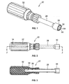
FIG. 1 is a perspective view of a driver for rotatably driving a threaded fastening member which incorporates the features of the present invention; -
FIG. 2 is a side elevational view of the driver; -
FIG. 3 is a cross-sectional view of the driver along line 3-3 ofFIG. 2 ; -
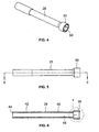
FIG. 4 is a perspective view of an elongated shank which forms part of the driver; -
FIG. 5 is a side elevational view of the elongated shank; -
FIG. 6 is a cross-sectional view of the elongated shank along line 5-5 ofFIG. 5 ; -
FIG. 7 is an enlarged partial cross-sectional view of the elongated shank; -
FIG. 8 is a perspective view of a conventional fastening member that is used with the driver; and -
FIG. 9 is a side elevational view of the nut ofFIG. 8 . - While the invention may be susceptible to embodiment in different forms, there is shown in the drawings, and herein will be described in detail, a specific embodiment with the understanding that the present disclosure is to be considered an exemplification of the principles of the invention, and is not intended to limit the invention to that as illustrated and described herein.
- A
driver 20 is provided for manually rotatably driving an associated rotatable threadedfastening member 22, such as a conventional hexagonal nut, which is shown inFIG. 8 . The fasteningmember 22 includes a plurality offaces 24 and an internally threadedbore 26 extending axially between opposedparallel end faces faces 24 are flat and do not taper from oneend face 25 to theother end face 27. Thefastening member 22 is adapted for threaded engagement with the shank of an associated screw or bolt (not shown). While a nut is illustrated in the drawings in connection with thedriver 20, it will be appreciated that thedriver 20 could also be used for driving a headed fastener. Achamfer 29 may be provided at the corner between thefaces 24 and the respective end faces 25, 27. - The
driver 20 includes anelongated shank 28 which has asocket 30 at a front end of theshank 28. As shown, theshank 28 andsocket 30 are integrally formed of metal. If desired, thesocket 30 can be formed separately from theshank 28 and fixedly secured thereto by suitable means. A rear end of theshank 28 is attached to ahandle 32. Thehandle 32 may be formed of metal and plastic or any other suitable materials. - The
handle 32 is known in the art and has an exterior surface with a plurality offlats 34 thereon which the user can use to grip thehandle 32. Ablind bore 36 is provided in a front end of thehandle 32 and extends rearwardly a predetermined amount. Theblind bore 36 terminates at awall 38. - The
shank 28 has an external surface defined by an outer wall which is preferably cylindrical in shape. Afirst portion 40 of theshank 28 extends from thesocket 30 to asecond portion 42 of theshank 28. Thesecond portion 42 has an exterior dimension which is larger than thefirst portion 40. In use, thesecond portion 42 is inserted into the blind bore 36 in thehandle 32 and attached thereto by known means. Therear face 44 of theshank 28 preferably abuts against thewall 38 within thehandle 32. - The
socket 30 has anouter wall 43 which has an outer dimension that is greater than the outer dimension of outer wall of theshank 28. Theouter wall 43 is preferably cylindrically shaped. Achamfer 45 may be provided at the corner between afront face 47 of thesocket 30 and theouter wall 43. Anangled wall 46 of thesocket 30 connects theouter wall 43 to the outer wall of theshank 28. - A
bore 48, which is defined by an internal wall, extends through theshank 28 and thesocket 30 such that thebore 48 extends from thefront face 47 to the rear end face of theshank 28. In thesocket 30, thebore 48 defines areceptacle 50 for thefastening member 22. Thereceptacle 50 includes afront portion 52 which extends from thefront face 47 of thesocket 30 rearwardly a predetermined distance, amiddle portion 54 which extends from the rear of the front portion 50 a rearwardly predetermined distance, atransition portion 56 which extends rearwardly from the rear of themiddle portion 54 to arear portion 58. - The
front portion 52 extends 360° within thereceptacle 50. Thefront portion 52 is dimensioned such that thefront portion 52 is larger than the outer dimension of the associatedfastening member 22. Thefront portion 52 can take a variety of shapes, such as a hexagon such that a plurality of flats are provided as the wall which forms thefront portion 52, the flats being parallel to acenterline 55 of thedriver 20, or a series of flutes and intersecting surfaces such as those disclosed in United States Patent No.3,495,485 which disclosure is herein incorporated by reference, the flutes and intersecting surfaces disclosed in United States Patent No.3,495,485 being parallel to thecenterline 55. With either of these shapes for thefront portion 52 and themiddle portion 54, thereceptacle 50 is compatible with a standard hexagonal nut. While, in the illustrated embodiment, thefront portion 52 are hexagonal in shape for accommodating a standard hexagonal nut, it will be appreciated that thefront portion 52 could be shaped to accommodate any other shape of the fastening member. - The tapered
middle portion 54 extends uninterrupted 360° within thereceptacle 50. The taperedmiddle portion 54 is spaced from thefront face 47 by thefront portion 52. Themiddle portion 54 continuously tapers inwardly toward thecenterline 55 of thedriver 20. The angle at which themiddle portion 54 tapers is slight, preferably 2.5 degrees relative to thecenterline 55. Themiddle portion 54 has a dimension which is largest at the end joined with thefront portion 52 and a dimension which is smallest at the end joined with thetransition portion 56. The smallest dimension of themiddle portion 54 is less than the outer dimension of the associatedfastening member 22 such that thefastening member 22 cannot pass through thereceptacle 50. Themiddle portion 54 is preferably formed as a hexagon such that a plurality of flats are provided as the wall which forms themiddle portion 54. - The
front portion 52 extends for only a short distance, for example 0.065 inches. The taperedportion 54 extends for a much greater distance, for example 0.39 inches. - The
transition portion 56 is frusto-conical in shape. Therear portion 58 is preferably cylindrical and is parallel to thecenterline 55. Therear portion 58 has a dimension which is smaller than the smallest dimension of thefront portion 52. Therear portion 58 transitions into the portion of thebore 48 which extends through theshank 28, and therear portion 58 and the portion of thebore 48 which extends through theshank 28 are preferably cylindrical in shape. - The tapered
middle portion 54 provides for locking thefastening member 22 in thesocket 30 by a taper lock. The "lock" is caused by friction between the taperedmiddle portion 54 and thefastening member 22. Because thereceptacle 50 has a slight taper and thefaces 24 of thefastening member 22 are not tapered, the frictional "lock" is only generated along points of line contact (i.e., a hexagon) between the taperedmiddle portion 54 and thefastening member 22. The amount of friction generated is sufficient to hold thefastening member 22 in place, while still allowing thefastening member 22 to be removed from thereceptacle 50 with minimal effort. Because the taperedmiddle portion 54 provides for locking thefastening member 22 in thereceptacle 50, the need for a magnet as provided in the prior art is eliminated. As a result, the cost of thedriver 20 is reduced since these additional components are not needed, and this simplifies manufacturing. Thedriver 20 can be formed by cold forging, and the taperedmiddle portion 54 can be easily added during the forging operation. In fact, providing the taperedmiddle portion 54 during the forging operation provides an advantage in that it is easier to strip thesocket 30 from the punch during forming. - During insertion of the
fastening member 22 into thesocket 30, thefastening member 22 does not contact the entire circumference of the front portion 52 (and may not contact any of thefront portion 52 depending on how the fasteningmember 22 is inserted and the exact geometry of the front portion 52) as thefastening member 22 is dimensionally smaller than thefront portion 52. Thefastening member 22 and thesocket 30 are engaged together at the points of line contact between the taperedmiddle portion 54 and thefaces 24 of thefastening member 22. Thefront portion 52 acts a spacer to situate the taperedmiddle portion 54 further back in thesocket 30, thereby allowing for theconventional fastening member 22 to be more fully inserted into thesocket 30 prior to engagement with the taperedmiddle portion 54 so that more (or all) of thefastening member 22 is seated within thesocket 30. In addition, this provides a distinct advantage over the nut driver of United States Patent No.6,045,311 if a user attempted to use a conventional nut therein. Since the walls which form the receptacle are tapered from the end face of the socket, if a conventional nut were to be inserted therein, the nut would be stopped from entering further into the receptacle as soon as the corners of the nut engage the tapered wall. For a nut that is larger, the nut may not be able to inserted to any appreciable extent into the receptacle of United States Patent No.6,045,311 . - In operation, the
fastening member 22 is inserted into thereceptacle 50 with thesocket 30 facing up and gravity causes thefastening member 22 to slide down into thesocket 30 and engage the taper of the taperedmiddle portion 54 to create the lock. Thefastening member 22 continuously contacts the taperedmiddle portion 54. The user then taps thehandle 32 down onto a solid surface with thesocket 30 still in the up position. This causes a dynamic force from the mass of thefastening member 22 times the acceleration/deceleration, thereby wedging thefastening member 22 into place, "locking" thefastening member 22 so that thefastening member 22 will not disengage from thedriver 20 regardless of thedriver 20 orientation. The user then grasps thehandle 32 and rotates thedriver 20 to rotate thefastening member 22. To remove thefastening member 22, the process is reversed by tapping thesocket 30 down onto a hard surface to remove thefastening member 22. - All drivers, such as hex socket wrenches, have a small amount of clearance built into the design to ensure that all fasteners of the correct nominal size will always fit. The clearance amount is dictated by ASME standards for both the socket and fastener sizes/tolerances. The clearance amount increases with the nominal fastener size, but is typically on the order of only a few thousandths of an inch. Therefore, a small amount of relative rotation between the
socket 30 and thefastening member 22 occurs during usage up to the point where the corners of thefastening member 22 contact thefront portion 52 along the lines of contact that are parallel to the rotational axis of thesocket 30 and thefastening member 22. - The dimensions of the
front portion 52 are dictated by the ASME standard. The depth of thefront portion 52 is sized such that afastening member 22 at the maximum allowable size and thickness will fit into thesocket 30 of minimum size without extending outwardly from the end of thesocket 30. The overall length of thefront portion 52 plus themiddle portion 54 is determined by the minimum size of thefastening member 22 that will be "held" by asocket 30 of maximum size. In other words, thefastening member 22 cannot fall to the bottom of thesocket 30 without contacting the taperedmiddle portion 54. -
Most fastening members 22 have achamfer 29 around the perimeter of both sides thereof, breaking the sharp edges that would otherwise be present. Unlike a standard socket, afastening member 22 inserted into thesocket 30 will start out with point and/or line contact around the perimeter of one side of thefastening member 22. With thechamfer 29 present, the contact is reduced to six points at the midpoint of each edge around the perimeter. Without achamfer 29, the contact will be along the six edges of the perimeter. - Friction is sufficient to transfer very low torques to the
fastening member 22 held in thesocket 30 as a result of the points of contact. However, as the torque increases, thefastening member 22 will start to rotate relative to thesocket 30. Applicant believes that the rotation happens either because the friction is insufficient to prevent sliding of the contact surfaces or else the contact points are being deformed providing greater contact area, which in turn transfers more torque. Either way, at some point, the relative rotation becomes great enough that the corners of thefastening member 22 contact the walls of thefront portion 52 and form lines of contact. This is similar to the way that torque is transferred in a normal socket with the exception that the length of the lines are shorter due to the shorter depth of thefront portion 52. Applicant has verified through testing that thesocket 30 is capable of exceeding the ASME proof torques by greater than 30% without damage to thefastening member 22. - While a preferred embodiment of the present invention is shown and described, it is envisioned that those skilled in the art may devise various modifications of the present invention without departing from the spirit and scope of the appended claims.
Claims (15)
- A driver for manually rotatably driving an associated fastening member having an outer dimension, said driver comprising:an elongated shank having a front end and a rear end, said shank defining a centerline;a handle provided at said rear end of said shank;a socket provided at said front end of said shank, said socket having a receptacle therein for receiving the associated fastening member, said receptacle including a front portion extending from a front face of the socket rearwardly a predetermined distance toward said shank and a tapered portion extending from a rear of said front portion a predetermined distance toward said shank, said front portion being dimensioned such that said front portion is larger than the outer dimension of the associated fastening member and is formed from a plurality of walls which are parallel to said centerline, and said tapered portion tapering inwardly from said front portion toward said centerline such that a largest dimension of said tapered portion is joined with said front portion and a smallest dimension of said tapered portion is spaced from said front portion, said smallest dimension of said tapered portion being less than the outer dimension of the associated fastening member, said tapered portion extending uninterrupted 360° around said receptacle such that a rear edge of the associated fastening member continuously contacts the tapered portion when inserted therein.
- A driver as defined in claim 1 in combination with a fastening member, said fastening member having a plurality of faces and an internally threaded bore extending axially between opposed parallel end faces, each of said plurality of faces being flat such that each of said plurality of faces does not taper from one end face to the other end face.
- A driver as defined in claim 1, wherein said tapered portion tapers at an angle of 2.5 degrees relative to said centerline.
- A driver as defined in claim 3 in combination with a fastening member, said fastening member having a plurality of faces and an internally threaded bore extending axially between opposed parallel end faces, each of said plurality of faces being flat such that each of said plurality of faces does not taper from one end face to the other end face.
- A driver as defined in claim 1 or claim 3, wherein said tapered portion is formed of a plurality of flats.
- A driver as defined in claim 3, wherein said front portion and said tapered portion are formed as hexagons such that a plurality of flats are provided on each of said front portion and said tapered portion.
- A driver as defined in claim 6 in combination with a fastening member, said fastening member having a plurality of faces and an internally threaded bore extending axially between opposed parallel end faces, each of plurality of faces being flat such that each of said plurality of faces does not taper from one end face to the other end face.
- A driver as defined in claim 5 in combination with a fastening member, said fastening member having a plurality of faces and an internally threaded bore extending axially between opposed parallel end faces, each of said plurality of faces being flat such that each of said faces does not taper from one end face to the other end face.
- A driver as defined in claim 1, wherein said receptacle further includes a frusto-conical portion extending from a rear of said tapered portion a predetermined distance, and a rear portion extending from a rear of said frusto-conical portion.
- A driver as defined in claim 1, wherein said shank and said socket are integrally formed of metal.
- A driver as defined in claim 1, wherein said shank and said socket are formed of metal.
- A driver as defined in claim 1, wherein said handle has an exterior surface with a plurality of flats thereon.
- A method comprising:providing a fastening member having an outer dimension;providing a driver including an elongated shank having a front end and a rear end, said shank defining a centerline, a handle provided at said rear end of said shank, a socket provided at said front end of said shank, said socket having a receptacle therein for receiving the associated fastening member, said receptacle including a front portion extending from a front face of the socket rearwardly a predetermined distance toward said shank and a tapered portion extending from a rear of said front portion a predetermined distance toward said shank, said front portion being dimensioned such that said front portion is larger than the outer dimension of the associated fastening member and is formed from a plurality of walls which are parallel to said centerline, and said tapered portion tapering inwardly from said front portion toward said centerline such that a largest dimension of said tapered portion is joined with said front portion and a smallest dimension of said tapered portion is spaced from said front portion, said tapered portion extending uninterrupted 360° around said receptacle;inserting the fastening member within said receptacle until a rear edge of the associated fastening member continuously contacts the tapered portion; andgrasping said handle to rotate said driver.
- A method as defined in claim 13, wherein during said step of inserting the fastening member within said receptacle, said socket is faced up and gravity causes the fastening member to slide down into the socket and engage the tapered portion.
- A method as defined in claim 14, wherein after said step of inserting the fastening member the handle is tapped onto a solid surface with the socket still facing up.
Applications Claiming Priority (1)
| Application Number | Priority Date | Filing Date | Title |
|---|---|---|---|
| US12100008P | 2008-12-09 | 2008-12-09 |
Publications (1)
| Publication Number | Publication Date |
|---|---|
| EP2196287A1 true EP2196287A1 (en) | 2010-06-16 |
Family
ID=41665497
Family Applications (1)
| Application Number | Title | Priority Date | Filing Date |
|---|---|---|---|
| EP09252755A Withdrawn EP2196287A1 (en) | 2008-12-09 | 2009-12-09 | Driver with tapered hex socket |
Country Status (2)
| Country | Link |
|---|---|
| US (1) | US8245603B2 (en) |
| EP (1) | EP2196287A1 (en) |
Cited By (2)
| Publication number | Priority date | Publication date | Assignee | Title |
|---|---|---|---|---|
| US8607670B2 (en) | 2011-02-18 | 2013-12-17 | Rafal Stawarski | Damaged fastener extractor |
| CN105252476A (en) * | 2015-11-16 | 2016-01-20 | 上海永乾机电有限公司 | Fast changing device for clamps |
Families Citing this family (10)
| Publication number | Priority date | Publication date | Assignee | Title |
|---|---|---|---|---|
| US20170036324A1 (en) * | 2009-05-01 | 2017-02-09 | James W. Taylor, Jr. | Socket insert adapter and method of use |
| DK2667017T3 (en) * | 2012-05-22 | 2015-03-09 | Siemens Ag | Set of a plurality of alignment tools in the field of wind turbines for tower and bottom alignment |
| USD718585S1 (en) * | 2013-03-12 | 2014-12-02 | Klein Tools, Inc. | Punch down tool |
| US20140263872A1 (en) * | 2013-03-15 | 2014-09-18 | Shaffarne, LLC | Apparatus For Use With Decorative Lighting |
| US20140360318A1 (en) * | 2013-06-10 | 2014-12-11 | Brian James Cutler | High speed lugnut socket |
| JP5920325B2 (en) * | 2013-11-11 | 2016-05-18 | 株式会社デンソー | Biasing force adjusting device, hydraulic control valve using the same, and method of manufacturing biasing force adjusting device |
| US11806843B2 (en) * | 2013-11-15 | 2023-11-07 | Snap-On Incorporated | Socket drive improvement |
| US11554470B2 (en) * | 2017-12-13 | 2023-01-17 | Apex Brands, Inc. | Extractor socket with bidirectional driving capability and corresponding extraction set with intermediate sizes |
| SE2130347A1 (en) * | 2021-12-08 | 2023-02-21 | Atlas Copco Ind Technique Ab | Socket for power tool, methods of controlling power tools, control systems and power tools |
| USD1081313S1 (en) | 2022-09-22 | 2025-07-01 | Apex Brands, Inc. | Extractor insert |
Citations (9)
| Publication number | Priority date | Publication date | Assignee | Title |
|---|---|---|---|---|
| US1590200A (en) * | 1924-05-02 | 1926-06-29 | John J Mcguckin | Socket wrench |
| US3495485A (en) | 1966-09-14 | 1970-02-17 | Snap On Tools Corp | Wrench sockets,socket drives and similar couplers |
| US4126063A (en) * | 1975-11-14 | 1978-11-21 | Palmer Richard R | Wrench sockets |
| US4503737A (en) * | 1983-04-11 | 1985-03-12 | Digiovanni Donald | Threaded fastener removing tool |
| US5163345A (en) | 1992-02-25 | 1992-11-17 | Snap-On Tools Corporation | Spring-loaded magnetic driver and method of assembly thereof |
| US6003411A (en) * | 1998-02-02 | 1999-12-21 | Snap-On Tools Company | Cam-lobed salvage tool |
| US6045311A (en) | 1998-09-10 | 2000-04-04 | Chang; Peter Jenn-Hai | Bolt, nut, and wrench in taper design for turning the bolt and the nut |
| EP1025959A2 (en) * | 1999-02-08 | 2000-08-09 | Black & Decker Inc. | Nutsetter |
| US7437975B1 (en) * | 2002-05-13 | 2008-10-21 | Michael De Anfrasio | Wrench socket |
Family Cites Families (10)
| Publication number | Priority date | Publication date | Assignee | Title |
|---|---|---|---|---|
| US1321776A (en) * | 1919-11-11 | Wbeztch | ||
| US5361657A (en) * | 1991-08-15 | 1994-11-08 | Terry Elliott P | Drive socket |
| US5277531A (en) * | 1992-09-10 | 1994-01-11 | Snap-On Tools Corporation | Device having socket with retention surfaces |
| US5544555A (en) * | 1995-05-23 | 1996-08-13 | Corley; Ronald E. | Wrench socket |
| US5682801A (en) * | 1996-03-26 | 1997-11-04 | Waechter; Thomas R. | Jam proof lug nut |
| US6626067B1 (en) * | 2000-09-27 | 2003-09-30 | Snap-On Technologies, Inc. | Retention socket geometry variations |
| US6840139B2 (en) * | 2003-05-08 | 2005-01-11 | Alcoa Global Fasteners, Inc. | Tapered installation tool |
| US20050139042A1 (en) * | 2003-12-31 | 2005-06-30 | Lisa Leighton | Universal gas valve key |
| US20060236822A1 (en) * | 2005-04-26 | 2006-10-26 | Nish Jeffery L | Threaded member driver with retention system |
| US7661338B2 (en) * | 2007-05-01 | 2010-02-16 | Kochling Edmund T | Socket assembly for a gate valve wrench |
-
2009
- 2009-12-08 US US12/633,224 patent/US8245603B2/en active Active
- 2009-12-09 EP EP09252755A patent/EP2196287A1/en not_active Withdrawn
Patent Citations (9)
| Publication number | Priority date | Publication date | Assignee | Title |
|---|---|---|---|---|
| US1590200A (en) * | 1924-05-02 | 1926-06-29 | John J Mcguckin | Socket wrench |
| US3495485A (en) | 1966-09-14 | 1970-02-17 | Snap On Tools Corp | Wrench sockets,socket drives and similar couplers |
| US4126063A (en) * | 1975-11-14 | 1978-11-21 | Palmer Richard R | Wrench sockets |
| US4503737A (en) * | 1983-04-11 | 1985-03-12 | Digiovanni Donald | Threaded fastener removing tool |
| US5163345A (en) | 1992-02-25 | 1992-11-17 | Snap-On Tools Corporation | Spring-loaded magnetic driver and method of assembly thereof |
| US6003411A (en) * | 1998-02-02 | 1999-12-21 | Snap-On Tools Company | Cam-lobed salvage tool |
| US6045311A (en) | 1998-09-10 | 2000-04-04 | Chang; Peter Jenn-Hai | Bolt, nut, and wrench in taper design for turning the bolt and the nut |
| EP1025959A2 (en) * | 1999-02-08 | 2000-08-09 | Black & Decker Inc. | Nutsetter |
| US7437975B1 (en) * | 2002-05-13 | 2008-10-21 | Michael De Anfrasio | Wrench socket |
Cited By (2)
| Publication number | Priority date | Publication date | Assignee | Title |
|---|---|---|---|---|
| US8607670B2 (en) | 2011-02-18 | 2013-12-17 | Rafal Stawarski | Damaged fastener extractor |
| CN105252476A (en) * | 2015-11-16 | 2016-01-20 | 上海永乾机电有限公司 | Fast changing device for clamps |
Also Published As
| Publication number | Publication date |
|---|---|
| US8245603B2 (en) | 2012-08-21 |
| US20100154602A1 (en) | 2010-06-24 |
Similar Documents
| Publication | Publication Date | Title |
|---|---|---|
| US8245603B2 (en) | Driver with tapered hex socket | |
| US6868757B2 (en) | Blind fastener and nose assembly for installation of the blind fastener | |
| US7066062B2 (en) | Torque-setting, tamper-resistant fastener and method and tool for use with same | |
| JP7485257B2 (en) | Tapered lobe drivers and fasteners | |
| EP0570040A1 (en) | Back-side taper wedging drive system | |
| US10759027B2 (en) | Socket and bit retention | |
| US20080066580A1 (en) | Retention socket | |
| EP1248001A2 (en) | Blind fastener and drive nut assembly and method for assembling such blind fastener | |
| KR20100049603A (en) | Blind fastener and nose assembly for installation thereof | |
| US20090087280A1 (en) | Reuseable lock nut device | |
| US6152000A (en) | Driver bit and driver | |
| US20030075027A1 (en) | Driving heads for fasteners | |
| US20100269643A1 (en) | Nut capturing socket assembly | |
| US6935214B2 (en) | Noback bolt | |
| JPS58502162A (en) | socket drive | |
| AU684600B2 (en) | Insert nut and fastener | |
| EP1031740A1 (en) | Improved structure of a multi-angle nut and its driving or unscrewing tool | |
| EP0926362A1 (en) | Fastener having multiple-drive head and method of manufacture thereof | |
| EP1691087A3 (en) | Frangible Blind Rivet | |
| US20050204875A1 (en) | Anti-tamper fastener | |
| EP0158304A1 (en) | Fastener | |
| EP1477689A2 (en) | One way threaded security fastener and installation tool | |
| JP2004526584A (en) | Tool edge | |
| AU2014200312B2 (en) | Fastener Driver | |
| CA3096204A1 (en) | Ratchet wrench |
Legal Events
| Date | Code | Title | Description |
|---|---|---|---|
| PUAI | Public reference made under article 153(3) epc to a published international application that has entered the european phase |
Free format text: ORIGINAL CODE: 0009012 |
|
| AK | Designated contracting states |
Kind code of ref document: A1 Designated state(s): AT BE BG CH CY CZ DE DK EE ES FI FR GB GR HR HU IE IS IT LI LT LU LV MC MK MT NL NO PL PT RO SE SI SK SM TR |
|
| AX | Request for extension of the european patent |
Extension state: AL BA RS |
|
| 17P | Request for examination filed |
Effective date: 20101215 |
|
| 17Q | First examination report despatched |
Effective date: 20131022 |
|
| STAA | Information on the status of an ep patent application or granted ep patent |
Free format text: STATUS: THE APPLICATION IS DEEMED TO BE WITHDRAWN |
|
| 18D | Application deemed to be withdrawn |
Effective date: 20170118 |