EP2196157A1 - Suture packaging - Google Patents
Suture packaging Download PDFInfo
- Publication number
- EP2196157A1 EP2196157A1 EP09252752A EP09252752A EP2196157A1 EP 2196157 A1 EP2196157 A1 EP 2196157A1 EP 09252752 A EP09252752 A EP 09252752A EP 09252752 A EP09252752 A EP 09252752A EP 2196157 A1 EP2196157 A1 EP 2196157A1
- Authority
- EP
- European Patent Office
- Prior art keywords
- suture
- package
- raised portions
- retaining area
- base member
- Prior art date
- Legal status (The legal status is an assumption and is not a legal conclusion. Google has not performed a legal analysis and makes no representation as to the accuracy of the status listed.)
- Granted
Links
Images





Classifications
-
- A—HUMAN NECESSITIES
- A61—MEDICAL OR VETERINARY SCIENCE; HYGIENE
- A61B—DIAGNOSIS; SURGERY; IDENTIFICATION
- A61B17/00—Surgical instruments, devices or methods
- A61B17/04—Surgical instruments, devices or methods for suturing wounds; Holders or packages for needles or suture materials
- A61B17/06—Needles ; Sutures; Needle-suture combinations; Holders or packages for needles or suture materials
- A61B17/06114—Packages or dispensers for needles or sutures
- A61B17/06133—Packages or dispensers for needles or sutures of parallelepipedal shape, e.g. made of rectangular or slightly oval panels
-
- A—HUMAN NECESSITIES
- A61—MEDICAL OR VETERINARY SCIENCE; HYGIENE
- A61B—DIAGNOSIS; SURGERY; IDENTIFICATION
- A61B17/00—Surgical instruments, devices or methods
- A61B17/04—Surgical instruments, devices or methods for suturing wounds; Holders or packages for needles or suture materials
- A61B17/06—Needles ; Sutures; Needle-suture combinations; Holders or packages for needles or suture materials
- A61B17/06114—Packages or dispensers for needles or sutures
- A61B2017/06142—Packages or dispensers for needles or sutures having needle- or suture- retaining members, e.g. holding tabs or needle parks
-
- A—HUMAN NECESSITIES
- A61—MEDICAL OR VETERINARY SCIENCE; HYGIENE
- A61B—DIAGNOSIS; SURGERY; IDENTIFICATION
- A61B17/00—Surgical instruments, devices or methods
- A61B17/04—Surgical instruments, devices or methods for suturing wounds; Holders or packages for needles or suture materials
- A61B17/06—Needles ; Sutures; Needle-suture combinations; Holders or packages for needles or suture materials
- A61B17/06114—Packages or dispensers for needles or sutures
- A61B2017/06157—Packages or dispensers for needles or sutures containing a suture wound in a sinusoidal or zigzag configuration
Definitions
- the present disclosure relates to packaging for sutures. More particularly, the present disclosure relates to suture packages for receiving barbed sutures.
- Sutures and packages for retaining sutures are known in the art.
- Suture packages may be of the foldable type, constructed from paper and configured to form a pocket for receiving one or more sutures therein.
- the suture packages may be of the molded variety. Such packages typically define a channel for the receipt of one or more sutures therein.
- Packaging for barbed sutures is not as well known in the art.
- Packaging barbed sutures is complicated by the configuration of the sutures.
- the barbs formed along the length of a barbed suture increase the likelihood that the suture may become entangled with itself or other barbed sutures.
- damage may result to the barbs formed on the suture, thereby diminishing the effectiveness of the suture.
- suture package configured to retain one or more barbed sutures such that the suture does not become entangled. It would be further beneficial if the suture package is configured to prevent the barbs from becoming flat or otherwise damaged.
- a suture package configured to retain one or more barbed suture.
- the suture package includes, a base member having an outer wall and a suture retaining area, at least one needle retainer positioned adjacent the suture retaining area for receiving at least one suture needle, at least one suture retainer positioned adjacent the suture retaining area for receiving a distal end of at least one suture, a plurality of raised portions formed within the suture retaining area, wherein each of the raised portions includes a groove for receiving a portion of at least one suture therein.
- the groove in each of the raised portions may be formed on an outer wall-facing surface of the raised portion.
- the groove in each of the raised portions may extend at least partially around the raised portion.
- the at least one needle retainer may include a foam strip.
- the at least one suture retainer may include a foam strip.
- the foam strip may be configured to receive a suture end effector.
- the raised portions may be disposed at an angle relative to the outer wall of the base member.
- the suture may be a barbed suture.
- the suture package may include at least five raised portions.
- the outer wall of the suture package may include a plurality of inward facing tabs for releasably engaging a cover.
- the suture package includes a base member having an outer wall and including a suture retaining area, a needle retainer positioned adjacent the suture retaining area for receiving a plurality of suture needles, a plurality of suture retaining means positioned adjacent the suture retaining area, each of the suture retaining means configured for receiving a distal end of a suture, and two or more pairs of longitudinally spaced and laterally offset raised portions formed within the suture retaining area configured to receive a suture thereabout, wherein each of the raised portions include a groove for selectively engaging a suture.
- the groove in each of the raised positions may be formed in a longitudinally outward facing surface of the raised portion.
- the groove in each of the raised portions may extend at least partially about the raised portion.
- the at least one needle retainer may include a foam strip.
- the at least one suture retainer may include a foam strip.
- the outer wall may include a plurality of inward facing tabs for releasably engaging one or more cover members.
- FIG. 1 is a perspective view of a suture package according to an embodiment of the present disclosure, including a base member and a cover member;
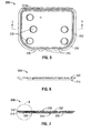
- FIG. 2 is a top view of the base member of the suture package of FIG. 1 ;
- FIG. 3 is a side view of the base member of FIG. 2 ;
- FIG. 4 is a top view of the base member of FIGS. 2 and 3 , including a barbed suture;
- FIG. 5 is a top view of a suture package according to an alternate embodiment of the present disclosure.
- FIG. 6 is a side view of the suture package of FIG. 5 ;
- FIG. 7 is a cross-section side view of the suture package of FIGS. 5 and 6 ;
- FIG. 8 is an enlarged cross-sectional view of a portion of the suture package of FIGS. 5-7 ;
- FIG. 9 is a perspective of a suture package according to another embodiment of the present disclosure, including a base member and a pair of cover members;
- FIG. 10 is a side view of the suture package of FIG. 9 ;
- FIG. 11 is a top view of the suture package of FIGS. 9 and 10 ;
- FIG. 12 is a top view of base member of the suture package of FIGS. 9-11 , including a plurality of barbed sutures;
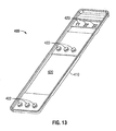
- FIG. 13 is a perspective view of a suture package according to yet another embodiment of the present disclosure.
- FIG. 14 is a top view of the suture package of FIG. 13 ;
- FIG. 15 is a side view of the suture package of FIG. 14 ;
- FIG. 16 is an end view of the suture package of FIG. 15 .
- a suture package having an end effector 20 on a first end, a needle 15 on an opposite end, and barbs 12 formed along the length thereof, it is envisioned that the aspects of the present disclosure may be modified for use with sutures of all sizes and configurations, including several types of needles and end effectors.
- the disclosure should not be limited to the sutures herein described.
- suture package 100 includes a base member 110 configured for receiving one or more sutures 10 ( FIG. 4 ) and a cover member 150 for retaining one or more sutures 10 within base member 110.
- base member 110 includes a substantially rectangular configuration, however, however, alternative configurations have been contemplated, including square, circular and elliptical.
- cover member 150 includes a substantially similar configuration as base member 110 and is configured to selectively engage base member 110.
- base member 110 of suture package 100 is configured to receive barbed suture 10 ( FIG. 4 ).
- Base member 110 may be formed of plastic, polymer or any other moldable material.
- Base 110 includes an outer wall 112 defining a suture retaining area 120.
- Suture retaining area 120 includes a plurality of raised portions 122 formed therein. Raised portions 122 may be integrally formed with base member 110, as shown. In an alternative embodiment, raised portions 122 may be securely affixed within suture retaining portion 120. Although shown as including five (5) raised portions 122, suture retaining portion 120 may include any number of raised portions 122. Raised portions 122 may be of any size or configuration.
- Raised portions 122 may be arranged in any configuration in which barbed suture 10 may be wrapped thereabout without barbs 12 of barbed suture 10 engaging one another.
- Raised portions 122 include grooves or slot 124 formed in an outwardly facing surface of raised portions 122. Grooves 124 are configured to receive a portion of barbed suture 10 therein. Although, as shown, grooves 124 only extend about an outwardly facing surface of raised portions 122, it is envisioned that grooves 124 may partially or completely circumscribe raised portions 122. It is further envisioned that each of raised portions 122 may include more than one groove 124 for receiving more than one barbed suture 10.
- grooves 124 may also be configured to support or suspend barbed suture 10 within suture retaining area 120 such that barbs 12 on barbed suture 10 minimally contact base member 110 and cover member 150.
- Raised portions 122 are of a sufficient height to support cover member 150 such that a space is created within suture retaining area 120 in which barbed suture 10 may be retained without barbs 12 formed thereon being compressed.
- suture retaining area 120 of base member 110 further includes at least one of a needle park 120a and a first foam pad 120b (both shown in phantom), for selectively receiving suture needle 15.
- Suture retaining area 120 may also include a second foam pad 120c (also shown in phantom) or other suture retaining means, for selectively retaining a distal end of barbed suture 10.
- second foam pad 120c is configured to selectively engage an end of suture 10 including end effector 20.
- suture needle 15 and/or end effector 20 of suture 10 may be loosely received with suture retaining area 120 of base member 110.
- Suture retaining area 120 further includes an aperture or slot 128 configured to selectively receive an alignment pin (not shown) of a loading apparatus (also not shown) for when a loading apparatus is used to load barbed suture 10 within suture retaining area 120.
- outer wall 112 of base member 110 includes a plurality of inwardly extending ridges 114 configured to releasably engage cover member 150. Ridges 114 are configured and positioned such that an outer perimeter of cover member 150 engages ridges 114 when cover member 150 is received within outer wall 112.
- Outer wall 112 of base member 110 further includes a tab region 116 extending outwardly from base member 110.
- Tab region 116 includes a bump 116a or otherwise raised configuration for permitting engagement of a tab portion 152 of cover member 150 by a clinician. Bump 116a maintains tab portion 152 spaced away from tab region 116, when cover member 150 is selectively engaged with base member 110.
- cover member 150 defines a substantially similar shape to base member 110.
- Cover member 150 may be formed of plastic, paper or any other semi-rigid material.
- Cover member 150 is configured to be received within suture retaining area 120 of base member 110 and selectively engage ridges 114 extending inwardly from outer wall 112.
- cover member 150 includes a tab portion 152 corresponding to tab region 116 formed in outer wall 112 of base member 110.
- Tab portion 152 of cover member 150 is configured for operable engagement by a clinician to permit separation of cover member 150 from base member 110 to expose barbed suture 10 retained within suture retaining area 120.
- Barbed suture 10 may be loaded into base member 110 manually or with the use of a loading apparatus.
- suture retaining area 120 of base member 110 includes an aperture 128 configured for receiving an alignment pin (not show) of a loading apparatus (also not shown).
- base member 110 is initially loaded onto the loading apparatus by aligning aperture 128 with an alignment pin of the loading apparatus.
- a first end of barbed suture 10 is loaded within one of needle park 120a, first foam pad 120b or second foam pad 120c, depending on whether the first end of barbed suture 10 includes end effector 20 or suture needle 15.
- Barbed suture 10 is then wrapped around each of raised portions 122 such that barbed suture 10 is received within grooves 124 formed therein. Once barbed suture 10 has been received about raised portions 122, the second end of barbed suture 10 is selectively received within the other of needle park 120a, first foam pad 120b and second foam pad 120c.
- cover member 150 is positioned within suture retaining area 120 such that tab region 116 of base member 110 and tab portion 152 of cover member 150 align. Cover member 150 is then selectively secured to base member 110 by engaging a perimeter of cover member 150 with ridges 114 extending inwardly from outer wall 112. Bump 116a formed on tab region 116 of base member 110 maintains tab portion 152 spaced from outer wall 112 to facilitate engagement by a clinician when access to suture 10 is necessary. Barbed suture 10 may be removed from suture package 100 in a reverse manner to its loaded. Suture package 100 may be hermetically sealed or otherwise packaged for shipping and handling.
- Suture package 200 is substantially similar to suture package 100.
- Suture package 200 includes a base member 210 and a cover member 250.
- Base member 210 includes an outer wall 212 defining a suture retaining area 220.
- Suture retaining area 220 includes a plurality of raised portions 222 configured to selectively retain barbed suture 10 ( FIG. 4 ).
- Cover member 250 is composed of a rigid plastic and may be clear to permit viewing of the contents thereunder. Cover member 250 is hingedly attached to a first length 212a of outer wall 212.
- Cover member 250 is configured to be folded along first length 212a and over suture retaining area 220 to selectively retain barbed suture 10 within suture retaining area 220. In one embodiment, cover member 250 contacts raised portions 222 to prevent barbed sutures 10 from disengaging raised portions 222, however, in alternate embodiments cover member 250 may not contact raised portions 222.
- An outer perimeter 252 of cover member 250 is configured to selectively engage outer wall 212. In one embodiment, outer perimeter 252 engages outer wall 212 in a snap-fit manner ( FIG. 5 ). Outer perimeter 252 may extend completely about cover member 250, as shown, or outer perimeter 252 may extend about only a portion of cover member 250. Barbed suture 10 is loaded and unloaded from suture package 200 in substantially the same manner as barbed suture 10 is loaded and unloaded from suture package 100.
- Suture package 300 is substantially similar to suture packages 100, 200 described hereinabove.
- Suture package 300 includes an elongated base member 310 configured to receive a plurality of sutures 10a-c ( FIG. 12 ).
- the length of base member 310 determines the length of sutures 10a-c.
- Sutures 10a-c may be of any size or configuration and may be identical to one another or different.
- Base member 310 includes an outer wall 312 that defines a suture retaining area 320.
- a plurality of raised portions 322 are formed in suture retaining area 320 and are configured to selectively engage a plurality of barbed sutures 10 thereabout.
- Each pair of raised portions 322 are longitudinally spaced and laterally offset from one another such that suture 10a may be wrapped thereabout without the barbs 12a of the suture engaging one another or the barbs 12b of an adjacent suture 10b.
- base member 310 includes three (3) pairs of raised portions 322 configured to receive three (3) barbed sutures 10a-c
- base member 310 may be configured to with any number (n) of pairs of raised portions 322 to receive any number (n) of barbed sutures 10.
- a needle retaining foam strip 320a is configured to receive needles 15a-c of sutures 10a-c.
- a plurality of foam pads 320c are configured to engage a end of respective suture 10a-c including end effector 20a-c.
- a plurality of ridges 314 extend inwardly from outer wall 312 in a manner similar to ridges 114 described on outer wall 112 of base member 110 of suture package 100 hereinabove. Ridges 314 are configured to selectively engage cover members 350a, 350b.
- cover members 350a, 350b may be formed of plastic, paper or any other semi-rigid material.
- Cover members 350a, 350b are configured to be received within suture retaining area 320 of base member 310 and selectively engage ridges 314 extending inwardly from outer wall 312.
- Cover members 350a, 350b selectively retain suture 10a-c within suture retaining area 320. Once sutures 10a-c are securely received within suture retaining area 320, suture package 300 may be hermetically sealed in any known manner.
- Suture package 400 is substantially identical to suture package 300 described hereinabove.
- Suture package 400 includes an elongated base member 410 configured to selectively retain a plurality of sutures ( FIG. 12 ).
- Base member 410 includes an outer wall 412 that defines a suture retaining area 420.
- Suture retaining area 420 includes a plurality of pairs of raised portions 422.
- Suture retaining area 420 further includes reference characters 423 formed thereon in alignment with raised portions 422 that maybe used a clinician to identify the type of suture retained on each of the pairs of raised portions 222.
- Suture package 400 is loaded in substantially the same manner as each of suture packages 100, 200, 300 described hereinabove.
Landscapes
- Health & Medical Sciences (AREA)
- Surgery (AREA)
- Life Sciences & Earth Sciences (AREA)
- Biomedical Technology (AREA)
- Nuclear Medicine, Radiotherapy & Molecular Imaging (AREA)
- Engineering & Computer Science (AREA)
- Dentistry (AREA)
- Heart & Thoracic Surgery (AREA)
- Medical Informatics (AREA)
- Molecular Biology (AREA)
- Animal Behavior & Ethology (AREA)
- General Health & Medical Sciences (AREA)
- Public Health (AREA)
- Veterinary Medicine (AREA)
- Surgical Instruments (AREA)
Abstract
Description
- The present disclosure relates to packaging for sutures. More particularly, the present disclosure relates to suture packages for receiving barbed sutures.
- Sutures and packages for retaining sutures are known in the art. Suture packages may be of the foldable type, constructed from paper and configured to form a pocket for receiving one or more sutures therein. Alternatively, the suture packages may be of the molded variety. Such packages typically define a channel for the receipt of one or more sutures therein.
- Packaging for barbed sutures is not as well known in the art. Packaging barbed sutures is complicated by the configuration of the sutures. In addition to the normal problems associated with packaging multiple sutures or overlapping lengths of the same suture, namely, entangling of the suture(s), the barbs formed along the length of a barbed suture increase the likelihood that the suture may become entangled with itself or other barbed sutures. When excessive force is applied to the barbs while untangling the suture, damage may result to the barbs formed on the suture, thereby diminishing the effectiveness of the suture.
- Therefore, it would be beneficial to have a suture package configured to retain one or more barbed sutures such that the suture does not become entangled. It would be further beneficial if the suture package is configured to prevent the barbs from becoming flat or otherwise damaged.
- Accordingly, a suture package configured to retain one or more barbed suture is provided. The suture package includes, a base member having an outer wall and a suture retaining area, at least one needle retainer positioned adjacent the suture retaining area for receiving at least one suture needle, at least one suture retainer positioned adjacent the suture retaining area for receiving a distal end of at least one suture, a plurality of raised portions formed within the suture retaining area, wherein each of the raised portions includes a groove for receiving a portion of at least one suture therein.
- The groove in each of the raised portions may be formed on an outer wall-facing surface of the raised portion. The groove in each of the raised portions may extend at least partially around the raised portion. The at least one needle retainer may include a foam strip. The at least one suture retainer may include a foam strip. The foam strip may be configured to receive a suture end effector. The raised portions may be disposed at an angle relative to the outer wall of the base member. The suture may be a barbed suture. The suture package may include at least five raised portions. The outer wall of the suture package may include a plurality of inward facing tabs for releasably engaging a cover.
- An alternate embodiment of a suture package configured to retain one or more barbed sutures is also provided. The suture package includes a base member having an outer wall and including a suture retaining area, a needle retainer positioned adjacent the suture retaining area for receiving a plurality of suture needles, a plurality of suture retaining means positioned adjacent the suture retaining area, each of the suture retaining means configured for receiving a distal end of a suture, and two or more pairs of longitudinally spaced and laterally offset raised portions formed within the suture retaining area configured to receive a suture thereabout, wherein each of the raised portions include a groove for selectively engaging a suture.
- The groove in each of the raised positions may be formed in a longitudinally outward facing surface of the raised portion. The groove in each of the raised portions may extend at least partially about the raised portion. The at least one needle retainer may include a foam strip. The at least one suture retainer may include a foam strip. The outer wall may include a plurality of inward facing tabs for releasably engaging one or more cover members.
- The accompanying drawings, which are incorporated in and constitute a part of this specification, illustrate embodiments of the disclosure and, together with a general description of the disclosure given above, and the detailed description of the embodiments given below, serve to explain the principles of the disclosure, wherein:
-
FIG. 1 is a perspective view of a suture package according to an embodiment of the present disclosure, including a base member and a cover member; -
FIG. 2 is a top view of the base member of the suture package ofFIG. 1 ; -
FIG. 3 is a side view of the base member ofFIG. 2 ; -
FIG. 4 is a top view of the base member ofFIGS. 2 and 3 , including a barbed suture; -
FIG. 5 is a top view of a suture package according to an alternate embodiment of the present disclosure; -
FIG. 6 is a side view of the suture package ofFIG. 5 ; -
FIG. 7 is a cross-section side view of the suture package ofFIGS. 5 and 6 ; -
FIG. 8 is an enlarged cross-sectional view of a portion of the suture package ofFIGS. 5-7 ; -
FIG. 9 is a perspective of a suture package according to another embodiment of the present disclosure, including a base member and a pair of cover members; -
FIG. 10 is a side view of the suture package ofFIG. 9 ; -
FIG. 11 is a top view of the suture package ofFIGS. 9 and10 ; -
FIG. 12 is a top view of base member of the suture package ofFIGS. 9-11 , including a plurality of barbed sutures; -
FIG. 13 is a perspective view of a suture package according to yet another embodiment of the present disclosure; -
FIG. 14 is a top view of the suture package ofFIG. 13 ; -
FIG. 15 is a side view of the suture package ofFIG. 14 ; and -
FIG. 16 is an end view of the suture package ofFIG. 15 . - The following disclosure will describe various embodiments of a suture package. Although continued reference will be made to a barbed suture 10 (
FIG. 2 ), having anend effector 20 on a first end, aneedle 15 on an opposite end, andbarbs 12 formed along the length thereof, it is envisioned that the aspects of the present disclosure may be modified for use with sutures of all sizes and configurations, including several types of needles and end effectors. The disclosure should not be limited to the sutures herein described. - With reference to
FIGS. 1-4 , a first embodiment of a suture package according to the present disclosure is shown generally assuture package 100. Refening initially toFIG. 1 ,suture package 100 includes abase member 110 configured for receiving one or more sutures 10 (FIG. 4 ) and acover member 150 for retaining one ormore sutures 10 withinbase member 110. As shown,base member 110 includes a substantially rectangular configuration, however, however, alternative configurations have been contemplated, including square, circular and elliptical. As will be discussed in further detail below,cover member 150 includes a substantially similar configuration asbase member 110 and is configured to selectively engagebase member 110. - Referring now to
FIGS. 2-4 ,base member 110 ofsuture package 100 is configured to receive barbed suture 10 (FIG. 4 ).Base member 110 may be formed of plastic, polymer or any other moldable material.Base 110 includes anouter wall 112 defining asuture retaining area 120. Sutureretaining area 120 includes a plurality of raisedportions 122 formed therein. Raisedportions 122 may be integrally formed withbase member 110, as shown. In an alternative embodiment, raisedportions 122 may be securely affixed withinsuture retaining portion 120. Although shown as including five (5) raisedportions 122,suture retaining portion 120 may include any number of raisedportions 122. Raisedportions 122 may be of any size or configuration. A wider raisedportion 122 requires less flexion ofbarbed suture 10 asbarbed suture 10 is wrapped about raisedportion 122. Raisedportions 122 may be arranged in any configuration in whichbarbed suture 10 may be wrapped thereabout withoutbarbs 12 ofbarbed suture 10 engaging one another. Raisedportions 122 include grooves or slot 124 formed in an outwardly facing surface of raisedportions 122.Grooves 124 are configured to receive a portion ofbarbed suture 10 therein. Although, as shown,grooves 124 only extend about an outwardly facing surface of raisedportions 122, it is envisioned thatgrooves 124 may partially or completely circumscribe raisedportions 122. It is further envisioned that each of raisedportions 122 may include more than onegroove 124 for receiving more than onebarbed suture 10. In this manner, multiplebarbed sutures 10 may be received and maintained separate from one another withinsuture retaining area 120.Grooves 124 may also be configured to support or suspendbarbed suture 10 withinsuture retaining area 120 such thatbarbs 12 onbarbed suture 10 minimallycontact base member 110 andcover member 150. Raisedportions 122 are of a sufficient height to supportcover member 150 such that a space is created withinsuture retaining area 120 in whichbarbed suture 10 may be retained withoutbarbs 12 formed thereon being compressed. - With particular reference to
FIG. 4 ,suture retaining area 120 ofbase member 110 further includes at least one of aneedle park 120a and afirst foam pad 120b (both shown in phantom), for selectively receivingsuture needle 15. Suture retainingarea 120 may also include asecond foam pad 120c (also shown in phantom) or other suture retaining means, for selectively retaining a distal end ofbarbed suture 10. As shown,second foam pad 120c is configured to selectively engage an end ofsuture 10 includingend effector 20. In an alternate embodiment,suture needle 15 and/orend effector 20 ofsuture 10 may be loosely received withsuture retaining area 120 ofbase member 110. Suture retainingarea 120 further includes an aperture or slot 128 configured to selectively receive an alignment pin (not shown) of a loading apparatus (also not shown) for when a loading apparatus is used to loadbarbed suture 10 withinsuture retaining area 120. - Turning back to
FIGS. 1-3 ,outer wall 112 ofbase member 110 includes a plurality of inwardly extendingridges 114 configured to releasably engagecover member 150.Ridges 114 are configured and positioned such that an outer perimeter ofcover member 150 engagesridges 114 whencover member 150 is received withinouter wall 112.Outer wall 112 ofbase member 110 further includes atab region 116 extending outwardly frombase member 110.Tab region 116 includes abump 116a or otherwise raised configuration for permitting engagement of atab portion 152 ofcover member 150 by a clinician.Bump 116a maintainstab portion 152 spaced away fromtab region 116, whencover member 150 is selectively engaged withbase member 110. - With reference still to
FIG. 1 ,cover member 150 defines a substantially similar shape tobase member 110.Cover member 150 may be formed of plastic, paper or any other semi-rigid material.Cover member 150 is configured to be received withinsuture retaining area 120 ofbase member 110 and selectively engageridges 114 extending inwardly fromouter wall 112. As discussed above,cover member 150 includes atab portion 152 corresponding totab region 116 formed inouter wall 112 ofbase member 110.Tab portion 152 ofcover member 150 is configured for operable engagement by a clinician to permit separation ofcover member 150 frombase member 110 to exposebarbed suture 10 retained withinsuture retaining area 120. - The use of
suture package 100 will now be described with reference toFIGS. 1-4 .Barbed suture 10 may be loaded intobase member 110 manually or with the use of a loading apparatus. As discussed above,suture retaining area 120 ofbase member 110 includes anaperture 128 configured for receiving an alignment pin (not show) of a loading apparatus (also not shown). In the event that a loading apparatus is used to loadbarbed suture 10 withinsuture package 100,base member 110 is initially loaded onto the loading apparatus by aligningaperture 128 with an alignment pin of the loading apparatus. Next, a first end ofbarbed suture 10 is loaded within one ofneedle park 120a,first foam pad 120b orsecond foam pad 120c, depending on whether the first end ofbarbed suture 10 includesend effector 20 orsuture needle 15.Barbed suture 10 is then wrapped around each of raisedportions 122 such thatbarbed suture 10 is received withingrooves 124 formed therein. Oncebarbed suture 10 has been received about raisedportions 122, the second end ofbarbed suture 10 is selectively received within the other ofneedle park 120a,first foam pad 120b andsecond foam pad 120c. - Once
barbed suture 10 is securely received withinsuture retaining area 120,cover member 150 is positioned withinsuture retaining area 120 such thattab region 116 ofbase member 110 andtab portion 152 ofcover member 150 align.Cover member 150 is then selectively secured tobase member 110 by engaging a perimeter ofcover member 150 withridges 114 extending inwardly fromouter wall 112.Bump 116a formed ontab region 116 ofbase member 110 maintainstab portion 152 spaced fromouter wall 112 to facilitate engagement by a clinician when access tosuture 10 is necessary.Barbed suture 10 may be removed fromsuture package 100 in a reverse manner to its loaded.Suture package 100 may be hermetically sealed or otherwise packaged for shipping and handling. - Turning now to
FIGS. 5-8 , an alternate embodiment of a suture package according to the present disclosure is shown generally assuture package 200.Suture package 200 is substantially similar tosuture package 100.Suture package 200 includes abase member 210 and acover member 250.Base member 210 includes anouter wall 212 defining asuture retaining area 220. Suture retainingarea 220 includes a plurality of raisedportions 222 configured to selectively retain barbed suture 10 (FIG. 4 ).Cover member 250 is composed of a rigid plastic and may be clear to permit viewing of the contents thereunder.Cover member 250 is hingedly attached to afirst length 212a ofouter wall 212.Cover member 250 is configured to be folded alongfirst length 212a and oversuture retaining area 220 to selectively retainbarbed suture 10 withinsuture retaining area 220. In one embodiment,cover member 250 contacts raisedportions 222 to preventbarbed sutures 10 from disengaging raisedportions 222, however, in alternate embodiments covermember 250 may not contact raisedportions 222. Anouter perimeter 252 ofcover member 250 is configured to selectively engageouter wall 212. In one embodiment,outer perimeter 252 engagesouter wall 212 in a snap-fit manner (FIG. 5 ).Outer perimeter 252 may extend completely aboutcover member 250, as shown, orouter perimeter 252 may extend about only a portion ofcover member 250.Barbed suture 10 is loaded and unloaded fromsuture package 200 in substantially the same manner asbarbed suture 10 is loaded and unloaded fromsuture package 100. - With reference now to
FIGS. 9-12 , another embodiment of a suture package according to the present disclosure is shown generally assuture package 300.Suture package 300 is substantially similar tosuture packages Suture package 300 includes anelongated base member 310 configured to receive a plurality ofsutures 10a-c (FIG. 12 ). The length ofbase member 310 determines the length ofsutures 10a-c.Sutures 10a-c may be of any size or configuration and may be identical to one another or different.Base member 310 includes anouter wall 312 that defines asuture retaining area 320. A plurality of raisedportions 322 are formed insuture retaining area 320 and are configured to selectively engage a plurality ofbarbed sutures 10 thereabout. Each pair of raisedportions 322 are longitudinally spaced and laterally offset from one another such thatsuture 10a may be wrapped thereabout without thebarbs 12a of the suture engaging one another or thebarbs 12b of anadjacent suture 10b. Although, as shown,base member 310 includes three (3) pairs of raisedportions 322 configured to receive three (3)barbed sutures 10a-c,base member 310 may be configured to with any number (n) of pairs of raisedportions 322 to receive any number (n) ofbarbed sutures 10. A needle retainingfoam strip 320a is configured to receiveneedles 15a-c ofsutures 10a-c. A plurality offoam pads 320c are configured to engage a end ofrespective suture 10a-c includingend effector 20a-c. A plurality ofridges 314 extend inwardly fromouter wall 312 in a manner similar toridges 114 described onouter wall 112 ofbase member 110 ofsuture package 100 hereinabove.Ridges 314 are configured to selectively engagecover members - With particular reference to
FIGS. 9 and11 ,cover members Cover members suture retaining area 320 ofbase member 310 and selectively engageridges 314 extending inwardly fromouter wall 312.Cover members suture 10a-c withinsuture retaining area 320. Oncesutures 10a-c are securely received withinsuture retaining area 320,suture package 300 may be hermetically sealed in any known manner. - With reference now to
FIGS. 13-16 , yet another embodiment of a suture package of the present disclosure is shown generally assuture package 400.Suture package 400 is substantially identical tosuture package 300 described hereinabove.Suture package 400 includes anelongated base member 410 configured to selectively retain a plurality of sutures (FIG. 12 ).Base member 410 includes anouter wall 412 that defines asuture retaining area 420. Suture retainingarea 420 includes a plurality of pairs of raisedportions 422. Suture retainingarea 420 further includesreference characters 423 formed thereon in alignment with raisedportions 422 that maybe used a clinician to identify the type of suture retained on each of the pairs of raisedportions 222.Suture package 400 is loaded in substantially the same manner as each ofsuture packages - Although the illustrative embodiments of the present disclosure have been described herein with reference to the accompanying drawings, it is to be understood that the disclosure is not limited to those precise embodiments, and that various other changes and modifications may be effected therein by one skilled in the art without departing from the scope or spirit of the disclosure.
Claims (15)
- A suture package comprising:a base member having an outer wall and including a suture retaining area;at least one needle retainer positioned adjacent the suture retaining area for receiving at least on suture needle;at least one suture retainer positioned adjacent the suture retaining area for receiving a distal end of at least one suture;a plurality of raised portions formed within the suture retaining area, each of the raised portions including a groove for receiving a portion of at least one suture therein.
- The suture package of claim 1, wherein the groove in each of the raised portions is formed on an outer wall-facing surface of the raised portion.
- The suture package of claim 1 or claim 2, wherein the groove in each of the raised portions extends at least partially around the raised portion.
- The suture package of any preceding claim, wherein the at least one needle retainer includes a foam strip.
- The suture package of any preceding claim, wherein the at least one suture retainer includes a foam strip.
- The suture package of claim 5, wherein the foam strip is configured to receive a suture end effector.
- The suture package of any preceding claim, wherein the raised portions are disposed at an angle relative to the outer wall of the base member.
- The suture package of any preceding claim, wherein the suture is a barbed suture.
- The suture package of any preceding claim, including at least five (5) raised portions.
- The suture package of any preceding claim, wherein the outer wall includes a plurality of inward facing tabs for releasably engaging a cover.
- A suture package comprising:a base member having an outer wall and including a suture retaining area;a needle retainer positioned adjacent the suture retaining area for receiving a plurality of suture needles;a plurality of suture retaining means positioned adjacent the suture retaining area, each of the suture retaining means configured for receiving a distal end of a suture; andtwo or more pairs of longitudinally spaced and laterally offset raised portions formed within the suture retaining area configured to receive a suture thereabout, wherein each of the raised portions include a groove for selectively engaging a suture.
- The suture package of claim 11, wherein the groove in each of the raised portions is formed in a longitudinally outward facing surface of the raised portion.
- The suture package of claim 11 or claim 12, wherein the groove in each of the raised portions extends at least partially about the raised portion.
- The suture package of any of claims 11 to 13, wherein the at least one needle retainer includes a foam strip.
- The suture package of any of claims 11 to 14, wherein the at least one suture retainer includes a foam strip; and/or the suture package of any of claims 11 to 14, wherein the outer wall includes a plurality of inward facing tabs for releasably engaging one or more cover members.
Applications Claiming Priority (2)
| Application Number | Priority Date | Filing Date | Title |
|---|---|---|---|
| US12062708P | 2008-12-08 | 2008-12-08 | |
| US12/619,008 US20100140115A1 (en) | 2008-12-08 | 2009-11-16 | Suture Packaging |
Publications (2)
| Publication Number | Publication Date |
|---|---|
| EP2196157A1 true EP2196157A1 (en) | 2010-06-16 |
| EP2196157B1 EP2196157B1 (en) | 2013-02-13 |
Family
ID=42059285
Family Applications (1)
| Application Number | Title | Priority Date | Filing Date |
|---|---|---|---|
| EP09252752A Not-in-force EP2196157B1 (en) | 2008-12-08 | 2009-12-08 | Suture packaging |
Country Status (5)
| Country | Link |
|---|---|
| US (1) | US20100140115A1 (en) |
| EP (1) | EP2196157B1 (en) |
| JP (1) | JP2010131397A (en) |
| AU (1) | AU2009243487A1 (en) |
| CA (1) | CA2686106A1 (en) |
Families Citing this family (22)
| Publication number | Priority date | Publication date | Assignee | Title |
|---|---|---|---|---|
| US8795332B2 (en) | 2002-09-30 | 2014-08-05 | Ethicon, Inc. | Barbed sutures |
| US6241747B1 (en) | 1993-05-03 | 2001-06-05 | Quill Medical, Inc. | Barbed Bodily tissue connector |
| US7056331B2 (en) | 2001-06-29 | 2006-06-06 | Quill Medical, Inc. | Suture method |
| US6848152B2 (en) | 2001-08-31 | 2005-02-01 | Quill Medical, Inc. | Method of forming barbs on a suture and apparatus for performing same |
| US6773450B2 (en) | 2002-08-09 | 2004-08-10 | Quill Medical, Inc. | Suture anchor and method |
| US20040088003A1 (en) | 2002-09-30 | 2004-05-06 | Leung Jeffrey C. | Barbed suture in combination with surgical needle |
| US7624487B2 (en) | 2003-05-13 | 2009-12-01 | Quill Medical, Inc. | Apparatus and method for forming barbs on a suture |
| EP2664283B1 (en) | 2004-05-14 | 2017-06-28 | Ethicon, LLC | Suture devices |
| US20080255612A1 (en) | 2007-04-13 | 2008-10-16 | Angiotech Pharmaceuticals, Inc. | Self-retaining systems for surgical procedures |
| US20100230300A1 (en) * | 2007-05-29 | 2010-09-16 | Angiotech Pharmaceuticals, Inc. | Suture packaging |
| EP2526975B1 (en) | 2007-09-27 | 2014-06-04 | Ethicon, LLC | Self-retaining sutures including tissue retainers having improved strength |
| CA2709328C (en) | 2007-12-19 | 2017-01-03 | Angiotech Pharmaceuticals, Inc. | Self-retaining sutures with heat-contact mediated retainers |
| EP2242430B1 (en) | 2008-01-30 | 2016-08-17 | Ethicon, LLC | Apparatus and method for forming self-retaining sutures |
| US8615856B1 (en) | 2008-01-30 | 2013-12-31 | Ethicon, Inc. | Apparatus and method for forming self-retaining sutures |
| US8216273B1 (en) | 2008-02-25 | 2012-07-10 | Ethicon, Inc. | Self-retainers with supporting structures on a suture |
| US8641732B1 (en) | 2008-02-26 | 2014-02-04 | Ethicon, Inc. | Self-retaining suture with variable dimension filament and method |
| BRPI0911132B8 (en) | 2008-04-15 | 2021-06-22 | Angiotech Pharm Inc | suture to be used in a tissue-applied procedure |
| US9622743B2 (en) * | 2008-10-02 | 2017-04-18 | Covidien Lp | Suture packaging |
| US8292067B2 (en) * | 2009-06-09 | 2012-10-23 | Tyco Healthcare Group Lp | Knotless endostitch package |
| CA2801271C (en) | 2010-06-11 | 2018-10-30 | Ethicon, Llc | Suture delivery tools for endoscopic and robot-assisted surgery and methods |
| EP3138506B1 (en) | 2010-11-09 | 2020-08-26 | Ethicon, LLC | Emergency self-retaining sutures |
| US11751986B2 (en) * | 2019-01-04 | 2023-09-12 | Cook Medical Technologies Llc | Packaging system for ureteral stent |
Citations (4)
| Publication number | Priority date | Publication date | Assignee | Title |
|---|---|---|---|---|
| DE2618662A1 (en) * | 1976-04-28 | 1977-11-03 | Ruhland Nachf Gmbh Dr | Multi:thread holder for sterile suture material - prevents permanent curvature of thread when unwound, accidents and waste |
| EP0091792A2 (en) * | 1982-04-08 | 1983-10-19 | Ethicon, Inc. | Needle and suture holder and package |
| US4572363A (en) * | 1985-07-10 | 1986-02-25 | Ethicon, Inc. | Suture retainer for multistrand sutures with single strand suture dispensing |
| EP0749725A2 (en) * | 1995-06-23 | 1996-12-27 | Ethicon, Inc. | Suture tray package having grooved winding surface |
Family Cites Families (22)
| Publication number | Priority date | Publication date | Assignee | Title |
|---|---|---|---|---|
| US399597A (en) * | 1889-03-12 | Fishing-fly book | ||
| US3603492A (en) * | 1970-04-13 | 1971-09-07 | John S Schantz | Needle and thread holder |
| US3779375A (en) * | 1972-02-17 | 1973-12-18 | A Foster | Suture package |
| US3985227A (en) * | 1975-11-05 | 1976-10-12 | Ethicon, Inc. | Package for armed sutures |
| US4183431A (en) * | 1978-06-09 | 1980-01-15 | Sharpoint, Inc. | Access suture package |
| US4245422A (en) * | 1979-05-25 | 1981-01-20 | Woodstream Corporation | Container including pull-out stacking tray structure |
| US4699271A (en) * | 1984-06-14 | 1987-10-13 | Lincoln Jay P | Plastic dispensing pack for surgical sutures |
| JPH01124812A (en) * | 1987-11-10 | 1989-05-17 | Olympus Optical Co Ltd | Auxiliary lens interchangeable type variable power lens system |
| US5099994A (en) * | 1988-08-24 | 1992-03-31 | Ethicon, Inc. | Oval wrap suture package |
| US5207703A (en) * | 1989-10-20 | 1993-05-04 | Jain Krishna M | Suture organizer |
| US5024322A (en) * | 1990-04-27 | 1991-06-18 | United States Surgical Corporation | Armed suture package |
| US5197597A (en) * | 1990-06-05 | 1993-03-30 | United States Surgical Corporation | Suture retainer |
| US5566822A (en) * | 1993-12-09 | 1996-10-22 | United States Surgical Corporation | Suture retainer |
| US5438791A (en) * | 1994-05-09 | 1995-08-08 | Sherrod; Lois M. | Pocket holder for snelled fish hooks |
| US6076659A (en) * | 1998-01-19 | 2000-06-20 | Ethicon, Inc. | Packaging for surgical suture material |
| US6029806A (en) * | 1999-03-15 | 2000-02-29 | Ethicon, Inc. | Package for double-armed sutures |
| US6463719B2 (en) * | 2000-12-13 | 2002-10-15 | Ethicon | Suture winding machine, suture tray package, and method of winding sutures |
| US20040050721A1 (en) * | 2002-07-17 | 2004-03-18 | Mark Roby | Suture retainer package |
| US6804937B2 (en) * | 2003-03-13 | 2004-10-19 | Ethicon, Inc. | Package winding machine |
| US8746445B2 (en) * | 2003-07-18 | 2014-06-10 | Covidien Lp | Suture packaging |
| US8256613B2 (en) * | 2008-04-07 | 2012-09-04 | Tyco Healthcare Group Lp | Suture packaging for barbed sutures |
| US9622743B2 (en) * | 2008-10-02 | 2017-04-18 | Covidien Lp | Suture packaging |
-
2009
- 2009-11-16 US US12/619,008 patent/US20100140115A1/en not_active Abandoned
- 2009-11-20 CA CA2686106A patent/CA2686106A1/en not_active Abandoned
- 2009-12-02 AU AU2009243487A patent/AU2009243487A1/en not_active Abandoned
- 2009-12-07 JP JP2009278049A patent/JP2010131397A/en active Pending
- 2009-12-08 EP EP09252752A patent/EP2196157B1/en not_active Not-in-force
Patent Citations (4)
| Publication number | Priority date | Publication date | Assignee | Title |
|---|---|---|---|---|
| DE2618662A1 (en) * | 1976-04-28 | 1977-11-03 | Ruhland Nachf Gmbh Dr | Multi:thread holder for sterile suture material - prevents permanent curvature of thread when unwound, accidents and waste |
| EP0091792A2 (en) * | 1982-04-08 | 1983-10-19 | Ethicon, Inc. | Needle and suture holder and package |
| US4572363A (en) * | 1985-07-10 | 1986-02-25 | Ethicon, Inc. | Suture retainer for multistrand sutures with single strand suture dispensing |
| EP0749725A2 (en) * | 1995-06-23 | 1996-12-27 | Ethicon, Inc. | Suture tray package having grooved winding surface |
Also Published As
| Publication number | Publication date |
|---|---|
| JP2010131397A (en) | 2010-06-17 |
| CA2686106A1 (en) | 2010-06-08 |
| US20100140115A1 (en) | 2010-06-10 |
| EP2196157B1 (en) | 2013-02-13 |
| AU2009243487A1 (en) | 2010-06-24 |
Similar Documents
| Publication | Publication Date | Title |
|---|---|---|
| EP2196157B1 (en) | Suture packaging | |
| US20240074748A1 (en) | Suture packaging | |
| US10264837B2 (en) | False eyelash organizer | |
| US8833549B2 (en) | Endostitch packages | |
| US11453545B2 (en) | Nesting packaging design for planters | |
| CN113301938B (en) | Packaging system for ureteral stent | |
| US20070227914A1 (en) | Suture package | |
| US11827444B2 (en) | Nesting packaging design for planters | |
| US20150366559A1 (en) | Medical Suture Package | |
| JPH0336534B2 (en) | ||
| US10979797B2 (en) | In-line headphone cord holder | |
| AU2015243528A1 (en) | Urological kit packaging | |
| JPH05103788A (en) | Suture retainer | |
| CN109928086B (en) | Package for suture and needle | |
| KR101576925B1 (en) | Suture case | |
| CN110636801A (en) | Suture Packaging | |
| US6899225B2 (en) | Yarn pack | |
| US20180161031A1 (en) | Suture packaging device | |
| GB2514994A (en) | Suture packages | |
| WO2020122906A1 (en) | Headphone cord holder | |
| JP2000255541A (en) | Fruit square tray and packing method |
Legal Events
| Date | Code | Title | Description |
|---|---|---|---|
| PUAI | Public reference made under article 153(3) epc to a published international application that has entered the european phase |
Free format text: ORIGINAL CODE: 0009012 |
|
| AK | Designated contracting states |
Kind code of ref document: A1 Designated state(s): AT BE BG CH CY CZ DE DK EE ES FI FR GB GR HR HU IE IS IT LI LT LU LV MC MK MT NL NO PL PT RO SE SI SK SM TR |
|
| AX | Request for extension of the european patent |
Extension state: AL BA RS |
|
| 17P | Request for examination filed |
Effective date: 20101215 |
|
| 17Q | First examination report despatched |
Effective date: 20110713 |
|
| GRAP | Despatch of communication of intention to grant a patent |
Free format text: ORIGINAL CODE: EPIDOSNIGR1 |
|
| GRAS | Grant fee paid |
Free format text: ORIGINAL CODE: EPIDOSNIGR3 |
|
| RAP1 | Party data changed (applicant data changed or rights of an application transferred) |
Owner name: COVIDIEN LP |
|
| GRAA | (expected) grant |
Free format text: ORIGINAL CODE: 0009210 |
|
| AK | Designated contracting states |
Kind code of ref document: B1 Designated state(s): AT BE BG CH CY CZ DE DK EE ES FI FR GB GR HR HU IE IS IT LI LT LU LV MC MK MT NL NO PL PT RO SE SI SK SM TR |
|
| REG | Reference to a national code |
Ref country code: GB Ref legal event code: FG4D |
|
| REG | Reference to a national code |
Ref country code: AT Ref legal event code: REF Ref document number: 596043 Country of ref document: AT Kind code of ref document: T Effective date: 20130215 |
|
| REG | Reference to a national code |
Ref country code: IE Ref legal event code: FG4D |
|
| REG | Reference to a national code |
Ref country code: DE Ref legal event code: R096 Ref document number: 602009013233 Country of ref document: DE Effective date: 20130411 |
|
| REG | Reference to a national code |
Ref country code: AT Ref legal event code: MK05 Ref document number: 596043 Country of ref document: AT Kind code of ref document: T Effective date: 20130213 |
|
| REG | Reference to a national code |
Ref country code: NL Ref legal event code: VDEP Effective date: 20130213 |
|
| REG | Reference to a national code |
Ref country code: LT Ref legal event code: MG4D |
|
| PG25 | Lapsed in a contracting state [announced via postgrant information from national office to epo] |
Ref country code: SE Free format text: LAPSE BECAUSE OF FAILURE TO SUBMIT A TRANSLATION OF THE DESCRIPTION OR TO PAY THE FEE WITHIN THE PRESCRIBED TIME-LIMIT Effective date: 20130213 Ref country code: AT Free format text: LAPSE BECAUSE OF FAILURE TO SUBMIT A TRANSLATION OF THE DESCRIPTION OR TO PAY THE FEE WITHIN THE PRESCRIBED TIME-LIMIT Effective date: 20130213 Ref country code: ES Free format text: LAPSE BECAUSE OF FAILURE TO SUBMIT A TRANSLATION OF THE DESCRIPTION OR TO PAY THE FEE WITHIN THE PRESCRIBED TIME-LIMIT Effective date: 20130524 Ref country code: LT Free format text: LAPSE BECAUSE OF FAILURE TO SUBMIT A TRANSLATION OF THE DESCRIPTION OR TO PAY THE FEE WITHIN THE PRESCRIBED TIME-LIMIT Effective date: 20130213 Ref country code: NO Free format text: LAPSE BECAUSE OF FAILURE TO SUBMIT A TRANSLATION OF THE DESCRIPTION OR TO PAY THE FEE WITHIN THE PRESCRIBED TIME-LIMIT Effective date: 20130513 Ref country code: BG Free format text: LAPSE BECAUSE OF FAILURE TO SUBMIT A TRANSLATION OF THE DESCRIPTION OR TO PAY THE FEE WITHIN THE PRESCRIBED TIME-LIMIT Effective date: 20130513 Ref country code: IS Free format text: LAPSE BECAUSE OF FAILURE TO SUBMIT A TRANSLATION OF THE DESCRIPTION OR TO PAY THE FEE WITHIN THE PRESCRIBED TIME-LIMIT Effective date: 20130613 |
|
| PG25 | Lapsed in a contracting state [announced via postgrant information from national office to epo] |
Ref country code: PL Free format text: LAPSE BECAUSE OF FAILURE TO SUBMIT A TRANSLATION OF THE DESCRIPTION OR TO PAY THE FEE WITHIN THE PRESCRIBED TIME-LIMIT Effective date: 20130213 Ref country code: SI Free format text: LAPSE BECAUSE OF FAILURE TO SUBMIT A TRANSLATION OF THE DESCRIPTION OR TO PAY THE FEE WITHIN THE PRESCRIBED TIME-LIMIT Effective date: 20130213 Ref country code: BE Free format text: LAPSE BECAUSE OF FAILURE TO SUBMIT A TRANSLATION OF THE DESCRIPTION OR TO PAY THE FEE WITHIN THE PRESCRIBED TIME-LIMIT Effective date: 20130213 Ref country code: FI Free format text: LAPSE BECAUSE OF FAILURE TO SUBMIT A TRANSLATION OF THE DESCRIPTION OR TO PAY THE FEE WITHIN THE PRESCRIBED TIME-LIMIT Effective date: 20130213 Ref country code: LV Free format text: LAPSE BECAUSE OF FAILURE TO SUBMIT A TRANSLATION OF THE DESCRIPTION OR TO PAY THE FEE WITHIN THE PRESCRIBED TIME-LIMIT Effective date: 20130213 Ref country code: PT Free format text: LAPSE BECAUSE OF FAILURE TO SUBMIT A TRANSLATION OF THE DESCRIPTION OR TO PAY THE FEE WITHIN THE PRESCRIBED TIME-LIMIT Effective date: 20130613 Ref country code: GR Free format text: LAPSE BECAUSE OF FAILURE TO SUBMIT A TRANSLATION OF THE DESCRIPTION OR TO PAY THE FEE WITHIN THE PRESCRIBED TIME-LIMIT Effective date: 20130514 |
|
| PG25 | Lapsed in a contracting state [announced via postgrant information from national office to epo] |
Ref country code: HR Free format text: LAPSE BECAUSE OF FAILURE TO SUBMIT A TRANSLATION OF THE DESCRIPTION OR TO PAY THE FEE WITHIN THE PRESCRIBED TIME-LIMIT Effective date: 20130213 |
|
| PG25 | Lapsed in a contracting state [announced via postgrant information from national office to epo] |
Ref country code: RO Free format text: LAPSE BECAUSE OF FAILURE TO SUBMIT A TRANSLATION OF THE DESCRIPTION OR TO PAY THE FEE WITHIN THE PRESCRIBED TIME-LIMIT Effective date: 20130213 Ref country code: EE Free format text: LAPSE BECAUSE OF FAILURE TO SUBMIT A TRANSLATION OF THE DESCRIPTION OR TO PAY THE FEE WITHIN THE PRESCRIBED TIME-LIMIT Effective date: 20130213 Ref country code: SK Free format text: LAPSE BECAUSE OF FAILURE TO SUBMIT A TRANSLATION OF THE DESCRIPTION OR TO PAY THE FEE WITHIN THE PRESCRIBED TIME-LIMIT Effective date: 20130213 Ref country code: CZ Free format text: LAPSE BECAUSE OF FAILURE TO SUBMIT A TRANSLATION OF THE DESCRIPTION OR TO PAY THE FEE WITHIN THE PRESCRIBED TIME-LIMIT Effective date: 20130213 Ref country code: NL Free format text: LAPSE BECAUSE OF FAILURE TO SUBMIT A TRANSLATION OF THE DESCRIPTION OR TO PAY THE FEE WITHIN THE PRESCRIBED TIME-LIMIT Effective date: 20130213 Ref country code: DK Free format text: LAPSE BECAUSE OF FAILURE TO SUBMIT A TRANSLATION OF THE DESCRIPTION OR TO PAY THE FEE WITHIN THE PRESCRIBED TIME-LIMIT Effective date: 20130213 |
|
| PLBE | No opposition filed within time limit |
Free format text: ORIGINAL CODE: 0009261 |
|
| STAA | Information on the status of an ep patent application or granted ep patent |
Free format text: STATUS: NO OPPOSITION FILED WITHIN TIME LIMIT |
|
| PG25 | Lapsed in a contracting state [announced via postgrant information from national office to epo] |
Ref country code: IT Free format text: LAPSE BECAUSE OF FAILURE TO SUBMIT A TRANSLATION OF THE DESCRIPTION OR TO PAY THE FEE WITHIN THE PRESCRIBED TIME-LIMIT Effective date: 20130213 |
|
| 26N | No opposition filed |
Effective date: 20131114 |
|
| REG | Reference to a national code |
Ref country code: DE Ref legal event code: R097 Ref document number: 602009013233 Country of ref document: DE Effective date: 20131114 |
|
| REG | Reference to a national code |
Ref country code: DE Ref legal event code: R119 Ref document number: 602009013233 Country of ref document: DE |
|
| REG | Reference to a national code |
Ref country code: CH Ref legal event code: PL |
|
| GBPC | Gb: european patent ceased through non-payment of renewal fee |
Effective date: 20131208 |
|
| PG25 | Lapsed in a contracting state [announced via postgrant information from national office to epo] |
Ref country code: LU Free format text: LAPSE BECAUSE OF FAILURE TO SUBMIT A TRANSLATION OF THE DESCRIPTION OR TO PAY THE FEE WITHIN THE PRESCRIBED TIME-LIMIT Effective date: 20131208 Ref country code: MC Free format text: LAPSE BECAUSE OF FAILURE TO SUBMIT A TRANSLATION OF THE DESCRIPTION OR TO PAY THE FEE WITHIN THE PRESCRIBED TIME-LIMIT Effective date: 20130213 |
|
| REG | Reference to a national code |
Ref country code: IE Ref legal event code: MM4A |
|
| REG | Reference to a national code |
Ref country code: FR Ref legal event code: ST Effective date: 20140829 |
|
| REG | Reference to a national code |
Ref country code: DE Ref legal event code: R119 Ref document number: 602009013233 Country of ref document: DE Effective date: 20140701 |
|
| PG25 | Lapsed in a contracting state [announced via postgrant information from national office to epo] |
Ref country code: IE Free format text: LAPSE BECAUSE OF NON-PAYMENT OF DUE FEES Effective date: 20131208 Ref country code: LI Free format text: LAPSE BECAUSE OF NON-PAYMENT OF DUE FEES Effective date: 20131231 Ref country code: DE Free format text: LAPSE BECAUSE OF NON-PAYMENT OF DUE FEES Effective date: 20140701 Ref country code: CH Free format text: LAPSE BECAUSE OF NON-PAYMENT OF DUE FEES Effective date: 20131231 |
|
| PG25 | Lapsed in a contracting state [announced via postgrant information from national office to epo] |
Ref country code: GB Free format text: LAPSE BECAUSE OF NON-PAYMENT OF DUE FEES Effective date: 20131208 Ref country code: FR Free format text: LAPSE BECAUSE OF NON-PAYMENT OF DUE FEES Effective date: 20131231 |
|
| PG25 | Lapsed in a contracting state [announced via postgrant information from national office to epo] |
Ref country code: SM Free format text: LAPSE BECAUSE OF FAILURE TO SUBMIT A TRANSLATION OF THE DESCRIPTION OR TO PAY THE FEE WITHIN THE PRESCRIBED TIME-LIMIT Effective date: 20130213 |
|
| PG25 | Lapsed in a contracting state [announced via postgrant information from national office to epo] |
Ref country code: TR Free format text: LAPSE BECAUSE OF FAILURE TO SUBMIT A TRANSLATION OF THE DESCRIPTION OR TO PAY THE FEE WITHIN THE PRESCRIBED TIME-LIMIT Effective date: 20130213 Ref country code: CY Free format text: LAPSE BECAUSE OF FAILURE TO SUBMIT A TRANSLATION OF THE DESCRIPTION OR TO PAY THE FEE WITHIN THE PRESCRIBED TIME-LIMIT Effective date: 20130213 |
|
| PG25 | Lapsed in a contracting state [announced via postgrant information from national office to epo] |
Ref country code: HU Free format text: LAPSE BECAUSE OF FAILURE TO SUBMIT A TRANSLATION OF THE DESCRIPTION OR TO PAY THE FEE WITHIN THE PRESCRIBED TIME-LIMIT; INVALID AB INITIO Effective date: 20091208 Ref country code: MK Free format text: LAPSE BECAUSE OF FAILURE TO SUBMIT A TRANSLATION OF THE DESCRIPTION OR TO PAY THE FEE WITHIN THE PRESCRIBED TIME-LIMIT Effective date: 20130213 |
|
| PG25 | Lapsed in a contracting state [announced via postgrant information from national office to epo] |
Ref country code: MT Free format text: LAPSE BECAUSE OF FAILURE TO SUBMIT A TRANSLATION OF THE DESCRIPTION OR TO PAY THE FEE WITHIN THE PRESCRIBED TIME-LIMIT Effective date: 20130213 |