EP2194413A1 - Microscope image pickup system - Google Patents
Microscope image pickup system Download PDFInfo
- Publication number
- EP2194413A1 EP2194413A1 EP08021188A EP08021188A EP2194413A1 EP 2194413 A1 EP2194413 A1 EP 2194413A1 EP 08021188 A EP08021188 A EP 08021188A EP 08021188 A EP08021188 A EP 08021188A EP 2194413 A1 EP2194413 A1 EP 2194413A1
- Authority
- EP
- European Patent Office
- Prior art keywords
- image pickup
- illumination light
- image
- pickup system
- control device
- Prior art date
- Legal status (The legal status is an assumption and is not a legal conclusion. Google has not performed a legal analysis and makes no representation as to the accuracy of the status listed.)
- Ceased
Links
Images




Classifications
-
- G—PHYSICS
- G02—OPTICS
- G02B—OPTICAL ELEMENTS, SYSTEMS OR APPARATUS
- G02B21/00—Microscopes
- G02B21/36—Microscopes arranged for photographic purposes or projection purposes or digital imaging or video purposes including associated control and data processing arrangements
- G02B21/365—Control or image processing arrangements for digital or video microscopes
-
- G—PHYSICS
- G02—OPTICS
- G02B—OPTICAL ELEMENTS, SYSTEMS OR APPARATUS
- G02B21/00—Microscopes
- G02B21/16—Microscopes adapted for ultraviolet illumination ; Fluorescence microscopes
Definitions
- the present invention relates to a microscope image pickup system for use in a fluorescent observation.
- a fluorescent observation method is used when protein, a gene, etc. in a cell of a living body are observed by a microscope.
- a fluorescent observation is a method in which a cell of a living body having a fluorescence indicator is irradiated with illumination light (exciting light) having a wavelength of only a specific width so that light having a wavelength (fluorescence) longer than that of the exciting light emitted from the cell of the living body.
- illumination light exciting light
- there are various capturing methods for capturing and displaying the fluorescence emitted from a cell of a living body and images such as still images, moving pictures, etc. captured by an electronic image pickup device are not recorded, but preview images of a sample are displayed in real time.
- a cell of a living body has the property of being damaged by the irradiation of exciting light, and gradually does no emit fluorescence in the process of the fluorescent observation.
- the phenomenon is referred to as fading. Therefore, some countermeasures have been devised not to make the sample of the cell of a living body faded.
- a microscope image pickup system for open/close controlling a cutoff device for a light source of a microscope depending on the operation mode of the image pickup device (for example, refer to Japanese Published Patent Application No. 2005-316036 ).
- the microscope image pickup system constantly irradiates a sample with exciting light when a preview image is displayed, and cuts off the exciting light after acquiring a still image when the still image is to be acquired.
- a sample can be protected from being unnecessarily irradiated by the exciting light.
- the fading of the sample can be suppressed.
- the above-mentioned microscope image pickup system has no suppressing means against the fading of a sample during display of a preview image.
- preview images are widely used in placing a sample in focus, aligning an observed portion, observing a sample in real time, etc., and a long time is required during display of preview images. Therefore, in the microscope image pickup system, fading of a sample during display of a preview image is specifically considered.
- the present invention aims at providing a microscope image pickup system capable of suppressing the fading of a sample during display of a preview image.
- the present invention has the following configuration.
- the microscope image pickup system includes: a light source for emitting illumination light irradiating a test object; an object lens mounted opposite the test object; a display device; a record device; a capture device for performing a preview mode in which an image of the test object obtained by the object lens is repeatedly captured and a plurality of captured images are continuously displayed on the display device, or an image record mode in which the image of the test object is captured and the captured image is recorded on the record device; an illumination light amount control device for controlling an amount of light of the illumination light; and a system control device for controlling an operation of the illumination light amount control device depending on the preview mode or the image record mode performed by the capture device.
- the system control device can also be configured to control the operation of the capture device depending on the preview mode or the image record mode performed by the capture device.
- system control device can further be configured to control the operation of the capture device depending on the operation of the illumination light amount control device.
- the microscope image pickup system can be configured to include a calculation device for calculating an amount of light of the illumination light in the preview mode, and the system control device controls the operation of the illumination light amount control device and the operation of the capture device depending on the amount of light calculated by the calculation device.
- the microscope image pickup system can be configured to include an image quality adjustment device for adjusting the quality of the image at a plurality of stages, and the system control device controls the operation of the illumination light amount adjustment device and the operation of the capture device depending on the combination of the quality at one of a plurality of stages adjusted by the image quality adjustment device and the preview mode or the image record mode performed by the capture device.
- the microscope image pickup system includes: a light source for emitting illumination light irradiating a test object; an object lens mounted opposite the test object; a capture device for capturing an image of the test object by the object lens; an illumination light amount control device for controlling the amount of light of the illumination light; and a system control device for controlling the operation of the capture device depending on the operation of the illumination light amount control device.
- the operation of the illumination light amount control device can be adjusting the entire transmittance of one or more darkening filters provided between the test object and the light source or the intensity of the illumination light of the light source.
- the operation of the capture device can be adjusting the amplification rate of the signal value indicating the image, exposure time, white balance, or black balance.
- FIG. 1 shows the microscope image pickup system according to the first embodiment of the present invention.
- FIG. 2 shows the internal configuration of the microscope image pickup system according to the first embodiment.
- FIG. 1 or 2 shows a microscope 101, an illumination device 102 for emitting exciting light having only a specific wavelength, and a light source 103. Exciting light 104 emitted from the light source 103 in the illumination device 102 is irradiated into the inside of the microscope 101.
- FIGS. 1 and 2 also show a darkening filter 105 (hereinafter referred to as an ND filter), and a filter drive control unit 106.
- the ND filter 105 is drive controlled by the filter drive control unit 106, and is selectively inserted/removed on the optical path of the exciting light 104.
- FIG. 1 also shows a dichroic mirror 107.
- the dichroic mirror 107 is provided with a mirror for reflecting the exciting light 104 and transmitting the fluorescence 111 described later.
- the exciting light 104 is reflected by the dichroic mirror 107 and passes through an object lens 108, and then irradiates a sample 110 (test object) on a stage 109.
- the sample 110 receives the exciting light 104 and emits fluorescence 111 having a wavelength longer than that of the exciting light 104.
- the fluorescence 111 passes through the object lens 108, the dichroic mirror 107, and a barrel 112, and then introduced into an image pickup element 151 in an image pickup device 150.
- FIGS. 1 and 2 also show a PC 152 and a monitor 153.
- the PC 152 and the image pickup device 150 are electrically connected to each other, and the PC 152 controls each unit of the image pickup device 150 by control software 161 through a CPU 164.
- the PC 152 and the filter drive control unit 106 are electrically connected to each other, and the PC 152 controls the operation of the filter drive control unit 106 by the control software 161 through the CPU 164.
- the image pickup device 150 is provided with the image pickup element 151, an amplifier 154, and an A/D converter 155.
- the amplifier 154 multiplies a signal value indicating an image transmitted from the image pickup element 151 by a predetermined gain value (amplification rate) for amplification.
- the control software 161 in the PC 152 controls the image pickup device 150, the filter drive control unit 106, and a gain calculation unit 162 by the operation input from an observer.
- the gain calculation unit 162 calculates the gain value of the amplifier 154 according to a signal from the control software 161.
- the exposure time calculation unit 163 calculates the exposure time of the image pickup element 151.
- the CPU 164 integrally controls each unit according to a signal from the control software 161.
- a signal reception unit 165 receives a signal value indicating an image transmitted from the image pickup device 150, and allocates the signal value indicating an image to cache memory 166 or storage memory 167 in a preview mode or an image record mode described later.
- the cache memory 166 has a memory area for storing a signal value indicating one image.
- the storage memory 167 has a memory area for storing plural still images and moving pictures.
- the preview mode or the image record mode is performed by the control software 161 by an observer issuing an instruction to the control software 161.
- the preview mode is a function in which an image is fetched to the image pickup device 150 continuously in time, and is continuously displayed on the monitor 153.
- the order of the processes of a signal value indicating an image in the preview mode is described below.
- the signal value indicating an image obtained by the image pickup element 151 is amplified by the amplifier 154, converted into a digital value by the A/D converter 155, and transmitted to the signal reception unit 165.
- the signal value indicating the image is transmitted from the signal reception unit 165 to the cache memory 166, and temporarily stored therein.
- a series of the processes are performed continuously in time, and the image stored in the cache memory 166 is updated at any time.
- the image obtained in the cache memory 166 is displayed continuously in time on the monitor 153.
- the image record mode is a function in which a still image captured by the image pickup device 150 is stored. Described below is the order of the processes of the signal value indicating an image in the image record mode.
- the signal value indicating the image obtained by the image pickup element 151 is amplified by the amplifier 154, converted into a digital value by the A/D converter 155, and transmitted to the signal reception unit 165.
- the signal value indicating the image is transmitted from the signal reception unit 165 to the storage memory 167, and stored therein.
- the image capturing operations are performed any number of times, the images recorded in the storage memory 167 are not updated, but the images are stored in different memory stores.
- FIG. 3 is a flowchart for explanation of the operation of the microscope image pickup system according to the first embodiment.
- the feature of the microscope image pickup system according to the first embodiment is to insert the ND filter 105 into the optical path of the exciting light 104 in the preview mode, and remove the ND filter 105 from the optical path of the exciting light 104 in the image record mode.
- control software 161 when an instruction to enter the preview mode is issued to the control software 161 by, for example, pressing a preview start button by an observer (S1), the control software 161 transmits a drive signal to the filter drive control unit 106 through the CPU 164, and inserts the ND filter 105 into the optical path of the exciting light 104 (S2).
- control software 161 directs the gain calculation unit 162 to calculate the gain value Gp in the preview mode and the gain value Ge in the image record mode (S3).
- the transmittance of the ND filter 105 is N
- the gain of the amplifier 154 defined by an observer by the control software 161 is Gs
- control software 161 transmits the initial value of a predetermined exposure time to a control unit for controlling the exposure time of the image pickup element 151 through the CPU 164, sets the exposure time of the image pickup element 151 (S4), transmits the gain value Gp calculated by the gain calculation unit 162 to the amplifier 154, and sets the gain value Gp (S5).
- control software 161 transmits a capture start instruction again to the image pickup device 150 through the CPU 164, and acquires an image (S6).
- control software 161 determines the exposure time in the preview mode (S7).
- the exposure time determined at this time is determined by an observer using the control software 161 or calculated by the exposure time calculation unit 163 using the image transmitted from the signal reception unit 165.
- control software 161 transmits a capture start instruction to the image pickup device 150 through the CPU 164, and acquires an image (S6).
- the processes in S6 and S7 are repeated.
- the image record mode can be used.
- control software 161 When the observer issues an instruction to enter the image record mode to the control software 161 by, for example, pressing an image storage button (S8), the control software 161 transmits a drive signal to the filter drive control unit 106 through the CPU 164, and removes the ND filter 105 from the optical path of the exciting light 104 (S9).
- control software 161 transmits the exposure time determined in the preview mode in S7 to the control unit for controlling the exposure time of the image pickup element 151 through the CPU 164 to set the exposure time of the image pickup element 151, and transmits the gain value Ge calculated by the gain calculation unit 162 to the amplifier 154 to set the gain value Ge (S10).
- control software 161 transmits a capture start instruction to the image pickup device 150 through the CPU 164, acquires an image, and records the image in the storage memory 167 (S11).
- control software 161 transmits a drive signal again to the filter drive control unit 106 through the CPU 164, directs the ND filter 105 to enter the optical path of the exciting light 104 (S12), and returns control to the preview mode (S6, S7).
- the ND filter 105 enters the optical path of the exciting light 104 in the preview mode, and the intensity of the exciting light 104 irradiated onto the sample 110 can be reduced.
- the fading of the sample 110 in the preview mode can be suppressed.
- the gain value Gp of the amplifier 154 is set higher than the gain value Gs depending on the transmittance N of the ND filter 105. Therefore, the intensity of the fluorescence 111 of the sample 110 in the preview mode is equal to the intensity of the fluorescence 111 of the sample 110 originally observed when the ND filter 105 is removed, thereby guaranteeing the convenience during observation.
- the gain value Ge of the amplifier 154 is equal to the gain value Gs when the ND filter 105 is removed in the image record mode, the image can be recorded in the storage memory 167 with the intensity of the fluorescence 111 of the originally observed sample 110, thereby storing a clear observed image in the image record mode.
- FIG. 4 shows the internal configuration of the microscope image pickup system according to the second embodiment.
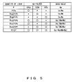
- FIG. 5 shows the operation condition of the filter selection unit provided for the microscope image pickup system according to the second embodiment.
- FIG. 6 is a flowchart for explanation of the operation of the microscope image pickup system according to the second embodiment.
- the same configuration as in the first embodiment is assigned the same reference numeral, and the description is omitted here.
- the microscope image pickup system is provided with ND filters 105a through 105c and filter drive control units 106a through 106c in the microscope 101.
- the PC 152 is also provided with a signal analysis unit 201, a light quantity calculation unit 202, and a filter selection unit 203 in addition to the control software 161, the gain calculation unit 162, the exposure time calculation unit 163, the CPU 164, the signal reception unit 165, the cache memory 166, and the storage memory 167.
- the transmittance of the ND filter 105a is referred to as Na
- the transmittance of the ND filter 105b is referred to as Nb
- the transmittance of the ND filter 105c is referred to as Nc (Na > Nb > Nc).
- the filter drive control unit 106a controls the insert/remove drive of the ND filter 105a
- the filter drive control unit 106b controls the insert/remove drive of the ND filter 105b
- the filter drive control unit 106c controls the insert/remove drive of the ND filter 105c.
- the signal analysis unit 201 calculates the signal value Sig as the highest intensity from the signal value indicating an image received by the signal reception unit 165 in the preview mode. If the expression SL ⁇ Sig ⁇ SH holds where SL and SH respectively indicate predetermined lower limit value SL and upper limit value SH, then the signal value Sig is transmitted to the light quantity calculation unit 202. If the expression Sig ⁇ SL or SH ⁇ Sig holds, the exposure time calculation unit 163 re-calculates the exposure time T and re-issues a capture start instruction to the image pickup device 150.
- the light quantity calculation unit 202 calculates the light quantity P by the following Equation 1 using the gain value G calculated by the gain calculation unit 162, the exposure time T calculated by the exposure time calculation unit 163, the transmittance N of the ND filter 105 inserted during the measurement of light, and the signal value Sig calculated by the signal analysis unit 201.
- the calculated light quantity P is transmitted to the filter selection unit 203.
- P Sig / GTN
- the filter selection unit 203 selects the specific ND filter 105 from among the ND filters 105a through 105c depending on the light quantity P calculated by the light quantity calculation unit 202. That is, the filter selection unit 203 determines the ND filter 105 to be inserted onto the optical path of the exciting light 104 in the preview mode depending on the level of the quantity light P.
- the method of selecting the ND filter 105 is used by dividing the light quantity P by the thresholds Pa, Pb, Pc, Pd, Pe, Pf (Pa ⁇ Pb ⁇ Pc ⁇ Pd ⁇ Pe ⁇ Pf) under the operation conditions shown in FIG. 5 . For example, when the light quantity P satisfies Pc ⁇ P ⁇ Pd, the ND filter 105a and the ND filter 105b are selected.
- the filter selection unit 203 transmits a signal indicating the selected ND filter 105 to the CPU 164, and the CPU 164 controls the operation of the filter drive control unit 106 corresponding to the ND filter 105 indicated by the signal.
- the filter selection unit 203 simultaneously transmits the signal indicating the selected ND filter 105 to the gain calculation unit 162.
- the gain calculation unit 162 calculates a gain value Gp on the basis of the entire transmittance N of the signal indicating the ND filter 105 transmitted from the filter selection unit 203.
- FIG. 6 is a flowchart for explanation of the operation of the microscope image pickup system according to the second embodiment.
- the control software 161 transmits a drive signal to the filter drive control unit 106a through the CPU 164, and inserts the ND filter 105a onto the optical path of the exciting light 104 (S22).
- the control software 161 transmits the initial value of a predetermined exposure time to a control unit for controlling the exposure time of the image pickup element 151 through the CPU 164 to set the exposure time of the image pickup element 151 (S24), and transmits the gain value G calculated by the gain calculation unit 162 to the amplifier 154 to set the gain value G (S25).
- control software 161 transmits a capture start instruction to the image pickup device 150 through the CPU 164 and acquires a captured image for measurement of light (S26).
- control software 161 directs the signal analysis unit 201 to calculate the signal value Sig using the image for the measurement of light obtained in S26 (S27). At this time, the signal analysis unit 201 determines whether or not the signal value Sig is a value within a predetermined range (SL ⁇ Sig ⁇ SH) (S28).
- the control software 161 re-calculates the exposure time by automatically setting the exposure by feedback control of the exposure time calculation unit 163 to set the exposure time (S29) and re-acquire an image for measurement of light (S26).
- the control software 161 directs the light quantity calculation unit 202 to calculate the light quantity P using the gain value G, the exposure time T, the transmittance N, and the signal value Sig (S30).
- control software 161 directs the filter selection unit 203 to select the ND filter 105 corresponding to the light quantity P calculated by the light quantity calculation unit 202 under the operation condition shown in FIG. 5 (S31).
- control software 161 inserts the ND filter 105 selected by the filter selection unit 203 in S31 (S32).
- the control software 161 directs the gain calculation unit 162 to calculate the gain value Gp on the basis of the entire transmittance N of the ND filter 105 selected by the filter selection unit 203 (S33).
- the ND filter 105 is selectively inserted so that the intensity of the exciting light 104 irradiated on the sample 110 in the preview mode can be appropriate depending on the quantity light P entering the image pickup device 150.
- the intensity of the exciting light 104 irradiated on the sample 110 can be appropriately adjusted although using the light source 103 emitting unnecessarily intense exciting light 104, the sample 110 can be appropriately protected against fading.
- the operability of the microscope 101 can be improved.
- the gain value Gp of the amplifier 154 is set higher than the gain value Gs depending on the entire transmittance N of the ND filter 105. Therefore, the intensity of the fluorescence 111 of the sample 110 in the preview mode is equivalent to the intensity of the fluorescence 111 of the sample 110 to be originally observed when the ND filter 105 is removed, thereby successfully maintaining the convenience during observation.
- the gain value Ge of the amplifier 154 is equal to the gain value Gs. Therefore, an image can be recorded in the storage memory 167 with the intensity of the fluorescence 111 of the sample 110 to be originally obtained, thereby storing a clear observed image in the image record mode.
- FIG. 7 shows the internal configuration of the microscope image pickup system according to the third embodiment.
- FIG. 8A shows the operation condition of the preview image quality setting unit provided for the microscope image pickup system according to the third embodiment.
- FIG. 8B shows the operation condition of the image record quality setting unit provided for the microscope image pickup system according to the third embodiment.
- the same configuration as in the first or second embodiment is assigned the same reference numeral, and the description is omitted.
- the microscope image pickup system has the PC 152 further provided with a preview image quality setting unit 210 and an image record quality setting unit 211 in addition to the control software 161, the gain calculation unit 162, the exposure time calculation unit 163, the CPU 164, the signal reception unit 165, the cache memory 166, and the storage memory 167.
- the image quality level of the preview image quality setting unit 210 and the image record quality setting unit 211 is set according to the instruction transmitted from an observer through the control software 161.
- the preview image quality setting unit 210 selects the ND filter 105 to be used in the preview mode from among the ND filters 105a through 105c depending on the image quality level or the fading suppression level set by an observer, and transmits a signal indicating the selected ND filter 105 to the gain calculation unit 162.
- the image record quality setting unit 211 selects the ND filter 105 used in the image record mode from among the ND filters 105a through 105c depending on the image quality level of the fading suppression level set by an observer, and transmits a signal indicating the selected ND filter 105 to the gain calculation unit 162.
- the respective operation conditions of the preview image quality setting unit 210 and the image record quality setting unit 211 are described below with reference to FIGS. 8A and 8B .
- the preview image quality setting unit 210 and the image record quality setting unit 211 select the ND filter 105 to be used depending on the image quality level or the fading suppression level. Since the relationship among the transmittance Na of the ND filter 105a, the transmittance Nb of the ND filter 105b, and the transmittance Nc of the ND filter 105c is expressed by 1 > Na > Nb > Nc, the collation of the gain values set for the gain value Gp and the gain value Ge is expressed by Gs ⁇ Gs/Na ⁇ Gs/Nb ⁇ Gs/Nc. Since the image quality level is inversely proportional to the gain value, it is the image quality level (low, medium, and high) as shown in FIGS.
- the fading suppression level is inversely proportional to the transmittance N of the ND filter 105 it is the fading suppression level (low, medium, and high) as shown in FIGS. 8A and 8B depending on the transmittance N of the ND filter 105 to be used.
- the preview image quality setting unit 210 selects the ND filter 105 depending on the image quality level or the fading suppression level in the preview mode set by an observer.
- the gain calculation unit 162 calculates the gain value Gp depending on the transmittance N of the ND filter 105 to be used. For example, if the observer sets the image quality level in the preview mode as "low”, or the fading suppression level as "high”, the preview image quality setting unit 210 selects the ND filter 105c, and transmits a signal indicating the selected ND filter 105c to the gain calculation unit 162.
- the image record quality setting unit 211 selects the ND filter 105 depending on the image quality level or the fading suppression level in the image record mode set by an observer.
- the gain calculation unit 162 calculates the gain value Ge depending on the transmittance N of the ND filter 105 to be used. For example, when the observer sets the image quality level in the image record mode as "medium”, or the fading suppression level as "medium”, the image record quality setting unit 211 selects the ND filter 105a, and transmits a signal indicating the selected ND filter 105a to the gain calculation unit 162.
- the observer Before entering the preview mode and the image record mode, the observer sets the image quality level or the fading suppression level in the preview mode, and the image quality level or the fading suppression level in the image record mode through the control software 161 in advance.
- the operations of the microscope image pickup system in the subsequent preview mode and the image record mode are the same as those in the first and the second embodiments.
- an observer can select a setting item in the preview mode or the image record mode such as "high image quality level or low fading suppression level”, “low image quality level or high fading suppression level”, “medium image quality level or medium fading suppression level”, etc.
- a setting item in the preview mode or the image record mode such as "high image quality level or low fading suppression level”, “low image quality level or high fading suppression level”, “medium image quality level or medium fading suppression level”, etc.
- the fading can be suppressed appropriately depending on the use or intention of the observer.
- the gain value Gp of the amplifier 154 is set high depending on the transmittance N of the ND filter 105 in the preview mode. Therefore, the intensity of the fluorescence 111 of the sample 110 is equivalent to the intensity of the fluorescence 111 of the sample 110 to be originally observed when the ND filter 105 is removed, thereby successfully maintaining the convenience during observation. Also in the image record mode, the gain value Gp of the amplifier 154 is set higher depending on the transmittance N of the ND filter 105. Therefore, the intensity of the fluorescence 111 of the sample 110 is equivalent to the intensity of the fluorescence 111 of the sample 110 to be originally observed when the ND filter 105 is removed, thereby storing clear observed images.
- the gain value Gp or the gain value Ge of the amplifier 154 of the image pickup device 150 is calculated depending on the switch of the preview mode and the image record mode, but an observer can calculate the gain value Gp or the gain value Ge of the amplifier 154 depending on the insert/remove state of the ND filter 105 by manually inserting/removing the ND filter 105.
- the microscope image pickup system shown in FIG. 9 the microscope image pickup system is configured such that an image pickup device control signal and an ND drive signal are transmitted from the control software 161 to the CPU 164 independently of each other so that the image pickup device 150 and the ND filter 105 can be independently controlled.
- a drive signal of the ND filter 105 is transmitted from the CPU 164 to the filter drive control unit 106, and simultaneously the drive signal is also transmitted to the gain calculation unit 162 to direct the gain calculation unit 162 to calculate the gain value Gp or the gain value Ge.
- still images are recorded in the storage memory 167 in the image record mode
- moving pictures can be recorded in the storage memory 167 in the image record mode using the image pickup device 150 capable of capturing moving pictures.
- the sample 110 can be prevented from being faded by inserting/removing the ND filter 105, but the present invention is not limited to the application, and the fading of the sample 110 can be suppressed by adjusting the pulse width modulation (PWM) of the light source 103, adjusting the turn-on interval of a light emitting diode (LED) as the light source 103, adjusting the power supply voltage of the light source 103, etc.
- PWM pulse width modulation
- LED light emitting diode
- a signal value indicating an image captured by the image pickup device 150 is amplified by raising the gain value of the amplifier 154, but a signal value indicating an image captured by the image pickup device 150 can be amplified by binning, that is, adding and outputting a plurality of signal values. Furthermore, the image pickup device 150 can increase signal values indicating images captured by the image pickup device 150 by extending the exposure time of the image pickup element 151.
- white balance and black balance in the image pickup device 150 can be simultaneously adjusted depending on the intensity o the light source 103 during adjustment of light quantitiy.
Landscapes
- Physics & Mathematics (AREA)
- Chemical & Material Sciences (AREA)
- Analytical Chemistry (AREA)
- General Physics & Mathematics (AREA)
- Optics & Photonics (AREA)
- Engineering & Computer Science (AREA)
- Multimedia (AREA)
- Computer Vision & Pattern Recognition (AREA)
- Microscoopes, Condenser (AREA)
Abstract
Description
- The present invention relates to a microscope image pickup system for use in a fluorescent observation.
- In the medical and biological fields, a fluorescent observation method is used when protein, a gene, etc. in a cell of a living body are observed by a microscope. A fluorescent observation is a method in which a cell of a living body having a fluorescence indicator is irradiated with illumination light (exciting light) having a wavelength of only a specific width so that light having a wavelength (fluorescence) longer than that of the exciting light emitted from the cell of the living body. In addition, there are various capturing methods for capturing and displaying the fluorescence emitted from a cell of a living body, and images such as still images, moving pictures, etc. captured by an electronic image pickup device are not recorded, but preview images of a sample are displayed in real time.
- However, a cell of a living body has the property of being damaged by the irradiation of exciting light, and gradually does no emit fluorescence in the process of the fluorescent observation. The phenomenon is referred to as fading. Therefore, some countermeasures have been devised not to make the sample of the cell of a living body faded.
- For example, there is a microscope image pickup system for open/close controlling a cutoff device for a light source of a microscope depending on the operation mode of the image pickup device (for example, refer to Japanese Published Patent Application No.
2005-316036 - However, the above-mentioned microscope image pickup system has no suppressing means against the fading of a sample during display of a preview image. Normally, preview images are widely used in placing a sample in focus, aligning an observed portion, observing a sample in real time, etc., and a long time is required during display of preview images. Therefore, in the microscope image pickup system, fading of a sample during display of a preview image is specifically considered.
- The present invention aims at providing a microscope image pickup system capable of suppressing the fading of a sample during display of a preview image.
- To solve the above-mentioned problem, the present invention has the following configuration.
- The microscope image pickup system according to the present invention includes: a light source for emitting illumination light irradiating a test object; an object lens mounted opposite the test object; a display device; a record device; a capture device for performing a preview mode in which an image of the test object obtained by the object lens is repeatedly captured and a plurality of captured images are continuously displayed on the display device, or an image record mode in which the image of the test object is captured and the captured image is recorded on the record device; an illumination light amount control device for controlling an amount of light of the illumination light; and a system control device for controlling an operation of the illumination light amount control device depending on the preview mode or the image record mode performed by the capture device.
- The system control device can also be configured to control the operation of the capture device depending on the preview mode or the image record mode performed by the capture device.
- In addition, the system control device can further be configured to control the operation of the capture device depending on the operation of the illumination light amount control device.
- The microscope image pickup system can be configured to include a calculation device for calculating an amount of light of the illumination light in the preview mode, and the system control device controls the operation of the illumination light amount control device and the operation of the capture device depending on the amount of light calculated by the calculation device.
- The microscope image pickup system can be configured to include an image quality adjustment device for adjusting the quality of the image at a plurality of stages, and the system control device controls the operation of the illumination light amount adjustment device and the operation of the capture device depending on the combination of the quality at one of a plurality of stages adjusted by the image quality adjustment device and the preview mode or the image record mode performed by the capture device.
- The microscope image pickup system according to the present invention includes: a light source for emitting illumination light irradiating a test object; an object lens mounted opposite the test object; a capture device for capturing an image of the test object by the object lens; an illumination light amount control device for controlling the amount of light of the illumination light; and a system control device for controlling the operation of the capture device depending on the operation of the illumination light amount control device.
- The operation of the illumination light amount control device can be adjusting the entire transmittance of one or more darkening filters provided between the test object and the light source or the intensity of the illumination light of the light source.
- The operation of the capture device can be adjusting the amplification rate of the signal value indicating the image, exposure time, white balance, or black balance.
-
-
FIG. 1 shows the microscope image pickup system according to the first embodiment of the present invention; -
FIG. 2 shows the internal configuration of the microscope image pickup system according to the first embodiment; -
FIG. 3 is a flowchart for explanation of the operation of the microscope image pickup system according to the first embodiment; -
FIG. 4 shows the internal configuration of the microscope image pickup system according to the second embodiment; -
FIG. 5 shows the operation condition of the filter selection unit provided for the microscope image pickup system according to the second embodiment; -
FIG. 6 is a flowchart for explanation of the operation of the microscope image pickup system according to the second embodiment; -
FIG. 7 shows the internal configuration of the microscope image pickup system according to the third embodiment; -
FIG. 8A shows the operation condition of the preview image quality setting unit provided for the microscope image pickup system according to the third embodiment; -
FIG. 8B shows the operation condition of the image record quality setting unit provided for the microscope image pickup system according to the third embodiment; -
FIG. 9 shows the internal configuration of the microscope image pickup system according to another embodiment. - The embodiments of the present invention are described below with reference to the attached drawings.
-
FIG. 1 shows the microscope image pickup system according to the first embodiment of the present invention.FIG. 2 shows the internal configuration of the microscope image pickup system according to the first embodiment. - First, the configuration of the microscope image pickup system according to the first embodiment is described below with reference to
FIGS. 1 and2 . -
FIG. 1 or2 shows amicroscope 101, anillumination device 102 for emitting exciting light having only a specific wavelength, and alight source 103.Exciting light 104 emitted from thelight source 103 in theillumination device 102 is irradiated into the inside of themicroscope 101.FIGS. 1 and2 also show a darkening filter 105 (hereinafter referred to as an ND filter), and a filterdrive control unit 106. TheND filter 105 is drive controlled by the filterdrive control unit 106, and is selectively inserted/removed on the optical path of theexciting light 104.FIG. 1 also shows adichroic mirror 107. Thedichroic mirror 107 is provided with a mirror for reflecting theexciting light 104 and transmitting thefluorescence 111 described later. Theexciting light 104 is reflected by thedichroic mirror 107 and passes through anobject lens 108, and then irradiates a sample 110 (test object) on astage 109. Thesample 110 receives theexciting light 104 and emitsfluorescence 111 having a wavelength longer than that of theexciting light 104. Thefluorescence 111 passes through theobject lens 108, thedichroic mirror 107, and abarrel 112, and then introduced into animage pickup element 151 in animage pickup device 150. -
FIGS. 1 and2 also show a PC 152 and amonitor 153. The PC 152 and theimage pickup device 150 are electrically connected to each other, and the PC 152 controls each unit of theimage pickup device 150 bycontrol software 161 through aCPU 164. Similarly, the PC 152 and the filterdrive control unit 106 are electrically connected to each other, and the PC 152 controls the operation of the filterdrive control unit 106 by thecontrol software 161 through theCPU 164. - The
image pickup device 150 is provided with theimage pickup element 151, anamplifier 154, and an A/D converter 155. Theamplifier 154 multiplies a signal value indicating an image transmitted from theimage pickup element 151 by a predetermined gain value (amplification rate) for amplification. Thecontrol software 161 in the PC 152 controls theimage pickup device 150, the filterdrive control unit 106, and again calculation unit 162 by the operation input from an observer. Thegain calculation unit 162 calculates the gain value of theamplifier 154 according to a signal from thecontrol software 161. The exposuretime calculation unit 163 calculates the exposure time of theimage pickup element 151. TheCPU 164 integrally controls each unit according to a signal from thecontrol software 161. Asignal reception unit 165 receives a signal value indicating an image transmitted from theimage pickup device 150, and allocates the signal value indicating an image tocache memory 166 orstorage memory 167 in a preview mode or an image record mode described later. Thecache memory 166 has a memory area for storing a signal value indicating one image. Thestorage memory 167 has a memory area for storing plural still images and moving pictures. - Described below are the preview mode and the image record mode used in the microscope image pickup system according to the present embodiment. The preview mode or the image record mode is performed by the
control software 161 by an observer issuing an instruction to thecontrol software 161. - The preview mode is a function in which an image is fetched to the
image pickup device 150 continuously in time, and is continuously displayed on themonitor 153. The order of the processes of a signal value indicating an image in the preview mode is described below. First, the signal value indicating an image obtained by theimage pickup element 151 is amplified by theamplifier 154, converted into a digital value by the A/D converter 155, and transmitted to thesignal reception unit 165. Next, the signal value indicating the image is transmitted from thesignal reception unit 165 to thecache memory 166, and temporarily stored therein. A series of the processes are performed continuously in time, and the image stored in thecache memory 166 is updated at any time. The image obtained in thecache memory 166 is displayed continuously in time on themonitor 153. - The image record mode is a function in which a still image captured by the
image pickup device 150 is stored. Described below is the order of the processes of the signal value indicating an image in the image record mode. First, the signal value indicating the image obtained by theimage pickup element 151 is amplified by theamplifier 154, converted into a digital value by the A/D converter 155, and transmitted to thesignal reception unit 165. Next, the signal value indicating the image is transmitted from thesignal reception unit 165 to thestorage memory 167, and stored therein. Although the image capturing operations are performed any number of times, the images recorded in thestorage memory 167 are not updated, but the images are stored in different memory stores. -
FIG. 3 is a flowchart for explanation of the operation of the microscope image pickup system according to the first embodiment. The feature of the microscope image pickup system according to the first embodiment is to insert theND filter 105 into the optical path of theexciting light 104 in the preview mode, and remove theND filter 105 from the optical path of theexciting light 104 in the image record mode. - First, when an instruction to enter the preview mode is issued to the
control software 161 by, for example, pressing a preview start button by an observer (S1), thecontrol software 161 transmits a drive signal to the filterdrive control unit 106 through theCPU 164, and inserts theND filter 105 into the optical path of the exciting light 104 (S2). - Next, the
control software 161 directs thegain calculation unit 162 to calculate the gain value Gp in the preview mode and the gain value Ge in the image record mode (S3). Assume that the transmittance of theND filter 105 is N, and the gain of theamplifier 154 defined by an observer by thecontrol software 161 is Gs, the gain value Gp in the preview mode is calculated by Gp = Gs/N, and the gain value Ge in the image record mode is Ge = Gs. - Next, the
control software 161 transmits the initial value of a predetermined exposure time to a control unit for controlling the exposure time of theimage pickup element 151 through theCPU 164, sets the exposure time of the image pickup element 151 (S4), transmits the gain value Gp calculated by thegain calculation unit 162 to theamplifier 154, and sets the gain value Gp (S5). - Then, the
control software 161 transmits a capture start instruction again to theimage pickup device 150 through theCPU 164, and acquires an image (S6). - Next, the
control software 161 determines the exposure time in the preview mode (S7). The exposure time determined at this time is determined by an observer using thecontrol software 161 or calculated by the exposuretime calculation unit 163 using the image transmitted from thesignal reception unit 165. - Next, the
control software 161 transmits a capture start instruction to theimage pickup device 150 through theCPU 164, and acquires an image (S6). In the preview mode, the processes in S6 and S7 are repeated. After the first process in S7, the image record mode can be used. - When the observer issues an instruction to enter the image record mode to the
control software 161 by, for example, pressing an image storage button (S8), thecontrol software 161 transmits a drive signal to the filterdrive control unit 106 through theCPU 164, and removes theND filter 105 from the optical path of the exciting light 104 (S9). - Next, the
control software 161 transmits the exposure time determined in the preview mode in S7 to the control unit for controlling the exposure time of theimage pickup element 151 through theCPU 164 to set the exposure time of theimage pickup element 151, and transmits the gain value Ge calculated by thegain calculation unit 162 to theamplifier 154 to set the gain value Ge (S10). - Then, the
control software 161 transmits a capture start instruction to theimage pickup device 150 through theCPU 164, acquires an image, and records the image in the storage memory 167 (S11). - After a capturing operation is completed, the
control software 161 transmits a drive signal again to the filterdrive control unit 106 through theCPU 164, directs theND filter 105 to enter the optical path of the exciting light 104 (S12), and returns control to the preview mode (S6, S7). - In the microscope image pickup system according to the first embodiment, the
ND filter 105 enters the optical path of theexciting light 104 in the preview mode, and the intensity of theexciting light 104 irradiated onto thesample 110 can be reduced. Thus, the fading of thesample 110 in the preview mode can be suppressed. - According to the microscope image pickup system of the first embodiment, when the
ND filter 105 is inserted in the preview mode, the gain value Gp of theamplifier 154 is set higher than the gain value Gs depending on the transmittance N of theND filter 105. Therefore, the intensity of thefluorescence 111 of thesample 110 in the preview mode is equal to the intensity of thefluorescence 111 of thesample 110 originally observed when theND filter 105 is removed, thereby guaranteeing the convenience during observation. In addition, since the gain value Ge of theamplifier 154 is equal to the gain value Gs when theND filter 105 is removed in the image record mode, the image can be recorded in thestorage memory 167 with the intensity of thefluorescence 111 of the originally observedsample 110, thereby storing a clear observed image in the image record mode. - Described next is the microscope image pickup system according to the second embodiment.
-
FIG. 4 shows the internal configuration of the microscope image pickup system according to the second embodiment.FIG. 5 shows the operation condition of the filter selection unit provided for the microscope image pickup system according to the second embodiment.FIG. 6 is a flowchart for explanation of the operation of the microscope image pickup system according to the second embodiment. InFIG. 4 , the same configuration as in the first embodiment is assigned the same reference numeral, and the description is omitted here. - As shown in
FIG. 4 , the microscope image pickup system according to the second embodiment is provided withND filters 105a through 105c and filterdrive control units 106a through 106c in themicroscope 101. Additionally, thePC 152 is also provided with asignal analysis unit 201, a lightquantity calculation unit 202, and afilter selection unit 203 in addition to thecontrol software 161, thegain calculation unit 162, the exposuretime calculation unit 163, theCPU 164, thesignal reception unit 165, thecache memory 166, and thestorage memory 167. In addition, the transmittance of theND filter 105a is referred to as Na, the transmittance of theND filter 105b is referred to as Nb, and the transmittance of theND filter 105c is referred to as Nc (Na > Nb > Nc). - The filter
drive control unit 106a controls the insert/remove drive of theND filter 105a, the filterdrive control unit 106b controls the insert/remove drive of theND filter 105b, and the filterdrive control unit 106c controls the insert/remove drive of theND filter 105c. - The
signal analysis unit 201 calculates the signal value Sig as the highest intensity from the signal value indicating an image received by thesignal reception unit 165 in the preview mode. If the expression SL ≤ Sig ≤ SH holds where SL and SH respectively indicate predetermined lower limit value SL and upper limit value SH, then the signal value Sig is transmitted to the lightquantity calculation unit 202. If the expression Sig < SL or SH < Sig holds, the exposuretime calculation unit 163 re-calculates the exposure time T and re-issues a capture start instruction to theimage pickup device 150. - The light
quantity calculation unit 202 calculates the light quantity P by the followingEquation 1 using the gain value G calculated by thegain calculation unit 162, the exposure time T calculated by the exposuretime calculation unit 163, the transmittance N of theND filter 105 inserted during the measurement of light, and the signal value Sig calculated by thesignal analysis unit 201. The calculated light quantity P is transmitted to thefilter selection unit 203.
- The
filter selection unit 203 selects thespecific ND filter 105 from among theND filters 105a through 105c depending on the light quantity P calculated by the lightquantity calculation unit 202. That is, thefilter selection unit 203 determines theND filter 105 to be inserted onto the optical path of theexciting light 104 in the preview mode depending on the level of the quantity light P. The method of selecting theND filter 105 is used by dividing the light quantity P by the thresholds Pa, Pb, Pc, Pd, Pe, Pf (Pa < Pb < Pc < Pd < Pe < Pf) under the operation conditions shown inFIG. 5 . For example, when the light quantity P satisfies Pc ≤ P < Pd, theND filter 105a and theND filter 105b are selected. - In addition, the
filter selection unit 203 transmits a signal indicating the selectedND filter 105 to theCPU 164, and theCPU 164 controls the operation of the filterdrive control unit 106 corresponding to theND filter 105 indicated by the signal. Thefilter selection unit 203 simultaneously transmits the signal indicating the selectedND filter 105 to thegain calculation unit 162. Thegain calculation unit 162 calculates a gain value Gp on the basis of the entire transmittance N of the signal indicating theND filter 105 transmitted from thefilter selection unit 203. For example, when the signals indicating theND filter 105a and theND filter 105b are transmitted from thefilter selection unit 203 to thegain calculation unit 162, thegain calculation unit 162 calculates the gain value Gp by the equation Gp = Gs / (Na * Nb) as shown inFIG. 5 . -
FIG. 6 is a flowchart for explanation of the operation of the microscope image pickup system according to the second embodiment. - First, when an observer issues an instruction to use the preview mode to the
control software 161 by, for example, pressing the preview start button etc. (S21), thecontrol software 161 transmits a drive signal to the filterdrive control unit 106a through theCPU 164, and inserts theND filter 105a onto the optical path of the exciting light 104 (S22). - Next, the
control software 161 directs thegain calculation unit 162 to calculate the gain value G in the same method as in the first embodiment (S23). That is, the gain value G is obtained by G = Gs / Na. - The
control software 161 transmits the initial value of a predetermined exposure time to a control unit for controlling the exposure time of theimage pickup element 151 through theCPU 164 to set the exposure time of the image pickup element 151 (S24), and transmits the gain value G calculated by thegain calculation unit 162 to theamplifier 154 to set the gain value G (S25). - Next, the
control software 161 transmits a capture start instruction to theimage pickup device 150 through theCPU 164 and acquires a captured image for measurement of light (S26). - Then, the
control software 161 directs thesignal analysis unit 201 to calculate the signal value Sig using the image for the measurement of light obtained in S26 (S27). At this time, thesignal analysis unit 201 determines whether or not the signal value Sig is a value within a predetermined range (SL ≤ Sig ≤ SH) (S28). - When the signal value Sig is out of the range (NO in S28), the
control software 161 re-calculates the exposure time by automatically setting the exposure by feedback control of the exposuretime calculation unit 163 to set the exposure time (S29) and re-acquire an image for measurement of light (S26). - On the other hand, when it is determined that the signal value Sig is within a predetermined range (YES in S28), the
control software 161 directs the lightquantity calculation unit 202 to calculate the light quantity P using the gain value G, the exposure time T, the transmittance N, and the signal value Sig (S30). - Next, the
control software 161 directs thefilter selection unit 203 to select theND filter 105 corresponding to the light quantity P calculated by the lightquantity calculation unit 202 under the operation condition shown inFIG. 5 (S31). - Next, the
control software 161 inserts theND filter 105 selected by thefilter selection unit 203 in S31 (S32). - The
control software 161 directs thegain calculation unit 162 to calculate the gain value Gp on the basis of the entire transmittance N of theND filter 105 selected by the filter selection unit 203 (S33). - Afterwards, the operations in the preview mode and the image record mode similar to those in S5 through S12 according to the first embodiment are performed.
- According to the microscope image pickup system of the second embodiment, the
ND filter 105 is selectively inserted so that the intensity of theexciting light 104 irradiated on thesample 110 in the preview mode can be appropriate depending on the quantity light P entering theimage pickup device 150. Thus, since the intensity of theexciting light 104 irradiated on thesample 110 can be appropriately adjusted although using thelight source 103 emitting unnecessarily intenseexciting light 104, thesample 110 can be appropriately protected against fading. - According to the microscope image pickup system of the second embodiment, since the operation conditions for the selection of the
ND filter 105, the calculation of a gain value Gp, etc. are automatically adjusted without specific operations of an observer, the operability of themicroscope 101 can be improved. - In addition, according to the microscope image pickup system of the second embodiment, as with the microscope image pickup system of the first embodiment, when the
ND filter 105 is inserted in the preview mode, the gain value Gp of theamplifier 154 is set higher than the gain value Gs depending on the entire transmittance N of theND filter 105. Therefore, the intensity of thefluorescence 111 of thesample 110 in the preview mode is equivalent to the intensity of thefluorescence 111 of thesample 110 to be originally observed when theND filter 105 is removed, thereby successfully maintaining the convenience during observation. In addition, when theND filter 105 is removed in the image record mode, the gain value Ge of theamplifier 154 is equal to the gain value Gs. Therefore, an image can be recorded in thestorage memory 167 with the intensity of thefluorescence 111 of thesample 110 to be originally obtained, thereby storing a clear observed image in the image record mode. - Described next is the microscope image pickup system according to the third embodiment of the present invention.
-
FIG. 7 shows the internal configuration of the microscope image pickup system according to the third embodiment.FIG. 8A shows the operation condition of the preview image quality setting unit provided for the microscope image pickup system according to the third embodiment.FIG. 8B shows the operation condition of the image record quality setting unit provided for the microscope image pickup system according to the third embodiment. InFIG. 7 , the same configuration as in the first or second embodiment is assigned the same reference numeral, and the description is omitted. - As shown in
FIG. 7 , the microscope image pickup system according to the third embodiment has thePC 152 further provided with a preview imagequality setting unit 210 and an image recordquality setting unit 211 in addition to thecontrol software 161, thegain calculation unit 162, the exposuretime calculation unit 163, theCPU 164, thesignal reception unit 165, thecache memory 166, and thestorage memory 167. The image quality level of the preview imagequality setting unit 210 and the image recordquality setting unit 211 is set according to the instruction transmitted from an observer through thecontrol software 161. - The preview image
quality setting unit 210 selects theND filter 105 to be used in the preview mode from among theND filters 105a through 105c depending on the image quality level or the fading suppression level set by an observer, and transmits a signal indicating the selectedND filter 105 to thegain calculation unit 162. - The image record
quality setting unit 211 selects theND filter 105 used in the image record mode from among theND filters 105a through 105c depending on the image quality level of the fading suppression level set by an observer, and transmits a signal indicating the selectedND filter 105 to thegain calculation unit 162. - The respective operation conditions of the preview image
quality setting unit 210 and the image recordquality setting unit 211 are described below with reference toFIGS. 8A and8B . - The preview image
quality setting unit 210 and the image recordquality setting unit 211 select theND filter 105 to be used depending on the image quality level or the fading suppression level. Since the relationship among the transmittance Na of theND filter 105a, the transmittance Nb of theND filter 105b, and the transmittance Nc of theND filter 105c is expressed by 1 > Na > Nb > Nc, the collation of the gain values set for the gain value Gp and the gain value Ge is expressed by Gs < Gs/Na < Gs/Nb < Gs/Nc. Since the image quality level is inversely proportional to the gain value, it is the image quality level (low, medium, and high) as shown inFIGS. 8A and8B depending on the gain values set. Similarly, since the fading suppression level is inversely proportional to the transmittance N of theND filter 105 it is the fading suppression level (low, medium, and high) as shown inFIGS. 8A and8B depending on the transmittance N of theND filter 105 to be used. - The preview image
quality setting unit 210 selects theND filter 105 depending on the image quality level or the fading suppression level in the preview mode set by an observer. Thegain calculation unit 162 calculates the gain value Gp depending on the transmittance N of theND filter 105 to be used. For example, if the observer sets the image quality level in the preview mode as "low", or the fading suppression level as "high", the preview imagequality setting unit 210 selects theND filter 105c, and transmits a signal indicating the selectedND filter 105c to thegain calculation unit 162. Thegain calculation unit 162 calculates the gain value Gp = Gs/Nc, and transmits the calculated gain value Gp to theCPU 164. - Similarly, the image record
quality setting unit 211 selects theND filter 105 depending on the image quality level or the fading suppression level in the image record mode set by an observer. Thegain calculation unit 162 calculates the gain value Ge depending on the transmittance N of theND filter 105 to be used. For example, when the observer sets the image quality level in the image record mode as "medium", or the fading suppression level as "medium", the image recordquality setting unit 211 selects theND filter 105a, and transmits a signal indicating the selectedND filter 105a to thegain calculation unit 162. Thegain calculation unit 162 calculates the gain value Gp = Gs/Na, and transmits the calculated gain value Gp to theCPU 164. - Before entering the preview mode and the image record mode, the observer sets the image quality level or the fading suppression level in the preview mode, and the image quality level or the fading suppression level in the image record mode through the
control software 161 in advance. The operations of the microscope image pickup system in the subsequent preview mode and the image record mode are the same as those in the first and the second embodiments. - In the microscope image pickup system according to the third embodiment, an observer can select a setting item in the preview mode or the image record mode such as "high image quality level or low fading suppression level", "low image quality level or high fading suppression level", "medium image quality level or medium fading suppression level", etc. Thus, the fading can be suppressed appropriately depending on the use or intention of the observer.
- In addition, according to the microscope image pickup system of the third embodiment, the gain value Gp of the
amplifier 154 is set high depending on the transmittance N of theND filter 105 in the preview mode. Therefore, the intensity of thefluorescence 111 of thesample 110 is equivalent to the intensity of thefluorescence 111 of thesample 110 to be originally observed when theND filter 105 is removed, thereby successfully maintaining the convenience during observation. Also in the image record mode, the gain value Gp of theamplifier 154 is set higher depending on the transmittance N of theND filter 105. Therefore, the intensity of thefluorescence 111 of thesample 110 is equivalent to the intensity of thefluorescence 111 of thesample 110 to be originally observed when theND filter 105 is removed, thereby storing clear observed images. - In the above-mentioned embodiments, a number of variations can be realized within the scope of the microscope image pickup system of the present invention.
- That is, in the above-mentioned embodiments, the gain value Gp or the gain value Ge of the
amplifier 154 of theimage pickup device 150 is calculated depending on the switch of the preview mode and the image record mode, but an observer can calculate the gain value Gp or the gain value Ge of theamplifier 154 depending on the insert/remove state of theND filter 105 by manually inserting/removing theND filter 105. For example, as the microscope image pickup system shown inFIG. 9 , the microscope image pickup system is configured such that an image pickup device control signal and an ND drive signal are transmitted from thecontrol software 161 to theCPU 164 independently of each other so that theimage pickup device 150 and theND filter 105 can be independently controlled. Then, a drive signal of theND filter 105 is transmitted from theCPU 164 to the filterdrive control unit 106, and simultaneously the drive signal is also transmitted to thegain calculation unit 162 to direct thegain calculation unit 162 to calculate the gain value Gp or the gain value Ge. With the configuration, as in the above-mentioned embodiments, a clear preview image can be acquired with the fading suppressed and the gain value Gp of theamplifier 154 raised by inserting theND filter 105 in the preview mode, and a clear storage images can be acquired by removing theND filter 105 and reducing the gain value Ge of theamplifier 154 in the image record mode. - In the above-mentioned embodiments, still images are recorded in the
storage memory 167 in the image record mode, but moving pictures can be recorded in thestorage memory 167 in the image record mode using theimage pickup device 150 capable of capturing moving pictures. - In the above-mentioned embodiments, the
sample 110 can be prevented from being faded by inserting/removing theND filter 105, but the present invention is not limited to the application, and the fading of thesample 110 can be suppressed by adjusting the pulse width modulation (PWM) of thelight source 103, adjusting the turn-on interval of a light emitting diode (LED) as thelight source 103, adjusting the power supply voltage of thelight source 103, etc. - In addition, according to the above-mentioned embodiments, a signal value indicating an image captured by the
image pickup device 150 is amplified by raising the gain value of theamplifier 154, but a signal value indicating an image captured by theimage pickup device 150 can be amplified by binning, that is, adding and outputting a plurality of signal values. Furthermore, theimage pickup device 150 can increase signal values indicating images captured by theimage pickup device 150 by extending the exposure time of theimage pickup element 151. - Additionally, in the above-mentioned embodiments, white balance and black balance in the
image pickup device 150 can be simultaneously adjusted depending on the intensity o thelight source 103 during adjustment of light quantitiy.
Claims (17)
- A microscope image pickup system, comprising:a light source (103) emitting illumination light (104) irradiating a test object (110);an object lens (108) mounted opposite the test object (110);a display device (153);a record device (167);a capture device (150, 152) performing a preview mode in which an image of the test object (110) obtained by the object lens (108) is repeatedly captured and a plurality of captured images are continuously displayed on the display device (153), or an image record mode in which the image of the test object (110) is captured and the captured image is recorded on the record device (167);an illumination light amount control device (106) controlling an amount of light of the illumination light (104); anda system control device (161) controlling an operation of the illumination light amount control device (106) depending on the preview mode or the image record mode performed by the capture device (150, 152).
- The microscope image pickup system according to claim 1, wherein
the system control device (161) controls an operation of the capture device (150, 152) depending on the preview mode or the image record mode performed by the capture device (150, 152). - The microscope image pickup system according to claim 1, wherein
the system control device (161) controls an operation of the capture device (150, 152) depending on an operation of the illumination light amount control device (106). - The microscope image pickup system according to claim 1, further comprising
a calculation device (202) calculating an amount of light of the illumination light (104) in the preview mode, wherein
the system control device (161) controls an operation of the illumination light amount control device (106) and an operation of the capture device (150, 152) depending on the amount of light calculated by the calculation device (202). - The microscope image pickup system according to claim 1, further comprising
an image quality adjustment device (210, 211) adjusting quality of an image at a plurality of stages, wherein
the system control device (161) controls an operation of the illumination light amount adjustment device (106) and an operation of the capture device (150, 152) depending on a combination of quality at one of a plurality of stages adjusted by the image quality adjustment device (210, 211) and the preview mode or the image record mode performed by the capture device (150, 152). - A microscope image pickup system, comprising:a light source (103) emitting illumination light (104) irradiating a test object (110);an object lens (108) mounted opposite the test object (110);a capture device (150, 152) capturing an image of the test object (110) by the object lens (108);an illumination light amount control device (106) controlling an amount of light of the illumination light (104); anda system control device (161) controlling an operation of the capture device (150, 152) depending on an operation of the illumination light amount control device (106).
- The microscope image pickup system according to claim 1, wherein
an operation of the illumination light amount control device (106) is adjusting entire transmittance of one or more darkening filters (105) provided between the test object (110) and the light source (103) or intensity of the illumination light (104) of the light source (103). - The microscope image pickup system according to claim 2, wherein
an operation of the illumination light amount control device (106) is adjusting entire transmittance of one or more darkening filters (105) provided between the test object (110) and the light source (103) or intensity of the illumination light (104) of the light source (103). - The microscope image pickup system according to claim 3, wherein
an operation of the illumination light amount control device (106) is adjusting entire transmittance of one or more darkening filters (105) provided between the test object (110) and the light source (103) or intensity of the illumination light (104) of the light source (103). - The microscope image pickup system according to claim 4, wherein
an operation of the illumination light amount control device (106) is adjusting entire transmittance of one or more darkening filters (105) provided between the test object (110) and the light source (103) or intensity of the illumination light (104) of the light source (103). - The microscope image pickup system according to claim 5, wherein
an operation of the illumination light amount control device (106) is adjusting entire transmittance of one or more darkening filters (105) provided between the test object (110) and the light source (103) or intensity of the illumination light (104) of the light source (103). - The microscope image pickup system according to claim 6, wherein
an operation of the illumination light amount control device (106) is adjusting entire transmittance of one or more darkening filters (105) provided between the test object (110) and the light source (103) or intensity of the illumination light (104) of the light source (103). - The microscope image pickup system according to claim 2, wherein
an operation of the capture device (150, 152) is adjusting an amplification rate of a signal value indicating the image, exposure time, white balance, or black balance. - The microscope image pickup system according to claim 3, wherein
an operation of the capture device (150, 152) is adjusting an amplification rate of a signal value indicating the image, exposure time, white balance, or black balance. - The microscope image pickup system according to claim 4, wherein
an operation of the capture device (150, 152) is adjusting an amplification rate of a signal value indicating the image, exposure time, white balance, or black balance. - The microscope image pickup system according to claim 5, wherein
an operation of the capture device (150, 152) is adjusting an amplification rate of a signal value indicating the image, exposure time, white balance, or black balance. - The microscope image pickup system according to claim 6, wherein
an operation of the capture device (150, 152) is adjusting an amplification rate of a signal value indicating the image, exposure time, white balance, or black balance.
Priority Applications (1)
| Application Number | Priority Date | Filing Date | Title |
|---|---|---|---|
| EP08021188A EP2194413A1 (en) | 2008-12-05 | 2008-12-05 | Microscope image pickup system |
Applications Claiming Priority (1)
| Application Number | Priority Date | Filing Date | Title |
|---|---|---|---|
| EP08021188A EP2194413A1 (en) | 2008-12-05 | 2008-12-05 | Microscope image pickup system |
Publications (1)
| Publication Number | Publication Date |
|---|---|
| EP2194413A1 true EP2194413A1 (en) | 2010-06-09 |
Family
ID=40551441
Family Applications (1)
| Application Number | Title | Priority Date | Filing Date |
|---|---|---|---|
| EP08021188A Ceased EP2194413A1 (en) | 2008-12-05 | 2008-12-05 | Microscope image pickup system |
Country Status (1)
| Country | Link |
|---|---|
| EP (1) | EP2194413A1 (en) |
Citations (2)
| Publication number | Priority date | Publication date | Assignee | Title |
|---|---|---|---|---|
| US20060171023A1 (en) | 2005-02-03 | 2006-08-03 | Olympus Corporation | Image acquisition apparatus for use with a microscope, an image recording system that uses the image acquisition appartatus, and an image storage method |
| US20060204236A1 (en) | 2005-02-16 | 2006-09-14 | Nikon Corporation | Intermittent photo-taking device and microscope system having the same device |
-
2008
- 2008-12-05 EP EP08021188A patent/EP2194413A1/en not_active Ceased
Patent Citations (2)
| Publication number | Priority date | Publication date | Assignee | Title |
|---|---|---|---|---|
| US20060171023A1 (en) | 2005-02-03 | 2006-08-03 | Olympus Corporation | Image acquisition apparatus for use with a microscope, an image recording system that uses the image acquisition appartatus, and an image storage method |
| US20060204236A1 (en) | 2005-02-16 | 2006-09-14 | Nikon Corporation | Intermittent photo-taking device and microscope system having the same device |
Similar Documents
| Publication | Publication Date | Title |
|---|---|---|
| US8233039B2 (en) | Microscope image pickup system | |
| US10595708B2 (en) | Control device for endoscope system, endoscope system, and control method for endoscope system | |
| JP2007054342A (en) | Electronic endoscope system | |
| US20070285771A1 (en) | Endoscope system | |
| JP2006034415A (en) | Electronic endoscope system | |
| EP1884183A1 (en) | Image processing device, endoscope device, and color balance adjusting method | |
| JP4566754B2 (en) | Image processing device | |
| US8436320B2 (en) | Fluorescence detecting apparatus, and fluorescence detecting method | |
| EP1417924B1 (en) | Ophthalmologic image taking apparatus | |
| JP4814529B2 (en) | Image processing device | |
| EP2128678B1 (en) | Observation device and wavelength limiting filter | |
| US11086115B2 (en) | Microscope device, viewing method, and control program | |
| JP2008259591A (en) | Light source device for fluorescence observation and fluorescence observation instrument using the same | |
| CN113155791A (en) | Method and device for high-resolution imaging of structures marked with fluorescent markings of a sample | |
| JP2005204958A (en) | Electronic endoscope apparatus and system capable of autofluorescence observation | |
| EP2589328A1 (en) | Image processing apparatus and image processing method | |
| EP2194413A1 (en) | Microscope image pickup system | |
| JP4694311B2 (en) | Endoscope processor, image switching program, and fluorescence endoscope system | |
| JP4520283B2 (en) | Electronic endoscope system | |
| JP2005204905A (en) | Electronic endoscope apparatus having light irradiation control function | |
| WO2013005765A1 (en) | Microscope device | |
| JP2006020788A (en) | Electronic endoscope apparatus and system capable of autofluorescence observation | |
| JP2009095538A (en) | Electronic endoscope of endoscope apparatus | |
| EP2988490B1 (en) | Photographing apparatus and method | |
| JP6184919B2 (en) | Imaging apparatus and method |
Legal Events
| Date | Code | Title | Description |
|---|---|---|---|
| PUAI | Public reference made under article 153(3) epc to a published international application that has entered the european phase |
Free format text: ORIGINAL CODE: 0009012 |
|
| 17P | Request for examination filed |
Effective date: 20090916 |
|
| AK | Designated contracting states |
Kind code of ref document: A1 Designated state(s): AT BE BG CH CY CZ DE DK EE ES FI FR GB GR HR HU IE IS IT LI LT LU LV MC MT NL NO PL PT RO SE SI SK TR |
|
| AX | Request for extension of the european patent |
Extension state: AL BA MK RS |
|
| 17Q | First examination report despatched |
Effective date: 20101028 |
|
| AKX | Designation fees paid |
Designated state(s): DE |
|
| STAA | Information on the status of an ep patent application or granted ep patent |
Free format text: STATUS: THE APPLICATION HAS BEEN REFUSED |
|
| 18R | Application refused |
Effective date: 20121025 |