EP2194398A1 - Ultrasound diagnosis apparatus - Google Patents
Ultrasound diagnosis apparatus Download PDFInfo
- Publication number
- EP2194398A1 EP2194398A1 EP09014375A EP09014375A EP2194398A1 EP 2194398 A1 EP2194398 A1 EP 2194398A1 EP 09014375 A EP09014375 A EP 09014375A EP 09014375 A EP09014375 A EP 09014375A EP 2194398 A1 EP2194398 A1 EP 2194398A1
- Authority
- EP
- European Patent Office
- Prior art keywords
- reception
- receiving unit
- diagnosis apparatus
- ultrasound diagnosis
- peak
- Prior art date
- Legal status (The legal status is an assumption and is not a legal conclusion. Google has not performed a legal analysis and makes no representation as to the accuracy of the status listed.)
- Withdrawn
Links
- 238000002604 ultrasonography Methods 0.000 title claims description 36
- 238000003745 diagnosis Methods 0.000 title claims description 22
- 230000005540 biological transmission Effects 0.000 claims description 11
- 238000000034 method Methods 0.000 description 26
- 230000008569 process Effects 0.000 description 20
- 238000010586 diagram Methods 0.000 description 13
- 230000000875 corresponding effect Effects 0.000 description 12
- 230000008901 benefit Effects 0.000 description 6
- 230000035945 sensitivity Effects 0.000 description 6
- 230000009467 reduction Effects 0.000 description 5
- 230000006872 improvement Effects 0.000 description 3
- 239000000523 sample Substances 0.000 description 3
- 230000015572 biosynthetic process Effects 0.000 description 2
- 230000008859 change Effects 0.000 description 2
- 238000006243 chemical reaction Methods 0.000 description 1
- 230000006835 compression Effects 0.000 description 1
- 238000007906 compression Methods 0.000 description 1
- 230000001276 controlling effect Effects 0.000 description 1
- 230000002596 correlated effect Effects 0.000 description 1
- 230000003247 decreasing effect Effects 0.000 description 1
- 238000001514 detection method Methods 0.000 description 1
- 238000000605 extraction Methods 0.000 description 1
- 238000010606 normalization Methods 0.000 description 1
- 238000005303 weighing Methods 0.000 description 1
Images


Classifications
-
- G—PHYSICS
- G01—MEASURING; TESTING
- G01S—RADIO DIRECTION-FINDING; RADIO NAVIGATION; DETERMINING DISTANCE OR VELOCITY BY USE OF RADIO WAVES; LOCATING OR PRESENCE-DETECTING BY USE OF THE REFLECTION OR RERADIATION OF RADIO WAVES; ANALOGOUS ARRANGEMENTS USING OTHER WAVES
- G01S7/00—Details of systems according to groups G01S13/00, G01S15/00, G01S17/00
- G01S7/52—Details of systems according to groups G01S13/00, G01S15/00, G01S17/00 of systems according to group G01S15/00
- G01S7/52017—Details of systems according to groups G01S13/00, G01S15/00, G01S17/00 of systems according to group G01S15/00 particularly adapted to short-range imaging
- G01S7/52046—Techniques for image enhancement involving transmitter or receiver
- G01S7/52047—Techniques for image enhancement involving transmitter or receiver for elimination of side lobes or of grating lobes; for increasing resolving power
-
- A—HUMAN NECESSITIES
- A61—MEDICAL OR VETERINARY SCIENCE; HYGIENE
- A61B—DIAGNOSIS; SURGERY; IDENTIFICATION
- A61B8/00—Diagnosis using ultrasonic, sonic or infrasonic waves
- A61B8/54—Control of the diagnostic device
-
- A—HUMAN NECESSITIES
- A61—MEDICAL OR VETERINARY SCIENCE; HYGIENE
- A61B—DIAGNOSIS; SURGERY; IDENTIFICATION
- A61B8/00—Diagnosis using ultrasonic, sonic or infrasonic waves
-
- G—PHYSICS
- G01—MEASURING; TESTING
- G01S—RADIO DIRECTION-FINDING; RADIO NAVIGATION; DETERMINING DISTANCE OR VELOCITY BY USE OF RADIO WAVES; LOCATING OR PRESENCE-DETECTING BY USE OF THE REFLECTION OR RERADIATION OF RADIO WAVES; ANALOGOUS ARRANGEMENTS USING OTHER WAVES
- G01S15/00—Systems using the reflection or reradiation of acoustic waves, e.g. sonar systems
- G01S15/88—Sonar systems specially adapted for specific applications
- G01S15/89—Sonar systems specially adapted for specific applications for mapping or imaging
- G01S15/8906—Short-range imaging systems; Acoustic microscope systems using pulse-echo techniques
- G01S15/8909—Short-range imaging systems; Acoustic microscope systems using pulse-echo techniques using a static transducer configuration
- G01S15/8915—Short-range imaging systems; Acoustic microscope systems using pulse-echo techniques using a static transducer configuration using a transducer array
- G01S15/8918—Short-range imaging systems; Acoustic microscope systems using pulse-echo techniques using a static transducer configuration using a transducer array the array being linear
Definitions
- the present invention relates to an ultrasound diagnosis apparatus, and in particular to processing of a received signal.
- Anarray-typeultrasoundtransducer having an array of transducer elements comprising a plurality of transducer elements is known.
- a technique is known in which weights are assigned according to positions of the transducer elements in a transmit aperture or a receive aperture.
- Patent Document 1 JP Hei 7-116163 A discloses a technique of reception weighting in which the distribution of the weights is set symmetrical.
- Patent Document 1 a position of a peak of the reception weights and the position of the center of the receive aperture are matched regardless of the position of the ultrasound beam (refer to FIG. 9 of Patent Document 1).
- Patent Document 2 JP2005-253699A (Patent Document 2) and JP2008-43531A (Patent Document 3) disclose weighting techniques in which the distribution of the weights is not symmetrical.
- Patent Document 2 discloses that, when the ultrasound beam direction is steered in a slanted direction, a gain difference is caused in signals in the transducer elements according to the change of the path of the ultrasound, and that, in order to correct this gain difference, weights which are not symmetrical (asymmetrical weights) are used.
- Patent Document 3 discloses a technique to inhibit temperature increase in the probe by alternately switching between asymmetrical weights.
- the present invention was conceived in view of the above-described circumstances, and an advantage of the present invention is that an improved technique is provided for weighting of signals received by the array transducer.
- an ultrasound diagnosis apparatus comprising an array transducer having a plurality of transducer elements, a transmitting unit which outputs a transmission signal to the plurality of transducer elements, and a receiving unit which applies a reception weight on a reception signal obtained from the plurality of transducer elements in a receive aperture, based on a position of each transducer element in the receive aperture, wherein the receiving unit shifts a position of a peak of the reception weights in the receive aperture, to follow a movement of the reception beam.
- an improved technique for reception weights of the array transducer is provided.
- advantages such as improvement of the reception sensitivity and reduction of the grating lobe can be obtained compared to a case, for example, in which the position of the peak of the reception weights is fixed at the center of the receive aperture.
- FIG. 1 shows an ultrasound diagnosis apparatus according to a preferred embodiment of the present invention, and is a functional block diagram showing an overall structure of the ultrasound diagnosis apparatus.
- An ultrasound diagnosis apparatus shown in FIG. 1 comprises an array transducer having a plurality of transducer elements 10.
- the plurality of transducer elements 10 are arranged in a one-dimensional manner.
- a linear-type probe or a convex-type probe is formed by the plurality of the transducer elements 10.
- the plurality of transducer elements 10 vibrate according to a transmission signal which is output from a transmitting unit 90, and transmit an ultrasound to, for example, a living body.
- the transmitting unit 90 supplies a transmission signal to each of the plurality of transducer elements 10.
- adelayprocess or the like is applied to the transmission signal according to the transducer elements 10, to form an ultrasound transmission beam.
- the transmission beam formation is thus realized, and the ultrasound transmission beam is electrically scanned.
- the transducer element 10 outputs a reception signal obtained as a result of transmitting the ultrasound.
- a delay circuit 20 and a weighting circuit 30 are correlated to each of the plurality of transducer elements 10.
- the delay circuit 20 is a circuit which applies a delaying process to the reception signal obtained from the corresponding transducer element 10.
- the plurality of delay circuits 20 are controlled by a delay controller 70. With the delay circuit 20, the delaying process for forming the ultrasound reception beam is applied to the reception signal obtained from the corresponding transducer element 10.
- the weighting circuit 30 is a circuit which applies a weighting process according to the corresponding transducer element 10. That is, the weighting circuit 30 applies a weighting process of a voltage (amplitude) on the reception signal for which the delaying process is applied in the corresponding delay circuit 20.
- the weighting process is executed based on control by a weight controller 80. In the present embodiment, the weighting process is executed to obtain advantages such as, for example, improvement of reception sensitivity and reduction of grating lobe. The weighting process in the present embodiment will be described later in more detail.
- a reception beam forming unit 40 forms an ultrasound reception beam based on a reception signal which is output from the plurality of weighting circuits 30.
- the reception beam forming unit 40 applies, for example, an adding process on the plurality of reception signals to which the delaying process and the weighting process are applied, to realize reception beam formation.
- a reception beam corresponding to the transmission beam is thus formed and the ultrasound beam (the transmission beam and the reception beam) is electrically scanned.
- a signal processor 50 applies a signal process such as detection and logarithmic compression on the reception signal after the phase adding process is applied. Alternatively, an extraction process of Doppler information or the like may be executed in the signal processor 50.
- the signal processed by the signal processor 50 is supplied to an image forming unit 60.
- the image forming unit 60 applies a coordinate conversion or an interpolation process on the input signal, and forms a B-mode image or the like. Alternatively, a Doppler waveform or a color Doppler image may be formed based on the Doppler information.
- An image formed in the image forming unit 60 in this manner is displayed on a display unit 62.
- a reception weight is applied to the reception signal obtained from the plurality of transducer elements 10 in the receive aperture, according to the position of the transducer element 10 in the receive aperture.
- a position of a peak of the reception weights is shifted in the receive aperture to follow the movement of the reception beam. It is preferable that the magnitude of the reception weight be gradually decreased from the position of the peak of the reception weights toward the ends of the receive aperture.
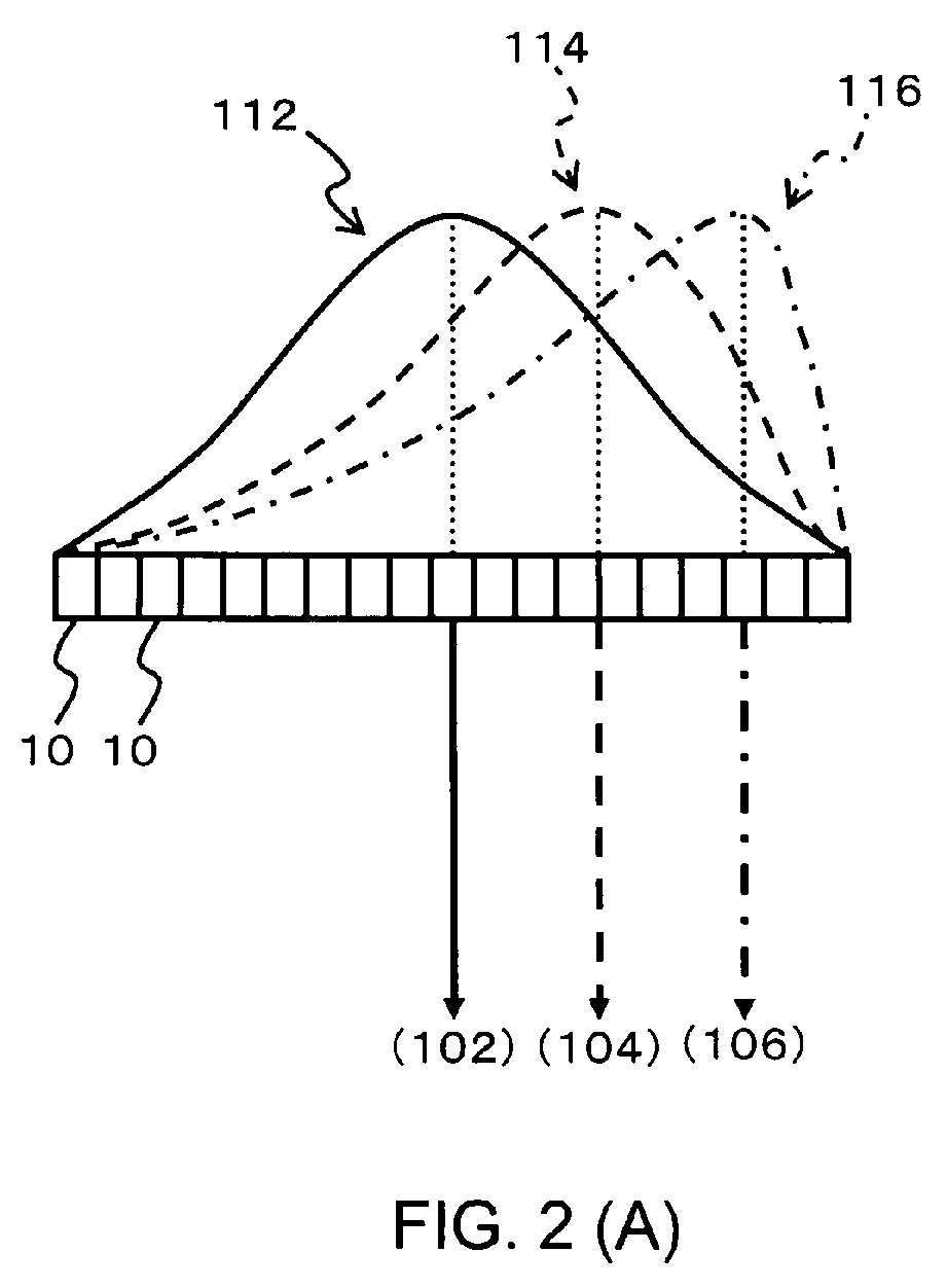
- FIG. 2 is a diagram for explaining the weighting process in the present embodiment.
- FIG. 2 (A) is a conceptual diagram showing an array transducer having the plurality of transducer elements 10, weighting functions 112, 114, and 116 indicating the magnitudes of the receptions weights for the transducer elements 10, and reception beams 102, 104, and 106 which are electrically scanned and are moved.
- the weighting functions 112, 114, 1nad 116 shown in FIG. 2 (A) are Beta density functions.
- x represents a coordinate in the array (aperture) direction. That is, x represents a position, within the array, of the transducer element 10 arranged in the one-dimensional manner.
- x is normalized within a range of 0 - 1.
- a position of one end of the transducer elements 10 which are arranged in the one-dimensional manner corresponds to a value of 0 and the position of the other end corresponds to a value of 1.
- variable a represents a normalization coefficient for setting the maximum value of y(x) to 1
- variables b and c are parameters for controlling degree of skewness of y (x), direction of skew, and area of y(x).
- the reception beams 102, 104, and 106 are formed using all of the transducer elements 10 of the array transducer. In other words, all range of the array transducers is set as receive aperture. All of the transducer elements 10 are used, and, with the electrical scan control, reception beams 102, 104, and 106 at positions which differ from each other are formed.
- the reception beam 102 is formed using the weighting function 112.
- the position of the peak of the weighting function 112, that is, the position of the transducer element 10 having the maximum weight is at the position of the reception beam 102.
- the reception beam 104 is formed using the weighting function 114, and the position of the peak of the weighting function 114 is at the position of the reception beam 104.
- the reception beam 106 is formed using the weighting function 116, and the position of the peak of the weighting function 116 is at the position of the reception beam 106.
- the positions of the peaks of the weighing functions 112, 114, and 116 are shifted in the receive aperture to follow the movement of the reception beams 102, 104, and 106 by the electrical scan.
- the sensitivity is improved and the grating lobe is reduced compared to, for example, a case in which the position of the peak of the reception weights is significantly deviated from the position of the reception beam.
- the areas of the functions of the weighting functions 112, 114, and 116 are desirably equal to each other.
- FIG. 2(B) shows a conceptual diagram of an array transducer having the plurality of transducer elements 10, weighting functions 122, 124, and 126 indicating the magnitudes of the reception weights for the transducer elements 10, and reception beams 102, 104, and 106 which are electrically scanned and are moved.
- the weighting functions 122, 124, and 126 shown in FIG. 2(B) are triangular functions, and the reception beam 102 is formed using the weighting function 122.
- the position of the peak of the weighting function 122 that is, the position of the transducer element 10 having the maximum weight is at the position of the reception beam 102.
- the reception beam 104 is formed using the weighting function 124, and the position of the peak of the weighting function 124 is at the position of the reception beam 104.
- the reception beam 106 is formed using the weighting function 126, and the position of the peak of the weighting function 126 is at the position of the reception beam 106.
- a restriction area is provided at the end of the array transducer, and the position of the peak of the reception weights is fixed within the restriction area, to inhibit the skewness of the weighting function to become significantly great.
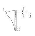
- FIG. 3 is a diagram for explaining the reception weighting process in the restriction area.
- FIG. 3 shows a conceptual diagram of an array transducer having the plurality of transducer elements 10, a weighting function 116 indicating the magnitudes of the reception weights for the transducer elements 10, and the reception beams 106 and 108 which are electrically scanned and are moved.
- the restriction area is provided at an end of the array transducer.
- the area of 0 - 0.2 on one end and the area of 0.8 - 1.0 on the other end are set as the restriction area.
- the area other than the restriction area for example, the area of 0.2 ⁇ 0.8 of the normalized coordinate is set as a following area.
- the reception beam 106 is formed at a boundary position between the following area and the restriction area.
- the reception beam 106 is formed at the position of 0.8 in the normalized coordinate.
- the position of the peak of the reception weights is shifted in the receive aperture to follow the movement of the reception beam (refer to FIG. 2 ). Because of this, the position of the peak of the weighting function 116 corresponding to the reception beam 106 matches the position of the reception beam 106.
- the position of the peak of the reception weights is fixed regardless of the movement of the reception beam.
- the weighting function 116 having the position of the peak fixed is used, and the reception beam 108 is formed using the weighting function 116.
- the weighting function at the position of 0.2 is used.
- the position of the peak of the reception weights is shifted in the following area.
- the size of the receive aperture may be changed according to the depth along a depth direction of the reception beam.
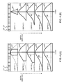
- FIG. 4 is a diagram for explaining the control of the receive aperture according to the depth.
- FIG. 4 (A) shows an array transducer having the plurality of transducer elements 10 and reception beam 104 formed by the array transducer.
- FIG. 4 (A) shows a conceptual diagram of the reception weights corresponding to the depths. For example, a weighting function W1 is used in depth 1, and a weighting function W2 is used in depth 2.
- the weighting functions W1 ⁇ W5 in the depth 1 through depth 5 in FIG. 4(A) are formed on the basis of the weighting function W4 at the depth 4.
- the weighting function W4 at the depth 4 has, for example, the same shape as the weighting function 114 shown in FIG. 2(A) .
- the receive aperture is narrowed to a region near the reception beam 104.
- the function portion corresponding to the aperture portion at the depth 1 is cut out from the weighting function W4, to form the weighting function W1.
- the receive aperture is widened compared to the case of the depth 1.
- the function portion corresponding to the aperture portion at the depth 2 is cut out from the weighting function W4, to form the weighting function W2.
- the function portion corresponding to the aperture portion at the depth 3 is cut out from the weighting function W4, to form the weighting function W3.
- the receive aperture is widened to the entire region of the array transducer, and the weighting function W4 corresponding to the entire region of the array transducer is used.
- the weighting function W4 is uniformly raised over the entire region of the array transducer, to form the weighting function W5.
- the weighting function W5 may be used or a function may be used in which the weighting function W5 is raised according to the depth.
- the size of the receive aperture is changed according to the depth, from the depth 1 to the depth 4.
- the positions of the peaks of the weighting functions W1 ⁇ W5 match the position of the reception beam 104 at each depth.
- the center position M of the receive aperture and the position of the reception beam 104 deviate from each other
- FIG. 4 (B) shows a conceptual diagram of the reception weights depending on the depths.
- the weighting function W1 is used at the depth 1
- the weighting function W2 is used at the depth 2.
- the width of the function is changed according to the size of the receive aperture.
- the weighting function W4 at the depth 4 has the same shape as the weighting function 114 shown in FIG. 2(A) , for example.
- the receive aperture is narrowed to only a region near the reception beam 104 at the depth 1.
- the weighting function W1 having a width corresponding to the aperture portion at the depth 1 is formed.
- the receive aperture is gradually widened, and the width of the function is gradually widened correspondingly, for weighting functions W1 ⁇ W4.
- the weighting function W4 is uniformly raised over the entire region of the array transducer, to form the weighting function W5.
- the weighting function W5 may be used or a function in which the weighting function W5 is raised according to the depth may be used.
- FIG. 4(B) at the depth 1 and the depth 2, weighting functions W1 and W2 symmetric to the left and right are used, and, at the depths 3 through depth 5, the center position M of the receive aperture and the position of the reception beam 104 deviate from each other.
- control of the size of the receive aperture according to the depth may also be applied to, for example, a reception dynamic focus control.
Landscapes
- Health & Medical Sciences (AREA)
- Engineering & Computer Science (AREA)
- Life Sciences & Earth Sciences (AREA)
- Physics & Mathematics (AREA)
- Biomedical Technology (AREA)
- Heart & Thoracic Surgery (AREA)
- Radar, Positioning & Navigation (AREA)
- General Physics & Mathematics (AREA)
- Biophysics (AREA)
- Nuclear Medicine, Radiotherapy & Molecular Imaging (AREA)
- Pathology (AREA)
- Radiology & Medical Imaging (AREA)
- Computer Networks & Wireless Communication (AREA)
- Remote Sensing (AREA)
- Medical Informatics (AREA)
- Molecular Biology (AREA)
- Surgery (AREA)
- Animal Behavior & Ethology (AREA)
- General Health & Medical Sciences (AREA)
- Public Health (AREA)
- Veterinary Medicine (AREA)
- Ultra Sonic Daignosis Equipment (AREA)
- Measurement Of Velocity Or Position Using Acoustic Or Ultrasonic Waves (AREA)
- Investigating Or Analyzing Materials By The Use Of Ultrasonic Waves (AREA)
Abstract
Description
- The present invention relates to an ultrasound diagnosis apparatus, and in particular to processing of a received signal.
- Anarray-typeultrasoundtransducer (array transducer) having an array of transducer elements comprising a plurality of transducer elements is known. In addition, in order to reduce side lobes of ultrasound beam during transmission and reception of the ultrasound using the array transducer, a technique is known in which weights are assigned according to positions of the transducer elements in a transmit aperture or a receive aperture.
- For example,
JP Hei 7-116163 A Patent Document 1, a position of a peak of the reception weights and the position of the center of the receive aperture are matched regardless of the position of the ultrasound beam (refer to FIG. 9 of Patent Document 1). -
JP2005-253699A JP2008-43531A Patent Document 2 discloses that, when the ultrasound beam direction is steered in a slanted direction, a gain difference is caused in signals in the transducer elements according to the change of the path of the ultrasound, and that, in order to correct this gain difference, weights which are not symmetrical (asymmetrical weights) are used.Patent Document 3 discloses a technique to inhibit temperature increase in the probe by alternately switching between asymmetrical weights. - When the distribution of the weights is set symmetrical and the position of the peak of the reception weights and the position of the center of the receive aperture are matched regardless of the position of the ultrasound beam, if the position of the peak of the reception weights is significantly deviated from the position of the ultrasound beam, problems may be caused such as reduction of sensitivity and increase in grating lobe. Such problems cannot be solved by simply setting the distribution of the weights to be asymmetrical.
- Under the above-described circumstances, the present inventors have researched and developed weights for the array transducer.
- The present invention was conceived in view of the above-described circumstances, and an advantage of the present invention is that an improved technique is provided for weighting of signals received by the array transducer.
- In order to achieve at least the advantage described above, according to one aspect of the present invention, there is provided an ultrasound diagnosis apparatus comprising an array transducer having a plurality of transducer elements, a transmitting unit which outputs a transmission signal to the plurality of transducer elements, and a receiving unit which applies a reception weight on a reception signal obtained from the plurality of transducer elements in a receive aperture, based on a position of each transducer element in the receive aperture, wherein the receiving unit shifts a position of a peak of the reception weights in the receive aperture, to follow a movement of the reception beam.
- With the structure of the above-described aspect of the present invention, because the position of the peak of the reception weights is shifted in the receive aperture to follow the movement of the reception beam, advantages such as improvement of the reception sensitivity and reduction of the grating lobe can be obtained compared to a case, for example, in which the position of the peak of the reception weights is fixed at the center of the receive aperture.
- According to various aspects of the present invention, an improved technique for reception weights of the array transducer is provided. For example, according to preferred configurations of the present invention, because the position of the peak of the reception weights is shifted in the receive aperture to follow the movement of the reception beam, advantages such as improvement of the reception sensitivity and reduction of the grating lobe can be obtained compared to a case, for example, in which the position of the peak of the reception weights is fixed at the center of the receive aperture.
- An exemplary embodiment of the present invention will be described in detail based on the following figures, wherein:
-
FIG. 1 is a functional block diagram showing an overall structure of an ultrasound diagnosis apparatus according to a preferred embodiment of the present invention; -
FIG. 2 is a diagram for explaining a weighting process in a preferred embodiment of the present invention; -
FIG. 3 is a diagram for explaining a reception weighting process in a restriction area; and -
FIG. 4 is a diagram for explaining control of the receive aperture according to a depth. - A preferred embodiment of the present invention will now be described.
-
FIG. 1 shows an ultrasound diagnosis apparatus according to a preferred embodiment of the present invention, and is a functional block diagram showing an overall structure of the ultrasound diagnosis apparatus. - An ultrasound diagnosis apparatus shown in
FIG. 1 comprises an array transducer having a plurality oftransducer elements 10. The plurality oftransducer elements 10 are arranged in a one-dimensional manner. In the present embodiment, for example, a linear-type probe or a convex-type probe is formed by the plurality of thetransducer elements 10. - The plurality of
transducer elements 10 vibrate according to a transmission signal which is output from a transmittingunit 90, and transmit an ultrasound to, for example, a living body. The transmittingunit 90 supplies a transmission signal to each of the plurality oftransducer elements 10. In this process, adelayprocess or the like is applied to the transmission signal according to thetransducer elements 10, to form an ultrasound transmission beam. The transmission beam formation is thus realized, and the ultrasound transmission beam is electrically scanned. Thetransducer element 10 outputs a reception signal obtained as a result of transmitting the ultrasound. - A
delay circuit 20 and aweighting circuit 30 are correlated to each of the plurality oftransducer elements 10. Thedelay circuit 20 is a circuit which applies a delaying process to the reception signal obtained from thecorresponding transducer element 10. The plurality ofdelay circuits 20 are controlled by adelay controller 70. With thedelay circuit 20, the delaying process for forming the ultrasound reception beam is applied to the reception signal obtained from thecorresponding transducer element 10. - The
weighting circuit 30 is a circuit which applies a weighting process according to thecorresponding transducer element 10. That is, theweighting circuit 30 applies a weighting process of a voltage (amplitude) on the reception signal for which the delaying process is applied in thecorresponding delay circuit 20. The weighting process is executed based on control by aweight controller 80. In the present embodiment, the weighting process is executed to obtain advantages such as, for example, improvement of reception sensitivity and reduction of grating lobe. The weighting process in the present embodiment will be described later in more detail. - A reception
beam forming unit 40 forms an ultrasound reception beam based on a reception signal which is output from the plurality ofweighting circuits 30. The receptionbeam forming unit 40 applies, for example, an adding process on the plurality of reception signals to which the delaying process and the weighting process are applied, to realize reception beam formation. A reception beam corresponding to the transmission beam is thus formed and the ultrasound beam (the transmission beam and the reception beam) is electrically scanned. - A
signal processor 50 applies a signal process such as detection and logarithmic compression on the reception signal after the phase adding process is applied. Alternatively, an extraction process of Doppler information or the like may be executed in thesignal processor 50. The signal processed by thesignal processor 50 is supplied to animage forming unit 60. Theimage forming unit 60 applies a coordinate conversion or an interpolation process on the input signal, and forms a B-mode image or the like. Alternatively, a Doppler waveform or a color Doppler image may be formed based on the Doppler information. An image formed in theimage forming unit 60 in this manner is displayed on adisplay unit 62. - The overall structure of the present embodiment has been described. Next, a weighting process in the present embodiment will be described in detail. In the following description, for portions (structures) shown in
FIG. 1 , the reference numerals ofFIG. 1 will be used. - In the present embodiment, a reception weight is applied to the reception signal obtained from the plurality of
transducer elements 10 in the receive aperture, according to the position of thetransducer element 10 in the receive aperture. In addition, a position of a peak of the reception weights is shifted in the receive aperture to follow the movement of the reception beam. It is preferable that the magnitude of the reception weight be gradually decreased from the position of the peak of the reception weights toward the ends of the receive aperture. -
FIG. 2 is a diagram for explaining the weighting process in the present embodiment.FIG. 2 (A) is a conceptual diagram showing an array transducer having the plurality oftransducer elements 10,weighting functions transducer elements 10, andreception beams weighting functions 112, 114,1nad 116 shown inFIG. 2 (A) are Beta density functions. The Beta density function y(x) is represented as follows:
- In
Equation 1, x represents a coordinate in the array (aperture) direction. That is, x represents a position, within the array, of thetransducer element 10 arranged in the one-dimensional manner. InEquation 1, x is normalized within a range of 0 - 1. In other words, a position of one end of thetransducer elements 10 which are arranged in the one-dimensional manner corresponds to a value of 0 and the position of the other end corresponds to a value of 1. InEquation 1, variable a represents a normalization coefficient for setting the maximum value of y(x) to 1, and variables b and c are parameters for controlling degree of skewness of y (x), direction of skew, and area of y(x). - In
FIG. 2 (A) , the reception beams 102, 104, and 106 are formed using all of thetransducer elements 10 of the array transducer. In other words, all range of the array transducers is set as receive aperture. All of thetransducer elements 10 are used, and, with the electrical scan control, reception beams 102, 104, and 106 at positions which differ from each other are formed. - The
reception beam 102 is formed using theweighting function 112. The position of the peak of theweighting function 112, that is, the position of thetransducer element 10 having the maximum weight is at the position of thereception beam 102. Similarly, thereception beam 104 is formed using the weighting function 114, and the position of the peak of the weighting function 114 is at the position of thereception beam 104. Finally, thereception beam 106 is formed using theweighting function 116, and the position of the peak of theweighting function 116 is at the position of thereception beam 106. - As shown in
FIG. 2(A) , in the present embodiment, the positions of the peaks of the weighingfunctions - In order to not vary the reception sensitivity according to the position of the reception beam, it is desirable to shift the position of the peak of the reception weights while maintaining a total sum of the reception weights at a constant. For example, the areas of the functions of the weighting functions 112, 114, and 116 are desirably equal to each other.
- Alternatively, for the reception weighting function, a triangular function as shown in
FIG. 2(B) may be used.FIG. 2 (B) shows a conceptual diagram of an array transducer having the plurality oftransducer elements 10, weighting functions 122, 124, and 126 indicating the magnitudes of the reception weights for thetransducer elements 10, andreception beams - The weighting functions 122, 124, and 126 shown in
FIG. 2(B) are triangular functions, and thereception beam 102 is formed using theweighting function 122. The position of the peak of theweighting function 122, that is, the position of thetransducer element 10 having the maximum weight is at the position of thereception beam 102. Similarly, thereception beam 104 is formed using theweighting function 124, and the position of the peak of theweighting function 124 is at the position of thereception beam 104. Finally, thereception beam 106 is formed using theweighting function 126, and the position of the peak of theweighting function 126 is at the position of thereception beam 106. - As shown in
FIG. 2 , as the position of the reception beam comes closer to the end of the receive aperture, the skewness of the weighting function gradually increases. When the skewness of the weighting function is significantly large, the reduction advantage of the side lobe is weakened. Therefore, in the present embodiment, a restriction area is provided at the end of the array transducer, and the position of the peak of the reception weights is fixed within the restriction area, to inhibit the skewness of the weighting function to become significantly great. -
FIG. 3 is a diagram for explaining the reception weighting process in the restriction area.FIG. 3 shows a conceptual diagram of an array transducer having the plurality oftransducer elements 10, aweighting function 116 indicating the magnitudes of the reception weights for thetransducer elements 10, and the reception beams 106 and 108 which are electrically scanned and are moved. - The restriction area is provided at an end of the array transducer. For example, in a normalized coordinate in which the position of one end of the array transducer having the plurality of
transducer elements 10 arranged in the one-dimensional manner is set as 0 and the position of the other end is set as 1, the area of 0 - 0.2 on one end and the area of 0.8 - 1.0 on the other end are set as the restriction area. The area other than the restriction area, for example, the area of 0.2 ∼ 0.8 of the normalized coordinate is set as a following area. - In
FIG. 3 , thereception beam 106 is formed at a boundary position between the following area and the restriction area. In other words, thereception beam 106 is formed at the position of 0.8 in the normalized coordinate. In the following area of the normalized coordinate of 0.2 - 0.8, the position of the peak of the reception weights is shifted in the receive aperture to follow the movement of the reception beam (refer toFIG. 2 ). Because of this, the position of the peak of theweighting function 116 corresponding to thereception beam 106 matches the position of thereception beam 106. - In the restriction area, on the other hand, the position of the peak of the reception weights is fixed regardless of the movement of the reception beam. For example, in the restriction area of the normalized coordinate of 0.8 - 1, the
weighting function 116 having the position of the peak fixed is used, and thereception beam 108 is formed using theweighting function 116. In the restriction area of normalized coordinate of 0 - 0.2, the weighting function at the position of 0.2 is used. - As described above, in the present embodiment, the position of the peak of the reception weights is shifted in the following area. In addition, the size of the receive aperture may be changed according to the depth along a depth direction of the reception beam.
-
FIG. 4 is a diagram for explaining the control of the receive aperture according to the depth.FIG. 4 (A) shows an array transducer having the plurality oftransducer elements 10 andreception beam 104 formed by the array transducer. In addition,FIG. 4 (A) shows a conceptual diagram of the reception weights corresponding to the depths. For example, a weighting function W1 is used indepth 1, and a weighting function W2 is used indepth 2. - The weighting functions W1 ∼ W5 in the
depth 1 throughdepth 5 inFIG. 4(A) are formed on the basis of the weighting function W4 at thedepth 4. The weighting function W4 at thedepth 4 has, for example, the same shape as the weighting function 114 shown inFIG. 2(A) . - At the
depth 1 which is the shallowest position inFIG. 4(A) , the receive aperture is narrowed to a region near thereception beam 104. The function portion corresponding to the aperture portion at thedepth 1 is cut out from the weighting function W4, to form the weighting function W1. - At the
depth 2, which is deeper than thedepth 1, the receive aperture is widened compared to the case of thedepth 1. The function portion corresponding to the aperture portion at thedepth 2 is cut out from the weighting function W4, to form the weighting function W2. At thedepth 3, which is deeper than both thedepth 1 and thedepth 2, the function portion corresponding to the aperture portion at thedepth 3 is cut out from the weighting function W4, to form the weighting function W3. - At the
depth 4, which is still deeper than thedepth 3, the receive aperture is widened to the entire region of the array transducer, and the weighting function W4 corresponding to the entire region of the array transducer is used. At thedepth 5, which is deeper than thedepth 4, the weighting function W4 is uniformly raised over the entire region of the array transducer, to form the weighting function W5. At depths deeper than thedepth 5, the weighting function W5 may be used or a function may be used in which the weighting function W5 is raised according to the depth. - In
FIG. 4(A) , the size of the receive aperture is changed according to the depth, from thedepth 1 to thedepth 4. By narrowing the receive aperture to a region near thereception beam 104 at relatively shallow positions such as thedepth 1 through thedepth 3, it is possible to reduce the grating lobe. InFIG. 4(A) also, the positions of the peaks of the weighting functions W1 ∼ W5 match the position of thereception beam 104 at each depth. At depths from thedepth 3 to thedepth 5, the center position M of the receive aperture and the position of thereception beam 104 deviate from each other - In changing the receive aperture according to the depth, it is possible to change the width of the weighting function according to the size of the receive aperture, as shown in
FIG. 4(B). FIG. 4 (B) shows a conceptual diagram of the reception weights depending on the depths. For example, the weighting function W1 is used at thedepth 1, and the weighting function W2 is used at thedepth 2. - In the weighting functions W1 ∼ W5 at
depths 1 throughdepth 5 inFIG. 4(B) , the width of the function is changed according to the size of the receive aperture. The weighting function W4 at thedepth 4 has the same shape as the weighting function 114 shown inFIG. 2(A) , for example. - In
FIG. 4(B) , the receive aperture is narrowed to only a region near thereception beam 104 at thedepth 1. The weighting function W1 having a width corresponding to the aperture portion at thedepth 1 is formed. As the depth is increased from thedepth 1 to thedepth 4, the receive aperture is gradually widened, and the width of the function is gradually widened correspondingly, for weighting functions W1 ∼ W4. - At the
depth 5, the weighting function W4 is uniformly raised over the entire region of the array transducer, to form the weighting function W5. At depths deeper than thedepth 5, the weighting function W5 may be used or a function in which the weighting function W5 is raised according to the depth may be used. InFIG. 4(B) , at thedepth 1 and thedepth 2, weighting functions W1 and W2 symmetric to the left and right are used, and, at thedepths 3 throughdepth 5, the center position M of the receive aperture and the position of thereception beam 104 deviate from each other. - The above-described control of the size of the receive aperture according to the depth may also be applied to, for example, a reception dynamic focus control.
- A preferred embodiment of the present invention has been described. The above-described preferred embodiment, however, is merely exemplary, and does not limit the scope of the present invention.
Claims (15)
- An ultrasound diagnosis apparatus comprising:an array transducer having a plurality of transducer elements;a transmitting unit which outputs a transmission signal to the plurality of transducer elements; anda receiving unit which applies a reception weight on a reception signal obtained from the plurality of transducer elements in a receive aperture, based on a position of each transducer element in the receive aperture, whereinthe receiving unit shifts a position of a peak of the reception weights in the receive aperture, to follow a movement of the reception beam.
- The ultrasound diagnosis apparatus according to Claim 1, wherein
the receiving unit sets forms of the following to differ from each other between a restriction area having the plurality of transducer elements placed at an end of the array transducer or at ends of the array transducer and a following area having the plurality of transducer elements other than the plurality of transducer elements placed at the end of the array transducer. - The ultrasound diagnosis apparatus according to Claim 2, wherein
the receiving unit causes the position of the peak of the reception weights to follow such that the position of the peak matches the position of the reception beam in the following area. - The ultrasound diagnosis apparatus according to Claim 2, wherein
the receiving unit fixes the position of the peak of the reception weights in the restriction area. - The ultrasound diagnosis apparatus according to Claim 2, wherein
the receiving unit causes the position of the peak of the reception weights to follow such that the position of the peak matches the position of the reception beam in the following area and fixes the position of the peak of the reception weights in the restriction area. - The ultrasound diagnosis apparatus according to Claim 1, wherein
the receiving unit shifts the position of the peak of the reception weights while maintaining a constant value for the total sum of the reception weights in the receive aperture. - The ultrasound diagnosis apparatus according to Claim 6, wherein
the receiving unit applies the reception weight based on a Beta density function or a triangular function. - The ultrasound diagnosis apparatus according to Claim 5, wherein
the receiving unit shifts the position of the peak of the reception weights while maintaining a constant value for the total sum of the reception weights in the receive aperture. - The ultrasound diagnosis apparatus according to Claim 8, wherein
the receiving unit applies the reception weight based on a Beta density function or a triangular function. - The ultrasound diagnosis apparatus according to Claim 1, wherein
the receiving unit changes a size of the receive aperture according to a depth along a depth direction of the reception beam. - The ultrasound diagnosis apparatus according to Claim 5, wherein
the receiving unit changes a size of the receive aperture according to a depth along a depth direction of the reception beam. - The ultrasound diagnosis apparatus according to Claim 6, wherein
the receiving unit changes a size of the receive aperture according to a depth along a depth direction of the reception beam. - The ultrasound diagnosis apparatus according to Claim 7, wherein
the receiving unit changes a size of the receive aperture according to a depth along a depth direction of the reception beam. - The ultrasound diagnosis apparatus according to Claim 8, wherein
the receiving unit changes a size of the receive aperture according to a depth along a depth direction of the reception beam. - The ultrasound diagnosis apparatus according to Claim 9, wherein
the receiving unit changes a size of the receive aperture according to a depth along a depth direction of the reception beam.
Applications Claiming Priority (1)
| Application Number | Priority Date | Filing Date | Title |
|---|---|---|---|
| JP2008310023A JP4717109B2 (en) | 2008-12-04 | 2008-12-04 | Ultrasonic diagnostic equipment |
Publications (1)
| Publication Number | Publication Date |
|---|---|
| EP2194398A1 true EP2194398A1 (en) | 2010-06-09 |
Family
ID=41819264
Family Applications (1)
| Application Number | Title | Priority Date | Filing Date |
|---|---|---|---|
| EP09014375A Withdrawn EP2194398A1 (en) | 2008-12-04 | 2009-11-17 | Ultrasound diagnosis apparatus |
Country Status (4)
| Country | Link |
|---|---|
| US (1) | US9599700B2 (en) |
| EP (1) | EP2194398A1 (en) |
| JP (1) | JP4717109B2 (en) |
| CN (1) | CN101803932B (en) |
Families Citing this family (4)
| Publication number | Priority date | Publication date | Assignee | Title |
|---|---|---|---|---|
| JP5869958B2 (en) * | 2012-05-25 | 2016-02-24 | 富士フイルム株式会社 | Ultrasonic signal processing apparatus and ultrasonic signal processing method |
| TWI549657B (en) * | 2013-08-30 | 2016-09-21 | Univ Chang Gung | Can be used to detect the middle ear water device |
| US11918420B2 (en) * | 2018-06-06 | 2024-03-05 | Insightec Ltd. | Reflection autofocusing |
| CN119033412B (en) * | 2023-05-25 | 2025-09-16 | 河南工业大学 | Ultrasonic imaging method based on received signal variation coefficient |
Citations (3)
| Publication number | Priority date | Publication date | Assignee | Title |
|---|---|---|---|---|
| US4691570A (en) | 1984-03-12 | 1987-09-08 | Dietrich Hassler | Method and apparatus for ultrasonically scanning a subject with an ultrasound head |
| US5817023A (en) | 1997-05-12 | 1998-10-06 | General Electrical Company | Ultrasound imaging system with dynamic window function generator |
| US6289231B1 (en) | 1997-03-17 | 2001-09-11 | Fujitsu Limited | Wave receiving apparatus and ultrasonic diagnostic apparatus |
Family Cites Families (10)
| Publication number | Priority date | Publication date | Assignee | Title |
|---|---|---|---|---|
| JP3474233B2 (en) | 1993-10-22 | 2003-12-08 | フクダ電子株式会社 | Ultrasound diagnostic equipment |
| US5685308A (en) * | 1994-08-05 | 1997-11-11 | Acuson Corporation | Method and apparatus for receive beamformer system |
| US6056693A (en) * | 1999-08-16 | 2000-05-02 | General Electric Company | Ultrasound imaging with synthetic transmit focusing |
| DE10248747B4 (en) * | 2001-10-20 | 2018-08-02 | ZONARE Medical Systems, Inc. (n.d.Ges.d. Staates Delaware) | Wide-ray picture |
| US6629929B1 (en) | 2002-11-08 | 2003-10-07 | Koninklijke Philips Electronics N.V. | Method and apparatus for automatically setting the transmit aperture and apodization of an ultrasound transducer array |
| JP2004283265A (en) * | 2003-03-20 | 2004-10-14 | Aloka Co Ltd | Ultrasonic diagnostic equipment |
| JP2005253699A (en) | 2004-03-12 | 2005-09-22 | Ge Medical Systems Global Technology Co Llc | Control method of ultrasonic probe and ultrasonic diagnostic apparatus |
| JP5016782B2 (en) * | 2004-06-08 | 2012-09-05 | 株式会社東芝 | Ultrasonic diagnostic equipment |
| US8317712B2 (en) * | 2006-05-12 | 2012-11-27 | Koninklijke Philips Electronics N.V. Eindhoven | Retrospective dynamic transmit focusing for spatial compounding |
| JP4782639B2 (en) * | 2006-08-16 | 2011-09-28 | 日立アロカメディカル株式会社 | Ultrasonic diagnostic equipment |
-
2008
- 2008-12-04 JP JP2008310023A patent/JP4717109B2/en active Active
-
2009
- 2009-11-17 EP EP09014375A patent/EP2194398A1/en not_active Withdrawn
- 2009-11-25 US US12/626,215 patent/US9599700B2/en active Active
- 2009-12-03 CN CN2009102119442A patent/CN101803932B/en active Active
Patent Citations (3)
| Publication number | Priority date | Publication date | Assignee | Title |
|---|---|---|---|---|
| US4691570A (en) | 1984-03-12 | 1987-09-08 | Dietrich Hassler | Method and apparatus for ultrasonically scanning a subject with an ultrasound head |
| US6289231B1 (en) | 1997-03-17 | 2001-09-11 | Fujitsu Limited | Wave receiving apparatus and ultrasonic diagnostic apparatus |
| US5817023A (en) | 1997-05-12 | 1998-10-06 | General Electrical Company | Ultrasound imaging system with dynamic window function generator |
Also Published As
| Publication number | Publication date |
|---|---|
| JP4717109B2 (en) | 2011-07-06 |
| CN101803932A (en) | 2010-08-18 |
| JP2010131191A (en) | 2010-06-17 |
| US9599700B2 (en) | 2017-03-21 |
| US20100145198A1 (en) | 2010-06-10 |
| CN101803932B (en) | 2013-05-01 |
Similar Documents
| Publication | Publication Date | Title |
|---|---|---|
| JP4242472B2 (en) | Ultrasonic transducer array and ultrasonic imaging system | |
| EP0442450B1 (en) | Variable origin - variable angle acoustic scanning method and apparatus | |
| US7066886B2 (en) | Ultrasound imaging system and method based on simultaneous multiple transmit-focusing using weighted orthogonal chirp signals | |
| US5902241A (en) | Large-aperture imaging using transducer array with adaptive element pitch control | |
| US6910380B2 (en) | Ultrasonic transmitting and receiving apparatus | |
| US7722541B2 (en) | Multiple receive beams for rapid acquisition | |
| JP5205110B2 (en) | Ultrasonic imaging device | |
| EP2929839B1 (en) | Ultrasonic probe and ultrasonic diagnostic apparatus | |
| KR100875203B1 (en) | Acquisition Method of Ultrasound | |
| EP2284566A1 (en) | Ultrasound diagnostic apparatus | |
| EP2194398A1 (en) | Ultrasound diagnosis apparatus | |
| US20180098750A1 (en) | Ultrasound transducer with variable pitch | |
| EP2638860B1 (en) | Beam-forming method, ultrasonic diagnosis device, program, and integrated circuit | |
| EP2944976B1 (en) | Beam forming apparatus, method for forming beams, ultrasonic imaging apparatus, and ultrasonic probe | |
| US5517995A (en) | 2D array for phase aberration correction | |
| JP4632517B2 (en) | Transmission / reception wave phasing method and ultrasonic diagnostic apparatus | |
| US20040193050A1 (en) | Ultrasonic transmitting and receiving apparatus | |
| JP4589542B2 (en) | Ultrasonic diagnostic equipment | |
| EP1654987A1 (en) | Ultrasonographic diagnostic equipment | |
| JP4241825B2 (en) | Ultrasonic diagnostic equipment | |
| Jeong et al. | Simultaneous multizone focusing method with orthogonal chirp signals | |
| EP4372412B1 (en) | Ultrasonography apparatus and ultrasound image generation method | |
| JP5901431B2 (en) | Ultrasonic diagnostic apparatus, sound speed derivation method, and program | |
| JP2024084518A (en) | Ultrasound diagnostic equipment | |
| US20150065880A1 (en) | Ultrasound diagnostic device, sound velocity derivation method and program |
Legal Events
| Date | Code | Title | Description |
|---|---|---|---|
| PUAI | Public reference made under article 153(3) epc to a published international application that has entered the european phase |
Free format text: ORIGINAL CODE: 0009012 |
|
| AK | Designated contracting states |
Kind code of ref document: A1 Designated state(s): AT BE BG CH CY CZ DE DK EE ES FI FR GB GR HR HU IE IS IT LI LT LU LV MC MK MT NL NO PL PT RO SE SI SK SM TR |
|
| AX | Request for extension of the european patent |
Extension state: AL BA RS |
|
| 17P | Request for examination filed |
Effective date: 20101207 |
|
| RAP1 | Party data changed (applicant data changed or rights of an application transferred) |
Owner name: HITACHI ALOKA MEDICAL, LTD. |
|
| 17Q | First examination report despatched |
Effective date: 20120426 |
|
| RAP1 | Party data changed (applicant data changed or rights of an application transferred) |
Owner name: HITACHI, LTD. |
|
| STAA | Information on the status of an ep patent application or granted ep patent |
Free format text: STATUS: EXAMINATION IS IN PROGRESS |
|
| STAA | Information on the status of an ep patent application or granted ep patent |
Free format text: STATUS: THE APPLICATION IS DEEMED TO BE WITHDRAWN |
|
| 18D | Application deemed to be withdrawn |
Effective date: 20180602 |