EP2194389A1 - Bushing diagnosis - Google Patents
Bushing diagnosis Download PDFInfo
- Publication number
- EP2194389A1 EP2194389A1 EP08170770A EP08170770A EP2194389A1 EP 2194389 A1 EP2194389 A1 EP 2194389A1 EP 08170770 A EP08170770 A EP 08170770A EP 08170770 A EP08170770 A EP 08170770A EP 2194389 A1 EP2194389 A1 EP 2194389A1
- Authority
- EP
- European Patent Office
- Prior art keywords
- pressure
- temperature
- measurements
- bushing
- theoretical
- Prior art date
- Legal status (The legal status is an assumption and is not a legal conclusion. Google has not performed a legal analysis and makes no representation as to the accuracy of the status listed.)
- Granted
Links
Images


Classifications
-
- H—ELECTRICITY
- H01—ELECTRIC ELEMENTS
- H01B—CABLES; CONDUCTORS; INSULATORS; SELECTION OF MATERIALS FOR THEIR CONDUCTIVE, INSULATING OR DIELECTRIC PROPERTIES
- H01B3/00—Insulators or insulating bodies characterised by the insulating materials; Selection of materials for their insulating or dielectric properties
- H01B3/18—Insulators or insulating bodies characterised by the insulating materials; Selection of materials for their insulating or dielectric properties mainly consisting of organic substances
- H01B3/20—Insulators or insulating bodies characterised by the insulating materials; Selection of materials for their insulating or dielectric properties mainly consisting of organic substances liquids, e.g. oils
-
- G—PHYSICS
- G05—CONTROLLING; REGULATING
- G05B—CONTROL OR REGULATING SYSTEMS IN GENERAL; FUNCTIONAL ELEMENTS OF SUCH SYSTEMS; MONITORING OR TESTING ARRANGEMENTS FOR SUCH SYSTEMS OR ELEMENTS
- G05B19/00—Program-control systems
- G05B19/02—Program-control systems electric
- G05B19/04—Program control other than numerical control, i.e. in sequence controllers or logic controllers
- G05B19/042—Program control other than numerical control, i.e. in sequence controllers or logic controllers using digital processors
- G05B19/0428—Safety, monitoring
-
- G—PHYSICS
- G01—MEASURING; TESTING
- G01R—MEASURING ELECTRIC VARIABLES; MEASURING MAGNETIC VARIABLES
- G01R31/00—Arrangements for testing electric properties; Arrangements for locating electric faults; Arrangements for electrical testing characterised by what is being tested not provided for elsewhere
- G01R31/12—Testing dielectric strength or breakdown voltage ; Testing or monitoring effectiveness or level of insulation, e.g. of a cable or of an apparatus, for example using partial discharge measurements; Electrostatic testing
-
- G—PHYSICS
- G01—MEASURING; TESTING
- G01R—MEASURING ELECTRIC VARIABLES; MEASURING MAGNETIC VARIABLES
- G01R31/00—Arrangements for testing electric properties; Arrangements for locating electric faults; Arrangements for electrical testing characterised by what is being tested not provided for elsewhere
- G01R31/50—Testing of electric apparatus, lines, cables or components for short-circuits, continuity, leakage current or incorrect line connections
- G01R31/62—Testing of transformers
-
- G—PHYSICS
- G05—CONTROLLING; REGULATING
- G05B—CONTROL OR REGULATING SYSTEMS IN GENERAL; FUNCTIONAL ELEMENTS OF SUCH SYSTEMS; MONITORING OR TESTING ARRANGEMENTS FOR SUCH SYSTEMS OR ELEMENTS
- G05B2219/00—Program-control systems
- G05B2219/20—Pc systems
- G05B2219/24—Pc safety
- G05B2219/24042—Signature analysis, compare recorded with current data, if error then alarm
Definitions
- the present invention relates to electrical apparatuses having sealed fluid based insulating systems, such as bushings for pieces of electrical high-voltage equipment, and more particularly to a method, device and computer program product for diagnosing the status of an electrical apparatus having a sealed fluid based insulating system.
- One type of electrical apparatus that has a sealed fluid based insulating system is an electrical property measuring and field controlling apparatus, which may be a bushing.
- Bushings may be provided for pieces of electrical high-voltage equipment and are known to carry current of high voltage through a zone of a different potential, which different potential is ground potential when the bushing is a transformer bushing. In order to avoid being a safety hazard, the bushing itself needs to be monitored regarding how well it is functioning.
- One way to perform this may be through opening the bushing and take samples of the fluid, for instance oil, which is used as an insulating medium inside the bushing.
- the temperature of this oil can then be measured and used for diagnosing the bushing.
- the amount of oil in the bushing may be changed and the oil may also become contaminated when opening the bushing. There is in this case also a risk that the bushing is not sealed properly after such taking of samples.
- US 2005/0223782 does for instance describe a transformer monitoring system.
- the current of the transformer and an ambient temperature are measured. These are used for determining an oil temperature of the transformer.
- the actual transformer oil temperature is then measured and compared with the determined oil temperature and an anomaly is determined if a temperature difference exceeds a threshold.
- the inner pressure of the transformer is determined and compared with a threshold and an anomaly is determined if this pressure exceeds a pressure threshold.
- US 2002/0161558 describes a transformer monitoring system. In the system a number of physical quantities are monitored, like current, top oil temperature and ambient temperature.
- US 4,654,806 describes a transformer monitoring system. In this system various parameters are measured, such as oil temperature, ambient temperature and pressure. These are then each compared with a corresponding threshold.
- EP 747 715 does for instance describe diagnosing the status of a bushing through measuring imbalance current waveforms from a number of bushings, comparing imbalance values with each other and initial values to determine if a threshold is exceeded. If the threshold is exceeded there is a determination being made about which of the bushings that have changed as well as the changes in capacitances and power values of these bushings. These changed capacitances and power values are then temperature compensated based on (transformer) top-oil and ambient temperatures. This document seems to require several bushings for performing diagnosing and furthermore only measures the current.
- the present invention is directed towards solving the problem of providing diagnosis that can be performed for a single electrical apparatus having a sealed fluid based insulating system without having to open this electrical apparatus.
- This problem is generally solved through determining a theoretical apparatus pressure based on received measurements of a current running through the apparatus, comparing received measurements of an actual apparatus pressure with the theoretical apparatus pressure and diagnosing the status of the apparatus based on the comparison.
- One object of the present invention is thus to provide a method for diagnosing the status of an electrical apparatus having a sealed fluid based insulating system, which can be performed for a single bushing without having to open this electrical apparatus.
- This object is according to the present invention solved through a method for diagnosing the status of an electrical apparatus having a sealed fluid based insulating system and comprising the steps of:
- Another object of the present invention is to provide a device for diagnosing the status of an electrical apparatus having a sealed fluid based insulating system, which can perform diagnosis for a single electrical apparatus without having to open this electrical apparatus.
- This object is according to another aspect of the present invention solved through a device for diagnosing the status of an electrical apparatus having a sealed fluid based insulating system comprising:
- a further object of the present invention is to provide a computer program product for diagnosing the status of an electrical apparatus having a sealed fluid based insulating system, which allows the diagnosis to be performed for a single electrical apparatus without having to open this electrical apparatus.
- This object is according to a further aspect of the present invention solved through a computer program product for diagnosing the status of an electrical apparatus having a sealed fluid based insulating system
- a computer program product for diagnosing the status of an electrical apparatus having a sealed fluid based insulating system
- computer program code provided on a data carrier for making a computer do, when said computer program code is loaded in the computer determine a corresponding theoretical apparatus pressure based on received measurements of a current running through the apparatus, receive measurements of an actual apparatus pressure, compare the actual apparatus pressure with the theoretical apparatus pressure, and diagnose the status of the apparatus based on the comparison.
- the present invention has a number of advantages. It allows diagnosing the status of a single electrical apparatus having a sealed fluid based insulating system without the electrical apparatus having to be opened for investigating the content of it. Such opening may negatively influence the comparison in that properties of insulating mediums used in the electrical apparatus may be changed, which may have a negative effect on the safety of the electrical apparatus. Also pollution and/or contaminants can enter the electrical apparatus. An opening may also lead to a re-closing not being performed properly. The electrical apparatus may become leaky. All these problems are avoided with the diagnosing of the present invention.
- the diagnosing can furthermore be performed in a very simple way with a limited number of further elements in addition to those that are normally used when diagnosing electrical apparatus and pieces of electrical high-voltage equipment, such as bushings and transformers.
- a bushing is one such apparatus that is used for measuring electrical properties of pieces electrical high-voltage equipment, which pieces of equipment may be conductors, power lines and inductively operating elements such as transformers and reactors.
- the present invention is directed towards providing such diagnosis. This type of diagnosis is provided for determining if the electrical apparatus is functioning properly or not and to determine in what way it is faulty if not functioning properly.
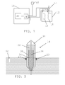
- Fig. 1 schematically shows a device 10 for diagnosing the functioning of an electrical apparatus having a sealed fluid based insulating system.
- This electrical apparatus is here a bushing 14.
- the device 10 includes at least one input and here only one input 24, which is connected to two surrounding temperature sensors, an ambient temperature sensor 22 and an insulating medium temperature sensor of a piece of electrical high-voltage equipment that the bushing is attached to.
- the piece of equipment is a transformer 12 provided in a transformer tank and the insulating medium is transformer oil in this tank.
- This transformer 12 has a first and a second winding 16 and 18.
- the insulating medium temperature sensor is therefore here a top oil temperature sensor 20.
- the input 24 is also connected to a current sensor 23 for detecting the current running through the bushing 14. It also has one connection to the bushing 14 for receiving apparatus pressure measurements. As an alternative to using one input for several types of measurements, it is of course possible to use several inputs for the various measurements.
- the bushing 14 is attached to the transformer 12 and more particularly to the second winding 18 of the transformer 12. In the figure there is no bushing connected to the first winding 16. It should be realized that it is of course possible that a bushing is connected also to this first winding 16 either instead of or in addition to the bushing 14 being connected to the second winding 18.
- the input 24 is finally connected to a diagnosing unit 26 provided in the interior of the device 10, which unit 26 performs diagnosis of the electrical apparatus, i.e. diagnoses the health and functioning of the bushing.
- the sensors may also include or be connected to A/D converters for providing digitalized measurements to the device 10.
- a sectional view of one bushing 14 being provided in the transformer at a distance from the top oil sensor 20 and that can be used with the present invention is schematically shown in fig. 2 .
- the bushing 14 As the bushing 14 is attached to the transformer a part of it is surrounded by the transformer oil of the transformer. The temperature of this transformer oil is determined by the top oil temperature sensor 20, which is placed in the transformer tank.
- the bushing 14 here includes a sealed chamber.
- the chamber has an extension in a direction, which direction is vertical when the bushing is attached to the transformer. In this chamber there runs a central electrical conductor 28 along this vertical direction, which conductor 28 is provided for connection to the transformer.
- the conductor 28 thus extends out of two opposite vertical ends of the chamber for being connected to the transformer at one end and may at the other end be connected to a line or to another electrical apparatus, where the end that is to be connected to the transformer is the lower vertical end.
- insulation 30 or a condenser core surrounding the conductor 28, which lower region is the part of the chamber that faces the transformer.
- the insulation 30 is typically made of paper and has a voltage control normally provided by foils that encircle the conductor 28 in this lower region.
- the paper may be cellulose or synthetic.
- the first fluid insulating medium is here furthermore a liquid insulating medium 32, which liquid insulating medium is here transformer oil, which may be a vegetable oil.
- This first insulating medium 32 is here filled in the chamber to a level so that all the insulation 30 is covered, i.e. the insulation 30 is here soaked in the first insulating medium 32.
- a second fluid insulating medium 34 which is here a gas, typically air. It may be another gas though, such as nitrogen.
- the second insulating medium 34 may here be provided at an overpressure.
- the second insulating medium 34 here provides a compressible volume for taking up volume variations of the liquid first insulating medium 32.
- the volume occupied by the second gaseous insulating medium 34 is therefore normally much smaller than the volume occupied by the first insulating medium 32.
- the second gaseous insulating medium 34 is for this reason also denoted a gas cushion.
- the first liquid insulating medium 32 is furthermore degassed.
- the first insulating medium is thus saturated and in a steady state.
- the current sensor 23 may include a current transformer that is provided in the transformer tank and encircling the bushing 14. This current transfer is then magnetically connected to the conductor 28. These two latter sensors are furthermore connected to the input of the diagnosing device in fig. 1 .
- A/D converters for converting analog measurement values into digital format.
- fig. 3 shows a flow chart of a number of method steps being performed in a method for diagnosing the status of a transformer bushing as shown in fig. 1 and 2 .
- the method starts with measuring the current in the conductor 28 of the bushing 14. These measurements are supplied from the bushing 14 to the input 24 of the diagnosing device 10, from where they are forwarded to the diagnosing unit 26. In this way the diagnosing unit 26 receives measurements of the current running through the bushing, step 38.
- the ambient temperature sensor 22 senses the ambient temperature, i.e. the temperature in the area surrounding the transformer 12 and bushing 14, and forwards ambient temperature measurements to the input 24 of the diagnosing device 10, from where they are forwarded to the diagnosing unit 26. Ambient temperature may for instance be room temperature of about 20°C.
- the transformer top oil temperature sensor 20 senses the top oil temperature of the oil, i.e.
- the diagnosing unit 26 also receives ambient temperature measurements and transformer top oil measurements, step 40. Based on this data, the diagnosing unit 26 then determines a theoretical bushing pressure.
- the theoretical bushing pressure is determined based on the current in the conductor 28.
- the amount and variation of the current over time in the conductor 28 gives rise to heat, which is transferred to the insulation 30 and first insulating medium 32.
- the heat transfer is dependent on known properties of the insulation 30 and the first insulating medium 32.
- the ambient temperature and the top oil temperature of the transformer 12 it is then possible to determine the temperature of the first insulating medium 32, which temperature is considered to be the bushing temperature.
- the bushing temperature is thus determined based on a determination of the heat generated in the bushing by the current, step 41, and the heat transferred to the surrounding media. This change in temperature is furthermore normally a slow process.
- This temperature furthermore gives rise to an expansion of this first insulating medium 32, which leads to the volume in the chamber being occupied by the first insulating medium increasing. Since the chamber is sealed, this expansion also leads to the volume of the second insulating medium decreasing.
- the temperature of the second insulating medium 34 or the gas cushion is here determined. This temperature depends on the previously determined bushing temperature, the ambient temperature and the current running through the conductor. Based on the gas cushion temperature and volume it is then possible to determine the pressure of the gas cushion. This pressure is then combined with the pressure of the first insulating medium in order to obtain a theoretical bushing pressure. In this way the diagnosing unit 26 thus determines a theoretical pressure of the bushing, step 42. It is thus clear that the theoretical pressure has a dependence of the bushing temperature.
- the theoretical pressure may be determined based on a model of the change in pressure in the gas cushion and through that the bushing pressure in relation to bushing temperature.
- this change in pressure is determined based on the change in volume of the first insulating medium, which change in volume indirectly influences the theoretical pressure, since it causes a change in volume of the second insulating medium, which then influences the theoretical pressure.
- ⁇ x is the density of this medium. This density has a constant component ⁇ a and a temperature dependent component ⁇ b
- T x is the average first insulating temperature in the bushing. This temperature T x is calculated from the heat transfer to the surrounding media and the heat generated in the bushing due to thermal and dielectric losses.
- the pressure sensor 36 detects the actual pressure in the bushing 14.
- the actual pressure is thus detected simultaneously with the measuring of the above-mentioned current.
- Measurements of the actual pressure are supplied from the pressure sensor 36 to the input 24 of the diagnosing device 10, from which input they are then forwarded to the diagnosing unit 26.
- the diagnosing unit 26 thus receives measurements of the corresponding actual pressure in the bushing, step 44.
- the detected actual pressure thus corresponds to the determined theoretical pressure and vice versa.
- the pressure measurements are furthermore correlated with the current measurements.
- step 46 which range can vary depending on the determined bushing temperature
- the diagnosing unit diagnoses or determines that the bushing is functioning satisfactorily, i.e. that the status of the bushing 14 is ok, step 48.
- the diagnosing unit 26 diagnoses that the bushing has changed its original properties or is faulty. In some variations of the present invention, this may be all that is done in the diagnosing of the bushing. The diagnosing may thus only involve separating a faulty from a functioning bushing based on the comparison of actual and theoretical pressures. In a preferred embodiment of the present invention, the diagnosing unit 26 however continues when having determined that a bushing has changed its original properties or is faulty and further diagnoses the status of the bushing based on comparing the way the actual pressure varies with bushing temperature with the way a set of reference pressure curves vary with temperature, step 50.
- fig. 4 shows a diagram of pressure in relation to temperature including a first curve 54 representing the theoretical pressure and a set of reference curves 56 - 64 representing various potential problems for the bushing.
- the X-axis shows the temperature in °C
- the Y-axis shows the pressure in kPa.
- These exemplifying curves are furthermore provided for a first insulating medium volume of 100 dm 3 and a second insulating medium volume of 15 dm 3 at room temperature.
- the curves, except for one potential problem curve, furthermore here represent a simplified situation where the second insulating medium has not started to enter or be solved in or mixed with the first insulating medium.
- a curve 54 (shown as a solid line) of the theoretical pressure or how the pressure should vary in relation to temperature when the bushing is functioning normally. This curve thus represents a bushing that functions satisfactory.
- a first potential problem curve 56 (shown as a first dashed line) of how the pressure varies with temperature for a bushing including too much insulating medium, i.e. too much transformer oil.
- a second potential problem curve 58 (shown as a first dash-dotted line) for a bushing including too little insulating medium, i.e. too little transformer oil.
- third potential problem curve 60 shows how the pressure varies with temperature for a bushing where an oil sample has been taken at high temperature.
- fourth potential problem curve 62 shows how the pressure varies with temperature for a leaking bushing, i.e. a bushing which is not completely tight.
- fifth potential problem curve 64 shows how the bushing pressure varies with temperature for a bushing where gas has been formed in the oil or where there has been overheating. This last potential problem curve does therefore represent a situation where the second insulating medium has entered, been solved in or mixed with the first insulating medium.
- the pressure in the bushing 14 may vary in relation to temperature in different ways because of various types of errors. It may for instance vary in one way if there is too much oil in the chamber of the bushing 14 and vary in another way if there is too little oil in the bushing 14.
- these two potential problem curves 56 and 58 like the theoretical pressure curve 54, have the same pressure in one point, which point is here a pressure of 100 kPa at room temperature, but otherwise differ from each other and also have different slopes.
- the pressure variations are larger with too much oil as compared with too little oil.
- the third curve 60 and the fifth curve 64 essentially involve a shifting of the theoretical pressure curve 54 up or down along the Y-axis. This means that these potential problems can be determined through investigating the size and sign of the difference between the measured and theoretical pressures for various temperatures when the measured pressure does not coincide with the theoretical pressure at room temperature. If the measured pressure is larger than the theoretical pressure by more than a third threshold value then gassing or overheating is determined, while if the measured pressure is lower than the theoretical pressure by more than a fourth threshold value, then a determination is made that an oil sample at high temperate has been taken. This means that if the oil sample has been taken via medium 34 the overpressure has been released at a high temperature. In the same way the third curve 60 may also represent an oil sample taken at a low pressure.
- the diagnosing unit 26 can therefore diagnose the status of the bushing through comparing the actual pressure variation with reference pressure variation curves, step 50, and indicate a potential problem that is associated with the reference pressure variation curve that the actual pressure variation is closest to, step 52. This means that if the measured pressure variation is closer to one such potential problem curve than to the theoretical pressure curve and the other reference pressure variation curves, the potential problem associated with this curve is chosen and indicated.
- the diagnosing according to the principles of the present invention can furthermore be performed in a very simple way with a limited number of additional elements.
- Surrounding temperature sensors (like top oil and ambient temperature sensors) and current sensors are well known and widely used in relation to bushings for performing monitoring of transformers.
- the additional elements needed are mainly a pressure sensor in a bushing as well as some additional processing power for performing the diagnosis.
- a monitoring function such as a bushing monitoring function, may be included as an additional function for a transformer monitoring function that is in many cases already present in relation a transformer.
- the diagnosing device may be provided as a computer where the input unit can be realized as a network interface such as a LAN interface and the diagnosing unit may be provided in the form of a processor with an associated program memory including computer program code that performs the diagnosing function of the invention when being run by the processor.
- the computer program code can then also be provided on a data carrier, such as memory stick or a CD ROM disc which code performs the diagnosing according to the present invention when the carrier is loaded into a computer.
- a data carrier such as memory stick or a CD ROM disc which code performs the diagnosing according to the present invention when the carrier is loaded into a computer.
- the present invention can be varied in many ways in addition to those already described.
- the bushing may be provided without insulation or condenser core.
- There may furthermore only be one insulating medium in the bushing, which may then be a gas, such as for instance SF6 or nitrogen.
- a gas such as for instance SF6 or nitrogen.
- the raised temperature of this medium that is the bushing temperature and also the bushing pressure used is the pressure of this medium.
- the model of the change in pressure that is used is then not depending on any change in volume, but only on the change in bushing temperature.
- the pressure sensor may furthermore have an alternative placing in that it is placed at the top of the chamber where the gas cushion is provided. If this placing is combined with a liquid first insulating medium and a second gaseous insulating medium it is possible that the theoretical and actual bushing pressures used are only based on the pressures of the second insulating medium.
- the described model of the theoretical pressure can of course be changed or adapted for taking account of gassing, i.e. that some of the second gaseous insulating medium does get mixed into the liquid first insulating medium.
- the pressure sensor of the bushing as well as the bushing may in some embodiments of the present invention be elements that are a part of the diagnosing device. Also one or both of the temperature sensors may be such elements. It may also be possible to determine the theoretical bushing pressure and bushing temperature without measuring ambient and transformer top oil temperatures.
- Diagnosing is not limited to inductively operating pieces of high-voltage equipment, like transformers and reactors, but can be used on any piece of high-voltage equipment that is sealed and has a thermally expandable insulation medium.
- the invention can furthermore be varied in that more than one bushing may be provided for a piece of equipment, like for instance three bushings, one for each phase of a power transmission system.
- more than one bushing may be provided for a piece of equipment, like for instance three bushings, one for each phase of a power transmission system.
- the bushing may furthermore not be directly connected to a piece of electrical equipment. It may first run through a wall and then be connected to the piece of equipment.
- the electrical apparatus is in fact not limited to bushings, but may be any electrical apparatus having a sealed fluid based insulating system and can therefore for instance also be a transformer or a reactor.
Landscapes
- Physics & Mathematics (AREA)
- General Physics & Mathematics (AREA)
- Engineering & Computer Science (AREA)
- Automation & Control Theory (AREA)
- Spectroscopy & Molecular Physics (AREA)
- Power Engineering (AREA)
- Chemical & Material Sciences (AREA)
- Oil, Petroleum & Natural Gas (AREA)
- Housings And Mounting Of Transformers (AREA)
- Testing Of Short-Circuits, Discontinuities, Leakage, Or Incorrect Line Connections (AREA)
- Testing Of Devices, Machine Parts, Or Other Structures Thereof (AREA)
- Measurement Of Radiation (AREA)
- Glass Compositions (AREA)
- Cable Accessories (AREA)
Abstract
Description
- The present invention relates to electrical apparatuses having sealed fluid based insulating systems, such as bushings for pieces of electrical high-voltage equipment, and more particularly to a method, device and computer program product for diagnosing the status of an electrical apparatus having a sealed fluid based insulating system.
- One type of electrical apparatus that has a sealed fluid based insulating system is an electrical property measuring and field controlling apparatus, which may be a bushing. Bushings may be provided for pieces of electrical high-voltage equipment and are known to carry current of high voltage through a zone of a different potential, which different potential is ground potential when the bushing is a transformer bushing. In order to avoid being a safety hazard, the bushing itself needs to be monitored regarding how well it is functioning.
- One way to perform this may be through opening the bushing and take samples of the fluid, for instance oil, which is used as an insulating medium inside the bushing. The temperature of this oil can then be measured and used for diagnosing the bushing. However, when this is done the properties of the bushing are altered. The amount of oil in the bushing may be changed and the oil may also become contaminated when opening the bushing. There is in this case also a risk that the bushing is not sealed properly after such taking of samples.
- There is therefore a need for an alternative way of diagnosing a bushing.
- There are in the art some documents describing diagnosing of transformers.
-
US 2005/0223782 does for instance describe a transformer monitoring system. Here the current of the transformer and an ambient temperature are measured. These are used for determining an oil temperature of the transformer. The actual transformer oil temperature is then measured and compared with the determined oil temperature and an anomaly is determined if a temperature difference exceeds a threshold. Also the inner pressure of the transformer is determined and compared with a threshold and an anomaly is determined if this pressure exceeds a pressure threshold. -
US 2002/0161558 describes a transformer monitoring system. In the system a number of physical quantities are monitored, like current, top oil temperature and ambient temperature. -
US 4,654,806 describes a transformer monitoring system. In this system various parameters are measured, such as oil temperature, ambient temperature and pressure. These are then each compared with a corresponding threshold. - All of these documents use monitoring of a transformer top oil temperature.
- There do also exist some documents related to diagnosing bushings.
-
EP 747 715 - The article "New Insulation Diagnostic and Monitoring Techniques for In-Service HV Apparatus" BY D.M. Allan, M.S. Blundell, K.J. Boyd and D.D. Hinde, Proceedings of the 3rd International Conference on Properties and Applications of Dielectric Materials, July 8 - 12, 1991, Tokyo, Japan describes a monitoring system for a transformer as well as for a transformer bushing through monitoring DDF (Dielectric Dissipation Factor).
- There is thus a need for a diagnosing of an electrical apparatus having a sealed fluid based insulating system that can be used without opening the electrical apparatus and taking samples and that may be applied for one single electrical apparatus.
- The present invention is directed towards solving the problem of providing diagnosis that can be performed for a single electrical apparatus having a sealed fluid based insulating system without having to open this electrical apparatus.
- This problem is generally solved through determining a theoretical apparatus pressure based on received measurements of a current running through the apparatus, comparing received measurements of an actual apparatus pressure with the theoretical apparatus pressure and diagnosing the status of the apparatus based on the comparison.
- One object of the present invention is thus to provide a method for diagnosing the status of an electrical apparatus having a sealed fluid based insulating system, which can be performed for a single bushing without having to open this electrical apparatus.
- This object is according to the present invention solved through a method for diagnosing the status of an electrical apparatus having a sealed fluid based insulating system and comprising the steps of:
- receiving measurements of a current running through the apparatus,
- determining a theoretical apparatus pressure based on the measured current,
- receiving measurements of a corresponding actual apparatus pressure,
- comparing the actual apparatus pressure with the theoretical apparatus pressure, and
- diagnosing the status of the apparatus based on the comparison.
- Another object of the present invention is to provide a device for diagnosing the status of an electrical apparatus having a sealed fluid based insulating system, which can perform diagnosis for a single electrical apparatus without having to open this electrical apparatus.
- This object is according to another aspect of the present invention solved through a device for diagnosing the status of an electrical apparatus having a sealed fluid based insulating system comprising:
- at least one input for receiving measurements of a current running through the apparatus and measurements of an actual apparatus pressure, and
- a diagnosing unit arranged to
determine a corresponding theoretical apparatus pressure based on the measured current,
compare the actual apparatus pressure with the theoretical apparatus pressure, and
diagnose the status of the apparatus based on the comparison. - A further object of the present invention is to provide a computer program product for diagnosing the status of an electrical apparatus having a sealed fluid based insulating system, which allows the diagnosis to be performed for a single electrical apparatus without having to open this electrical apparatus.
- This object is according to a further aspect of the present invention solved through a computer program product for diagnosing the status of an electrical apparatus having a sealed fluid based insulating system comprising
computer program code provided on a data carrier for making a computer do, when said computer program code is loaded in the computer
determine a corresponding theoretical apparatus pressure based on received measurements of a current running through the apparatus,
receive measurements of an actual apparatus pressure, compare the actual apparatus pressure with the theoretical apparatus pressure, and
diagnose the status of the apparatus based on the comparison. - The present invention has a number of advantages. It allows diagnosing the status of a single electrical apparatus having a sealed fluid based insulating system without the electrical apparatus having to be opened for investigating the content of it. Such opening may negatively influence the comparison in that properties of insulating mediums used in the electrical apparatus may be changed, which may have a negative effect on the safety of the electrical apparatus. Also pollution and/or contaminants can enter the electrical apparatus. An opening may also lead to a re-closing not being performed properly. The electrical apparatus may become leaky. All these problems are avoided with the diagnosing of the present invention. The diagnosing can furthermore be performed in a very simple way with a limited number of further elements in addition to those that are normally used when diagnosing electrical apparatus and pieces of electrical high-voltage equipment, such as bushings and transformers.
- Further objectives and advantages, as well as the structure and function of an exemplary embodiment will become apparent from a consideration of the description and drawings.
- The foregoing and other features and advantages of the invention will be apparent from the following, more particular description of an exemplary embodiment of the invention, as illustrated in the accompanying drawings wherein like reference numbers generally indicate identical, functionally similar, and/or structurally similar elements. In the drawings
-
fig. 1 shows a schematic view of a device according to the present invention being connected to a bushing as well as to temperature sensors, where the bushing is in turn attached to a transformer, -
fig. 2 shows a sectional view of the bushing; -
fig. 3 shows a flow chart of a number of method steps being performed in a method for diagnosing the status of a bushing, and -
fig. 4 shows a diagram with curves regarding pressure in relation to temperature and including a first curve representing a theoretical pressure and a set of reference curves representing potential problems for the bushing. - Embodiments of the invention are discussed in detail below. In describing embodiments, specific terminology is employed for the sake of clarity. However, the invention is not intended to be limited to the specific terminology so selected. While specific exemplary embodiments are discussed, it should be understood that this is done for illustration purposes only. A person skilled in the relevant art will recognize that other components and configurations can be used without parting from the spirit and scope of the invention.
- Electrical apparatuses having sealed fluid based insulating systems are known to be used in relation to high-voltage applications. A bushing is one such apparatus that is used for measuring electrical properties of pieces electrical high-voltage equipment, which pieces of equipment may be conductors, power lines and inductively operating elements such as transformers and reactors.
- In order to provide correct measurement results, which are vital for the control and safety in high-voltage applications, there is a need for the electrical apparatus to function properly. The functioning of it does therefore have to be diagnosed. The present invention is directed towards providing such diagnosis. This type of diagnosis is provided for determining if the electrical apparatus is functioning properly or not and to determine in what way it is faulty if not functioning properly.
-
Fig. 1 schematically shows adevice 10 for diagnosing the functioning of an electrical apparatus having a sealed fluid based insulating system. This electrical apparatus is here abushing 14. Thedevice 10 includes at least one input and here only oneinput 24, which is connected to two surrounding temperature sensors, anambient temperature sensor 22 and an insulating medium temperature sensor of a piece of electrical high-voltage equipment that the bushing is attached to. In the embodiment of the invention depicted infig. 1 , the piece of equipment is atransformer 12 provided in a transformer tank and the insulating medium is transformer oil in this tank. Thistransformer 12 has a first and a second winding 16 and 18. The insulating medium temperature sensor is therefore here a topoil temperature sensor 20. Theinput 24 is also connected to acurrent sensor 23 for detecting the current running through thebushing 14. It also has one connection to thebushing 14 for receiving apparatus pressure measurements. As an alternative to using one input for several types of measurements, it is of course possible to use several inputs for the various measurements. Thebushing 14 is attached to thetransformer 12 and more particularly to the second winding 18 of thetransformer 12. In the figure there is no bushing connected to the first winding 16. It should be realized that it is of course possible that a bushing is connected also to this first winding 16 either instead of or in addition to thebushing 14 being connected to the second winding 18. Theinput 24 is finally connected to a diagnosingunit 26 provided in the interior of thedevice 10, whichunit 26 performs diagnosis of the electrical apparatus, i.e. diagnoses the health and functioning of the bushing. It should here be realized that the sensors may also include or be connected to A/D converters for providing digitalized measurements to thedevice 10. - A sectional view of one
bushing 14 being provided in the transformer at a distance from thetop oil sensor 20 and that can be used with the present invention is schematically shown infig. 2 . As thebushing 14 is attached to the transformer a part of it is surrounded by the transformer oil of the transformer. The temperature of this transformer oil is determined by the topoil temperature sensor 20, which is placed in the transformer tank. Thebushing 14 here includes a sealed chamber. The chamber has an extension in a direction, which direction is vertical when the bushing is attached to the transformer. In this chamber there runs a centralelectrical conductor 28 along this vertical direction, whichconductor 28 is provided for connection to the transformer. Theconductor 28 thus extends out of two opposite vertical ends of the chamber for being connected to the transformer at one end and may at the other end be connected to a line or to another electrical apparatus, where the end that is to be connected to the transformer is the lower vertical end. In a lower region of the chamber there is also providedinsulation 30 or a condenser core surrounding theconductor 28, which lower region is the part of the chamber that faces the transformer. Theinsulation 30 is typically made of paper and has a voltage control normally provided by foils that encircle theconductor 28 in this lower region. The paper may be cellulose or synthetic. There is furthermore provided a first fluid insulating medium in the chamber. The first fluid insulating medium is here furthermore a liquid insulatingmedium 32, which liquid insulating medium is here transformer oil, which may be a vegetable oil. This first insulatingmedium 32 is here filled in the chamber to a level so that all theinsulation 30 is covered, i.e. theinsulation 30 is here soaked in the first insulatingmedium 32. Above the first insulatingmedium 32 there is here a secondfluid insulating medium 34, which is here a gas, typically air. It may be another gas though, such as nitrogen. The second insulatingmedium 34 may here be provided at an overpressure. The second insulatingmedium 34 here provides a compressible volume for taking up volume variations of the liquid first insulatingmedium 32. The volume occupied by the second gaseous insulatingmedium 34 is therefore normally much smaller than the volume occupied by the first insulatingmedium 32. The second gaseous insulatingmedium 34 is for this reason also denoted a gas cushion. The first liquid insulatingmedium 32 is furthermore degassed. The first insulating medium is thus saturated and in a steady state. There is here furthermore provided apressure sensor 36 in the wall of the chamber and in contact with the first insulating medium. With this placing the sensor will be provided at a low electric potential. Thecurrent sensor 23 may include a current transformer that is provided in the transformer tank and encircling thebushing 14. This current transfer is then magnetically connected to theconductor 28. These two latter sensors are furthermore connected to the input of the diagnosing device infig. 1 . Naturally there may also here be provided A/D converters for converting analog measurement values into digital format. - The functioning of the device will now be described with reference also being made to
fig. 3 , which shows a flow chart of a number of method steps being performed in a method for diagnosing the status of a transformer bushing as shown infig. 1 and 2 . - The method starts with measuring the current in the
conductor 28 of thebushing 14. These measurements are supplied from thebushing 14 to theinput 24 of the diagnosingdevice 10, from where they are forwarded to the diagnosingunit 26. In this way the diagnosingunit 26 receives measurements of the current running through the bushing,step 38. In the same manner theambient temperature sensor 22 senses the ambient temperature, i.e. the temperature in the area surrounding thetransformer 12 andbushing 14, and forwards ambient temperature measurements to theinput 24 of the diagnosingdevice 10, from where they are forwarded to the diagnosingunit 26. Ambient temperature may for instance be room temperature of about 20°C. Also the transformer topoil temperature sensor 20 senses the top oil temperature of the oil, i.e. the temperature of the insulating medium of thetransformer 12, and forwards top oil temperature measurements to theinput 24 of the diagnosingdevice 10, from where they are forwarded to the diagnosingunit 26. In this way the diagnosingunit 26 also receives ambient temperature measurements and transformer top oil measurements,step 40. Based on this data, the diagnosingunit 26 then determines a theoretical bushing pressure. - The theoretical bushing pressure is determined based on the current in the
conductor 28. The amount and variation of the current over time in theconductor 28 gives rise to heat, which is transferred to theinsulation 30 and first insulatingmedium 32. The heat transfer is dependent on known properties of theinsulation 30 and the first insulatingmedium 32. Based on this heat transfer, the ambient temperature and the top oil temperature of thetransformer 12 it is then possible to determine the temperature of the first insulatingmedium 32, which temperature is considered to be the bushing temperature. The bushing temperature is thus determined based on a determination of the heat generated in the bushing by the current,step 41, and the heat transferred to the surrounding media. This change in temperature is furthermore normally a slow process. This temperature furthermore gives rise to an expansion of this first insulatingmedium 32, which leads to the volume in the chamber being occupied by the first insulating medium increasing. Since the chamber is sealed, this expansion also leads to the volume of the second insulating medium decreasing. Also the temperature of the second insulatingmedium 34 or the gas cushion is here determined. This temperature depends on the previously determined bushing temperature, the ambient temperature and the current running through the conductor. Based on the gas cushion temperature and volume it is then possible to determine the pressure of the gas cushion. This pressure is then combined with the pressure of the first insulating medium in order to obtain a theoretical bushing pressure. In this way the diagnosingunit 26 thus determines a theoretical pressure of the bushing,step 42. It is thus clear that the theoretical pressure has a dependence of the bushing temperature. - As is clear from the foregoing description, the theoretical pressure may be determined based on a model of the change in pressure in the gas cushion and through that the bushing pressure in relation to bushing temperature. In the present embodiment this change in pressure is determined based on the change in volume of the first insulating medium, which change in volume indirectly influences the theoretical pressure, since it causes a change in volume of the second insulating medium, which then influences the theoretical pressure.
- Under the assumption that the gaseous second insulating medium in the gas cushion does not enter into the fluid insulating medium, the relationships described above may be expressed through the following equations:
- The relationship between pressure, volume and temperature (expressed in Celsius) for the gas cushion can here be expressed as:

where Pci is the initial pressure of the gas cushion, Vci is its initial volume and Ti its initial temperature, i.e. before the transformer is put into operation, while PC, VC and TC are the corresponding entities with the transformer put in operation. - The gas cushion volume with the transformer put into operation can further be expressed as:

here Vxi is the initial first insulating medium volume and Vx the first insulating medium volume after the transformer has been put into operation. - The mass m of the first insulating medium is

where ρx is the density of this medium. This density has a constant component ρa and a temperature dependent component ρb, while Tx is the average first insulating temperature in the bushing. This temperature Tx is calculated from the heat transfer to the surrounding media and the heat generated in the bushing due to thermal and dielectric losses. - The temperature of the gas cushion can also be expressed as:

where a is a constant and Tair is the ambient temperature. - With these equations it is possible to obtain an equation that determines the pressure of the gas cushion as:

- This theoretical pressure can then be adjusted according to:

where PS is a corresponding theoretical pressure at thepressure sensor 36 and PL is the pressure of the first liquid insulating medium column above the pressure sensor. - This was one example of how the theoretical pressure can be determined. At the same time as such a determination is made, the
pressure sensor 36 detects the actual pressure in thebushing 14. The actual pressure is thus detected simultaneously with the measuring of the above-mentioned current. Measurements of the actual pressure are supplied from thepressure sensor 36 to theinput 24 of the diagnosingdevice 10, from which input they are then forwarded to the diagnosingunit 26. In this way the diagnosingunit 26 thus receives measurements of the corresponding actual pressure in the bushing,step 44. The detected actual pressure thus corresponds to the determined theoretical pressure and vice versa. The pressure measurements are furthermore correlated with the current measurements. - Because of this it is possible to associate a determined theoretical pressure with a measured pressure and optionally also with a certain bushing temperature. The diagnosing
unit 26 then compares the corresponding detected and the theoretical pressures with each other and if the difference between these is within a predetermined range,step 46, which range can vary depending on the determined bushing temperature, the diagnosing unit diagnoses or determines that the bushing is functioning satisfactorily, i.e. that the status of thebushing 14 is ok,step 48. - If however the status is outside of this range,
step 46, the diagnosingunit 26 diagnoses that the bushing has changed its original properties or is faulty. In some variations of the present invention, this may be all that is done in the diagnosing of the bushing. The diagnosing may thus only involve separating a faulty from a functioning bushing based on the comparison of actual and theoretical pressures. In a preferred embodiment of the present invention, the diagnosingunit 26 however continues when having determined that a bushing has changed its original properties or is faulty and further diagnoses the status of the bushing based on comparing the way the actual pressure varies with bushing temperature with the way a set of reference pressure curves vary with temperature,step 50. - How this may be done is now described with reference also being made to
fig. 4 , which shows a diagram of pressure in relation to temperature including afirst curve 54 representing the theoretical pressure and a set of reference curves 56 - 64 representing various potential problems for the bushing. In the diagram the X-axis shows the temperature in °C and the Y-axis shows the pressure in kPa. These exemplifying curves are furthermore provided for a first insulating medium volume of 100 dm3 and a second insulating medium volume of 15 dm3 at room temperature. The curves, except for one potential problem curve, furthermore here represent a simplified situation where the second insulating medium has not started to enter or be solved in or mixed with the first insulating medium. There is here a curve 54 (shown as a solid line) of the theoretical pressure or how the pressure should vary in relation to temperature when the bushing is functioning normally. This curve thus represents a bushing that functions satisfactory. There is also a first potential problem curve 56 (shown as a first dashed line) of how the pressure varies with temperature for a bushing including too much insulating medium, i.e. too much transformer oil. There is here a second potential problem curve 58 (shown as a first dash-dotted line) for a bushing including too little insulating medium, i.e. too little transformer oil. In the drawing there is a third potential problem curve 60 (shown as a dotted line), which shows how the pressure varies with temperature for a bushing where an oil sample has been taken at high temperature. There is also a fourth potential problem curve 62 (shown as a second dashed line) showing how the pressure varies with temperature for a leaking bushing, i.e. a bushing which is not completely tight. There is finally a fifth potential problem curve 64 (shown as a second dash-dotted line) showing how the bushing pressure varies with temperature for a bushing where gas has been formed in the oil or where there has been overheating. This last potential problem curve does therefore represent a situation where the second insulating medium has entered, been solved in or mixed with the first insulating medium. These potential problem curves provide indicators regarding faults in the bushing. - The pressure in the
bushing 14 may vary in relation to temperature in different ways because of various types of errors. It may for instance vary in one way if there is too much oil in the chamber of thebushing 14 and vary in another way if there is too little oil in thebushing 14. This is exemplified by the first and second potential problem curves 56 and 58. As can be seen infig.4 , these two potential problem curves 56 and 58, like thetheoretical pressure curve 54, have the same pressure in one point, which point is here a pressure of 100 kPa at room temperature, but otherwise differ from each other and also have different slopes. The pressure variations are larger with too much oil as compared with too little oil. It is therefore possible to determine that there is too little or too much oil through detecting that the measured pressure and theoretical pressure are equal at room temperature, but differ at other temperatures and through investigating the rate of change in dependence of temperature, where a high rate of change indicates too much oil and a low rate of change indicates too little oil. As can be seen from the drawing these error curves 56 and 58 are furthermore non-linear. If the measured pressure coincides with the theoretical pressure at room temperature but differs for other temperatures and has a non-linear dependence of temperature, it is then possible to investigate the rate with which the pressure varies with temperature. If the rate of change of the measured pressure is lower than the rate of change of the second potential problem curve 58, there is too little oil and then this potential problem is indicated, while if it is higher than the rate of change of the firstpotential problem curve 56, there is too much oil and then that potential problem is indicated. - It is here of course also possible to compare the detected pressure with corresponding computed potential problem pressures. Here the corresponding potential problem pressure for a bushing with too much oil can be determined through using equation (5) with an initial volume Vxi set to an upper volume threshold and the corresponding potential problem pressure for a bushing with too little oil can be determined through applying equation (5) with an initial volume Vxi set to a lower volume threshold. Here corresponding adjustments of the initial volume Vci are of course also made.
- As can also be seen two other potential problem curves, the
third curve 60 and thefifth curve 64, essentially involve a shifting of thetheoretical pressure curve 54 up or down along the Y-axis. This means that these potential problems can be determined through investigating the size and sign of the difference between the measured and theoretical pressures for various temperatures when the measured pressure does not coincide with the theoretical pressure at room temperature. If the measured pressure is larger than the theoretical pressure by more than a third threshold value then gassing or overheating is determined, while if the measured pressure is lower than the theoretical pressure by more than a fourth threshold value, then a determination is made that an oil sample at high temperate has been taken. This means that if the oil sample has been taken viamedium 34 the overpressure has been released at a high temperature. In the same way thethird curve 60 may also represent an oil sample taken at a low pressure. - It can finally be seen that in case there is a leakage there are small or negligent linear changes in the pressure, see the fourth
potential problem curve 62. Through seeing that the measured pressure coincides with the theoretical pressure at room temperature and that it changes very little and linearly with temperature an indication of a leaking bushing can therefore be generated. - In this way the diagnosing
unit 26 can therefore diagnose the status of the bushing through comparing the actual pressure variation with reference pressure variation curves,step 50, and indicate a potential problem that is associated with the reference pressure variation curve that the actual pressure variation is closest to, step 52. This means that if the measured pressure variation is closer to one such potential problem curve than to the theoretical pressure curve and the other reference pressure variation curves, the potential problem associated with this curve is chosen and indicated. - It is in this way possible to diagnose the status of a bushing. This may also be done without having to open the bushing for investigating the content of the chamber. Such opening may first of all negatively influence the comparison in that properties of the insulating mediums used in the chamber may be changed, which may have a negative effect on the safety of the bushing. Also pollution and/or contaminants can enter the chamber, which may in this way negatively influence the functioning of the bushing. An opening may also lead to a re-closing not being performed properly. The bushing may become leaky. All these problems are avoided with the diagnosing of the present invention.
- The diagnosing according to the principles of the present invention can furthermore be performed in a very simple way with a limited number of additional elements. Surrounding temperature sensors (like top oil and ambient temperature sensors) and current sensors are well known and widely used in relation to bushings for performing monitoring of transformers. This means that the additional elements needed are mainly a pressure sensor in a bushing as well as some additional processing power for performing the diagnosis. In this case a monitoring function, such as a bushing monitoring function, may be included as an additional function for a transformer monitoring function that is in many cases already present in relation a transformer.
- From the foregoing description it is realized that the diagnosing device according to the present invention may be provided as a computer where the input unit can be realized as a network interface such as a LAN interface and the diagnosing unit may be provided in the form of a processor with an associated program memory including computer program code that performs the diagnosing function of the invention when being run by the processor.
- The computer program code can then also be provided on a data carrier, such as memory stick or a CD ROM disc which code performs the diagnosing according to the present invention when the carrier is loaded into a computer.
- The present invention can be varied in many ways in addition to those already described. The bushing may be provided without insulation or condenser core. There may furthermore only be one insulating medium in the bushing, which may then be a gas, such as for instance SF6 or nitrogen. In this case it is the raised temperature of this medium that is the bushing temperature and also the bushing pressure used is the pressure of this medium. The model of the change in pressure that is used is then not depending on any change in volume, but only on the change in bushing temperature.
- The pressure sensor may furthermore have an alternative placing in that it is placed at the top of the chamber where the gas cushion is provided. If this placing is combined with a liquid first insulating medium and a second gaseous insulating medium it is possible that the theoretical and actual bushing pressures used are only based on the pressures of the second insulating medium.
- The described model of the theoretical pressure can of course be changed or adapted for taking account of gassing, i.e. that some of the second gaseous insulating medium does get mixed into the liquid first insulating medium.
- It is also possible to detect other potential problems than the ones described, where one such further potential problem may be a faulty electrical connection.
- The pressure sensor of the bushing as well as the bushing may in some embodiments of the present invention be elements that are a part of the diagnosing device. Also one or both of the temperature sensors may be such elements. It may also be possible to determine the theoretical bushing pressure and bushing temperature without measuring ambient and transformer top oil temperatures.
- Diagnosing is not limited to inductively operating pieces of high-voltage equipment, like transformers and reactors, but can be used on any piece of high-voltage equipment that is sealed and has a thermally expandable insulation medium.
- The invention can furthermore be varied in that more than one bushing may be provided for a piece of equipment, like for instance three bushings, one for each phase of a power transmission system. In this case it is possible to compare the measured actual pressures of these three related bushings with each other in order to determine if any pressure deviates from the others and diagnose the status of the deviating bushing based on the comparison of this pressure with a theoretical pressure of the deviating bushing.
- The bushing may furthermore not be directly connected to a piece of electrical equipment. It may first run through a wall and then be connected to the piece of equipment.
- The electrical apparatus is in fact not limited to bushings, but may be any electrical apparatus having a sealed fluid based insulating system and can therefore for instance also be a transformer or a reactor.
- The embodiments illustrated and discussed in this specification are therefore intended only to teach those skilled in the art the best way known to the inventor to make and use the invention. Nothing in this specification should be considered as limiting the scope of the present invention. All examples presented are representative and non-limiting. The above-described embodiment of the invention may be modified or varied, without departing from the invention, as appreciated by those skilled in the art in light of the above teachings. It is therefore to be understood that, within the scope of the claims and their equivalents, the invention may be practiced otherwise than as specifically described.
Claims (19)
- A method for diagnosing the status of an electrical apparatus having a sealed fluid based insulating system (14) and comprising the steps of:receiving (38) measurements of a current running through the apparatus,determining (42) a theoretical apparatus pressure based on the measured current,receiving (44) measurements of a corresponding actual apparatus pressure,comparing (46) the actual apparatus pressure with the theoretical apparatus pressure, anddiagnosing (48, 50) the status of the apparatus based on the comparison.
- A method according to claim 1, further comprising the step of determining (41) a apparatus temperature based on the measured current, where the theoretical pressure is determined based on this apparatus temperature.
- A method according to claim 2, further comprising the step of receiving (40) surrounding temperature measurements, where the determining of the apparatus temperature is made based on the measured current and the surrounding temperature measurements.
- A method according to claims 3, wherein the electrical apparatus is connected to a piece of electrical high-voltage equipment (12) and the surrounding temperature measurements include ambient temperature measurements and measurements of an insulating medium temperature of the piece of electrical equipment.
- A method according to any of claims 2 - 4, wherein the determined apparatus temperature is based on a determination of the heat generated in the apparatus by the current.
- A method according to any of claims 2 - 5, wherein the apparatus temperature is the temperature of an insulating medium (32) in the apparatus.
- A method according to any of claims 2 - 6, wherein the theoretical pressure is determined based on a model of the change in pressure in the apparatus in relation to apparatus temperature.
- A method according any previous claim, wherein the step of diagnosing comprises comparing (48) the way the actual pressure varies with temperature with the way a set of reference pressure variation curves (56, 58, 60, 62, 64) vary with temperature, where each reference pressure variation curve is associated with a corresponding potential problem.
- A method according to claim 8, wherein the set of reference pressure variations include at least one variation providing an indicator in the group of:not enough insulating medium,too much insulating medium,apparatus leakage,gassing or overheating,a taken insulating medium sample, andfaulty electrical connection.
- A device (10) for diagnosing the status of an electrical apparatus having a sealed fluid based insulating system (14) comprising:at least one input (24) for receiving measurements of a current running through the apparatus and measurements of an actual apparatus pressure, anda diagnosing unit (26) arranged to
determine a corresponding theoretical apparatus pressure based on the measured current,
compare the actual apparatus pressure with the theoretical apparatus pressure, and
diagnose the status of the apparatus based on the comparison. - The device according to claim 10, wherein the diagnosing unit (26) is arranged to determine a apparatus temperature based on the measured current and to determine the theoretical pressure based on this apparatus temperature.
- The device according to claim 11, wherein said at least one input (24) is adapted to be connected to at least one surrounding temperature sensor (20, 22) for receiving surrounding temperature measurements and where said diagnosing unit (26) is arranged to determine the apparatus temperature based on the measured current and the surrounding temperature measurements.
- The device according to claim 12, wherein the electrical apparatus is adapted to be connected to a piece (12) of electrical high-voltage equipment, said at least one surrounding temperature sensor including an ambient temperature sensor (22) and an insulating medium temperature sensor (20) in said piece of electrical equipment.
- The device according to any of claims 11 - 13, wherein the determined apparatus temperature is based on a determination of the heat generated in the apparatus by the current.
- The device according to any of claims 11 - 14, wherein the apparatus temperature is the temperature of an insulating medium in the apparatus.
- The device according to any of claims 11 - 15, wherein the diagnosing unit is arranged to determine the theoretical pressure based on a model of the change in pressure in relation to apparatus temperature.
- The device according any of claims 10 - 16, wherein the diagnosing unit when being arranged to diagnose the status of the apparatus is arranged to compare the way the actual pressure varies with temperature with the way a set of reference pressure variation curves (56, 58, 60, 62, 64) vary with temperature, where each reference pressure variation is associated with a corresponding potential problem.
- The device according to claim 17, wherein the set of reference pressure variations include at least one variation providing an indicator in the group of:not enough insulating medium,too much insulating medium,apparatus leakage,gassing or overheatinga taken insulating medium sample, andfaulty electrical connection.
- A computer program product for diagnosing the status of an electrical apparatus having a sealed fluid based insulating system comprising
computer program code provided on a data carrier for making a computer do, when said computer program code is loaded in the computer,
determine a corresponding theoretical apparatus pressure based on received measurements of a current running through the apparatus,
receive measurements of an actual apparatus pressure, compare the actual apparatus pressure with the theoretical apparatus pressure, and
diagnose the status of the apparatus based on the comparison.
Priority Applications (8)
| Application Number | Priority Date | Filing Date | Title |
|---|---|---|---|
| DE602008006101T DE602008006101D1 (en) | 2008-12-05 | 2008-12-05 | Bushing diagnostics |
| AT08170770T ATE504843T1 (en) | 2008-12-05 | 2008-12-05 | EXECUTION DIAGNOSIS |
| EP08170770A EP2194389B1 (en) | 2008-12-05 | 2008-12-05 | Bushing diagnosis |
| CN200980148853.7A CN102239416B (en) | 2008-12-05 | 2009-10-28 | Bushing diagnosis |
| BRPI0922285A BRPI0922285B8 (en) | 2008-12-05 | 2009-10-28 | METHOD AND DEVICE FOR DIAGNOSING THE STATUS OF AN ELECTRICAL APPLIANCE PROVIDED WITH A SEALED FLUID-BASED INSULATION SYSTEM |
| KR1020117015384A KR101512877B1 (en) | 2008-12-05 | 2009-10-28 | A device and a method for diagnosing the status of an electrical apparatus having a sealed fluid based insulating system |
| PCT/EP2009/064208 WO2010063519A1 (en) | 2008-12-05 | 2009-10-28 | Bushing diagnosis |
| US13/154,029 US9128477B2 (en) | 2008-12-05 | 2011-06-06 | Bushing diagnosis |
Applications Claiming Priority (1)
| Application Number | Priority Date | Filing Date | Title |
|---|---|---|---|
| EP08170770A EP2194389B1 (en) | 2008-12-05 | 2008-12-05 | Bushing diagnosis |
Publications (2)
| Publication Number | Publication Date |
|---|---|
| EP2194389A1 true EP2194389A1 (en) | 2010-06-09 |
| EP2194389B1 EP2194389B1 (en) | 2011-04-06 |
Family
ID=40718976
Family Applications (1)
| Application Number | Title | Priority Date | Filing Date |
|---|---|---|---|
| EP08170770A Active EP2194389B1 (en) | 2008-12-05 | 2008-12-05 | Bushing diagnosis |
Country Status (8)
| Country | Link |
|---|---|
| US (1) | US9128477B2 (en) |
| EP (1) | EP2194389B1 (en) |
| KR (1) | KR101512877B1 (en) |
| CN (1) | CN102239416B (en) |
| AT (1) | ATE504843T1 (en) |
| BR (1) | BRPI0922285B8 (en) |
| DE (1) | DE602008006101D1 (en) |
| WO (1) | WO2010063519A1 (en) |
Cited By (2)
| Publication number | Priority date | Publication date | Assignee | Title |
|---|---|---|---|---|
| CN106526372A (en) * | 2016-10-27 | 2017-03-22 | 成都亚联科科技有限公司 | Automatic transformer function characteristic detection device |
| EP3206041A1 (en) * | 2016-08-16 | 2017-08-16 | ABB Schweiz AG | A system and a method for monitoring transformer bushings |
Families Citing this family (14)
| Publication number | Priority date | Publication date | Assignee | Title |
|---|---|---|---|---|
| US8391938B2 (en) * | 2011-06-15 | 2013-03-05 | Electric Power Research Institute, Inc. | Transportable rapid deployment superconducting transformer |
| CN103278716B (en) * | 2013-05-22 | 2015-10-28 | 中国南方电网有限责任公司超高压输电公司检修试验中心 | A kind of reliability detection system of DC transmission converter transformer grid-side sleeve pipe and method |
| EP3070483B1 (en) * | 2015-03-17 | 2017-09-13 | ABB Schweiz AG | A method for monitoring transformer bushings, and a system therefor |
| CN107066799B (en) * | 2017-01-03 | 2021-03-12 | 国网上海市电力公司 | A method for calculating the hot spot temperature of a split cooling transformer in an underground substation |
| EP3370073B1 (en) * | 2017-03-01 | 2020-04-29 | ABB Power Grids Switzerland AG | Method and device for determining capacitive component parameters |
| CA3055933A1 (en) * | 2017-03-10 | 2018-09-13 | Abb Schweiz Ag | Smart grid distribution transformer |
| WO2020160590A1 (en) * | 2019-02-05 | 2020-08-13 | Aurtra Pty Ltd | A sensor for transformer condition assessment |
| EP3702746B1 (en) * | 2019-03-01 | 2023-08-09 | Hitachi Energy Switzerland AG | High voltage system comprising a temperature distribution determining device |
| CN110504092B (en) * | 2019-09-10 | 2022-03-08 | 日立能源瑞士股份公司 | Sleeve and manufacturing method thereof |
| EP3828562B1 (en) * | 2019-11-28 | 2025-01-01 | Hitachi Energy Ltd | Smart electrical bushing with integrated sensor |
| CN112179639B (en) * | 2020-09-29 | 2022-08-30 | 国网四川省电力公司电力科学研究院 | Method, system and medium for judging non-electrical quantity defect of transformer bushing |
| CN114818159B (en) * | 2021-09-27 | 2024-11-26 | 内蒙古电力(集团)有限责任公司内蒙古超高压供电局 | A method and device for calculating the oil outlet pressure of an oil-paper insulation casing |
| CN116451450B (en) * | 2023-03-31 | 2025-12-16 | 国网新疆电力有限公司电力科学研究院 | Transformer substation oil-filled equipment fault early warning method and device based on data fitting |
| CN117129133B (en) * | 2023-10-27 | 2024-01-02 | 南京中鑫智电科技有限公司 | Online monitoring method and system for high-voltage casing pressure |
Citations (5)
| Publication number | Priority date | Publication date | Assignee | Title |
|---|---|---|---|---|
| US4654806A (en) | 1984-03-30 | 1987-03-31 | Westinghouse Electric Corp. | Method and apparatus for monitoring transformers |
| EP0747715A2 (en) | 1995-06-07 | 1996-12-11 | Doble Engineering Company | Multi-phase measuring |
| US5657510A (en) * | 1995-06-14 | 1997-08-19 | Yamashita Rubber Kabushiki Kaisha | Fluid-filled insulating bushing |
| US20020161558A1 (en) | 2001-02-28 | 2002-10-31 | Bruno Georges | Transformer management system and method |
| US20050223782A1 (en) | 2004-04-07 | 2005-10-13 | Hitachi Industrial Equipment Systems Co., Ltd. | Transformer monitoring system |
Family Cites Families (7)
| Publication number | Priority date | Publication date | Assignee | Title |
|---|---|---|---|---|
| US4019007A (en) * | 1975-09-25 | 1977-04-19 | Westinghouse Electric Corporation | Grounded-tank high-power compressed-gas circuit-interrupter |
| JPH06162848A (en) * | 1992-11-24 | 1994-06-10 | Ngk Insulators Ltd | Bushing with abnormality detecting device |
| US5736915A (en) * | 1995-12-21 | 1998-04-07 | Cooper Industries, Inc. | Hermetically sealed, non-venting electrical apparatus with dielectric fluid having defined chemical composition |
| DE59600566D1 (en) * | 1996-01-05 | 1998-10-22 | Juergen Bastian | Monitoring of fission gas formation in transformers |
| US6853528B2 (en) * | 2002-03-14 | 2005-02-08 | Hitachi, Ltd. | Gas insulating apparatus and method for locating fault point thereof |
| BRPI0116200B8 (en) * | 2000-12-15 | 2022-11-22 | Abb Technology Ltd | DIAGNOSTIC METHOD AND DEVICE FOR A TAP CHANGER HAVING AN INSULATION LIQUID |
| CN100570262C (en) * | 2006-03-21 | 2009-12-16 | 北京瑞恒超高压电器研究所 | A composite heat pipe carrier fluid |
-
2008
- 2008-12-05 AT AT08170770T patent/ATE504843T1/en not_active IP Right Cessation
- 2008-12-05 EP EP08170770A patent/EP2194389B1/en active Active
- 2008-12-05 DE DE602008006101T patent/DE602008006101D1/en active Active
-
2009
- 2009-10-28 BR BRPI0922285A patent/BRPI0922285B8/en active IP Right Grant
- 2009-10-28 KR KR1020117015384A patent/KR101512877B1/en not_active Expired - Fee Related
- 2009-10-28 CN CN200980148853.7A patent/CN102239416B/en active Active
- 2009-10-28 WO PCT/EP2009/064208 patent/WO2010063519A1/en not_active Ceased
-
2011
- 2011-06-06 US US13/154,029 patent/US9128477B2/en active Active
Patent Citations (5)
| Publication number | Priority date | Publication date | Assignee | Title |
|---|---|---|---|---|
| US4654806A (en) | 1984-03-30 | 1987-03-31 | Westinghouse Electric Corp. | Method and apparatus for monitoring transformers |
| EP0747715A2 (en) | 1995-06-07 | 1996-12-11 | Doble Engineering Company | Multi-phase measuring |
| US5657510A (en) * | 1995-06-14 | 1997-08-19 | Yamashita Rubber Kabushiki Kaisha | Fluid-filled insulating bushing |
| US20020161558A1 (en) | 2001-02-28 | 2002-10-31 | Bruno Georges | Transformer management system and method |
| US20050223782A1 (en) | 2004-04-07 | 2005-10-13 | Hitachi Industrial Equipment Systems Co., Ltd. | Transformer monitoring system |
Non-Patent Citations (2)
| Title |
|---|
| ANDRÉ HAMEL ET AL: "Estimating Overpressures in Pole-Type Distribution Transformers Part I: Tank Withstand Evaluation", IEEE TRANSACTIONS ON POWER DELIVERY, IEEE SERVICE CENTER, NEW YORK, NY, US, vol. 18, no. 1, 1 January 2003 (2003-01-01), XP011078914, ISSN: 0885-8977 * |
| BY D.M. ALLAN ET AL.: "New Insulation Diagnostic and Monitoring Techniques for In-Service HV Apparatus", PROCEEDINGS OF THE 3RD INTERNATIONAL CONFERENCE ON PROPERTIES AND APPLICATIONS OF DIELECTRIC MATERIALS, 8 July 1991 (1991-07-08) |
Cited By (2)
| Publication number | Priority date | Publication date | Assignee | Title |
|---|---|---|---|---|
| EP3206041A1 (en) * | 2016-08-16 | 2017-08-16 | ABB Schweiz AG | A system and a method for monitoring transformer bushings |
| CN106526372A (en) * | 2016-10-27 | 2017-03-22 | 成都亚联科科技有限公司 | Automatic transformer function characteristic detection device |
Also Published As
| Publication number | Publication date |
|---|---|
| CN102239416B (en) | 2015-02-25 |
| BRPI0922285B8 (en) | 2022-12-13 |
| BRPI0922285A2 (en) | 2020-09-01 |
| ATE504843T1 (en) | 2011-04-15 |
| KR101512877B1 (en) | 2015-04-16 |
| BRPI0922285B1 (en) | 2021-01-12 |
| US20110301880A1 (en) | 2011-12-08 |
| EP2194389B1 (en) | 2011-04-06 |
| CN102239416A (en) | 2011-11-09 |
| KR20110108343A (en) | 2011-10-05 |
| WO2010063519A1 (en) | 2010-06-10 |
| DE602008006101D1 (en) | 2011-05-19 |
| US9128477B2 (en) | 2015-09-08 |
Similar Documents
| Publication | Publication Date | Title |
|---|---|---|
| EP2194389B1 (en) | Bushing diagnosis | |
| DE60031615T2 (en) | Intelligent apparatus and method for analyzing a liquid-filled electrical system | |
| CA2370174C (en) | Status detection apparatus and method for fluid-filled electrical equipment | |
| EP1085635A2 (en) | Fluid-filled electrical equipment intelligent analysis system and method | |
| KR101474052B1 (en) | Method and device for determining the relative humidity of an insulating liquid filled electric apparatus | |
| CN102713605A (en) | Method and apparatus for deriving the concentration of dissolved gases in electrical insulating oils | |
| CN103748438A (en) | Combined hydrogen and pressure sensor assembly | |
| CN115014658A (en) | Oil leakage monitoring method and device for oil-immersed transformer | |
| Wang et al. | Top‐oil temperature modelling by calibrating oil time constant for an oil natural air natural distribution transformer | |
| JP2009168571A (en) | Degradation diagnosis method for oil-filled transformers | |
| WO2003075294A1 (en) | On-line detection and measurement system for gases in oil-filled electrical equipment | |
| CN102384968A (en) | Test device for evaluating service life of transformer oil | |
| EP4394815A1 (en) | Diagnostic system for transformer | |
| JPS61150305A (en) | Life diagnosing equipment for oil-filled electric apparatus | |
| Yu et al. | A Quantitative Assessment Method for Transformer Overheating Fault Severity Based on Weighted Carbon-Hydrogen Ratio of Characteristic Gases | |
| Birlasekaran et al. | Relaxation studies to identify aging with oil filled transformers-analysis |
Legal Events
| Date | Code | Title | Description |
|---|---|---|---|
| PUAI | Public reference made under article 153(3) epc to a published international application that has entered the european phase |
Free format text: ORIGINAL CODE: 0009012 |
|
| 17P | Request for examination filed |
Effective date: 20081205 |
|
| AK | Designated contracting states |
Kind code of ref document: A1 Designated state(s): AT BE BG CH CY CZ DE DK EE ES FI FR GB GR HR HU IE IS IT LI LT LU LV MC MT NL NO PL PT RO SE SI SK TR |
|
| AX | Request for extension of the european patent |
Extension state: AL BA MK RS |
|
| GRAP | Despatch of communication of intention to grant a patent |
Free format text: ORIGINAL CODE: EPIDOSNIGR1 |
|
| RIN1 | Information on inventor provided before grant (corrected) |
Inventor name: STENESTAM, BENGT-OLOF |
|
| AKX | Designation fees paid |
Designated state(s): AT BE BG CH CY CZ DE DK EE ES FI FR GB GR HR HU IE IS IT LI LT LU LV MC MT NL NO PL PT RO SE SI SK TR |
|
| GRAS | Grant fee paid |
Free format text: ORIGINAL CODE: EPIDOSNIGR3 |
|
| GRAA | (expected) grant |
Free format text: ORIGINAL CODE: 0009210 |
|
| AK | Designated contracting states |
Kind code of ref document: B1 Designated state(s): AT BE BG CH CY CZ DE DK EE ES FI FR GB GR HR HU IE IS IT LI LT LU LV MC MT NL NO PL PT RO SE SI SK TR |
|
| REG | Reference to a national code |
Ref country code: GB Ref legal event code: FG4D |
|
| REG | Reference to a national code |
Ref country code: CH Ref legal event code: EP |
|
| REG | Reference to a national code |
Ref country code: IE Ref legal event code: FG4D |
|
| REF | Corresponds to: |
Ref document number: 602008006101 Country of ref document: DE Date of ref document: 20110519 Kind code of ref document: P |
|
| REG | Reference to a national code |
Ref country code: DE Ref legal event code: R096 Ref document number: 602008006101 Country of ref document: DE Effective date: 20110519 |
|
| REG | Reference to a national code |
Ref country code: SE Ref legal event code: TRGR |
|
| REG | Reference to a national code |
Ref country code: NL Ref legal event code: VDEP Effective date: 20110406 |
|
| PG25 | Lapsed in a contracting state [announced via postgrant information from national office to epo] |
Ref country code: SI Free format text: LAPSE BECAUSE OF FAILURE TO SUBMIT A TRANSLATION OF THE DESCRIPTION OR TO PAY THE FEE WITHIN THE PRESCRIBED TIME-LIMIT Effective date: 20110406 |
|
| LTIE | Lt: invalidation of european patent or patent extension |
Effective date: 20110406 |
|
| PG25 | Lapsed in a contracting state [announced via postgrant information from national office to epo] |
Ref country code: PT Free format text: LAPSE BECAUSE OF FAILURE TO SUBMIT A TRANSLATION OF THE DESCRIPTION OR TO PAY THE FEE WITHIN THE PRESCRIBED TIME-LIMIT Effective date: 20110808 Ref country code: LT Free format text: LAPSE BECAUSE OF FAILURE TO SUBMIT A TRANSLATION OF THE DESCRIPTION OR TO PAY THE FEE WITHIN THE PRESCRIBED TIME-LIMIT Effective date: 20110406 Ref country code: HR Free format text: LAPSE BECAUSE OF FAILURE TO SUBMIT A TRANSLATION OF THE DESCRIPTION OR TO PAY THE FEE WITHIN THE PRESCRIBED TIME-LIMIT Effective date: 20110406 Ref country code: NO Free format text: LAPSE BECAUSE OF FAILURE TO SUBMIT A TRANSLATION OF THE DESCRIPTION OR TO PAY THE FEE WITHIN THE PRESCRIBED TIME-LIMIT Effective date: 20110706 |
|
| PG25 | Lapsed in a contracting state [announced via postgrant information from national office to epo] |
Ref country code: BE Free format text: LAPSE BECAUSE OF FAILURE TO SUBMIT A TRANSLATION OF THE DESCRIPTION OR TO PAY THE FEE WITHIN THE PRESCRIBED TIME-LIMIT Effective date: 20110406 Ref country code: AT Free format text: LAPSE BECAUSE OF FAILURE TO SUBMIT A TRANSLATION OF THE DESCRIPTION OR TO PAY THE FEE WITHIN THE PRESCRIBED TIME-LIMIT Effective date: 20110406 Ref country code: GR Free format text: LAPSE BECAUSE OF FAILURE TO SUBMIT A TRANSLATION OF THE DESCRIPTION OR TO PAY THE FEE WITHIN THE PRESCRIBED TIME-LIMIT Effective date: 20110707 Ref country code: ES Free format text: LAPSE BECAUSE OF FAILURE TO SUBMIT A TRANSLATION OF THE DESCRIPTION OR TO PAY THE FEE WITHIN THE PRESCRIBED TIME-LIMIT Effective date: 20110717 Ref country code: FI Free format text: LAPSE BECAUSE OF FAILURE TO SUBMIT A TRANSLATION OF THE DESCRIPTION OR TO PAY THE FEE WITHIN THE PRESCRIBED TIME-LIMIT Effective date: 20110406 Ref country code: IS Free format text: LAPSE BECAUSE OF FAILURE TO SUBMIT A TRANSLATION OF THE DESCRIPTION OR TO PAY THE FEE WITHIN THE PRESCRIBED TIME-LIMIT Effective date: 20110806 Ref country code: CY Free format text: LAPSE BECAUSE OF FAILURE TO SUBMIT A TRANSLATION OF THE DESCRIPTION OR TO PAY THE FEE WITHIN THE PRESCRIBED TIME-LIMIT Effective date: 20110406 Ref country code: LV Free format text: LAPSE BECAUSE OF FAILURE TO SUBMIT A TRANSLATION OF THE DESCRIPTION OR TO PAY THE FEE WITHIN THE PRESCRIBED TIME-LIMIT Effective date: 20110406 |
|
| PG25 | Lapsed in a contracting state [announced via postgrant information from national office to epo] |
Ref country code: NL Free format text: LAPSE BECAUSE OF FAILURE TO SUBMIT A TRANSLATION OF THE DESCRIPTION OR TO PAY THE FEE WITHIN THE PRESCRIBED TIME-LIMIT Effective date: 20110406 |
|
| PG25 | Lapsed in a contracting state [announced via postgrant information from national office to epo] |
Ref country code: CZ Free format text: LAPSE BECAUSE OF FAILURE TO SUBMIT A TRANSLATION OF THE DESCRIPTION OR TO PAY THE FEE WITHIN THE PRESCRIBED TIME-LIMIT Effective date: 20110406 Ref country code: EE Free format text: LAPSE BECAUSE OF FAILURE TO SUBMIT A TRANSLATION OF THE DESCRIPTION OR TO PAY THE FEE WITHIN THE PRESCRIBED TIME-LIMIT Effective date: 20110406 |
|
| PLBE | No opposition filed within time limit |
Free format text: ORIGINAL CODE: 0009261 |
|
| STAA | Information on the status of an ep patent application or granted ep patent |
Free format text: STATUS: NO OPPOSITION FILED WITHIN TIME LIMIT |
|
| PG25 | Lapsed in a contracting state [announced via postgrant information from national office to epo] |
Ref country code: PL Free format text: LAPSE BECAUSE OF FAILURE TO SUBMIT A TRANSLATION OF THE DESCRIPTION OR TO PAY THE FEE WITHIN THE PRESCRIBED TIME-LIMIT Effective date: 20110406 Ref country code: RO Free format text: LAPSE BECAUSE OF FAILURE TO SUBMIT A TRANSLATION OF THE DESCRIPTION OR TO PAY THE FEE WITHIN THE PRESCRIBED TIME-LIMIT Effective date: 20110406 Ref country code: DK Free format text: LAPSE BECAUSE OF FAILURE TO SUBMIT A TRANSLATION OF THE DESCRIPTION OR TO PAY THE FEE WITHIN THE PRESCRIBED TIME-LIMIT Effective date: 20110406 Ref country code: SK Free format text: LAPSE BECAUSE OF FAILURE TO SUBMIT A TRANSLATION OF THE DESCRIPTION OR TO PAY THE FEE WITHIN THE PRESCRIBED TIME-LIMIT Effective date: 20110406 |
|
| 26N | No opposition filed |
Effective date: 20120110 |
|
| REG | Reference to a national code |
Ref country code: DE Ref legal event code: R097 Ref document number: 602008006101 Country of ref document: DE Effective date: 20120110 |
|
| PG25 | Lapsed in a contracting state [announced via postgrant information from national office to epo] |
Ref country code: MC Free format text: LAPSE BECAUSE OF NON-PAYMENT OF DUE FEES Effective date: 20111231 |
|
| REG | Reference to a national code |
Ref country code: IE Ref legal event code: MM4A |
|
| PG25 | Lapsed in a contracting state [announced via postgrant information from national office to epo] |
Ref country code: IE Free format text: LAPSE BECAUSE OF NON-PAYMENT OF DUE FEES Effective date: 20111205 |
|
| PG25 | Lapsed in a contracting state [announced via postgrant information from national office to epo] |
Ref country code: MT Free format text: LAPSE BECAUSE OF FAILURE TO SUBMIT A TRANSLATION OF THE DESCRIPTION OR TO PAY THE FEE WITHIN THE PRESCRIBED TIME-LIMIT Effective date: 20110406 |
|
| PG25 | Lapsed in a contracting state [announced via postgrant information from national office to epo] |
Ref country code: LU Free format text: LAPSE BECAUSE OF NON-PAYMENT OF DUE FEES Effective date: 20111205 |
|
| PG25 | Lapsed in a contracting state [announced via postgrant information from national office to epo] |
Ref country code: BG Free format text: LAPSE BECAUSE OF FAILURE TO SUBMIT A TRANSLATION OF THE DESCRIPTION OR TO PAY THE FEE WITHIN THE PRESCRIBED TIME-LIMIT Effective date: 20110706 |
|
| GBPC | Gb: european patent ceased through non-payment of renewal fee |
Effective date: 20121205 |
|
| PG25 | Lapsed in a contracting state [announced via postgrant information from national office to epo] |
Ref country code: TR Free format text: LAPSE BECAUSE OF FAILURE TO SUBMIT A TRANSLATION OF THE DESCRIPTION OR TO PAY THE FEE WITHIN THE PRESCRIBED TIME-LIMIT Effective date: 20110406 |
|
| PG25 | Lapsed in a contracting state [announced via postgrant information from national office to epo] |
Ref country code: HU Free format text: LAPSE BECAUSE OF FAILURE TO SUBMIT A TRANSLATION OF THE DESCRIPTION OR TO PAY THE FEE WITHIN THE PRESCRIBED TIME-LIMIT Effective date: 20110406 |
|
| PG25 | Lapsed in a contracting state [announced via postgrant information from national office to epo] |
Ref country code: GB Free format text: LAPSE BECAUSE OF NON-PAYMENT OF DUE FEES Effective date: 20121205 |
|
| REG | Reference to a national code |
Ref country code: FR Ref legal event code: PLFP Year of fee payment: 8 |
|
| REG | Reference to a national code |
Ref country code: FR Ref legal event code: PLFP Year of fee payment: 9 |
|
| REG | Reference to a national code |
Ref country code: DE Ref legal event code: R081 Ref document number: 602008006101 Country of ref document: DE Owner name: HITACHI ENERGY SWITZERLAND AG, CH Free format text: FORMER OWNER: ABB TECHNOLOGY LTD., ZUERICH, CH Ref country code: DE Ref legal event code: R081 Ref document number: 602008006101 Country of ref document: DE Owner name: ABB SCHWEIZ AG, CH Free format text: FORMER OWNER: ABB TECHNOLOGY LTD., ZUERICH, CH Ref country code: DE Ref legal event code: R081 Ref document number: 602008006101 Country of ref document: DE Owner name: ABB POWER GRIDS SWITZERLAND AG, CH Free format text: FORMER OWNER: ABB TECHNOLOGY LTD., ZUERICH, CH |
|
| REG | Reference to a national code |
Ref country code: FR Ref legal event code: PLFP Year of fee payment: 10 |
|
| REG | Reference to a national code |
Ref country code: CH Ref legal event code: PFUS Owner name: ABB SCHWEIZ AG, CH Free format text: FORMER OWNER: ABB TECHNOLOGY LTD, CH |
|
| REG | Reference to a national code |
Ref country code: FR Ref legal event code: TP Owner name: ABB SCHWEIZ AG, CH Effective date: 20180912 |
|
| REG | Reference to a national code |
Ref country code: CH Ref legal event code: PUE Owner name: ABB POWER GRIDS SWITZERLAND AG, CH Free format text: FORMER OWNER: ABB SCHWEIZ AG, CH |
|
| REG | Reference to a national code |
Ref country code: DE Ref legal event code: R081 Ref document number: 602008006101 Country of ref document: DE Owner name: HITACHI ENERGY SWITZERLAND AG, CH Free format text: FORMER OWNER: ABB SCHWEIZ AG, BADEN, CH Ref country code: DE Ref legal event code: R081 Ref document number: 602008006101 Country of ref document: DE Owner name: HITACHI ENERGY LTD, CH Free format text: FORMER OWNER: ABB SCHWEIZ AG, BADEN, CH Ref country code: DE Ref legal event code: R081 Ref document number: 602008006101 Country of ref document: DE Owner name: ABB POWER GRIDS SWITZERLAND AG, CH Free format text: FORMER OWNER: ABB SCHWEIZ AG, BADEN, CH |
|
| PG25 | Lapsed in a contracting state [announced via postgrant information from national office to epo] |
Ref country code: IT Free format text: LAPSE BECAUSE OF NON-PAYMENT OF DUE FEES Effective date: 20201205 |
|
| REG | Reference to a national code |
Ref country code: DE Ref legal event code: R081 Ref document number: 602008006101 Country of ref document: DE Owner name: HITACHI ENERGY SWITZERLAND AG, CH Free format text: FORMER OWNER: ABB POWER GRIDS SWITZERLAND AG, BADEN, CH Ref country code: DE Ref legal event code: R081 Ref document number: 602008006101 Country of ref document: DE Owner name: HITACHI ENERGY LTD, CH Free format text: FORMER OWNER: ABB POWER GRIDS SWITZERLAND AG, BADEN, CH |
|
| P01 | Opt-out of the competence of the unified patent court (upc) registered |
Effective date: 20230527 |
|
| REG | Reference to a national code |
Ref country code: DE Ref legal event code: R082 Ref document number: 602008006101 Country of ref document: DE Representative=s name: DENNEMEYER & ASSOCIATES RECHTSANWALTSGESELLSCH, DE Ref country code: DE Ref legal event code: R082 Ref document number: 602008006101 Country of ref document: DE Representative=s name: DENNEMEYER & ASSOCIATES S.A., DE Ref country code: DE Ref legal event code: R081 Ref document number: 602008006101 Country of ref document: DE Owner name: HITACHI ENERGY LTD, CH Free format text: FORMER OWNER: HITACHI ENERGY SWITZERLAND AG, BADEN, CH |
|
| REG | Reference to a national code |
Ref country code: DE Ref legal event code: R082 Ref document number: 602008006101 Country of ref document: DE Representative=s name: DENNEMEYER & ASSOCIATES RECHTSANWALTSGESELLSCH, DE |
|
| REG | Reference to a national code |
Ref country code: CH Ref legal event code: U11 Free format text: ST27 STATUS EVENT CODE: U-0-0-U10-U11 (AS PROVIDED BY THE NATIONAL OFFICE) Effective date: 20260101 |
|
| PGFP | Annual fee paid to national office [announced via postgrant information from national office to epo] |
Ref country code: DE Payment date: 20251211 Year of fee payment: 18 |
|
| PGFP | Annual fee paid to national office [announced via postgrant information from national office to epo] |
Ref country code: IT Payment date: 20251223 Year of fee payment: 18 |
|
| PGFP | Annual fee paid to national office [announced via postgrant information from national office to epo] |
Ref country code: FR Payment date: 20251222 Year of fee payment: 18 |
|
| PGFP | Annual fee paid to national office [announced via postgrant information from national office to epo] |
Ref country code: SE Payment date: 20251219 Year of fee payment: 18 |
|
| PG25 | Lapsed in a contracting state [announced via postgrant information from national office to epo] |
Ref country code: IT Free format text: LAPSE BECAUSE OF NON-PAYMENT OF DUE FEES Effective date: 20201205 |
|
| PGRI | Patent reinstated in contracting state [announced from national office to epo] |
Ref country code: IT Effective date: 20220614 |
|
| PGFP | Annual fee paid to national office [announced via postgrant information from national office to epo] |
Ref country code: CH Payment date: 20260101 Year of fee payment: 18 |