EP2193906A1 - Method for manufacturing a connector axis for vehicle sunshield and connector axis thus obtained - Google Patents
Method for manufacturing a connector axis for vehicle sunshield and connector axis thus obtained Download PDFInfo
- Publication number
- EP2193906A1 EP2193906A1 EP08382071A EP08382071A EP2193906A1 EP 2193906 A1 EP2193906 A1 EP 2193906A1 EP 08382071 A EP08382071 A EP 08382071A EP 08382071 A EP08382071 A EP 08382071A EP 2193906 A1 EP2193906 A1 EP 2193906A1
- Authority
- EP
- European Patent Office
- Prior art keywords
- support
- wires
- accordance
- connector axis
- procedure
- Prior art date
- Legal status (The legal status is an assumption and is not a legal conclusion. Google has not performed a legal analysis and makes no representation as to the accuracy of the status listed.)
- Granted
Links
Images


Classifications
-
- B—PERFORMING OPERATIONS; TRANSPORTING
- B60—VEHICLES IN GENERAL
- B60J—WINDOWS, WINDSCREENS, NON-FIXED ROOFS, DOORS, OR SIMILAR DEVICES FOR VEHICLES; REMOVABLE EXTERNAL PROTECTIVE COVERINGS SPECIALLY ADAPTED FOR VEHICLES
- B60J3/00—Antiglare equipment associated with windows or windscreens; Sun visors for vehicles
- B60J3/02—Antiglare equipment associated with windows or windscreens; Sun visors for vehicles adjustable in position
- B60J3/0204—Sun visors
- B60J3/0213—Sun visors characterised by the mounting means
- B60J3/0252—Structure of the support arm
-
- B—PERFORMING OPERATIONS; TRANSPORTING
- B29—WORKING OF PLASTICS; WORKING OF SUBSTANCES IN A PLASTIC STATE IN GENERAL
- B29C—SHAPING OR JOINING OF PLASTICS; SHAPING OF MATERIAL IN A PLASTIC STATE, NOT OTHERWISE PROVIDED FOR; AFTER-TREATMENT OF THE SHAPED PRODUCTS, e.g. REPAIRING
- B29C45/00—Injection moulding, i.e. forcing the required volume of moulding material through a nozzle into a closed mould; Apparatus therefor
- B29C45/14—Injection moulding, i.e. forcing the required volume of moulding material through a nozzle into a closed mould; Apparatus therefor incorporating preformed parts or layers, e.g. injection moulding around inserts or for coating articles
- B29C45/14065—Positioning or centering articles in the mould
-
- B—PERFORMING OPERATIONS; TRANSPORTING
- B29—WORKING OF PLASTICS; WORKING OF SUBSTANCES IN A PLASTIC STATE IN GENERAL
- B29C—SHAPING OR JOINING OF PLASTICS; SHAPING OF MATERIAL IN A PLASTIC STATE, NOT OTHERWISE PROVIDED FOR; AFTER-TREATMENT OF THE SHAPED PRODUCTS, e.g. REPAIRING
- B29C45/00—Injection moulding, i.e. forcing the required volume of moulding material through a nozzle into a closed mould; Apparatus therefor
- B29C45/14—Injection moulding, i.e. forcing the required volume of moulding material through a nozzle into a closed mould; Apparatus therefor incorporating preformed parts or layers, e.g. injection moulding around inserts or for coating articles
- B29C45/14467—Joining articles or parts of a single article
-
- B—PERFORMING OPERATIONS; TRANSPORTING
- B29—WORKING OF PLASTICS; WORKING OF SUBSTANCES IN A PLASTIC STATE IN GENERAL
- B29C—SHAPING OR JOINING OF PLASTICS; SHAPING OF MATERIAL IN A PLASTIC STATE, NOT OTHERWISE PROVIDED FOR; AFTER-TREATMENT OF THE SHAPED PRODUCTS, e.g. REPAIRING
- B29C45/00—Injection moulding, i.e. forcing the required volume of moulding material through a nozzle into a closed mould; Apparatus therefor
- B29C45/14—Injection moulding, i.e. forcing the required volume of moulding material through a nozzle into a closed mould; Apparatus therefor incorporating preformed parts or layers, e.g. injection moulding around inserts or for coating articles
- B29C45/14549—Coating rod-like, wire-like or belt-like articles
-
- B—PERFORMING OPERATIONS; TRANSPORTING
- B29—WORKING OF PLASTICS; WORKING OF SUBSTANCES IN A PLASTIC STATE IN GENERAL
- B29C—SHAPING OR JOINING OF PLASTICS; SHAPING OF MATERIAL IN A PLASTIC STATE, NOT OTHERWISE PROVIDED FOR; AFTER-TREATMENT OF THE SHAPED PRODUCTS, e.g. REPAIRING
- B29C45/00—Injection moulding, i.e. forcing the required volume of moulding material through a nozzle into a closed mould; Apparatus therefor
- B29C45/14—Injection moulding, i.e. forcing the required volume of moulding material through a nozzle into a closed mould; Apparatus therefor incorporating preformed parts or layers, e.g. injection moulding around inserts or for coating articles
- B29C45/14639—Injection moulding, i.e. forcing the required volume of moulding material through a nozzle into a closed mould; Apparatus therefor incorporating preformed parts or layers, e.g. injection moulding around inserts or for coating articles for obtaining an insulating effect, e.g. for electrical components
Definitions
- the centring/separating element comprises two half-rings, between which is a series of studs, which protrude outwards to retain the centring/separating element in place with respect to the wiring loom and flexible wings that apply pressure to the wires when the half-rings are mutually closed over them.
- This invention is a great advance in the car industry, specifically in the area where the vehicle sunshield electronic connection is produced.
- Said connections require outer protection because the use of the sunshield could cause the wires to twist.
- a moulding system is currently being employed in which metal sheets are initially available that are over-moulded and, once over-moulded, the electric wires can be connected or electric wires protected inside a metal pipe or without one.
- the main disadvantage is that the injection cycles are drastically reduced due to the need to have the sheets in the housings to prevent subsequent complications.
- wires are used instead of sheets, they sometime touch and when the covering is melted as a result of the high temperatures an electric short-circuit occurs.
- the inventor reduces the moulding times by approximately 50%, makes the final product mechanically stronger because the housings or moulder venting wires are removed and also provides greater dimensional stability to the product, above all, in critical areas, such as curves.
- the final product is very strong because of the support and moulding, is safe since the wires are always separated and, at the same time, there is no danger of badly placed wires resulting in poor moulding that leaves part of the wires without any covering.
- One object of this invention for the manufacture of a connector axis for a vehicle sunshield, comprising at least two electric wires and terminals at the ends of the referred wires, characterised in that it comprises the following manufacturing stages: a first stage in which the mentioned wires are arranged on a support, with said wires separated on the referred support, a second stage in which said support with said wires is placed inside a mould and a third stage in which the support and wire assembly is moulded.
- Another objective of this invention is a connector axis for a vehicle sunshield in accordance with the pervious procedure of the type comprising at least two electric wires and terminals at the ends of the referred wires, characterised in that it comprises a support for the mentioned wires, with said wires separated by the referred support with the support and wires over-moulded.
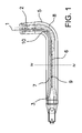
- Support 5 is drawn in Figure 1 , with electric wires 1, 2, a terminal 3, a separating partition 6, slots 7, 8 and stops 9, 10.
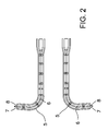
- Figure 2 represents an upper view of two connector axis without electric wires, the lower right side and the upper left side. Each illustrates support 5, two slots 7, 8 and the separating partition 6.
- Figure 3 illustrates the lower view of the two connector axis without electric wires, the lower right side and the upper left side. Each illustrates support 5 and stops 9, 10.
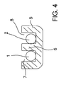
- Figure 4 shows support 5, with wires 1, 2 housed in their respective slots 7, 8 and separated by separating partition 6.
- Figure 5 shows another exemplary embodiment of support 5 formed by segments 11, 12, with separating partition 13, wires 1, 2 and securing means 14, 15.
- the procedure for the manufacture of a connector axis for a vehicle sunshield comprises at least two electric wires 1, 2 and terminals 3 at the ends of the referred wires, connected to a lamp and power supply respectively.
- the manufacturing system comprises the following stages:
- Support 5 is formed by a channel comprising separating partition 6 defining two slots 7, 8 for the location of respective wires 1, 2 in a separated, independent fashion; and another, as in Figure 5 comprising a support formed by a succession of segments, at least two segments 11, 12 comprising a separating partition 13, with securing means over wires 1, 2.
- support 5 may be made of the same material as that employed in the over-moulding operation, which would increase durability and connector axis strength. It also avoids possible points at which differences in material or colour appear and hence, the final product quality is superior.
- Separating partition 6, 13 of support 5 can also comprises a reinforcing metal core that would significantly reinforce the support.
- the lower part of support 5 is designed with stops or needles 9, 10 that allow the over-moulding to pass underneath support 5.
- said stops or needles 9, 10 maintain support 5 at the necessary height and width so that support 5 is centred during the over-moulding process.
- the final product consists of a connector axis for a vehicle sunshield in accordance with the previous procedure, of the type comprising at least two electric wires 1, 2 and terminals 3 at the ends of the referred wires in order to connect, as previously stated, a light source, such as a lighted mirror and power supply means.
- Said connector axis comprises support 5 where mentioned wires 1, 2 are housed, with said wires separated inside referred support 5, and with over-moulding over support 5 and wires 1, 2.
- One of supports 5 is formed by a channel comprising at least one separating partition 6 defining two slots 7, 8 for the location of separate independent respective wires 1, 2 ( Figs 1-4 ).
- the other possible support 5 ( Fig. 5 ) is formed by at least two segments 11, 12 comprising separating partition 13, with securing means 14, 15 over electric wires 1, 2.
- Said securing means 14, 15 prevent the wires 1, 2 from separating from support 5 during the over-moulding process.
- support 5 is of the same material as that used for over-moulding, which increases support 5, durability and strength.
- said partition can comprise a metal reinforcement core (not illustrated).
- support 5 comprises stops or needle 9, 10 in its upper and lower parts to facilitate the centring of said support 5.
- This invention describes a new procedure for manufacturing a connector axis for a vehicle sunshield and the connector axis obtained.
- the examples described here do not limit this invention and it can have various applications and/or adaptations, all within the scope of the following claims.
Landscapes
- Engineering & Computer Science (AREA)
- Mechanical Engineering (AREA)
- Manufacturing & Machinery (AREA)
- Multi-Conductor Connections (AREA)
- Cable Accessories (AREA)
- Processing Of Terminals (AREA)
- Injection Moulding Of Plastics Or The Like (AREA)
- Manufacturing Of Electrical Connectors (AREA)
Abstract
Description
- This is a method for manufacturing a connector axis for vehicle sunshield and connector axis thus obtained, which comprises at least two electrical wires and terminals at the ends of the referred wires and it because it comprises the following manufacturing stages: a first stage in which the mentioned wires are arranged on a support, with said wires separated on the referred support, a second stage in which said support is placed inside a mould and a third stage in which the support and wire assembly is moulded.
- Spanish Patent
ES2158818 - United States Patent
US 2008/0187614 , "Plastic positioning pin for overmolded product" from 2007, which refers to an over-moulded electronic device that includes a pre-mould part with protruding studs in contact with a cavity inside the mould. Arranged in this way, the studs are sealed inside the mould, which guarantees correct operation of the electronic device. - This invention is a great advance in the car industry, specifically in the area where the vehicle sunshield electronic connection is produced.
- It is specifically intended for sunshields of vehicles incorporating lighting in the mirror or other systems that require an electric or electronic connection.
- Said connections require outer protection because the use of the sunshield could cause the wires to twist.
- A moulding system is currently being employed in which metal sheets are initially available that are over-moulded and, once over-moulded, the electric wires can be connected or electric wires protected inside a metal pipe or without one.
- The main disadvantage is that the injection cycles are drastically reduced due to the need to have the sheets in the housings to prevent subsequent complications.
- The inventor has also seen that this traditional moulding procedure for the sheets also has the disadvantage that many have to be rejected in quality assurance controls because the sheets come out of the sides during injection.
- If wires are used instead of sheets, they sometime touch and when the covering is melted as a result of the high temperatures an electric short-circuit occurs.
- With this invention, apart from resolving the previously described problems, the inventor reduces the moulding times by approximately 50%, makes the final product mechanically stronger because the housings or moulder venting wires are removed and also provides greater dimensional stability to the product, above all, in critical areas, such as curves.
- This is achieved because the wires are laid out on a support that separates them to prevent them from touching and then the entire support and wire assembly is moulded.
- The final product is very strong because of the support and moulding, is safe since the wires are always separated and, at the same time, there is no danger of badly placed wires resulting in poor moulding that leaves part of the wires without any covering.
- One object of this invention for the manufacture of a connector axis for a vehicle sunshield, comprising at least two electric wires and terminals at the ends of the referred wires, characterised in that it comprises the following manufacturing stages: a first stage in which the mentioned wires are arranged on a support, with said wires separated on the referred support, a second stage in which said support with said wires is placed inside a mould and a third stage in which the support and wire assembly is moulded.
- Another objective of this invention is a connector axis for a vehicle sunshield in accordance with the pervious procedure of the type comprising at least two electric wires and terminals at the ends of the referred wires, characterised in that it comprises a support for the mentioned wires, with said wires separated by the referred support with the support and wires over-moulded.
- In order to facilitate the description, this report is accompanied by five sheets of drawings on which a practical exemplary embodiment is represented, which is cited as an example that does not limit the scope of this invention.
-
Figure 1 is an elevation view of the support with the installed wires, -
Figure 2 is an elevation view of the supports for the left and right sunshields without the electric wires, -
Figure 3 is a lower view of the supports for the left and right sunshields without the electric wires, -
Figure 4 is a cut along section IV-IV of the support inFigure 1 , -
Figure 5 is a perspective view of a support formed by segments. -
Support 5 is drawn inFigure 1 , withelectric wires terminal 3, a separatingpartition 6,slots stops -
Figure 2 represents an upper view of two connector axis without electric wires, the lower right side and the upper left side. Each illustratessupport 5, twoslots separating partition 6. -
Figure 3 illustrates the lower view of the two connector axis without electric wires, the lower right side and the upper left side. Each illustratessupport 5 and stops 9, 10. -
Figure 4 showssupport 5, withwires respective slots partition 6. - Finally,
Figure 5 shows another exemplary embodiment ofsupport 5 formed bysegments partition 13,wires - Thus, the procedure for the manufacture of a connector axis for a vehicle sunshield comprises at least two
electric wires terminals 3 at the ends of the referred wires, connected to a lamp and power supply respectively. - The manufacturing system comprises the following stages:
- A first stage in which mentioned
wires support 5 so that both wires are separated insidesupport 5. - A second stage in which, mentioned
support 5, is positioned withwires - Lastly, a third stage in which the support and wires of the first stage are moulded, with
wires support 5. - Basically, there are two types of supports, one as shown in
Figures 1 to 4 , in whichsupport 5 is formed by a channel comprising separatingpartition 6 defining twoslots respective wires Figure 5 comprising a support formed by a succession of segments, at least twosegments separating partition 13, with securing means overwires - A priori, with
support 5 ofFigures 1 to 4 , it would be possible to incorporate more wires and more separating partitions. The support inFigure 5 , on the other hand, would not allow this, although its segment arrangement makes it adaptable to any configuration with curves that might be required. - In the third stage for over-moulding,
support 5 may be made of the same material as that employed in the over-moulding operation, which would increase durability and connector axis strength. It also avoids possible points at which differences in material or colour appear and hence, the final product quality is superior. -
Separating partition support 5 can also comprises a reinforcing metal core that would significantly reinforce the support. - In order to facilitate the positioning inside the mould, the lower part of
support 5 is designed with stops orneedles support 5. Similarly, said stops orneedles support 5 at the necessary height and width so thatsupport 5 is centred during the over-moulding process. - In this fashion, the final product consists of a connector axis for a vehicle sunshield in accordance with the previous procedure, of the type comprising at least two
electric wires terminals 3 at the ends of the referred wires in order to connect, as previously stated, a light source, such as a lighted mirror and power supply means. - Said connector axis comprises
support 5 where mentionedwires support 5, and with over-moulding oversupport 5 andwires - One of
supports 5 is formed by a channel comprising at least one separatingpartition 6 defining twoslots respective wires 1, 2 (Figs 1-4 ). - The other possible support 5 (
Fig. 5 ) is formed by at least twosegments partition 13, withsecuring means electric wires - Said securing means 14, 15 prevent the
wires support 5 during the over-moulding process. - In a particular exemplary embodiment, as previously indicated,
support 5 is of the same material as that used for over-moulding, which increasessupport 5, durability and strength. - In order to reinforce
support 5 and said separatingpartition - As indicated in the procedure,
support 5 comprises stops orneedle support 5. - This invention describes a new procedure for manufacturing a connector axis for a vehicle sunshield and the connector axis obtained. The examples described here do not limit this invention and it can have various applications and/or adaptations, all within the scope of the following claims.
Claims (12)
- A procedure for the manufacture of a connector axis for a vehicle sunshield comprising at least two electric wires (1, 2) and terminals (3) at the ends of the referred wires, characterised in that it comprises the following manufacturing stages:• a first stage in which mentioned wires (1, 2) are arranged on support (5) so that both wires are separated on referred support (5).• a second stage in which mentioned support (5) is positioned with wires (1, 2) inside a mould, and• a third stage in which the support and wires assembly is moulded.
- Procedure in accordance with claim 1 characterised in that support (5) is formed by a channel comprising at least one separating partition (6), defining two slots (7, 8) for the location of respective separated independent wires (1, 2).
- Procedure in accordance with claim 1 characterised in that support (5) is formed by at least two segments (11, 12) comprising separating partition (13), with securing means over the wires (1, 2).
- Procedure in accordance with claim 1 characterised in that support (5) is of the same material as that used in over-moulding.
- Procedure in accordance with claim 2 or 3 characterised in that separating partition (6, 13) of support (5) has a metal reinforcement core.
- Procedure in accordance with claim 1 characterised in that support (5) comprises stop or needles (9, 10) in the upper and lower parts for centring.
- Connector axis for a vehicle sunshield in accordance with the previous procedure, of the type comprising at least two electric wires (1, 2) and terminals (3) at the ends of the referred wires characterised in that it comprises support (5) where mentioned wires (1, 2) are housed, with said wires separated inside referred support (5) and with over-moulding over support (5) and wires (1, 2).
- Connector axis in accordance with claim 7 characterised in that support (5) is formed by a channel comprising at least one separating partition (6) defining two slots (7, 8) for the location of separate independent respective wires (1, 2).
- Connector axis in accordance with claim 7 characterised in that support (5) is formed by at least two segments (11, 12) comprising separating partition (13), with securing means (14, 15) over electric wires (1, 2).
- Connector axis in accordance with claim 7 characterised in that support (5) is of the same material as that used in the over-moulding process.
- Connector axis in accordance with claim 8 or 9 characterised in that separating partition (6, 13) of support (5) comprises a metal reinforcement core.
- Connector axis in accordance with claim 7 characterised in that support (5) comprises stops or needles (9, 10) in its lower part.
Priority Applications (2)
| Application Number | Priority Date | Filing Date | Title |
|---|---|---|---|
| ES08382071.2T ES2622677T3 (en) | 2008-12-03 | 2008-12-03 | Procedure for manufacturing a connecting axle for vehicle sunshade and obtained connecting axle |
| EP08382071.2A EP2193906B1 (en) | 2008-12-03 | 2008-12-03 | Method for manufacturing a connector axis for vehicle sunshield and connector axis thus obtained |
Applications Claiming Priority (1)
| Application Number | Priority Date | Filing Date | Title |
|---|---|---|---|
| EP08382071.2A EP2193906B1 (en) | 2008-12-03 | 2008-12-03 | Method for manufacturing a connector axis for vehicle sunshield and connector axis thus obtained |
Publications (2)
| Publication Number | Publication Date |
|---|---|
| EP2193906A1 true EP2193906A1 (en) | 2010-06-09 |
| EP2193906B1 EP2193906B1 (en) | 2017-02-08 |
Family
ID=40601201
Family Applications (1)
| Application Number | Title | Priority Date | Filing Date |
|---|---|---|---|
| EP08382071.2A Active EP2193906B1 (en) | 2008-12-03 | 2008-12-03 | Method for manufacturing a connector axis for vehicle sunshield and connector axis thus obtained |
Country Status (2)
| Country | Link |
|---|---|
| EP (1) | EP2193906B1 (en) |
| ES (1) | ES2622677T3 (en) |
Citations (5)
| Publication number | Priority date | Publication date | Assignee | Title |
|---|---|---|---|---|
| EP0399368A1 (en) * | 1989-05-20 | 1990-11-28 | Eugen Zipperle Gmbh & Co. Kg | Sun visor for motor vehicles |
| US5143678A (en) * | 1990-03-13 | 1992-09-01 | Rockwell Abs - France | Angled support arm for a sun-visor which is electrically powered by conductors |
| ES2158818A1 (en) | 1999-12-07 | 2001-09-01 | Lear Automotive Eeds Spain | Method for injecting cable lead-throughs and centering/separating element to be used in said method |
| US20020063437A1 (en) * | 2000-11-29 | 2002-05-30 | Jason Mulder | Stamping reinforced polymeric molded elbow and method of manufacture |
| US20080187614A1 (en) | 2007-02-02 | 2008-08-07 | Siemens Vdo Automotive Corporation | Plastic positioning pin for overmolded product |
-
2008
- 2008-12-03 EP EP08382071.2A patent/EP2193906B1/en active Active
- 2008-12-03 ES ES08382071.2T patent/ES2622677T3/en active Active
Patent Citations (5)
| Publication number | Priority date | Publication date | Assignee | Title |
|---|---|---|---|---|
| EP0399368A1 (en) * | 1989-05-20 | 1990-11-28 | Eugen Zipperle Gmbh & Co. Kg | Sun visor for motor vehicles |
| US5143678A (en) * | 1990-03-13 | 1992-09-01 | Rockwell Abs - France | Angled support arm for a sun-visor which is electrically powered by conductors |
| ES2158818A1 (en) | 1999-12-07 | 2001-09-01 | Lear Automotive Eeds Spain | Method for injecting cable lead-throughs and centering/separating element to be used in said method |
| US20020063437A1 (en) * | 2000-11-29 | 2002-05-30 | Jason Mulder | Stamping reinforced polymeric molded elbow and method of manufacture |
| US20080187614A1 (en) | 2007-02-02 | 2008-08-07 | Siemens Vdo Automotive Corporation | Plastic positioning pin for overmolded product |
Non-Patent Citations (1)
| Title |
|---|
| "Procedimiento de inyecci6n de pasacables y elemento centrador/separador para utilizarlo con dicho procedimiento", LEAR AUTOMOTIVE (EEDS) SPAIN, S.L., 1999 |
Also Published As
| Publication number | Publication date |
|---|---|
| EP2193906B1 (en) | 2017-02-08 |
| ES2622677T3 (en) | 2017-07-07 |
Similar Documents
| Publication | Publication Date | Title |
|---|---|---|
| EP2266845B1 (en) | Method for laying and device for guiding and fixing cables of a harness in the interior of a housing of a lighting device of a motor vehicle | |
| EP2342784B1 (en) | Molded electrical socket | |
| US11784430B2 (en) | Method for producing an angled plug-in connector, an angled plug-in connector and a sensor | |
| KR101404499B1 (en) | Wiring system | |
| EP2743139B1 (en) | Electrical distribution center | |
| JPH04263913A (en) | Resin insertion molding method of metallic material | |
| DE102011077187B4 (en) | Shielding and production of such a shield | |
| MX2013006565A (en) | External Part Mounted Electric Wire, Wiring Harness Including the Same External Part Mounted Electric Wire, And Method for Fabricating the Same Wiring Harness. | |
| EP3196985B1 (en) | Electrical connection device and method for mounting an electrical connection device | |
| US3898371A (en) | Wiring harness and method of making same | |
| CN102483982B (en) | Winding body for a magnetic assembly of a solenoid valve and method for winding a winding wire onto a winding body | |
| DE4431026C2 (en) | Motor vehicle sensor | |
| EP2193906B1 (en) | Method for manufacturing a connector axis for vehicle sunshield and connector axis thus obtained | |
| EP0464347B1 (en) | Method for making a brake lining wear warning apparatus | |
| EP2767807B1 (en) | Cable fixation for sensor housing | |
| EP3728772B1 (en) | Vehicle door handle | |
| DE10164990B4 (en) | Motor vehicle door with one or more line connections and method for mounting the line connections | |
| EP1148223B1 (en) | Throttle valve actuator | |
| EP1410931A1 (en) | Air vent having a electronic component embedded therein | |
| DE102013215188A1 (en) | Socket component for charging opening of electric car, has fuse retainer defining fuse cavity, and wire secured at proximate end of terminal and comprising direct inline fuse attached to proximate end and arranged in retainer | |
| EP1849659A1 (en) | Vehicle interior trim part and method for manufacturing the same | |
| EP2781396A1 (en) | Cable connector assembly process, cable connector and set of cable connectors obtained by this process | |
| US20010031584A1 (en) | Hybrid plug housing and process for its production | |
| JP3623136B2 (en) | Insert molding method | |
| KR101728680B1 (en) | A method of a Flexible Flat Cable Assembly for Steering Rolling Connector of Vehicles |
Legal Events
| Date | Code | Title | Description |
|---|---|---|---|
| PUAI | Public reference made under article 153(3) epc to a published international application that has entered the european phase |
Free format text: ORIGINAL CODE: 0009012 |
|
| AK | Designated contracting states |
Kind code of ref document: A1 Designated state(s): AT BE BG CH CY CZ DE DK EE ES FI FR GB GR HR HU IE IS IT LI LT LU LV MC MT NL NO PL PT RO SE SI SK TR |
|
| AX | Request for extension of the european patent |
Extension state: AL BA MK RS |
|
| 17P | Request for examination filed |
Effective date: 20101209 |
|
| AKX | Designation fees paid |
Designated state(s): AT BE BG CH CY CZ DE DK EE ES FI FR GB GR HR HU IE IS IT LI LT LU LV MC MT NL NO PL PT RO SE SI SK TR |
|
| 17Q | First examination report despatched |
Effective date: 20130801 |
|
| GRAP | Despatch of communication of intention to grant a patent |
Free format text: ORIGINAL CODE: EPIDOSNIGR1 |
|
| INTG | Intention to grant announced |
Effective date: 20160721 |
|
| GRAS | Grant fee paid |
Free format text: ORIGINAL CODE: EPIDOSNIGR3 |
|
| GRAF | Information related to payment of grant fee modified |
Free format text: ORIGINAL CODE: EPIDOSCIGR3 |
|
| GRAA | (expected) grant |
Free format text: ORIGINAL CODE: 0009210 |
|
| AK | Designated contracting states |
Kind code of ref document: B1 Designated state(s): AT BE BG CH CY CZ DE DK EE ES FI FR GB GR HR HU IE IS IT LI LT LU LV MC MT NL NO PL PT RO SE SI SK TR |
|
| REG | Reference to a national code |
Ref country code: GB Ref legal event code: FG4D |
|
| REG | Reference to a national code |
Ref country code: CH Ref legal event code: EP Ref country code: AT Ref legal event code: REF Ref document number: 866667 Country of ref document: AT Kind code of ref document: T Effective date: 20170215 Ref country code: FR Ref legal event code: PLFP Year of fee payment: 10 |
|
| REG | Reference to a national code |
Ref country code: IE Ref legal event code: FG4D |
|
| REG | Reference to a national code |
Ref country code: DE Ref legal event code: R096 Ref document number: 602008048696 Country of ref document: DE |
|
| REG | Reference to a national code |
Ref country code: LT Ref legal event code: MG4D |
|
| REG | Reference to a national code |
Ref country code: NL Ref legal event code: MP Effective date: 20170208 |
|
| REG | Reference to a national code |
Ref country code: ES Ref legal event code: FG2A Ref document number: 2622677 Country of ref document: ES Kind code of ref document: T3 Effective date: 20170707 |
|
| REG | Reference to a national code |
Ref country code: AT Ref legal event code: MK05 Ref document number: 866667 Country of ref document: AT Kind code of ref document: T Effective date: 20170208 |
|
| PG25 | Lapsed in a contracting state [announced via postgrant information from national office to epo] |
Ref country code: HR Free format text: LAPSE BECAUSE OF FAILURE TO SUBMIT A TRANSLATION OF THE DESCRIPTION OR TO PAY THE FEE WITHIN THE PRESCRIBED TIME-LIMIT Effective date: 20170208 Ref country code: FI Free format text: LAPSE BECAUSE OF FAILURE TO SUBMIT A TRANSLATION OF THE DESCRIPTION OR TO PAY THE FEE WITHIN THE PRESCRIBED TIME-LIMIT Effective date: 20170208 Ref country code: GR Free format text: LAPSE BECAUSE OF FAILURE TO SUBMIT A TRANSLATION OF THE DESCRIPTION OR TO PAY THE FEE WITHIN THE PRESCRIBED TIME-LIMIT Effective date: 20170509 Ref country code: LT Free format text: LAPSE BECAUSE OF FAILURE TO SUBMIT A TRANSLATION OF THE DESCRIPTION OR TO PAY THE FEE WITHIN THE PRESCRIBED TIME-LIMIT Effective date: 20170208 Ref country code: NO Free format text: LAPSE BECAUSE OF FAILURE TO SUBMIT A TRANSLATION OF THE DESCRIPTION OR TO PAY THE FEE WITHIN THE PRESCRIBED TIME-LIMIT Effective date: 20170508 |
|
| PG25 | Lapsed in a contracting state [announced via postgrant information from national office to epo] |
Ref country code: AT Free format text: LAPSE BECAUSE OF FAILURE TO SUBMIT A TRANSLATION OF THE DESCRIPTION OR TO PAY THE FEE WITHIN THE PRESCRIBED TIME-LIMIT Effective date: 20170208 Ref country code: BG Free format text: LAPSE BECAUSE OF FAILURE TO SUBMIT A TRANSLATION OF THE DESCRIPTION OR TO PAY THE FEE WITHIN THE PRESCRIBED TIME-LIMIT Effective date: 20170508 Ref country code: SE Free format text: LAPSE BECAUSE OF FAILURE TO SUBMIT A TRANSLATION OF THE DESCRIPTION OR TO PAY THE FEE WITHIN THE PRESCRIBED TIME-LIMIT Effective date: 20170208 Ref country code: PT Free format text: LAPSE BECAUSE OF FAILURE TO SUBMIT A TRANSLATION OF THE DESCRIPTION OR TO PAY THE FEE WITHIN THE PRESCRIBED TIME-LIMIT Effective date: 20170608 Ref country code: NL Free format text: LAPSE BECAUSE OF FAILURE TO SUBMIT A TRANSLATION OF THE DESCRIPTION OR TO PAY THE FEE WITHIN THE PRESCRIBED TIME-LIMIT Effective date: 20170208 Ref country code: LV Free format text: LAPSE BECAUSE OF FAILURE TO SUBMIT A TRANSLATION OF THE DESCRIPTION OR TO PAY THE FEE WITHIN THE PRESCRIBED TIME-LIMIT Effective date: 20170208 |
|
| REG | Reference to a national code |
Ref country code: SK Ref legal event code: T3 Ref document number: E 23889 Country of ref document: SK |
|
| PG25 | Lapsed in a contracting state [announced via postgrant information from national office to epo] |
Ref country code: EE Free format text: LAPSE BECAUSE OF FAILURE TO SUBMIT A TRANSLATION OF THE DESCRIPTION OR TO PAY THE FEE WITHIN THE PRESCRIBED TIME-LIMIT Effective date: 20170208 Ref country code: RO Free format text: LAPSE BECAUSE OF FAILURE TO SUBMIT A TRANSLATION OF THE DESCRIPTION OR TO PAY THE FEE WITHIN THE PRESCRIBED TIME-LIMIT Effective date: 20170208 |
|
| REG | Reference to a national code |
Ref country code: DE Ref legal event code: R097 Ref document number: 602008048696 Country of ref document: DE |
|
| PG25 | Lapsed in a contracting state [announced via postgrant information from national office to epo] |
Ref country code: PL Free format text: LAPSE BECAUSE OF FAILURE TO SUBMIT A TRANSLATION OF THE DESCRIPTION OR TO PAY THE FEE WITHIN THE PRESCRIBED TIME-LIMIT Effective date: 20170208 Ref country code: DK Free format text: LAPSE BECAUSE OF FAILURE TO SUBMIT A TRANSLATION OF THE DESCRIPTION OR TO PAY THE FEE WITHIN THE PRESCRIBED TIME-LIMIT Effective date: 20170208 |
|
| PLBE | No opposition filed within time limit |
Free format text: ORIGINAL CODE: 0009261 |
|
| STAA | Information on the status of an ep patent application or granted ep patent |
Free format text: STATUS: NO OPPOSITION FILED WITHIN TIME LIMIT |
|
| 26N | No opposition filed |
Effective date: 20171109 |
|
| PG25 | Lapsed in a contracting state [announced via postgrant information from national office to epo] |
Ref country code: SI Free format text: LAPSE BECAUSE OF FAILURE TO SUBMIT A TRANSLATION OF THE DESCRIPTION OR TO PAY THE FEE WITHIN THE PRESCRIBED TIME-LIMIT Effective date: 20170208 |
|
| REG | Reference to a national code |
Ref country code: CH Ref legal event code: PL |
|
| GBPC | Gb: european patent ceased through non-payment of renewal fee |
Effective date: 20171203 |
|
| REG | Reference to a national code |
Ref country code: IE Ref legal event code: MM4A |
|
| PG25 | Lapsed in a contracting state [announced via postgrant information from national office to epo] |
Ref country code: MT Free format text: LAPSE BECAUSE OF NON-PAYMENT OF DUE FEES Effective date: 20171203 Ref country code: LU Free format text: LAPSE BECAUSE OF NON-PAYMENT OF DUE FEES Effective date: 20171203 |
|
| REG | Reference to a national code |
Ref country code: BE Ref legal event code: MM Effective date: 20171231 |
|
| PG25 | Lapsed in a contracting state [announced via postgrant information from national office to epo] |
Ref country code: IE Free format text: LAPSE BECAUSE OF NON-PAYMENT OF DUE FEES Effective date: 20171203 |
|
| PG25 | Lapsed in a contracting state [announced via postgrant information from national office to epo] |
Ref country code: BE Free format text: LAPSE BECAUSE OF NON-PAYMENT OF DUE FEES Effective date: 20171231 Ref country code: CH Free format text: LAPSE BECAUSE OF NON-PAYMENT OF DUE FEES Effective date: 20171231 Ref country code: GB Free format text: LAPSE BECAUSE OF NON-PAYMENT OF DUE FEES Effective date: 20171203 Ref country code: LI Free format text: LAPSE BECAUSE OF NON-PAYMENT OF DUE FEES Effective date: 20171231 |
|
| PG25 | Lapsed in a contracting state [announced via postgrant information from national office to epo] |
Ref country code: HU Free format text: LAPSE BECAUSE OF FAILURE TO SUBMIT A TRANSLATION OF THE DESCRIPTION OR TO PAY THE FEE WITHIN THE PRESCRIBED TIME-LIMIT; INVALID AB INITIO Effective date: 20081203 Ref country code: MC Free format text: LAPSE BECAUSE OF FAILURE TO SUBMIT A TRANSLATION OF THE DESCRIPTION OR TO PAY THE FEE WITHIN THE PRESCRIBED TIME-LIMIT Effective date: 20170208 |
|
| PG25 | Lapsed in a contracting state [announced via postgrant information from national office to epo] |
Ref country code: CY Free format text: LAPSE BECAUSE OF NON-PAYMENT OF DUE FEES Effective date: 20170208 |
|
| PG25 | Lapsed in a contracting state [announced via postgrant information from national office to epo] |
Ref country code: TR Free format text: LAPSE BECAUSE OF FAILURE TO SUBMIT A TRANSLATION OF THE DESCRIPTION OR TO PAY THE FEE WITHIN THE PRESCRIBED TIME-LIMIT Effective date: 20170208 |
|
| PG25 | Lapsed in a contracting state [announced via postgrant information from national office to epo] |
Ref country code: IS Free format text: LAPSE BECAUSE OF FAILURE TO SUBMIT A TRANSLATION OF THE DESCRIPTION OR TO PAY THE FEE WITHIN THE PRESCRIBED TIME-LIMIT Effective date: 20170608 |
|
| PGFP | Annual fee paid to national office [announced via postgrant information from national office to epo] |
Ref country code: DE Payment date: 20240628 Year of fee payment: 16 |
|
| PGFP | Annual fee paid to national office [announced via postgrant information from national office to epo] |
Ref country code: CZ Payment date: 20240529 Year of fee payment: 16 |
|
| PGFP | Annual fee paid to national office [announced via postgrant information from national office to epo] |
Ref country code: IT Payment date: 20240627 Year of fee payment: 16 |
|
| REG | Reference to a national code |
Ref country code: DE Ref legal event code: R119 Ref document number: 602008048696 Country of ref document: DE |
|
| PG25 | Lapsed in a contracting state [announced via postgrant information from national office to epo] |
Ref country code: CZ Free format text: LAPSE BECAUSE OF NON-PAYMENT OF DUE FEES Effective date: 20241203 |
|
| PG25 | Lapsed in a contracting state [announced via postgrant information from national office to epo] |
Ref country code: DE Free format text: LAPSE BECAUSE OF NON-PAYMENT OF DUE FEES Effective date: 20250701 |
|
| PG25 | Lapsed in a contracting state [announced via postgrant information from national office to epo] |
Ref country code: IT Free format text: LAPSE BECAUSE OF NON-PAYMENT OF DUE FEES Effective date: 20241203 |
|
| PGFP | Annual fee paid to national office [announced via postgrant information from national office to epo] |
Ref country code: FR Payment date: 20251223 Year of fee payment: 18 |
|
| PGFP | Annual fee paid to national office [announced via postgrant information from national office to epo] |
Ref country code: SK Payment date: 20251201 Year of fee payment: 18 |
|
| PGFP | Annual fee paid to national office [announced via postgrant information from national office to epo] |
Ref country code: ES Payment date: 20260330 Year of fee payment: 18 |