EP2193672B1 - Distributed fault-tolerant voice message system for independent mobile telephony networks - Google Patents
Distributed fault-tolerant voice message system for independent mobile telephony networks Download PDFInfo
- Publication number
- EP2193672B1 EP2193672B1 EP08789075A EP08789075A EP2193672B1 EP 2193672 B1 EP2193672 B1 EP 2193672B1 EP 08789075 A EP08789075 A EP 08789075A EP 08789075 A EP08789075 A EP 08789075A EP 2193672 B1 EP2193672 B1 EP 2193672B1
- Authority
- EP
- European Patent Office
- Prior art keywords
- vms
- independent mobile
- voice message
- mobile system
- msc
- Prior art date
- Legal status (The legal status is an assumption and is not a legal conclusion. Google has not performed a legal analysis and makes no representation as to the accuracy of the status listed.)
- Not-in-force
Links
Images


Classifications
-
- H—ELECTRICITY
- H04—ELECTRIC COMMUNICATION TECHNIQUE
- H04W—WIRELESS COMMUNICATION NETWORKS
- H04W4/00—Services specially adapted for wireless communication networks; Facilities therefor
- H04W4/12—Messaging; Mailboxes; Announcements
-
- H—ELECTRICITY
- H04—ELECTRIC COMMUNICATION TECHNIQUE
- H04M—TELEPHONIC COMMUNICATION
- H04M3/00—Automatic or semi-automatic exchanges
- H04M3/42—Systems providing special services or facilities to subscribers
- H04M3/50—Centralised arrangements for answering calls; Centralised arrangements for recording messages for absent or busy subscribers ; Centralised arrangements for recording messages
- H04M3/53—Centralised arrangements for recording incoming messages, i.e. mailbox systems
- H04M3/533—Voice mail systems
- H04M3/53308—Message originator indirectly connected to the message centre, e.g. after detection of busy or absent state of a called party
-
- H—ELECTRICITY
- H04—ELECTRIC COMMUNICATION TECHNIQUE
- H04M—TELEPHONIC COMMUNICATION
- H04M2203/00—Aspects of automatic or semi-automatic exchanges
- H04M2203/45—Aspects of automatic or semi-automatic exchanges related to voicemail messaging
- H04M2203/4536—Voicemail combined with text-based messaging
-
- H—ELECTRICITY
- H04—ELECTRIC COMMUNICATION TECHNIQUE
- H04M—TELEPHONIC COMMUNICATION
- H04M3/00—Automatic or semi-automatic exchanges
- H04M3/42—Systems providing special services or facilities to subscribers
- H04M3/50—Centralised arrangements for answering calls; Centralised arrangements for recording messages for absent or busy subscribers ; Centralised arrangements for recording messages
- H04M3/53—Centralised arrangements for recording incoming messages, i.e. mailbox systems
- H04M3/533—Voice mail systems
-
- H—ELECTRICITY
- H04—ELECTRIC COMMUNICATION TECHNIQUE
- H04M—TELEPHONIC COMMUNICATION
- H04M3/00—Automatic or semi-automatic exchanges
- H04M3/42—Systems providing special services or facilities to subscribers
- H04M3/50—Centralised arrangements for answering calls; Centralised arrangements for recording messages for absent or busy subscribers ; Centralised arrangements for recording messages
- H04M3/53—Centralised arrangements for recording incoming messages, i.e. mailbox systems
- H04M3/533—Voice mail systems
- H04M3/53325—Interconnection arrangements between voice mail systems
-
- H—ELECTRICITY
- H04—ELECTRIC COMMUNICATION TECHNIQUE
- H04M—TELEPHONIC COMMUNICATION
- H04M3/00—Automatic or semi-automatic exchanges
- H04M3/42—Systems providing special services or facilities to subscribers
- H04M3/50—Centralised arrangements for answering calls; Centralised arrangements for recording messages for absent or busy subscribers ; Centralised arrangements for recording messages
- H04M3/53—Centralised arrangements for recording incoming messages, i.e. mailbox systems
- H04M3/533—Voice mail systems
- H04M3/53333—Message receiving aspects
- H04M3/53341—Message reply
Definitions
- the present invention is directed, in general, to communications systems and, more specifically, to apparatus and methods for providing voice message services to a user of a mobile terminal in a communications network having independent mobile telephony systems.
- a voice message, or "voice mail,” system is typically implemented in a centralized server in commercial mobile telephony networks.
- the network components such as Mobile Switching Center (MSC), Short Message Service Center (SMS-C) and Radio Access Network (RAN) subsystems, are typically physically-connected to form a network that can cover vast geographical areas.
- MSC Mobile Switching Center
- SMS-C Short Message Service Center
- RAN Radio Access Network
- Such a scaled-down system also referred to as a Compact System, is capable of providing service to mobile stations within its radio coverage area without being dependent on physical connectivity to any other telecommunications infrastructure; the system is completely self-contained and is capable of stand-alone operation.
- a centralized VMS may not be accessible all the time. Furthermore, if a centralized VMS is relied upon, it becomes a single-point of failure. Thus, in such scenarios, it would be advantageous to have a distributed VMS solution that can provide voice mail service to mobile stations even if the serving independent mobile system is operating in stand-alone mode. Accordingly, there is a need in the art for improved apparatus and methods for providing voice message services to a user of a mobile terminal in a communications network having independent mobile telephony systems.
- WO 99/57914 shows a system for providing a roaming subscriber with access to services available in a first telephone network, when subscriber is roaming in a second telephone network that includes a packet-switch network connecting the first telephone network with the second telephone network. Messages in the voice mailbox of the first telephone network are transferred via a first service node, the IP network, and a second service node to a temporary mailbox of the second telephone network. A retrieval notification sent to the mobile telephone includes a short code which when dialled gives the mobile telephone access to the temporary mailbox.
- a voice message to a user of a mobile station (MS) in a communications network having at least first and second independent mobile systems.
- Each of the independent mobile systems includes a Mobile Switching Center (MSC), Short Message Service Center (SMS-C) and Voice Message System (VMS).
- MSC Mobile Switching Center
- SMS-C Short Message Service Center
- VMS Voice Message System
- the MSC, SMS-C and VMS of each independent mobile system are physically co-located.
- the call request When a call request for a MS is received, the call request is routed to the MS through a MSC of an independent mobile system currently serving the MS. If the MS does not answer the call request, the calling party can leave a voice message in a VMS.
- the VMS requests that a SMS-C transmit an SMS notification message to the MS.
- the SMS notification message includes the unique identifier code of the VMS of the independent mobile system in which the voice message is stored, whereby the MS can retrieve the voice message by placing a call to the unique identifier code of the VMS.
- the MS can retrieve the voice message when being served by any independent mobile system. To do so, the MS sends a request for the voice message, which is received by the MSC of the independent mobile system currently serving the MS; the request is directed to the unique identifier code of the VMS which received the voice message.
- the request for the voice message is routed from the MSC of the independent mobile system currently serving the MS to the VMS storing the voice message, which can then cause the voice message to be transmitted to the MS
- the transmission of a voice message from a VMS to a MS includes transmitting the voice message to a Media Gateway (MGW) of the independent mobile system in which the message was stored, which then transmits the voice message to the MS through a MGW of the independent mobile system then serving the MS.
- MGW Media Gateway
- a MS can retrieve a plurality of voice messages stored by a plurality of VMSs when being served by any independent mobile system.
- the MS sends a request for all voice messages, which is received by the MSC of the independent mobile system currently serving the MS; the request is directed to a common identifier code for voice messages, whereby the voice message request is routed from the MSC of the independent mobile system currently serving the MS to a VMS of that independent mobile system. That VMS then requests each individual voice message for the MS stored on each VMS of all independent mobile systems in the communications network. Each voice message is then transmitted to the MS. In one embodiment, each voice message is transmitted directly from the VMS storing it to the MS.
- each individual voice message is received at the VMS of the independent mobile system currently serving the MS. That VMS then transmits each individual voice message to a Media Gateway (MGW) of the independent mobile system currently serving the MS, which then transmits the voice message to the MS.
- MGW Media Gateway
- each VMS includes an indexing service that identifies each voice message stored on each VMS of all independent mobile systems in the communications network.
- the indexing service can catalog each voice message for stored on each VMS of all independent mobile systems in the communications network by periodically polling each VMS or, alternatively, in response to automatically receiving updates from each VMS in the communication network.
- FIGURE 1 illustrated is the signalling related to the storing of a voice message, and notification thereof to a mobile station (MS), in a communications network having at least first and second independent mobile systems (101-A, 101-B).
- Each of the independent mobile systems includes a Mobile Switching Center (MSC; 102-A, 102-B)), Short Message Service Center (SMS-C; 103-A, 103-B) and Voice Message System (VMS; 104-A, 104-B).
- the MSC, SMS-C and VMS of each independent mobile system can be physically co-located, such as in a compact system for mobile military applications.
- a call request 111 for a MS is received, for example from MS 105-A for MS 105-B, the call request 111 is routed to the MS 105-B through the MSC 102-B of the independent mobile system 101-B currently serving the MS 105-B.
- the call request 111 is first received by the MSC 102-A currently serving the calling MS 105-A.
- the MSC 102-A then routes the call request 112 to the MSC 102-B of the independent mobile system 101-B currently serving the called MS 105-B.
- the calling party can leave a voice message.
- the voice message is stored in the VMS of the independent mobile system through which the call request is received.
- the call request 111 is received at MSC 102-A of independent mobile system 101-A.
- the calling party is directed to leave a voice message 113-A in VMS 104-A.
- the VMS 104-A then requests 114-A that a SMS-C 103-A of the independent mobile system 101-A transmit an SMS notification message 115-A to the MS 105-B; the SMS notification message 115-A is routed (116) by MSC 102-A to MSC 102-B then serving the called MS 105-B, and then routed (117) from the MSC 102-B to the MS 105-B.
- the voice message is stored in the VMS 104-B of the independent mobile system 101-B currently serving the MS 105-B.
- the VMS 104-B then requests 114-B that a SMS-C 103-B of the independent mobile system 101-B transmit an SMS notification message 115-B to the MS 105-B.
- the SMS notification message is first routed (115) from the SMS-C 103-B to the MSC 102-B (115), and then routed (117) from the MSC 102-B to the MS 105-B.
- the SMS notification message includes a unique identifier code of the VMS where the message is stored, whereby the MS 105-B can retrieve the voice message by placing a call to the unique identifier code of the VMS, regardless of which independent mobile system is serving the MS 105-B at the time of requesting the voice message; this capability is illustrated in FIGURE 2 .
- FIGURE 2 illustrated is first exemplary signalling related to the retrieval of a voice message by a MS when being served by any independent mobile system.
- a voice message for MS 105-B was stored in VMS 104-B of independent mobile system 101-B.
- the MS 105-B is being served by independent mobile system 201 at the time a request is made for the voice message.
- the MS 105-B sends a request 211 for the voice message, which is received by the MSC 202 of the independent mobile system 201 currently serving the MS; the request is directed to the unique identifier code of the VMS 104-B of the independent mobile system 101-B which received the voice message.
- the request for the voice message (VM Request) is routed (212) from the MSC 202 of the independent mobile system 201 currently serving the MS 105-B to the VMS 104-B storing the voice message, which can then cause the voice message to be transmitted to the MS.
- the VM Request is first routed (212) from the MSC 202 to the MSC 102-B, and then routed (213) from the MSC 102-B to the VMS 104-B.
- the VMS 104-B transmits the voice message to MS 105-B.
- the voice message is transmitted (214) to a Media Gateway (MGW) of the independent mobile system 101-B in which the message was stored, which then transmits the voice message to the MS 105-B through a MGW of the independent mobile system 201 then serving the MS.
- MGW Media Gateway
- the MGWs are physically-integrated with the MSCs of each independent mobile system; the MGWs, however, may be, or may be hosted by, separate physical entities.
- a MS can retrieve a plurality of voice messages stored by a plurality of VMSs when being served by any independent mobile system.
- the MS 105-B sends a request for all voice messages (311), which is received by the MSC 202 of the independent mobile system 201 currently serving the MS; the request is directed to a common identifier code for voice messages.
- the voice message request is routed from the MSC 202 to the VMS 204 of that independent mobile system.
- the VMS 204 requests each individual voice message for the MS 105-B stored on each VMS of all independent mobile systems in the communications network. Each voice message is then transmitted to the MS 105-B.
- each VMS can include an indexing service that identifies each voice message stored on each VMS of all independent mobile systems in the communications network.
- the indexing service can catalog each voice message stored on each VMS of all independent mobile systems in the communications network by periodically polling each VMS or, alternatively, in response to automatically receiving updates from each VMS in the communication network.
- the VMS 204 can cause the transmission of a voice message stored on the VMS 104-B of another independent mobile system 101-B by sending a voice message request to the remote VMS 104-B, which then routes the voice message to the MS 105-B.
- the voice message request from VMS 204 is first routed (313) to MSC 202, then routed (314) to the MSC 102-B, and then routed (315) to the VMS 104-B.
- the VMS 104-B transmits the voice message to MS 105-B.
- the voice message is transmitted (316) to a Media Gateway (MGW) of the independent mobile system 101-B in which the message was stored, which then transmits the voice message to the MS 105-B through a MGW of the independent mobile system 201 then serving the MS.
- the voice message can be routed (317) from MGW 102-B to MGW 202, and then directly routed (320) to the MS 105-B.
- a voice message may be first routed (318) from MSC 202 to VMS 204, which can then control the routing (319) to MS 105-B through MGW 202.
- the invention described herein modifies the standard user experience with voice mail where a single number is dialed to access the user's mailbox.
- the invention has the particular advantage of distributing voice mails across a group of independent mobile systems, thus avoiding a single point of failure. Failure of a single independent mobile system, or VMS, will only cause the loss of voice messages stored in that system; such a failure will not prevent new voice messages from being stored and retrieved as would be the case if all voice mails were stored on a centralized server. Furthermore, if a system or link outage is not permanent, a user will regain access to all stored voice messages without any manual configuration. Storing voice messages in multiple systems also allows a compact system to be built with low-cost, low capacity components that are better suited to rugged and mobile applications, such as military and disaster recovery deployments.
Landscapes
- Engineering & Computer Science (AREA)
- Signal Processing (AREA)
- Computer Networks & Wireless Communication (AREA)
- Mobile Radio Communication Systems (AREA)
- Telephonic Communication Services (AREA)
Abstract
Description
- The present invention is directed, in general, to communications systems and, more specifically, to apparatus and methods for providing voice message services to a user of a mobile terminal in a communications network having independent mobile telephony systems.
- A voice message, or "voice mail," system (VMS) is typically implemented in a centralized server in commercial mobile telephony networks. In such networks, the network components, such as Mobile Switching Center (MSC), Short Message Service Center (SMS-C) and Radio Access Network (RAN) subsystems, are typically physically-connected to form a network that can cover vast geographical areas. For military, civil defense or disaster recovery operations, however, it is advantageous to deploy many portable, independent, "network-in-a-box," systems which each contain a RAN as well as the core network components. Such a scaled-down system, also referred to as a Compact System, is capable of providing service to mobile stations within its radio coverage area without being dependent on physical connectivity to any other telecommunications infrastructure; the system is completely self-contained and is capable of stand-alone operation.
- In a deployment scenario with independent mobile systems that are either physically-mobile or are stationary but deployed in remote areas with intermittent satellite or microwave links, a centralized VMS may not be accessible all the time. Furthermore, if a centralized VMS is relied upon, it becomes a single-point of failure. Thus, in such scenarios, it would be advantageous to have a distributed VMS solution that can provide voice mail service to mobile stations even if the serving independent mobile system is operating in stand-alone mode. Accordingly, there is a need in the art for improved apparatus and methods for providing voice message services to a user of a mobile terminal in a communications network having independent mobile telephony systems. Preferably, such improved apparatus and methods will provide fault-tolerance to allow for continued VMS services throughout the communications network if a single VMS should fail.
WO 99/57914 - To address the above-discussed deficiencies of the prior art, disclosed are systems and methods for providing a voice message to a user of a mobile station (MS) in a communications network having at least first and second independent mobile systems. Each of the independent mobile systems includes a Mobile Switching Center (MSC), Short Message Service Center (SMS-C) and Voice Message System (VMS). In one embodiment, the MSC, SMS-C and VMS of each independent mobile system are physically co-located.
- When a call request for a MS is received, the call request is routed to the MS through a MSC of an independent mobile system currently serving the MS. If the MS does not answer the call request, the calling party can leave a voice message in a VMS. The VMS then requests that a SMS-C transmit an SMS notification message to the MS. The SMS notification message includes the unique identifier code of the VMS of the independent mobile system in which the voice message is stored, whereby the MS can retrieve the voice message by placing a call to the unique identifier code of the VMS.
- The MS can retrieve the voice message when being served by any independent mobile system. To do so, the MS sends a request for the voice message, which is received by the MSC of the independent mobile system currently serving the MS; the request is directed to the unique identifier code of the VMS which received the voice message. The request for the voice message is routed from the MSC of the independent mobile system currently serving the MS to the VMS storing the voice message, which can then cause the voice message to be transmitted to the MS In one embodiment, the transmission of a voice message from a VMS to a MS includes transmitting the voice message to a Media Gateway (MGW) of the independent mobile system in which the message was stored, which then transmits the voice message to the MS through a MGW of the independent mobile system then serving the MS.
- In one embodiment, a MS can retrieve a plurality of voice messages stored by a plurality of VMSs when being served by any independent mobile system. In such embodiments, the MS sends a request for all voice messages, which is received by the MSC of the independent mobile system currently serving the MS; the request is directed to a common identifier code for voice messages, whereby the voice message request is routed from the MSC of the independent mobile system currently serving the MS to a VMS of that independent mobile system. That VMS then requests each individual voice message for the MS stored on each VMS of all independent mobile systems in the communications network. Each voice message is then transmitted to the MS. In one embodiment, each voice message is transmitted directly from the VMS storing it to the MS. In an alternate embodiment, each individual voice message is received at the VMS of the independent mobile system currently serving the MS. That VMS then transmits each individual voice message to a Media Gateway (MGW) of the independent mobile system currently serving the MS, which then transmits the voice message to the MS.
- In one embodiment, each VMS includes an indexing service that identifies each voice message stored on each VMS of all independent mobile systems in the communications network. The indexing service can catalog each voice message for stored on each VMS of all independent mobile systems in the communications network by periodically polling each VMS or, alternatively, in response to automatically receiving updates from each VMS in the communication network.
- The foregoing has outlined, rather broadly, the principles of the present invention so that those skilled in the art may better understand the detailed description of the exemplary embodiments that follow. Those skilled in the art should appreciate that they can readily use the disclosed conception and exemplary embodiments as a basis for designing or modifying other structures and methods for carrying out the same purposes of the present invention.
- For a more complete understanding of the invention, reference is now made to the following detailed description taken in conjunction with the accompanying drawings, in which:
-
FIGURE 1 illustrates the signalling related to the storing of a voice message, and notification thereof, according to the principles of the invention; -
FIGURE 2 illustrates first exemplary signalling related to the retrieval of a voice message, according to the principles of the invention; and, -
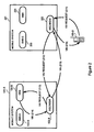
FIGURE 3 illustrates second exemplary signalling rotated to the retrieval of a voice message, according to the principles of the invention. - Referring to
FIGURE 1 , illustrated is the signalling related to the storing of a voice message, and notification thereof to a mobile station (MS), in a communications network having at least first and second independent mobile systems (101-A, 101-B). Each of the independent mobile systems includes a Mobile Switching Center (MSC; 102-A, 102-B)), Short Message Service Center (SMS-C; 103-A, 103-B) and Voice Message System (VMS; 104-A, 104-B). The MSC, SMS-C and VMS of each independent mobile system can be physically co-located, such as in a compact system for mobile military applications. - When a
call request 111 for a MS is received, for example from MS 105-A for MS 105-B, thecall request 111 is routed to the MS 105-B through the MSC 102-B of the independent mobile system 101-B currently serving the MS 105-B. In the illustrated example, thecall request 111 is first received by the MSC 102-A currently serving the calling MS 105-A. The MSC 102-A then routes thecall request 112 to the MSC 102-B of the independent mobile system 101-B currently serving the called MS 105-B. - If the called MS 105-B does not answer the call request, or the MS 105-B is configured to automatically route calls to voicemail (e.g., unconditional call forwarding), the calling party can leave a voice message. In one embodiment, the voice message is stored in the VMS of the independent mobile system through which the call request is received. For example, in
Figure 1 , thecall request 111 is received at MSC 102-A of independent mobile system 101-A. When MS 105-B does not answer the call request, the calling party is directed to leave a voice message 113-A in VMS 104-A. The VMS 104-A then requests 114-A that a SMS-C 103-A of the independent mobile system 101-A transmit an SMS notification message 115-A to the MS 105-B; the SMS notification message 115-A is routed (116) by MSC 102-A to MSC 102-B then serving the called MS 105-B, and then routed (117) from the MSC 102-B to the MS 105-B. In an alternate embodiments, the voice message is stored in the VMS 104-B of the independent mobile system 101-B currently serving the MS 105-B. In this embodiments, The VMS 104-B then requests 114-B that a SMS-C 103-B of the independent mobile system 101-B transmit an SMS notification message 115-B to the MS 105-B. As illustrated inFIGURE 1 , the SMS notification message is first routed (115) from the SMS-C 103-B to the MSC 102-B (115), and then routed (117) from the MSC 102-B to the MS 105-B. In both embodiments, the SMS notification message includes a unique identifier code of the VMS where the message is stored, whereby the MS 105-B can retrieve the voice message by placing a call to the unique identifier code of the VMS, regardless of which independent mobile system is serving the MS 105-B at the time of requesting the voice message; this capability is illustrated inFIGURE 2 . - Turning now to
FIGURE 2 , illustrated is first exemplary signalling related to the retrieval of a voice message by a MS when being served by any independent mobile system. As illustrated inFIGURE 1 , a voice message for MS 105-B was stored in VMS 104-B of independent mobile system 101-B. InFIGURE 2 , however, the MS 105-B is being served by independentmobile system 201 at the time a request is made for the voice message. To retrieve the voice message, the MS 105-B sends arequest 211 for the voice message, which is received by the MSC 202 of the independentmobile system 201 currently serving the MS; the request is directed to the unique identifier code of the VMS 104-B of the independent mobile system 101-B which received the voice message. The request for the voice message (VM Request) is routed (212) from the MSC 202 of the independentmobile system 201 currently serving the MS 105-B to the VMS 104-B storing the voice message, which can then cause the voice message to be transmitted to the MS. As illustrated inFIGURE 2 , the VM Request is first routed (212) from theMSC 202 to the MSC 102-B, and then routed (213) from the MSC 102-B to the VMS 104-B. - In response to receiving the voice message request (213), the VMS 104-B transmits the voice message to MS 105-B. In one embodiment, the voice message is transmitted (214) to a Media Gateway (MGW) of the independent mobile system 101-B in which the message was stored, which then transmits the voice message to the MS 105-B through a MGW of the independent
mobile system 201 then serving the MS. As illustrated inFIGURE 2 , the MGWs are physically-integrated with the MSCs of each independent mobile system; the MGWs, however, may be, or may be hosted by, separate physical entities. - Finally, referring to
FIGURE 3 , illustrated is second exemplary signalling related to the retrieval of a voice message by a MS when being served by any independent mobile system. In this embodiment, a MS can retrieve a plurality of voice messages stored by a plurality of VMSs when being served by any independent mobile system. In such embodiments, the MS 105-B sends a request for all voice messages (311), which is received by the MSC 202 of the independentmobile system 201 currently serving the MS; the request is directed to a common identifier code for voice messages. The voice message request is routed from the MSC 202 to the VMS 204 of that independent mobile system. The VMS 204 then requests each individual voice message for the MS 105-B stored on each VMS of all independent mobile systems in the communications network. Each voice message is then transmitted to the MS 105-B. - In order to manage the transmission of all voice messages stored by a plurality of VMSs, each VMS can include an indexing service that identifies each voice message stored on each VMS of all independent mobile systems in the communications network. The indexing service can catalog each voice message stored on each VMS of all independent mobile systems in the communications network by periodically polling each VMS or, alternatively, in response to automatically receiving updates from each VMS in the communication network.
- Based on the contents of the index, the
VMS 204 can cause the transmission of a voice message stored on the VMS 104-B of another independent mobile system 101-B by sending a voice message request to the remote VMS 104-B, which then routes the voice message to the MS 105-B. As illustrated inFIGURE 3 , the voice message request fromVMS 204 is first routed (313) toMSC 202, then routed (314) to the MSC 102-B, and then routed (315) to the VMS 104-B. In response to receiving the voice message request (315), the VMS 104-B transmits the voice message to MS 105-B. - In one embodiment, the voice message is transmitted (316) to a Media Gateway (MGW) of the independent mobile system 101-B in which the message was stored, which then transmits the voice message to the MS 105-B through a MGW of the independent
mobile system 201 then serving the MS. The voice message can be routed (317) from MGW 102-B toMGW 202, and then directly routed (320) to the MS 105-B. Alternatively, a voice message may be first routed (318) fromMSC 202 toVMS 204, which can then control the routing (319) to MS 105-B throughMGW 202. - The invention described herein modifies the standard user experience with voice mail where a single number is dialed to access the user's mailbox. The invention has the particular advantage of distributing voice mails across a group of independent mobile systems, thus avoiding a single point of failure. Failure of a single independent mobile system, or VMS, will only cause the loss of voice messages stored in that system; such a failure will not prevent new voice messages from being stored and retrieved as would be the case if all voice mails were stored on a centralized server. Furthermore, if a system or link outage is not permanent, a user will regain access to all stored voice messages without any manual configuration. Storing voice messages in multiple systems also allows a compact system to be built with low-cost, low capacity components that are better suited to rugged and mobile applications, such as military and disaster recovery deployments.
- Although the invention has been described in detail, those skilled in the art will conceive of various changes, substitutions and alterations to the exemplary embodiments described herein without departing from the spirit and scope of the invention in its broadest form. The exemplary embodiments presented herein illustrate the principles of the invention and are not intended to be exhaustive or to limit the invention to the form disclosed; it is intended that the scope of the invention be defined by the claims appended hereto, and their equivalents.
Claims (16)
- A method for providing a voice message to a user of a mobile station MS in a communications network having at least first and second independent mobile systems, each of said independent mobile systems including a Mobile Switching Center MSC, Short Message Service Center SMS-C and Voice Message System VMS, wherein each said VMS is identified by a unique identifier code, said method comprising the steps of:receiving a call request (111) for a MS at a first MSC (102-A) of a first independent mobile system;routing said call request from said first MSC (102-A) to said MS through a second MSC (102-B) of a second independent mobile system, said second independent mobile system currently serving said MS (105-B);if said MS (105-B) does not answer said call, storing a voice message in a Voice Mail System VMS of said first or second independent mobile system; (101-A, 101-B) requesting (114-B), by said VMS, that a Short Message Service Center SMS-C transmit an SMS notification message (117) to said MS; and,transmitting, by said SMS-C, said SMS notification message (117) to said MS through said second MSC, said SMS notification message including the unique identifier code of said VMS, whereby said MS (105-B) can retrieve said voice message by placing a call to said unique identifier code of said VMS when being served by any independent mobile system; (211)wherein said MS can retrieve a plurality of voice messages stored by a plurality of VMSs when being served by any independent mobile system, said method further comprising the steps of:receiving a request (311) from said MS, at an MSC of said any independent mobile system currently serving said MS, for all voice messages, said request directed to a common identifier code for voice messages, wherebysaid request (311) for said all voice messages from said MSC of said any independent mobile system currently serving said MS is routed to a VMS of said any independent mobile system;requesting, by said VMS of said any independent mobile system currently serving said MS, each individual voice message for said MS stored on each VMS of all independent mobile systems in the communications network; and,transmitting each said individual voice message to said MS, (320),
- The method recited in claim 1, wherein said MS can retrieve said voice message when being served by any independent mobile system, said method further comprising the steps of:receiving a request for said voice message from said MS at an MSC of said any independent mobile system, said request directed to said unique identifier code of said VMS received in said SMS notification message;routing said request for said voice message from said MSC of said any independent mobile system to said VMS ;receiving said request for said voice message at said VMS; and,transmitting said voice message from said VMS to said MS.
- The method recited in claim 2, wherein said step of routing said request for said voice message from said MSC of said any independent mobile system to said VMS comprises the steps of:routing said request for said voice message from said MSC of said any independent mobile system to said first or second MSC of said first or second independent mobile system; and,routing said request for said voice message from said first or second MSC of said first or second independent mobile system to said VMS.
- The method recited in claim 3, wherein said step of transmitting said voice message from said VMS to said MS comprises the steps of:transmitting said voice message to a Media Gateway MGW of said any independent mobile system; and,transmitting said voice message from said MOW of said any independent mobile system to said MS.
- The method recited in claim 1, wherein the MSC, SMS-C and VMS of each said independent mobile system are physically co-located.
- The method recited in claim 1, wherein said step of transmitting each said individual voice message to said MS comprises the steps of:receiving each said individual voice message at said VMS of said any independent mobile system currently serving said MS;transmitting each said individual voice message to a Media Gateway MGW of said any independent mobile system currently serving said MS; and,transmitting each said individual voice message to said MS from said MGW of said any independent mobile system currently serving said MS.
- The method recited in claim 1, wherein said VMS of said any independent mobile system includes an indexing service that identifies each voice message for said MS stored on each VMS of all independent mobile systems in the communications network.
- The method recited in claim 7, wherein said indexing service catalogs each voice message for said MS stored on each VMS of all independent mobile systems in the communications network- by periodically polling each VMS, or- in response to automatically receiving updates from each VMS in the communication network.
- A communications network operative to provide a voice message to a user of a mobile station MS, said communications network comprising:at least first and second independent mobile systems,each of said independent mobile systems including a Mobile Switching Center MSC, Short Message Service Center SMS-C and voice Message System VMS, wherein each said VMS is identified by a unique identifier code,said communications network operative to:receive a call request (111) for a MS at a first MSC (102-A) of a first independent mobile system;route said call request from said first-MSC to said MSthrough a second MSC (102-B) of a second independent mobile system, said second independent mobile system currently serving said MS (105-B)if said MS (105-B) does not answer said call, store a voice message in a VMS of said first or second independent mobile system (101-A, 101-B)request, by said VMS, that a Short Message Service Center SMS-C transmit an SMS notification message to said MS; and,transmit, by said SMS-C, said SMS notification message (117) to said
MS through said second MSC, said SMS notification message including the unique identifier code of said VMS of said second independent mobile system, whereby said MS (105-B) can retrieve said voice message by placing a call to said unique identifier code of said VMS when being served by any independent mobile system (211)
wherein said MS can retrieve a plurality of voice messages stored by a plurality of VMSs when being served by any independent mobile system, said communications network further operative to:receive a request (311) from said MS, at an MSC of said any independent mobile system currently serving said MS, for all voice messages, said request directed to a common identifier code for voice messages, wherebysaid request (311) for said all voice messages from said MSC of said any independent mobile system currently serving said MS is routed to a VMS of said any independent mobile system;request, by said VMS of said any independent mobile system currently serving said MS, each individual voice message for said MS stored on each VMS of all independent mobile systems in the communications network; and,transmit each said individual voice message to said MS (320). - The communications network recited in claim 9, wherein said MS can retrieve said voice message when being served by any independent mobile system, said communications network further operative to:receive a request for said voice message from said MS at an MSC of said any independent mobile system; said request directed to said unique identifier code of said VMS;route said request for said voice message from said MSC of said any independent mobile system to said VMS;receive said request for said VM at said VMS; and,transmit said voice message from said VMS to said MS.
- The communications network recited in claim 10, wherein said communications network, when routing said request for said voice message from said MSC of said any independent mobile system to said VMS, is further operative to:route said request for said voice message from said MSC of said any independent mobile system to said first or second MSC of said first or second independent mobile system; and,route said request for said voice message from said first or second MSC of said first or second independent mobile system to said VMS.
- The communications network recited in claim 11, wherein said communications network, when transmitting said voice message from said VMS, is further operative to:transmit said voice message to a Media Gateway MGW of said any independent mobile system; and,transmit said voice message from said MGW of said any independent mobile system to said MS.
- The communications network recited in claim 9, wherein the MSC, SMSC and VMS of each said independent mobile system are physically co-located.
- The communications network recited in claim 9, wherein said communication network, when transmitting each said individual voice message to said MS, is further operative to:receive each said individual voice message at said VMS of said any independent mobile system currently serving said MS;transmit each said individual voice message to a Media Gateway MGW of said any independent mobile system currently serving said MS; and,transmit each said individual voice message to said MS from said MGW of said any independent mobile system currently serving said MS.
- The communications network recited in claim 9, wherein said VMS of said any independent mobile system includes an indexing service that identifies each voice message for said MS stored on each VMS of all independent mobile systems in the communications network.
- The communications network recited in claim 15, wherein said indexing service catalogs each voice message for said MS stored on each SMS of all independent mobile systems in the communications network- by periodically polling each VMS, or- in response to automatically receiving updates from each VMS in the communication network.
Applications Claiming Priority (2)
| Application Number | Priority Date | Filing Date | Title |
|---|---|---|---|
| US11/839,865 US8099083B2 (en) | 2007-08-16 | 2007-08-16 | Distributed fault-tolerant voice message system for independent mobile telephony networks |
| PCT/IB2008/002126 WO2009022219A1 (en) | 2007-08-16 | 2008-08-12 | Distributed fault-tolerant voice message system for independent mobile telephony networks |
Publications (2)
| Publication Number | Publication Date |
|---|---|
| EP2193672A1 EP2193672A1 (en) | 2010-06-09 |
| EP2193672B1 true EP2193672B1 (en) | 2012-01-04 |
Family
ID=40095472
Family Applications (1)
| Application Number | Title | Priority Date | Filing Date |
|---|---|---|---|
| EP08789075A Not-in-force EP2193672B1 (en) | 2007-08-16 | 2008-08-12 | Distributed fault-tolerant voice message system for independent mobile telephony networks |
Country Status (7)
| Country | Link |
|---|---|
| US (1) | US8099083B2 (en) |
| EP (1) | EP2193672B1 (en) |
| JP (1) | JP5324576B2 (en) |
| CN (1) | CN101828412B (en) |
| AT (1) | ATE540543T1 (en) |
| ES (1) | ES2376024T3 (en) |
| WO (1) | WO2009022219A1 (en) |
Families Citing this family (1)
| Publication number | Priority date | Publication date | Assignee | Title |
|---|---|---|---|---|
| CN104579907A (en) * | 2013-10-21 | 2015-04-29 | 中兴通讯股份有限公司 | Fusion method and device for VMS and instant message system |
Family Cites Families (11)
| Publication number | Priority date | Publication date | Assignee | Title |
|---|---|---|---|---|
| DE69535840D1 (en) * | 1994-11-04 | 2008-10-23 | Ntt Docomo Inc | Mobile communication system and method with message storage functionality |
| JP3652734B2 (en) * | 1995-05-11 | 2005-05-25 | 富士通株式会社 | Voice mail system |
| US6925299B1 (en) * | 1998-05-05 | 2005-08-02 | Starhome Gmbh | System and method for providing access to value added services for roaming users of mobile telephones |
| WO2000007350A1 (en) * | 1998-07-28 | 2000-02-10 | British Telecommunications Public Limited Company | Voice messaging system |
| US6504915B1 (en) | 1998-09-25 | 2003-01-07 | Unisys Corporation | Multiple node messaging system wherein nodes have shared access to message stores of other nodes |
| US6282416B1 (en) * | 1998-12-28 | 2001-08-28 | Nortel Networks Limited | Voice mail deposit for wireless mobile telephone networks |
| JP2001223803A (en) * | 2000-02-10 | 2001-08-17 | Nec Eng Ltd | Voice mail message system and interface control system using it |
| JP2001245053A (en) * | 2000-02-28 | 2001-09-07 | Hitachi Ltd | Answering machine message management system and mobile phone used for it |
| US6577712B2 (en) | 2000-04-07 | 2003-06-10 | Telefonaktiebolaget Lm Ericsson (Publ) | Distributed voice mail system |
| US6950876B2 (en) * | 2001-03-19 | 2005-09-27 | Lucent Technologies Inc. | Multiple-protocol home location register and method of use |
| US7801534B2 (en) * | 2003-12-11 | 2010-09-21 | Sprint Spectrum L.P. | Method and system for conveying location-granularity preferences with location-based service requests |
-
2007
- 2007-08-16 US US11/839,865 patent/US8099083B2/en not_active Expired - Fee Related
-
2008
- 2008-08-12 WO PCT/IB2008/002126 patent/WO2009022219A1/en not_active Ceased
- 2008-08-12 JP JP2010520641A patent/JP5324576B2/en not_active Expired - Fee Related
- 2008-08-12 CN CN200880111774.4A patent/CN101828412B/en not_active Expired - Fee Related
- 2008-08-12 EP EP08789075A patent/EP2193672B1/en not_active Not-in-force
- 2008-08-12 ES ES08789075T patent/ES2376024T3/en active Active
- 2008-08-12 AT AT08789075T patent/ATE540543T1/en active
Also Published As
| Publication number | Publication date |
|---|---|
| EP2193672A1 (en) | 2010-06-09 |
| CN101828412B (en) | 2013-01-30 |
| ES2376024T3 (en) | 2012-03-08 |
| US8099083B2 (en) | 2012-01-17 |
| CN101828412A (en) | 2010-09-08 |
| JP2010537462A (en) | 2010-12-02 |
| WO2009022219A1 (en) | 2009-02-19 |
| JP5324576B2 (en) | 2013-10-23 |
| US20090047935A1 (en) | 2009-02-19 |
| ATE540543T1 (en) | 2012-01-15 |
Similar Documents
| Publication | Publication Date | Title |
|---|---|---|
| US8775674B2 (en) | Systems and methods for seamless communications recovery and backup using networked communication devices | |
| US8537663B2 (en) | Systems and methods for seamless communications recovery and backup | |
| JP2005160094A (en) | System for providing interoperability of call pickup service in aproprietary enterprise communication network and cellular communication network | |
| EP2259653B1 (en) | Mobile based services for hotel PBX | |
| CA2578657C (en) | Method, system and apparatuses for short message group-delivering | |
| CN1149376A (en) | Connection release in a telecommunications system | |
| WO2012145040A1 (en) | Short message service center (smsc) message distributor | |
| US8837702B2 (en) | Method and system for communication forwarding | |
| US20100075700A1 (en) | Flexible capacity short message service center (SMSC) | |
| US7471673B2 (en) | IP telephone system having a hold function and a callback function | |
| US8099083B2 (en) | Distributed fault-tolerant voice message system for independent mobile telephony networks | |
| EP3039840B1 (en) | Communication system and method for mobile devices in the absence of cellular coverage | |
| US8503441B2 (en) | Method of managing a call addressed to a terminal associated to an access device | |
| EA007376B1 (en) | Method and system for transmitting a short message | |
| US20120242450A1 (en) | Communication System and Method | |
| CN1332573C (en) | Device and method for realizing to provide short news to mobile phone user and no interference service | |
| US9106755B2 (en) | Method and system for a gateway transfer | |
| JP7380879B2 (en) | Notification device, notification system, notification method and program | |
| KR101977707B1 (en) | Method and system for providing mobile general directory number service | |
| KR100814796B1 (en) | SMS system of all active structure | |
| KR101026048B1 (en) | System and method for providing outgoing information on incoming call | |
| JP5652006B2 (en) | Relay system, terminal device, short message relay method, and computer program | |
| KR20050106379A (en) | Method and system for receiving using smsc and variating selectively the notifying method for the uncompleted call information in the mobile telecommunication network | |
| KR20100122370A (en) | System and method for connection to first reciever | |
| EP1924923A2 (en) | System for delivering user-generated short-text notified multimedia messages between operator networks |
Legal Events
| Date | Code | Title | Description |
|---|---|---|---|
| PUAI | Public reference made under article 153(3) epc to a published international application that has entered the european phase |
Free format text: ORIGINAL CODE: 0009012 |
|
| 17P | Request for examination filed |
Effective date: 20100316 |
|
| AK | Designated contracting states |
Kind code of ref document: A1 Designated state(s): AT BE BG CH CY CZ DE DK EE ES FI FR GB GR HR HU IE IS IT LI LT LU LV MC MT NL NO PL PT RO SE SI SK TR |
|
| AX | Request for extension of the european patent |
Extension state: AL BA MK RS |
|
| RIN1 | Information on inventor provided before grant (corrected) |
Inventor name: OMAROUAYACHE, BADIS Inventor name: DERBYSHIRE, AMY Inventor name: BERGERON, JEAN-FRANCOIS Inventor name: RAMACHANDRAN, SETHURAMAN Inventor name: TRUCHAN, CATHERINE |
|
| 17Q | First examination report despatched |
Effective date: 20100917 |
|
| DAX | Request for extension of the european patent (deleted) | ||
| GRAP | Despatch of communication of intention to grant a patent |
Free format text: ORIGINAL CODE: EPIDOSNIGR1 |
|
| GRAS | Grant fee paid |
Free format text: ORIGINAL CODE: EPIDOSNIGR3 |
|
| GRAA | (expected) grant |
Free format text: ORIGINAL CODE: 0009210 |
|
| AK | Designated contracting states |
Kind code of ref document: B1 Designated state(s): AT BE BG CH CY CZ DE DK EE ES FI FR GB GR HR HU IE IS IT LI LT LU LV MC MT NL NO PL PT RO SE SI SK TR |
|
| REG | Reference to a national code |
Ref country code: GB Ref legal event code: FG4D |
|
| REG | Reference to a national code |
Ref country code: CH Ref legal event code: EP Ref country code: DE Ref legal event code: R082 Ref document number: 602008012516 Country of ref document: DE Representative=s name: HOFFMANN - EITLE, DE Ref country code: DE Ref legal event code: R082 Ref document number: 602008012516 Country of ref document: DE Representative=s name: HOFFMANN - EITLE PATENT- UND RECHTSANWAELTE PA, DE |
|
| REG | Reference to a national code |
Ref country code: AT Ref legal event code: REF Ref document number: 540543 Country of ref document: AT Kind code of ref document: T Effective date: 20120115 |
|
| REG | Reference to a national code |
Ref country code: CH Ref legal event code: NV Representative=s name: ISLER & PEDRAZZINI AG |
|
| REG | Reference to a national code |
Ref country code: IE Ref legal event code: FG4D |
|
| REG | Reference to a national code |
Ref country code: ES Ref legal event code: FG2A Ref document number: 2376024 Country of ref document: ES Kind code of ref document: T3 Effective date: 20120308 Ref country code: DE Ref legal event code: R096 Ref document number: 602008012516 Country of ref document: DE Effective date: 20120308 |
|
| REG | Reference to a national code |
Ref country code: NL Ref legal event code: VDEP Effective date: 20120104 |
|
| PG25 | Lapsed in a contracting state [announced via postgrant information from national office to epo] |
Ref country code: SI Free format text: LAPSE BECAUSE OF FAILURE TO SUBMIT A TRANSLATION OF THE DESCRIPTION OR TO PAY THE FEE WITHIN THE PRESCRIBED TIME-LIMIT Effective date: 20120104 |
|
| LTIE | Lt: invalidation of european patent or patent extension |
Effective date: 20120104 |
|
| PG25 | Lapsed in a contracting state [announced via postgrant information from national office to epo] |
Ref country code: NO Free format text: LAPSE BECAUSE OF FAILURE TO SUBMIT A TRANSLATION OF THE DESCRIPTION OR TO PAY THE FEE WITHIN THE PRESCRIBED TIME-LIMIT Effective date: 20120404 Ref country code: BG Free format text: LAPSE BECAUSE OF FAILURE TO SUBMIT A TRANSLATION OF THE DESCRIPTION OR TO PAY THE FEE WITHIN THE PRESCRIBED TIME-LIMIT Effective date: 20120404 Ref country code: LT Free format text: LAPSE BECAUSE OF FAILURE TO SUBMIT A TRANSLATION OF THE DESCRIPTION OR TO PAY THE FEE WITHIN THE PRESCRIBED TIME-LIMIT Effective date: 20120104 Ref country code: NL Free format text: LAPSE BECAUSE OF FAILURE TO SUBMIT A TRANSLATION OF THE DESCRIPTION OR TO PAY THE FEE WITHIN THE PRESCRIBED TIME-LIMIT Effective date: 20120104 Ref country code: HR Free format text: LAPSE BECAUSE OF FAILURE TO SUBMIT A TRANSLATION OF THE DESCRIPTION OR TO PAY THE FEE WITHIN THE PRESCRIBED TIME-LIMIT Effective date: 20120104 Ref country code: IS Free format text: LAPSE BECAUSE OF FAILURE TO SUBMIT A TRANSLATION OF THE DESCRIPTION OR TO PAY THE FEE WITHIN THE PRESCRIBED TIME-LIMIT Effective date: 20120504 |
|
| PG25 | Lapsed in a contracting state [announced via postgrant information from national office to epo] |
Ref country code: PL Free format text: LAPSE BECAUSE OF FAILURE TO SUBMIT A TRANSLATION OF THE DESCRIPTION OR TO PAY THE FEE WITHIN THE PRESCRIBED TIME-LIMIT Effective date: 20120104 Ref country code: FI Free format text: LAPSE BECAUSE OF FAILURE TO SUBMIT A TRANSLATION OF THE DESCRIPTION OR TO PAY THE FEE WITHIN THE PRESCRIBED TIME-LIMIT Effective date: 20120104 Ref country code: GR Free format text: LAPSE BECAUSE OF FAILURE TO SUBMIT A TRANSLATION OF THE DESCRIPTION OR TO PAY THE FEE WITHIN THE PRESCRIBED TIME-LIMIT Effective date: 20120405 Ref country code: PT Free format text: LAPSE BECAUSE OF FAILURE TO SUBMIT A TRANSLATION OF THE DESCRIPTION OR TO PAY THE FEE WITHIN THE PRESCRIBED TIME-LIMIT Effective date: 20120504 Ref country code: LV Free format text: LAPSE BECAUSE OF FAILURE TO SUBMIT A TRANSLATION OF THE DESCRIPTION OR TO PAY THE FEE WITHIN THE PRESCRIBED TIME-LIMIT Effective date: 20120104 |
|
| REG | Reference to a national code |
Ref country code: AT Ref legal event code: MK05 Ref document number: 540543 Country of ref document: AT Kind code of ref document: T Effective date: 20120104 |
|
| PG25 | Lapsed in a contracting state [announced via postgrant information from national office to epo] |
Ref country code: CY Free format text: LAPSE BECAUSE OF FAILURE TO SUBMIT A TRANSLATION OF THE DESCRIPTION OR TO PAY THE FEE WITHIN THE PRESCRIBED TIME-LIMIT Effective date: 20120104 |
|
| PG25 | Lapsed in a contracting state [announced via postgrant information from national office to epo] |
Ref country code: SE Free format text: LAPSE BECAUSE OF FAILURE TO SUBMIT A TRANSLATION OF THE DESCRIPTION OR TO PAY THE FEE WITHIN THE PRESCRIBED TIME-LIMIT Effective date: 20120104 Ref country code: DK Free format text: LAPSE BECAUSE OF FAILURE TO SUBMIT A TRANSLATION OF THE DESCRIPTION OR TO PAY THE FEE WITHIN THE PRESCRIBED TIME-LIMIT Effective date: 20120104 Ref country code: EE Free format text: LAPSE BECAUSE OF FAILURE TO SUBMIT A TRANSLATION OF THE DESCRIPTION OR TO PAY THE FEE WITHIN THE PRESCRIBED TIME-LIMIT Effective date: 20120104 Ref country code: CZ Free format text: LAPSE BECAUSE OF FAILURE TO SUBMIT A TRANSLATION OF THE DESCRIPTION OR TO PAY THE FEE WITHIN THE PRESCRIBED TIME-LIMIT Effective date: 20120104 Ref country code: RO Free format text: LAPSE BECAUSE OF FAILURE TO SUBMIT A TRANSLATION OF THE DESCRIPTION OR TO PAY THE FEE WITHIN THE PRESCRIBED TIME-LIMIT Effective date: 20120104 |
|
| PLBE | No opposition filed within time limit |
Free format text: ORIGINAL CODE: 0009261 |
|
| STAA | Information on the status of an ep patent application or granted ep patent |
Free format text: STATUS: NO OPPOSITION FILED WITHIN TIME LIMIT |
|
| PG25 | Lapsed in a contracting state [announced via postgrant information from national office to epo] |
Ref country code: IT Free format text: LAPSE BECAUSE OF FAILURE TO SUBMIT A TRANSLATION OF THE DESCRIPTION OR TO PAY THE FEE WITHIN THE PRESCRIBED TIME-LIMIT Effective date: 20120104 Ref country code: SK Free format text: LAPSE BECAUSE OF FAILURE TO SUBMIT A TRANSLATION OF THE DESCRIPTION OR TO PAY THE FEE WITHIN THE PRESCRIBED TIME-LIMIT Effective date: 20120104 |
|
| 26N | No opposition filed |
Effective date: 20121005 |
|
| PG25 | Lapsed in a contracting state [announced via postgrant information from national office to epo] |
Ref country code: AT Free format text: LAPSE BECAUSE OF FAILURE TO SUBMIT A TRANSLATION OF THE DESCRIPTION OR TO PAY THE FEE WITHIN THE PRESCRIBED TIME-LIMIT Effective date: 20120104 |
|
| REG | Reference to a national code |
Ref country code: DE Ref legal event code: R097 Ref document number: 602008012516 Country of ref document: DE Effective date: 20121005 |
|
| PG25 | Lapsed in a contracting state [announced via postgrant information from national office to epo] |
Ref country code: MC Free format text: LAPSE BECAUSE OF NON-PAYMENT OF DUE FEES Effective date: 20120831 |
|
| REG | Reference to a national code |
Ref country code: IE Ref legal event code: MM4A |
|
| PG25 | Lapsed in a contracting state [announced via postgrant information from national office to epo] |
Ref country code: IE Free format text: LAPSE BECAUSE OF NON-PAYMENT OF DUE FEES Effective date: 20120812 |
|
| PG25 | Lapsed in a contracting state [announced via postgrant information from national office to epo] |
Ref country code: MT Free format text: LAPSE BECAUSE OF FAILURE TO SUBMIT A TRANSLATION OF THE DESCRIPTION OR TO PAY THE FEE WITHIN THE PRESCRIBED TIME-LIMIT Effective date: 20120104 |
|
| PG25 | Lapsed in a contracting state [announced via postgrant information from national office to epo] |
Ref country code: TR Free format text: LAPSE BECAUSE OF FAILURE TO SUBMIT A TRANSLATION OF THE DESCRIPTION OR TO PAY THE FEE WITHIN THE PRESCRIBED TIME-LIMIT Effective date: 20120104 |
|
| PG25 | Lapsed in a contracting state [announced via postgrant information from national office to epo] |
Ref country code: LU Free format text: LAPSE BECAUSE OF NON-PAYMENT OF DUE FEES Effective date: 20120812 |
|
| PG25 | Lapsed in a contracting state [announced via postgrant information from national office to epo] |
Ref country code: HU Free format text: LAPSE BECAUSE OF FAILURE TO SUBMIT A TRANSLATION OF THE DESCRIPTION OR TO PAY THE FEE WITHIN THE PRESCRIBED TIME-LIMIT Effective date: 20080812 |
|
| REG | Reference to a national code |
Ref country code: FR Ref legal event code: PLFP Year of fee payment: 9 |
|
| REG | Reference to a national code |
Ref country code: FR Ref legal event code: PLFP Year of fee payment: 10 |
|
| REG | Reference to a national code |
Ref country code: FR Ref legal event code: PLFP Year of fee payment: 11 |
|
| PGFP | Annual fee paid to national office [announced via postgrant information from national office to epo] |
Ref country code: DE Payment date: 20190828 Year of fee payment: 12 Ref country code: FR Payment date: 20190826 Year of fee payment: 12 Ref country code: ES Payment date: 20190902 Year of fee payment: 12 |
|
| PGFP | Annual fee paid to national office [announced via postgrant information from national office to epo] |
Ref country code: BE Payment date: 20190827 Year of fee payment: 12 |
|
| PGFP | Annual fee paid to national office [announced via postgrant information from national office to epo] |
Ref country code: GB Payment date: 20190827 Year of fee payment: 12 |
|
| PGFP | Annual fee paid to national office [announced via postgrant information from national office to epo] |
Ref country code: CH Payment date: 20190903 Year of fee payment: 12 |
|
| REG | Reference to a national code |
Ref country code: DE Ref legal event code: R119 Ref document number: 602008012516 Country of ref document: DE |
|
| REG | Reference to a national code |
Ref country code: CH Ref legal event code: PL |
|
| GBPC | Gb: european patent ceased through non-payment of renewal fee |
Effective date: 20200812 |
|
| PG25 | Lapsed in a contracting state [announced via postgrant information from national office to epo] |
Ref country code: CH Free format text: LAPSE BECAUSE OF NON-PAYMENT OF DUE FEES Effective date: 20200831 Ref country code: LI Free format text: LAPSE BECAUSE OF NON-PAYMENT OF DUE FEES Effective date: 20200831 |
|
| REG | Reference to a national code |
Ref country code: BE Ref legal event code: MM Effective date: 20200831 |
|
| PG25 | Lapsed in a contracting state [announced via postgrant information from national office to epo] |
Ref country code: FR Free format text: LAPSE BECAUSE OF NON-PAYMENT OF DUE FEES Effective date: 20200831 Ref country code: DE Free format text: LAPSE BECAUSE OF NON-PAYMENT OF DUE FEES Effective date: 20210302 |
|
| PG25 | Lapsed in a contracting state [announced via postgrant information from national office to epo] |
Ref country code: BE Free format text: LAPSE BECAUSE OF NON-PAYMENT OF DUE FEES Effective date: 20200831 Ref country code: GB Free format text: LAPSE BECAUSE OF NON-PAYMENT OF DUE FEES Effective date: 20200812 |
|
| REG | Reference to a national code |
Ref country code: ES Ref legal event code: FD2A Effective date: 20220110 |
|
| PG25 | Lapsed in a contracting state [announced via postgrant information from national office to epo] |
Ref country code: ES Free format text: LAPSE BECAUSE OF NON-PAYMENT OF DUE FEES Effective date: 20200813 |