EP2192696A1 - Wireless communications method and system with spatial multiplexing using dually polarized antennas and corresponding receiver - Google Patents
Wireless communications method and system with spatial multiplexing using dually polarized antennas and corresponding receiver Download PDFInfo
- Publication number
- EP2192696A1 EP2192696A1 EP08170266A EP08170266A EP2192696A1 EP 2192696 A1 EP2192696 A1 EP 2192696A1 EP 08170266 A EP08170266 A EP 08170266A EP 08170266 A EP08170266 A EP 08170266A EP 2192696 A1 EP2192696 A1 EP 2192696A1
- Authority
- EP
- European Patent Office
- Prior art keywords
- receive
- signal
- signals
- antennas
- transmit
- Prior art date
- Legal status (The legal status is an assumption and is not a legal conclusion. Google has not performed a legal analysis and makes no representation as to the accuracy of the status listed.)
- Granted
Links
- 238000000034 method Methods 0.000 title claims abstract description 29
- 230000010287 polarization Effects 0.000 claims abstract description 83
- 239000013598 vector Substances 0.000 claims abstract description 62
- 238000012545 processing Methods 0.000 claims abstract description 30
- 238000012937 correction Methods 0.000 claims description 37
- 239000002131 composite material Substances 0.000 claims description 24
- 230000005540 biological transmission Effects 0.000 claims description 11
- 230000009471 action Effects 0.000 claims description 10
- 230000000694 effects Effects 0.000 claims description 7
- 238000004590 computer program Methods 0.000 claims description 3
- 239000011159 matrix material Substances 0.000 description 22
- 230000008569 process Effects 0.000 description 7
- 238000013461 design Methods 0.000 description 5
- 238000010586 diagram Methods 0.000 description 5
- 238000007476 Maximum Likelihood Methods 0.000 description 3
- 230000003247 decreasing effect Effects 0.000 description 3
- 238000005516 engineering process Methods 0.000 description 3
- 230000007423 decrease Effects 0.000 description 2
- 238000001514 detection method Methods 0.000 description 2
- 230000001627 detrimental effect Effects 0.000 description 2
- 230000009466 transformation Effects 0.000 description 2
- 230000008901 benefit Effects 0.000 description 1
- 230000001413 cellular effect Effects 0.000 description 1
- 238000001816 cooling Methods 0.000 description 1
- 230000006870 function Effects 0.000 description 1
- 230000003116 impacting effect Effects 0.000 description 1
- 238000005259 measurement Methods 0.000 description 1
- 230000000750 progressive effect Effects 0.000 description 1
- 230000005855 radiation Effects 0.000 description 1
- 102220004588 rs104893797 Human genes 0.000 description 1
- 102220040529 rs587778360 Human genes 0.000 description 1
- 238000005070 sampling Methods 0.000 description 1
- 238000010408 sweeping Methods 0.000 description 1
- 230000001360 synchronised effect Effects 0.000 description 1
Images


Classifications
-
- H—ELECTRICITY
- H04—ELECTRIC COMMUNICATION TECHNIQUE
- H04B—TRANSMISSION
- H04B7/00—Radio transmission systems, i.e. using radiation field
- H04B7/02—Diversity systems; Multi-antenna system, i.e. transmission or reception using multiple antennas
- H04B7/04—Diversity systems; Multi-antenna system, i.e. transmission or reception using multiple antennas using two or more spaced independent antennas
- H04B7/0413—MIMO systems
-
- H—ELECTRICITY
- H04—ELECTRIC COMMUNICATION TECHNIQUE
- H04B—TRANSMISSION
- H04B7/00—Radio transmission systems, i.e. using radiation field
- H04B7/02—Diversity systems; Multi-antenna system, i.e. transmission or reception using multiple antennas
- H04B7/10—Polarisation diversity; Directional diversity
Definitions
- This invention relates to wireless communications
- MIMO Multiple antenna
- the first column represents the symbol combinations transmitted during a first symbol interval and the second column represents the symbol combinations transmitted during the second symbol interval.
- the first row of the matrix gives the symbol combinations transmitted from the first transmit antenna, and the second row of the matrix gives the symbol combinations transmitted from the second antenna.
- the complexity of the maximum likelihood (ML) decoder of this code is proportional to M 2 , where M is the size of the signal constellation.
- the global objective of the present invention is to provide a method for limiting said increase of the complexity factor.
- one specific aim although not limiting the range of the invention, would be to provide a design concept which simplifies the implementation of 4 ⁇ 4 MIMO systems to the level of the complexity of 2 ⁇ 2 MIMO systems, or to provide a solution for 2K ⁇ 2K MIMO system designs whose optimum detection complexity would be on the same order of magnitude as that of K ⁇ K MIMO systems.
- the invention relates to a method for transmitting radio signals, including the following steps: for transmission, from a transmit device,
- an eigen vector is a vector having a direction which is "devoted" to this vector, i.e. for which another eigen vector has no component on that direction. In the present Euclidian space, these vectors have orthogonal directions.
- the two parallel channels provide data which are synchronous between both channels, and, consequently, the interference on one receive symbol is only due to the "parallel" symbol, on the parallel channel.
- the process for canceling the interference is thus easy.
- This invention provides a new concept for providing two channels in parallel.
- the bits are transmitted by processing them by batch, each batch defining a symbol signal having two orthogonal components, namely a real component and an imaginary component. It implies a complex processing load for coding the signals and decoding them in the receiver.
- the invention can be regarded as having shifted the load, of providing an orthogonal feature to the signal, from the two electronic ends of the transmission channel (encoder, decoder) to the physical channel.
- a major advantage is that, once the tilt or needed rotation correction of the antennas is estimated, its value can be kept for the following received data, as long as the antennas are supposed to be maintained in the same orientation.
- the data processing load of the invention is however quite limited since it is related to the physical orientation of the antennas. It means that there is no processing of each symbol, since the processing is globally made on the stream. Consequently, the processing rate for tracking the antennas' mutual polarization directions is of many orders of magnitude under the one of symbols processing.
- the invention can provide a slave antenna associated with processing circuits, said slave antenna being always viewed, by the receive decoding circuits, as being parallel with a master, transmit or receive, antenna even if one of these two cooperating antennas changes its direction. It is a wobbly toy effect.
- the invention thus implies two main functions.
- the first one which provides the tilt measurement at step e), is located in the receive device.
- the second one relates to the corrective action to be carried out. This action, for canceling the polarization tilt, can be carried out whether at the "effect" level or at the "cause” level.
- the corrective action can be a signal processing action in the receive device.
- the corrective action can be an action for rotating the polarization direction of the corresponding antenna, whether of the receive device or of the transmit device.
- the receiver would determine the relative mismatch or tilt of the receive antennas versus the transmit antennas, step e), and it would transmit back a request, or remote control, message for causing the transmit antennas to tilt according to the needed correction angle. It means that the transmit device would have a receive capability for a service, or beacon, channel.
- the transmit or receive antenna can be physically tilted by an actuator or tilt compensation elements, like elementary antennas around each antenna, can be provided and more or less activated for canceling, by phase opposition, the unwanted polarization component.
- the invention is very useful in a wireless communications system, for instance a cellular telephone system, where the antennas of the portable phone sets are directed in any random direction in use.
- these phone sets can now receive and transmit very high rate data, for instance moving pictures.
- the correction action is carried out in the receive device, by computing an interference component, of said first receive signal on said second receive signal, based on said correction angle, and subtracting said interference component from said second receive signal for upgrading it into a second eigen vector signal representing a second one of the two related transmit signals.
- the first of said receive signals is used, firstly, as a service signal, for determining the tilt, by computing the first eigen vector signal, and secondly, the first of said receive signals is used as a "payload" signal for transmitting data, together with the second one.
- an interference component, of said second receive signal on said first receive signal is computed, based on said correction angle, and is subtracted from said first eigen vector in order to improve it into a corrected first eigen vector.
- the tilt correction is thus improved.
- an improved interference component, of said corrected first eigen vector on said second receive signal is computed, based on said correction angle, and is subtracted from said second receive signal for obtaining a corrected second eigen vector signal representing said second one of the two related transmit signals.
- the first plurality and the second plurality are of a same size.
- the third plurality and the fourth plurality can be of a same size.
- the first plurality together with the second plurality are of a same size as the third plurality together with the fourth plurality.
- the invention also relates to a communications system for transmitting radio signals, including :
- the first plurality is, for instance, of two first transmit antennas and the second plurality is of two second transmit antennas.
- the invention also relates to a receive device for a communications system as above, including :
- the receive device is, for instance, a mobile device.
- the invention also relates to a computer program product which can be downloaded from a communications network and/or stored on a storage medium which can be read by a computer and/or processed by a processor, characterized in that it contains program code instructions for the embodiment of the method according to the invention, when said program is run on a computer.
- Such a computer program product can include instructions useful for the transmit device or useful for the receive device.
- the invention also deals with a storage means, which can be read by a computer, storing a set of instructions which can be run on said computer for embodying the method according to the invention.
- the invention method is used for designing a MIMO system in which a first plurality of half (N) the number 2N of transmit antennas of a transmit device, or station, transmit their signals in a first polarization direction 1D and a second plurality of the other half number N of transmit antennas transmit in a second polarization direction 2D which is the related orthogonal polarization.
- the transmit signals belong to first and second sets of N transmit signals, respectively, which are considered as orthogonal vectors.
- These signals are transmitted by a transmit device or a transmit station 100 represented by a bloc diagram on figure 2 , through "orthogonal" antennas 131, 132 having the first and second polarization directions 1D, 2D, respectively.
- the transmit station 100 and the receive device 200 are supposed to be arranged for also dealing with a number N > 1, since, in a general point of view, the value of N is above 1.
- the downlink i.e., a transmission from the base station 100 to at least one fixed or mobile receive terminal or device user(s) 200, but the concept is applicable to both downlink and uplink.
- the receive device 200 includes a said third plurality of N receive antennas 231, having the third polarization direction 3D, and a fourth plurality of N receive antennas 232, having the fourth polarization direction 4D which is orthogonal to the third polarization direction 3D.
- the first and third polarizations directions 1D, 3D must be parallel, and the same for the second and fourth polarizations directions 2D, 4D.
- the third and fourth polarization directions 3D and 4D are together tilted by an angle ⁇ versus the corresponding transmit polarizations directions 1D and 2D, respectively.
- a "vertical" signal vector S 1 represents the sum of a projection component P13, on its third polarization direction 3D, of "vertical" vector Vtv, which was transmitted with the first polarization direction 1D, together with a projection interference component P23, on its third polarization direction 3D, of "horizontal" signal vector Vth, which was transmitted with the second polarization direction 2D.
- ⁇ designates the deviation of the antennas of the mobile receive terminal from a vertical raised from the horizontal plane.
- the horizontal plane is here defined as being a plane which is orthogonal to the vertical polarization direction 1D (defined by the first plurality of N antennas 131) and, consequently, parallel to the horizontal polarization direction 2D.
- Equations (2.a) and (2.b) can be grouped into a single equation, where the 4 ⁇ 4 matrix and the 4 ⁇ 1 vectors are shown in partitioned form.
- R 1 R 2 ⁇ ⁇ H 1 ⁇ ⁇ H 2 ⁇ ⁇ H 3 ⁇ ⁇ H 4 ⁇ S 1 S 2 + W 1 W ⁇ 2
- the first stage of receiver processing consists of multiplying the received signal R 1 R 2 by a rotation matrix Cos ⁇ - Sin ⁇ Sin ⁇ Cos ⁇ where ⁇ is a correction phase angle whose value is swept for finding an optimum of a quality of anyone of the two receive first and second signals S 1 , S 2 .
- the best value of the correction angle or parameter ⁇ is determined according to some criterion as to the quality of symbol vector S 1 or S 2 , as explained below.
- Using such a rotation matrix is equivalent to projecting the first and second receive signals S 1 S 2 on a same reference axis 50, on figure 1 , for defining a composite signal, the first and second receive signals S 1 , S 2 belonging to third and fourth sets of receive signals, respectively, which are considered as orthogonal vectors.
- the idea is that, since the matrix ⁇ ⁇ ⁇ ⁇ is close to a rotation matrix, multiplication of the received vector signal by an optimized rotation matrix will lead to a minimum interference between the two signals transmitted in parallel on the horizontal (H) and vertical (V) channels.
- the aim is thus, by amending S 1 , S 2 , to provide 2 eigen vectors X 1 , X 2 , each one exclusively representing a specific one of the transmitted signals.
- X 1 X 2 ⁇ ⁇ H 1 ⁇ Cos ⁇ ⁇ + ⁇ ⁇ H 3 ⁇ Sin ⁇ ⁇ ⁇ ⁇ H 2 ⁇ Cos ⁇ ⁇ + ⁇ ⁇ H 4 ⁇ Sin ⁇ ⁇ - ⁇ ⁇ H 1 ⁇ Sin ⁇ ⁇ + ⁇ ⁇ H 3 ⁇ Cos ⁇ ⁇ - ⁇ ⁇ H 2 ⁇ Sin ⁇ ⁇ + ⁇ ⁇ H 4 ⁇ Cos ⁇ ⁇ ⁇ S 1 S 2 + W 1 ⁇ W 2 ⁇ where W' 1 and W' 2 denote rotated vector noise terms.
- figure 1 illustrates the detrimental fact that the tilt, by a phase angle ⁇ , of the third and fourth polarization directions 3D, 4D versus the respective first and second polarization directions 1D, 2D, causes that the signals which are received by each third and fourth antenna 231, 232 are composite ones.
- a receive process causes an inverse transformation.
- Signal vectors Vrv and Vrh (namely S 1 , S 2 ) are together rotated by a parameter angle ⁇ which decreases the relative tilt of the third 3D and fourth 4D directions versus the first and second polarization directions 1D, 2D, respectively.
- the useful component P13 is increased into a P13A component, since cos ⁇ is increased when the value of parameter angle ⁇ is decreased by sweeping it in the correct direction, and the interference component P23 is decreased into a P23A component, since sin ⁇ is thus decreased.
- Eigen vector X 1 is thus obtained when angle parameter ⁇ takes an optimal value which brings back the third polarization direction 3D on the first polarization direction 1D, and the same for polarization directions 4D and 2D.
- parameter angle ⁇ is swept in a continuous way, up or down, i.e. in the direction causing an increase of the quality.
- parameter angle ⁇ takes pseudo random values (sample values, for sampling the corresponding quality) in an angular range of values, in order to determine a best portion of said range and then an angular density of sample values is increased there, for locating an optimum position of the parameter angle ⁇ leading to the optimum quality.
- the phase angle ⁇ must be determined so as to maximize the quality, i.e. the useful signal magnitude ⁇ H 1 Cos ⁇ + ⁇ H 3 Sin ⁇ ⁇ while minimizing the magnitude of the interference term ⁇ H 2 Cos ⁇ + ⁇ H 4 Sin ⁇ , where ⁇ . ⁇ denotes some suitable matrix norm. More precisely, the receiver computes the signal-to-interference ratio (SIR), or, better, the signal-to-noise-plus-interference-ratio (SNIR), for different values of the phase ⁇ and determines the optimum value of this phase.
- SIR signal-to-interference ratio
- SNIR signal-to-noise-plus-interference-ratio
- SNIR ⁇ ⁇ ⁇ ⁇ H 1 ⁇ Cos ⁇ ⁇ + ⁇ ⁇ H 3 ⁇ Sin ⁇ ⁇ ⁇ ⁇ ⁇ ⁇ H 2 ⁇ Cos ⁇ ⁇ + ⁇ ⁇ H 4 ⁇ Sin ⁇ ⁇ ⁇ + ⁇ w 2 / ⁇ s 2
- ⁇ s 2 and ⁇ w 2 denote the signal and noise power, respectively.
- the receiver makes an estimate of the symbol represented by the amended first symbol vector S 1 , now better presented as the eigen vector X 1 .
- This estimate is done by using well-known receiver techniques for the space-time code used.
- the symbol estimation is carried out at each symbol period in SM and every two symbol periods in Alamouti's STC and in Matrix D. This estimation is thus made in the presence of some residual interference, because the receiver cannot completely eliminate the interference term in equation (4).
- the interference of first symbol vector S 1 on second symbol vector S 2 is removed and the second symbol vector S 2 is estimated, in the same way, using well-known techniques for the space-time code at hand.
- the receiver makes one or more iterations. That is, after estimating the second symbol vector S 2 , it cancels the interference of second symbol vector S 2 on first symbol vector S 1 and makes a new decision on first symbol vector S 1 , and so forth.
- the process described above is also applicable to other dimensions.
- K is an arbitrary integer
- the first K transmit antennas and K receive antennas form a K ⁇ K MIMO system in one polarization and other K transmit antennas and K receive antennas form a K ⁇ K MIMO system in the other polarization, and the interference between the two systems is cancelled at the receiver as described above for the 4 ⁇ 4 MIMO system.
- the signals spatially multiplexed using the H and V polarizations are scalars (single input single output signals).
- the phase parameter ⁇ involved in the first stage of the receiver can be computed to completely cancel interference of one signal on the other.
- the transmit device or station 100 includes a central unit 110 receiving one or many incoming data streams to be transmitted by radio.
- the central unit 110 includes a time basis 111 associated with a program memory 112 commanding a processing unit 113 which controls radio transmit circuits 120.
- the processing unit 113 encodes an incoming data stream into symbol signals representing a batch of bits, and these symbol signals are transmitted to the transmit circuits 120.
- Memory 112 controls all the steps for processing the transmit signals.
- Memory 112 can be of any kind of medium, for instance a RAM memory, a hard disk, and can be a mobile medium to be plug in a computer for running the process.
- Memory 112 can also be arranged for allowing the process program code instructions be downloaded through a data network.
- Transmit circuits 120 are arranged for applying said first and second pluralities of streams of symbol signals on a said first plurality and second plurality of transmit antennas 131, 132, respectively, the first plurality of transmit antennas 131 having a same first polarization direction 1D and the second plurality of transmit antennas 132 having a same second polarization direction 2D orthogonal to said first polarization direction 1D.
- the receive device 200 includes a central unit 210 including a time basis 211 and a program memory 212 for controlling all the steps, listed below, for processing the receive signals.
- Memory 212 can be of any kind of medium, for instance a RAM memory, a hard disk, and can be a mobile medium to be plug in a computer for running the process. Memory 212 can also be arranged for allowing the process program code instructions be downloaded through a data network.
- the central unit 210 is fed by receive circuits 220 which are arranged for receiving at least one of the streams of the first plurality and at least one of the streams of the second plurality, using together third and fourth pluralities of receive antennas 231, 232 for providing third sets and fourth sets of receive signals, respectively, the third plurality of receive antennas 231 having the same third polarization direction 3D and the fourth plurality of receive antennas 232 having the same fourth polarization direction 4D orthogonal to said third polarization direction 3D,
- a first processing circuit 213, for rotation computing takes into consideration at least one pair of receive signals S 1 , S 2 belonging to said third and fourth sets, respectively, it means that they are considered as orthogonal vectors Vrv, Vrh, and said processing circuits 213 project said pair of signals on a same reference axis 50 for defining a composite signal.
- a quality circuit 214 receives the composite signal and determines an estimate of a quality of the composite signal, based on a predetermined quality criterion.
- a rotation circuit 215 causes the reference axis 50 to progressively rotate for determining a said correction angle ⁇ , relating to a first ( S 1 ) of said receive signals, corresponding to an optimum value of said quality provided by the quality circuit 214, and thus the composite signal is considered as being upgraded into a first eigen vector signal (X 1 ) representing a first one of two related transmit signals.
- a second processing circuit 216 for selecting an optimal rotation, computes an interference component, of said first receive signal ( S 1 ) on said second receive signal ( S 2 ), based on said correction angle ( ⁇ ), and it is subtracted from said second receive signal ( S 2 ) for upgrading it into a second eigen vector signal (X 2 ) representing a second one of the two related transmit signals.
- the second processing circuit 216 receives, in succession, each of the symbol signals processed by the first processing circuit 213 for each value of the correction angle ⁇ , each symbol signal being labeled with a quality note provided by the quality circuit 214. If the values of the correction angle ⁇ are swept in a progressive way, i.e. in an ordered way of increase or decrease, only the three last labeled symbol signals have to be stored for detecting if the second one is a maximum value versus the third and first ones.
- the magnitude of the final correction angle ⁇ is equal to the tilt value, and the respective signs are opposite ones. Consequently, the tilt is cancelled by a subtractive correction.
- the transmit antennas 131, 132 and the receive antennas 231, 232 have the same size in terms of total number of antennas. Further, the receiver 200 is dedicated to the transmitter 100. Further, the total number is odd and it is split into two equal numbers, each channel having a "twin", orthogonal, channel.
- the receiver could only receive some of the transmit streams, and it could also receive other streams from other transmitters. Consequently, the method according to the invention would be used for the streams of one transmitter, whereas the streams of any other transmitter could also be processed according to the invention. If the transmit antennas of the transmitters are mutually perfectly parallel or orthogonal, the result (phase parameter ⁇ ) obtained when processing the symbol signals received from one transmitter could be used for amending the symbol signals received from the other transmitter.
- the number of antennas in the horizontal plane could differ from the number of antennas polarized in the vertical plane. In that case, the use of the transmission channel would not be optimal, since some streams would not be associated with a "twin".
Landscapes
- Engineering & Computer Science (AREA)
- Computer Networks & Wireless Communication (AREA)
- Signal Processing (AREA)
- Radio Transmission System (AREA)
Abstract
two channels are defined by two transmit antennas, having two orthogonal directions (1D,2D), together with two receive antennas, having two orthogonal directions (3D,4D),
an optimal quality of one received signal is determined by a signal processing, which emulates a rotation (θ) of the two orthogonal (3D, 4D) receive directions, and
a mutual interference of the signals received on the two channels, due to a polarization mismatch, is cancelled, based on a corresponding optimal rotation angle (θ) resulting in upgrading one of the receive signals into a first eigen vector signal (X1).
Description
- This invention relates to wireless communications
- Multiple antenna (MIMO) technologies have become commonplace in wireless communications systems in order to provide spatial diversity and improve performance and/or provide spatial multiplexing and increase the transmitted data rate. For instance, mobile WiMAX systems employ two MIMO profiles on the downlink:
- Matrix A: This is the well-known Alamouti space-time code (STC) for transmit diversity described in S. M. Alamouti, "A Simple Transmit Diversity Technique for Wireless Communications," IEEE Journal on Selected Areas in Communications, vol. 16, no. 8, pp. 1451 - 1458, October 1998. This MIMO scheme provides diversity, but it has no spatial multiplexing gain. Although 2 transmit antennas are used, the transmitted data rate is the same as in single antenna systems. The virtue of this technique is that it provides a transmit diversity order of 2. With N antennas at the receiver, the total diversity order is 2N. Therefore, with 2 receive antennas, it leads to 4th-order diversity.
- Matrix B: This scheme is based on spatial multiplexing (SM) of two data streams transmitted by the two transmit antennas. SM does not provide any diversity on the transmitter side, but, with N antennas at the receiver and maximum-likelihood detection (MLD), it provides a diversity order of N. In other words, second-order diversity can be achieved with 2 receive antennas.
- There are also more advanced 2×2 MIMO schemes providing better diversity/multiplexing tradeoffs. These include the Golden code, in J.-C. Belfiore, G. Rekaya, and E. Viterbo, "The Golden Code: A 2x2 Full-Rate Space--Time Code with Nonvanishing Determinants," IEEE Transactions on Information Theory, Vol. 51, No. 4, pp. 1432-1436, April 2005, which is the best known STC of dimension 2×2, or the recently proposed STC, in the European Patent Application,
EP 07 290 394.1 
where a, b, c, and d are complex-valued design parameters and the star designates complex conjugate. - In this matrix representation, the first column represents the symbol combinations transmitted during a first symbol interval and the second column represents the symbol combinations transmitted during the second symbol interval. The first row of the matrix gives the symbol combinations transmitted from the first transmit antenna, and the second row of the matrix gives the symbol combinations transmitted from the second antenna. As described in said patent application, the complexity of the maximum likelihood (ML) decoder of this code is proportional to M2, where M is the size of the signal constellation.
- To further increase the spatial multiplexing and the diversity gains, future standards will include MIMO systems with a larger number of antennas, for instance 4×4 MIMO schemes. There are many well-known STC designs for this type of systems. The simplest one is the pure spatial multiplexing scheme, which consists of transmitting in parallel 4 data streams using the 4 transmit antennas. Another one is the Double Alamouti scheme, which consists of transmitting one Alamouti matrix from the first two antennas and another Alamouti matrix in parallel from the other two antennas. This scheme offers a multiplexing gain of 2 (compared to 4 in the SM case), but its diversity order is 8 instead of 4 in the SM technique. More generally, one can design an STC providing a multiplexing gain of 4 and leading to high diversity and coding gains, but the complexity of the optimum decoder would be excessive for practical applications.
- When the size of a MIMO system is increased, for instance by a factor 2 for upgrading a K×K MIMO system into a 2K×2K MIMO system, the complexity, or the computation load, is increased by a large factor. Consequently, more costly technologies need to be used. Furthermore, these technologies imply higher power consumption, thus causing an increased need for cooling the integrated circuits. The total cost is thus quite impacted.
- The global objective of the present invention is to provide a method for limiting said increase of the complexity factor.
In this context, for instance, one specific aim, although not limiting the range of the invention, would be to provide a design concept which simplifies the implementation of 4×4 MIMO systems to the level of the complexity of 2×2 MIMO systems, or to provide a solution for 2K×2K MIMO system designs whose optimum detection complexity would be on the same order of magnitude as that of K×K MIMO systems. - For achieving the above-mentioned aim, the invention relates to a method for transmitting radio signals, including the following steps:
for transmission, from a transmit device, - a) first and second pluralities of streams of symbol signals are applied on a said first plurality and a said second plurality of transmit antennas, respectively, the first plurality of transmit antennas having a same first polarization and the second plurality of transmit antennas having a same second polarization orthogonal to said first polarization,
for reception, in a receive device : - b) at least one of the streams of the first plurality and at least one of the streams of the second plurality are received using together third and fourth pluralities of receive antennas providing third sets and fourth sets of receive signals, respectively, the third plurality of receive antennas having a same third polarization and the fourth plurality of receive antennas having a same fourth polarization orthogonal to said third polarization,
- c) at least one pair of first and second receive signals belonging to said third and fourth sets, respectively, are projected on a same reference axis for defining a composite signal,
- d) a quality of the composite signal is estimated based on a predetermined quality criterion, and
- e) the reference axis is rotated for determining a correction angle, relating to a first of said receive signals, corresponding to an optimum value of said quality, for which an interference effect of an alignment mismatch between the transmit antennas and the respective receive antennas is at a minimum, wherein the composite signal is considered as being upgraded into a first eigen vector signal representing a first one of two related transmit signals, and
- f) in anyone of said devices, for canceling said interference effect, a correction action is carried out, based on said correction angle.
- Thus, since each stream can be detected as eigen vectors, the transmission medium provides two parallel channels. An eigen vector is a vector having a direction which is "devoted" to this vector, i.e. for which another eigen vector has no component on that direction. In the present Euclidian space, these vectors have orthogonal directions.
- In a context of spatial multiplexing, the two parallel channels provide data which are synchronous between both channels, and, consequently, the interference on one receive symbol is only due to the "parallel" symbol, on the parallel channel. The process for canceling the interference is thus easy.
- This invention provides a new concept for providing two channels in parallel.
- In fact, in prior art, the bits are transmitted by processing them by batch, each batch defining a symbol signal having two orthogonal components, namely a real component and an imaginary component. It implies a complex processing load for coding the signals and decoding them in the receiver.
- The invention can be regarded as having shifted the load, of providing an orthogonal feature to the signal, from the two electronic ends of the transmission channel (encoder, decoder) to the physical channel. A major advantage is that, once the tilt or needed rotation correction of the antennas is estimated, its value can be kept for the following received data, as long as the antennas are supposed to be maintained in the same orientation. Anyway, would this assumption not be true, the data processing load of the invention is however quite limited since it is related to the physical orientation of the antennas. It means that there is no processing of each symbol, since the processing is globally made on the stream. Consequently, the processing rate for tracking the antennas' mutual polarization directions is of many orders of magnitude under the one of symbols processing.
- In another way of presentation, the invention can provide a slave antenna associated with processing circuits, said slave antenna being always viewed, by the receive decoding circuits, as being parallel with a master, transmit or receive, antenna even if one of these two cooperating antennas changes its direction. It is a wobbly toy effect.
- The invention thus implies two main functions. The first one, which provides the tilt measurement at step e), is located in the receive device. The second one relates to the corrective action to be carried out. This action, for canceling the polarization tilt, can be carried out whether at the "effect" level or at the "cause" level.
- At the "effect" level, i.e. the interference due to said tilt, the corrective action can be a signal processing action in the receive device.
- At the "cause" level, i.e the tilt, the corrective action can be an action for rotating the polarization direction of the corresponding antenna, whether of the receive device or of the transmit device.
- In this latter case, the receiver would determine the relative mismatch or tilt of the receive antennas versus the transmit antennas, step e), and it would transmit back a request, or remote control, message for causing the transmit antennas to tilt according to the needed correction angle. It means that the transmit device would have a receive capability for a service, or beacon, channel.
- In fact, it is the radiation field of an antenna which is to be tilted. Consequently, the transmit or receive antenna can be physically tilted by an actuator or tilt compensation elements, like elementary antennas around each antenna, can be provided and more or less activated for canceling, by phase opposition, the unwanted polarization component.
- It can easily be understood that the invention is very useful in a wireless communications system, for instance a cellular telephone system, where the antennas of the portable phone sets are directed in any random direction in use. In such an application, these phone sets can now receive and transmit very high rate data, for instance moving pictures.
- In a preferred embodiment, the correction action is carried out in the receive device, by computing an interference component, of said first receive signal on said second receive signal, based on said correction angle, and subtracting said interference component from said second receive signal for upgrading it into a second eigen vector signal representing a second one of the two related transmit signals.
- Thus, the first of said receive signals is used, firstly, as a service signal, for determining the tilt, by computing the first eigen vector signal, and secondly, the first of said receive signals is used as a "payload" signal for transmitting data, together with the second one.
- In a favourite way, an interference component, of said second receive signal on said first receive signal, is computed, based on said correction angle, and is subtracted from said first eigen vector in order to improve it into a corrected first eigen vector. The tilt correction is thus improved.
- In such a case, an improved interference component, of said corrected first eigen vector on said second receive signal, is computed, based on said correction angle, and is subtracted from said second receive signal for obtaining a corrected second eigen vector signal representing said second one of the two related transmit signals.
- Thus, iterations can further amend the results, by amending the eigen vectors.
- Preferably, the first plurality and the second plurality are of a same size.
- In a same manner, the third plurality and the fourth plurality can be of a same size.
- The whole bandwidth is thus maximized.
- In a favourite way, the first plurality together with the second plurality are of a same size as the third plurality together with the fourth plurality.
- The invention also relates to a communications system for transmitting radio signals, including :
- a transmit device, including :
- radio transmit circuits arranged for transmitting first and second pluralities of streams of symbol signals to a said first plurality and said second plurality of transmit antennas, respectively, the first plurality of transmit antennas having a same first polarization and the second plurality of transmit antennas having a same second polarization orthogonal to said first polarization,
- at least one receive device, including :
- third and fourth pluralities of receive antennas, for receiving at least one of the streams of the first plurality and at least one of the streams of the second plurality, respectively, and thus providing third sets and fourth sets of receive signals, respectively, the third plurality of receive antennas having a same third polarization and the fourth plurality of receive antennas having a same fourth polarization orthogonal to said third polarization,
- a first processing circuit for projecting at least one pair of receive signals, belonging to said third and fourth sets, respectively, on a same reference axis for defining a composite signal,
- a quality circuit for receiving the composite signal and estimating a quality thereof, based on a predetermined quality criterion,
- a rotation circuit for rotating the reference axis in order that the quality circuit determines a correction angle, relating to a first of said receive signals, corresponding to an optimum value of said quality, for upgrading the composite signal into a first eigen vector signal representing a first one of two related transmit signals, and
- a second processing circuit for computing an interference component, of said first receive signal on said second receive signal, based on said correction angle, and for subtracting said interference component from said second receive signal for upgrading it into a second eigen vector signal representing a second one of the two related transmit signals.
- The first plurality is, for instance, of two first transmit antennas and the second plurality is of two second transmit antennas.
- The invention also relates to a receive device for a communications system as above, including :
- third and fourth pluralities of receive antennas, for receiving at least one of the streams of the first plurality and at least one of the streams of the second plurality, respectively, and thus providing third sets and fourth sets of receive signals, respectively, the third plurality of receive antennas having a same third polarization and the fourth plurality of receive antennas having a same fourth polarization orthogonal to said third polarization,
- a first processing circuit for projecting at least one pair of receive signals, belonging to said third and fourth sets, respectively, on a same reference axis for defining a composite signal,
- a quality circuit for receiving the composite signal and estimating a quality thereof, based on a predetermined quality criterion, and
- a rotation circuit for rotating the reference axis in order that the quality circuit determines a correction angle, relating to a first of said receive signals, corresponding to an optimum value of said quality, for upgrading the composite signal into a first eigen vector signal representing a first one of two related transmit signals, and
- a second processing circuit for computing an interference component, of said first receive signal on said second receive signal, based on said correction angle, and for subtracting said interference component from said second receive signal for upgrading it into a second eigen vector signal representing a second one of the two related transmit signals.
- The receive device is, for instance, a mobile device.
- The invention also relates to a computer program product which can be downloaded from a communications network and/or stored on a storage medium which can be read by a computer and/or processed by a processor, characterized in that it contains program code instructions for the embodiment of the method according to the invention, when said program is run on a computer.
- Such a computer program product can include instructions useful for the transmit device or useful for the receive device.
- Lastly, the invention also deals with a storage means, which can be read by a computer, storing a set of instructions which can be run on said computer for embodying the method according to the invention.
- It is now provided an example of an embodiment of the instant invention, which must not be considered as a limitation, in conjunction with drawings, wherein :
-
figure 1 is a diagram illustrating polarizations of transmit and receive symbol vector signals, -
figure 2 is a bloc diagram of a transmit device, and -
figure 3 is a bloc diagram of a corresponding receive device. - In this example, the invention method is used for designing a MIMO system in which a first plurality of half (N) the number 2N of transmit antennas of a transmit device, or station, transmit their signals in a
first polarization direction 1D and a second plurality of the other half number N of transmit antennas transmit in asecond polarization direction 2D which is the related orthogonal polarization. Thus, the transmit signals belong to first and second sets of N transmit signals, respectively, which are considered as orthogonal vectors. -
Figure 1 illustrates a number 2N = 2, for the sake of clarity, of vector signals, including a first transmit signal vector Vtv having thefirst polarization direction 1D, a vertical one, and a second signal transmit vector Vth having thesecond polarization direction 2D, a horizontal one. These signals are transmitted by a transmit device or a transmitstation 100 represented by a bloc diagram onfigure 2 , through "orthogonal"antennas second polarization directions - A receive
device 200, represented by a bloc diagram onfigure 3 , receives, correspondingly, two sets of receive signals through 2N = 2 "orthogonal" receiveantennas fourth polarization directions - In the discussion below, the transmit
station 100 and the receivedevice 200 are supposed to be arranged for also dealing with a number N > 1, since, in a general point of view, the value of N is above 1. - For instance, focusing on 4×4 MIMO systems, N = 2
antennas 131 transmit in the vertical (V) polarization and the other N = 2 transmitantennas 132 transmit in the horizontal (H) polarization. In this description, we focus on the downlink, i.e., a transmission from thebase station 100 to at least one fixed or mobile receive terminal or device user(s) 200, but the concept is applicable to both downlink and uplink. - In a similar way, the receive
device 200 includes a said third plurality of N receiveantennas 231, having thethird polarization direction 3D, and a fourth plurality of N receiveantennas 232, having thefourth polarization direction 4D which is orthogonal to thethird polarization direction 3D. In order to communicate at best with the transmitstation 100, the first andthird polarizations directions fourth polarizations directions - However, the third and
fourth polarization directions polarizations directions - Consequently, as illustrated on
figure 1 , a "vertical" signal vector S 1 represents the sum of a projection component P13, on itsthird polarization direction 3D, of "vertical" vector Vtv, which was transmitted with thefirst polarization direction 1D, together with a projection interference component P23, on itsthird polarization direction 3D, of "horizontal" signal vector Vth, which was transmitted with thesecond polarization direction 2D. - In a 4×4 MIMO system with the first two
antennas 131 transmitting the first set of signals in one polarization and the second twoantennas 132 transmitting the second set of signals in the orthogonal polarization, a received signal can be expressed as a set of two vector equations as follows:

where said signal S 1 and signal S 2 are the outputs of the code matrices used in the tworespective polarization directions - Ideally, α = δ = Cosϕ and β = -γ = Sinϕ .
- ϕ designates the deviation of the antennas of the mobile receive terminal from a vertical raised from the horizontal plane. The horizontal plane is here defined as being a plane which is orthogonal to the
vertical polarization direction 1D (defined by the first plurality of N antennas 131) and, consequently, parallel to thehorizontal polarization direction 2D. - This ideal situation corresponds to perfectly
orthogonal polarizations
Therefore, in practice, the matrix
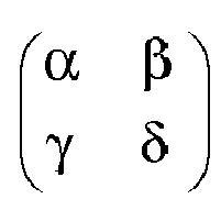

but it will not be identical to it. - Equations (2.a) and (2.b) can be grouped into a single equation, where the 4×4 matrix and the 4×1 vectors are shown in partitioned form.

- If Spatial Multiplexing, SM, is used in the two polarizations, we have

where (S 1,S 2) are two symbols transmitted by the first pair of antennas and (S 3,S 4) are the symbols transmitted by the second pair of antennas. - In the case Alamouti codes are used on the two polarizations, the code matrices are

- Therefore, we will have :


- When we use the matrix D given by (1), we have


- The first stage of receiver processing consists of multiplying the received signal

where θ is a correction phase angle whose value is swept for finding an optimum of a quality of anyone of the two receive first and second signals S1, S2. - In other words, the best value of the correction angle or parameter θis determined according to some criterion as to the quality of symbol vector S 1or S 2, as explained below.
Using such a rotation matrix is equivalent to projecting the first and second receive signals S1 S2 on a same reference axis 50, onfigure 1 , for defining a composite signal, the first and second receive signals S1, S2 belonging to third and fourth sets of receive signals, respectively, which are considered as orthogonal vectors. - The idea is that, since the matrix


where W'1 and W'2 denote rotated vector noise terms. - Since each term in the matrix equation above is a 2×2 matrix itself, there exists no value of parameter θ which can perfectly cancel the interference between the two signals transmitted in orthogonal polarizations. Instead, we need to determine the value of the phase parameter θ which minimizes the interference between the two signals.
- As stated above,
figure 1 illustrates the detrimental fact that the tilt, by a phase angle θ, of the third andfourth polarization directions second polarization directions fourth antenna second polarization directions third polarization direction 3D on thefirst polarization direction 1D, and the same forpolarization directions - The value of parameter angle θ is swept in a continuous way, up or down, i.e. in the direction causing an increase of the quality. In an alternative way, parameter angle θ takes pseudo random values (sample values, for sampling the corresponding quality) in an angular range of values, in order to determine a best portion of said range and then an angular density of sample values is increased there, for locating an optimum position of the parameter angle θ leading to the optimum quality.
- Assume that we wish to estimate the symbol vector S 1 first.
- In that case, the phase angle θ must be determined so as to maximize the quality, i.e. the useful signal magnitude ∥αH 1 Cosθ +γH 3 Sinθ∥ while minimizing the magnitude of the interference term∥βH 2 Cosθ + δH 4 Sinθ∥, where ∥.∥ denotes some suitable matrix norm. More precisely, the receiver computes the signal-to-interference ratio (SIR), or, better, the signal-to-noise-plus-interference-ratio (SNIR), for different values of the phase θ and determines the optimum value of this phase. For a given value of the phase θ, the SIR is given by:

- Similarly, the SNIR is given by:

where
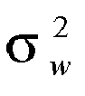
- Using the optimized phase parameter θ, the receiver makes an estimate of the symbol represented by the amended first symbol vector S 1, now better presented as the eigen vector X1.
- This estimate is done by using well-known receiver techniques for the space-time code used. The symbol estimation is carried out at each symbol period in SM and every two symbol periods in Alamouti's STC and in Matrix D. This estimation is thus made in the presence of some residual interference, because the receiver cannot completely eliminate the interference term in equation (4).
- Once an estimate of the first symbol vector S 1 is obtained, the interference of first symbol vector S 1 on second symbol vector S 2 is removed and the second symbol vector S 2 is estimated, in the same way, using well-known techniques for the space-time code at hand.
- In a preferred embodiment of the invention, the receiver makes one or more iterations. That is, after estimating the second symbol vector S 2, it cancels the interference of second symbol vector S 2 on first symbol vector S 1 and makes a new decision on first symbol vector S 1, and so forth.
- The process described above is also applicable to other dimensions. In a 2K×2K MIMO system where K is an arbitrary integer, the first K transmit antennas and K receive antennas form a K×K MIMO system in one polarization and other K transmit antennas and K receive antennas form a K×K MIMO system in the other polarization, and the interference between the two systems is cancelled at the receiver as described above for the 4×4 MIMO system.
- In a 2×2 MIMO system using this concept, the signals spatially multiplexed using the H and V polarizations are scalars (single input single output signals). In that particular case, the phase parameter θ involved in the first stage of the receiver can be computed to completely cancel interference of one signal on the other.
- As evidenced above, the method of the invention is carried out by circuits having specific features.
- Consequently, the transmit device or
station 100 includes acentral unit 110 receiving one or many incoming data streams to be transmitted by radio. Thecentral unit 110 includes atime basis 111 associated with aprogram memory 112 commanding aprocessing unit 113 which controls radio transmitcircuits 120. In a usual way, theprocessing unit 113 encodes an incoming data stream into symbol signals representing a batch of bits, and these symbol signals are transmitted to the transmitcircuits 120.Memory 112 controls all the steps for processing the transmit signals.Memory 112 can be of any kind of medium, for instance a RAM memory, a hard disk, and can be a mobile medium to be plug in a computer for running the process.Memory 112 can also be arranged for allowing the process program code instructions be downloaded through a data network. - Transmit
circuits 120 are arranged for applying said first and second pluralities of streams of symbol signals on a said first plurality and second plurality of transmitantennas antennas 131 having a samefirst polarization direction 1D and the second plurality of transmitantennas 132 having a samesecond polarization direction 2D orthogonal to saidfirst polarization direction 1D. - The receive
device 200 includes acentral unit 210 including atime basis 211 and aprogram memory 212 for controlling all the steps, listed below, for processing the receive signals.Memory 212 can be of any kind of medium, for instance a RAM memory, a hard disk, and can be a mobile medium to be plug in a computer for running the process.Memory 212 can also be arranged for allowing the process program code instructions be downloaded through a data network. - The
central unit 210 is fed by receivecircuits 220 which are arranged for receiving at least one of the streams of the first plurality and at least one of the streams of the second plurality, using together third and fourth pluralities of receiveantennas antennas 231 having the samethird polarization direction 3D and the fourth plurality of receiveantennas 232 having the samefourth polarization direction 4D orthogonal to saidthird polarization direction 3D, - In the
central unit 210, afirst processing circuit 213, for rotation computing, takes into consideration at least one pair of receive signals S1, S2 belonging to said third and fourth sets, respectively, it means that they are considered as orthogonal vectors Vrv, Vrh, and saidprocessing circuits 213 project said pair of signals on a same reference axis 50 for defining a composite signal. - A
quality circuit 214 receives the composite signal and determines an estimate of a quality of the composite signal, based on a predetermined quality criterion. - A
rotation circuit 215 causes the reference axis 50 to progressively rotate for determining a said correction angle θ, relating to a first (S 1) of said receive signals, corresponding to an optimum value of said quality provided by thequality circuit 214, and thus the composite signal is considered as being upgraded into a first eigen vector signal (X1) representing a first one of two related transmit signals. - A
second processing circuit 216, for selecting an optimal rotation, computes an interference component, of said first receive signal (S 1) on said second receive signal (S 2), based on said correction angle (θ), and it is subtracted from said second receive signal (S 2) for upgrading it into a second eigen vector signal (X2) representing a second one of the two related transmit signals. - In this example, the
second processing circuit 216 receives, in succession, each of the symbol signals processed by thefirst processing circuit 213 for each value of the correction angle θ, each symbol signal being labeled with a quality note provided by thequality circuit 214. If the values of the correction angle θ are swept in a progressive way, i.e. in an ordered way of increase or decrease, only the three last labeled symbol signals have to be stored for detecting if the second one is a maximum value versus the third and first ones. - In the above explanation, the magnitude of the final correction angle θ is equal to the tilt value, and the respective signs are opposite ones. Consequently, the tilt is cancelled by a subtractive correction.
- It should however be noted that, if the tilt is above 45 degrees, a slope of a curve representing the quality, when the correction angle θ is varied, would increase towards a value corresponding to a correction which would not cancel the tilt but which would add a positive correction for reaching 90 degrees. In such a condition, the roles of third and
fourth antennas - Consequently, in a general point of view, the correction brings the tilt to a value which is an integer of π/2.These circuits 210-216 also deal with the other, annex, features listed in the beginning of the specification.
- In the above description, the transmit
antennas antennas receiver 200 is dedicated to thetransmitter 100.
Further, the total number is odd and it is split into two equal numbers, each channel having a "twin", orthogonal, channel. - It must be noted that these statements are only for an optimum of efficiency in transmission.
- Firstly, the receiver could only receive some of the transmit streams, and it could also receive other streams from other transmitters. Consequently, the method according to the invention would be used for the streams of one transmitter, whereas the streams of any other transmitter could also be processed according to the invention. If the transmit antennas of the transmitters are mutually perfectly parallel or orthogonal, the result (phase parameter θ) obtained when processing the symbol signals received from one transmitter could be used for amending the symbol signals received from the other transmitter.
- Secondly, the number of antennas in the horizontal plane could differ from the number of antennas polarized in the vertical plane. In that case, the use of the transmission channel would not be optimal, since some streams would not be associated with a "twin".
Claims (13)
- A method for transmitting radio signals, including the following steps :for transmission, from a transmit device,a) first and second pluralities of streams of symbol signals are applied on a said first plurality and a said second plurality of transmit antennas, respectively, the first plurality of transmit antennas having a same first polarization and the second plurality of transmit antennas having a same second polarization orthogonal to said first polarization,for reception, in a receive device :b) at least one of the streams of the first plurality and at least one of the streams of the second plurality are received using together third and fourth pluralities of receive antennas providing third sets and fourth sets of receive signals (S1, S2), respectively, the third plurality of receive antennas having a same third polarization and the fourth plurality of receive antennas having a same fourth polarization orthogonal to said third polarization,c) at least one pair of receive signals (S1, S2) belonging to said third and fourth sets, respectively, are projected on a same reference axis for defining a composite signal,d) a quality of the composite signal is estimated based on a predetermined quality criterion,e) the reference axis is rotated for determining a correction angle (θ), relating to a first (S 1) of said receive signals, corresponding to an optimum value of said quality, for which an interference effect of an alignment mismatch between the transmit antennas and the respective receive antennas is at a minimum, wherein the composite signal is considered as being upgraded into a first eigen vector signal (X1) representing a first one of two related transmit signals, andf) in anyone of said devices, for canceling said interference effect, a correction action is carried out, based on said correction angle (θ).
- The method according to claim 1, wherein the correction action is carried out in the receive device, by computing an interference component, of said first receive signal (S 1) on said second receive signal (S 2), based on said correction angle, and subtracting said interference component from said second receive signal (S 2) for upgrading it into a second eigen vector signal (X2) representing a second one of the two related transmit signals.
- The method according to claim 2, wherein an interference component, of said second receive signal (S 2) on said first receive signal (S 1), is computed, based on said correction angle (θ), and is subtracted from said first eigen vector (X1) in order to improve it into a corrected first eigen vector.
- The method according to claim 3, wherein an improved interference component, of said corrected first eigen vector on said second receive signal (S 2), is computed, based on said correction angle (θ), and is subtracted from said second receive signal (S 2) for obtaining a corrected second eigen vector signal representing said second one of the two related transmit signals.
- The method according to anyone of claims 1 to 4, wherein the first plurality and the second plurality are of a same size.
- The method according to anyone of claims 1 to 5, wherein the third plurality and the fourth plurality are of a same size.
- The method according to anyone of claims 1 to 6, wherein the first plurality together with the second plurality are of a same size as the third plurality together with the fourth plurality.
- A communications system for transmitting radio signals according to anyone of claims 2 to 7, including :- a transmit device (100), including :. radio transmit circuits (120) arranged for transmitting first and second pluralities of streams of symbol signals to a said first plurality and said second plurality of transmit antennas (131, 132), respectively, the first plurality of transmit antennas (131) having a same first polarization and the second plurality of transmit antennas (132) having a same second polarization orthogonal to said first polarization,- at least one receive device (200), including :. third (231) and fourth (232) pluralities of receive antennas, for receiving at least one of the streams of the first plurality and at least one of the streams of the second plurality, respectively, and thus providing third sets and fourth sets of receive signals, respectively, the third plurality of receive antennas (231) having a same third polarization and the fourth plurality of receive antennas (232) having a same fourth polarization orthogonal to said third polarization,. a first processing circuit (213) for projecting at least one pair of receive signals (S1, S2), belonging to said third and fourth sets, respectively, on a same reference axis (50) for defining a composite signal,. a quality circuit (214) for receiving the composite signal and estimating a quality thereof, based on a predetermined quality criterion,. a rotation circuit (215) for rotating the reference axis (50) in order that the quality circuit (214) determines a correction angle (θ), relating to a first (S 1) of said receive signals, corresponding to an optimum value of said quality, for upgrading the composite signal into a first eigen vector signal (X1) representing a first one of two related transmit signals, and. a second processing circuit (216) for computing an interference component, of said first receive signal (S 1) on said second receive signal (S 2), based on said correction angle (θ), and for subtracting said interference component from said second receive signal (S 2) for upgrading it into a second eigen vector signal (X2) representing a second one of the two related transmit signals.
- A communications system according to claim 8, wherein the first plurality is of two first transmit antennas (131) and the second plurality is of two second transmit antennas (132).
- A receive device (200) for a communications system according to anyone of claims 8 and 9, including :. third (231) and fourth (232) pluralities of receive antennas, for receiving at least one of the streams of the first plurality and at least one of the streams of the second plurality, respectively, and thus providing third sets and fourth sets of receive signals, respectively, the third plurality of receive antennas (231) having a same third polarization and the fourth plurality of receive antennas (232) having a same fourth polarization orthogonal to said third polarization,. a first processing circuit (213) for projecting at least one pair of receive signals (S1, S2), belonging to said third and fourth sets, respectively, on a same reference axis (50) for defining a composite signal,. a quality circuit (214) for receiving the composite signal and estimating a quality thereof, based on a predetermined quality criterion,. a rotation circuit (215) for rotating the reference axis (50) in order that the quality circuit (214) determines a correction angle (θ), relating to a first (iS1) of said receive signals, corresponding to an optimum value of said quality, for upgrading the composite signal into a first eigen vector signal (X1) representing a first one of two related transmit signals, and. a second processing circuit (216) for computing an interference component, of said first receive signal (S 1) on said second receive signal (S 2), based on said correction angle (θ), and for subtracting said interference component from said second receive signal (S 2) for upgrading it into a second eigen vector signal (X2) representing a second one of the two related transmit signals.
- Using a communications system according to anyone of claims 8 and 9, wherein the receive device (200) is a mobile device.
- A computer program product which can be downloaded from a communications network and/or stored on a storage medium which can be read by a computer (210) and/or processed by a processor, characterized in that it contains program code instructions for the embodiment of the method according to anyone of claims 1 to 7, when said program is run on a computer.
- Storage means, which can be read by a computer, storing a set of instructions which can be run on said computer for embodying the method according to anyone of claims 1 to 7.
Priority Applications (2)
| Application Number | Priority Date | Filing Date | Title |
|---|---|---|---|
| EP08170266.4A EP2192696B1 (en) | 2008-11-28 | 2008-11-28 | Wireless communications method and system with spatial multiplexing using dually polarized antennas and corresponding receiver |
| US12/626,744 US8363745B2 (en) | 2008-11-28 | 2009-11-27 | Wireless communications method and system with spatial multiplexing using dually polarized antennas and corresponding receiver |
Applications Claiming Priority (1)
| Application Number | Priority Date | Filing Date | Title |
|---|---|---|---|
| EP08170266.4A EP2192696B1 (en) | 2008-11-28 | 2008-11-28 | Wireless communications method and system with spatial multiplexing using dually polarized antennas and corresponding receiver |
Publications (2)
| Publication Number | Publication Date |
|---|---|
| EP2192696A1 true EP2192696A1 (en) | 2010-06-02 |
| EP2192696B1 EP2192696B1 (en) | 2014-12-31 |
Family
ID=40551081
Family Applications (1)
| Application Number | Title | Priority Date | Filing Date |
|---|---|---|---|
| EP08170266.4A Not-in-force EP2192696B1 (en) | 2008-11-28 | 2008-11-28 | Wireless communications method and system with spatial multiplexing using dually polarized antennas and corresponding receiver |
Country Status (2)
| Country | Link |
|---|---|
| US (1) | US8363745B2 (en) |
| EP (1) | EP2192696B1 (en) |
Families Citing this family (8)
| Publication number | Priority date | Publication date | Assignee | Title |
|---|---|---|---|---|
| EP2192696B1 (en) * | 2008-11-28 | 2014-12-31 | Sequans Communications | Wireless communications method and system with spatial multiplexing using dually polarized antennas and corresponding receiver |
| US10153824B2 (en) * | 2014-11-13 | 2018-12-11 | Hitachi, Ltd. | Wireless communication system and system using same |
| US10334515B2 (en) | 2017-01-13 | 2019-06-25 | ENK Wireless, Inc. | Conveying information via auxiliary device selection |
| JP6903450B2 (en) * | 2017-02-23 | 2021-07-14 | 株式会社Nttドコモ | User terminal and cell selection method |
| US10804998B2 (en) | 2018-05-07 | 2020-10-13 | ENK Wireless, Inc. | Systems/methods of providing increased wireless capacity, vehicular safety, electrical power wirelessly, and device control responsive to geographic position |
| US11100796B2 (en) | 2018-05-07 | 2021-08-24 | ENK Wireless, Inc. | Systems/methods of improving vehicular safety |
| US11075740B2 (en) | 2018-05-07 | 2021-07-27 | ENK Wireless, Inc. | Systems/methods of communications using a plurality of cooperative devices |
| US10681716B2 (en) * | 2018-05-07 | 2020-06-09 | ENK Wireless, Inc. | Systems/methods of providing increased wireless capacity, vehicular safety, electrical power wirelessly, and device control responsive to geographic position |
Citations (1)
| Publication number | Priority date | Publication date | Assignee | Title |
|---|---|---|---|---|
| US20080280571A1 (en) * | 2007-05-11 | 2008-11-13 | Broadcom Corporation, A California Corporation | RF transceiver with adjustable antenna assembly |
Family Cites Families (7)
| Publication number | Priority date | Publication date | Assignee | Title |
|---|---|---|---|---|
| US5724666A (en) * | 1994-03-24 | 1998-03-03 | Ericsson Inc. | Polarization diversity phased array cellular base station and associated methods |
| DE60332893D1 (en) * | 2002-04-25 | 2010-07-22 | Imec | CDMA Reception Transmission Techniques for Radio Systems with Multiple Inputs and Multiple Outputs (MIMO) |
| US8060132B2 (en) * | 2006-12-28 | 2011-11-15 | Samsung Electronics Co., Ltd | Apparatus and method for a repeater using a multi-antenna in a wireless communication system |
| US20090017910A1 (en) * | 2007-06-22 | 2009-01-15 | Broadcom Corporation | Position and motion tracking of an object |
| KR20080073624A (en) * | 2007-02-06 | 2008-08-11 | 삼성전자주식회사 | Codebook generation method and apparatus for multipolarized multiple input / output system |
| EP2192696B1 (en) * | 2008-11-28 | 2014-12-31 | Sequans Communications | Wireless communications method and system with spatial multiplexing using dually polarized antennas and corresponding receiver |
| US8085199B2 (en) * | 2008-12-13 | 2011-12-27 | Broadcom Corporation | Receiver including a matrix module to determine angular position |
-
2008
- 2008-11-28 EP EP08170266.4A patent/EP2192696B1/en not_active Not-in-force
-
2009
- 2009-11-27 US US12/626,744 patent/US8363745B2/en active Active
Patent Citations (1)
| Publication number | Priority date | Publication date | Assignee | Title |
|---|---|---|---|---|
| US20080280571A1 (en) * | 2007-05-11 | 2008-11-13 | Broadcom Corporation, A California Corporation | RF transceiver with adjustable antenna assembly |
Non-Patent Citations (2)
| Title |
|---|
| J.-C. BELFIORE; G. REKAYA; E. VITERBO: "The Golden Code: A 2x2 Full-Rate Space--Time Code with Nonvanishing Determinants", IEEE TRANSACTIONS ON INFORMATION THEORY, vol. 51, no. 4, April 2005 (2005-04-01), pages 1432 - 1436, XP011129052, DOI: doi:10.1109/TIT.2005.844069 |
| S. M. ALAMOUTI: "A Simple Transmit Diversity Technique for Wireless Communications", IEEE JOURNAL ON SELECTED AREAS IN COMMUNICATIONS, vol. 16, no. 8, October 1998 (1998-10-01), pages 1451 - 1458, XP002100058, DOI: doi:10.1109/49.730453 |
Also Published As
| Publication number | Publication date |
|---|---|
| EP2192696B1 (en) | 2014-12-31 |
| US8363745B2 (en) | 2013-01-29 |
| US20100135445A1 (en) | 2010-06-03 |
Similar Documents
| Publication | Publication Date | Title |
|---|---|---|
| EP2192696B1 (en) | Wireless communications method and system with spatial multiplexing using dually polarized antennas and corresponding receiver | |
| Joung | Space–time line code | |
| CN101675599B (en) | Codebook generation method and device for generating a codebook for a multi-polarized multiple-input multiple-output system | |
| US8238917B2 (en) | Method and system for utilizing tone grouping with Givens rotations to reduce overhead associated with explicit feedback information | |
| US8233552B2 (en) | Method and system for utilizing givens rotation expressions for asymmetric beamforming matrices in explicit feedback information | |
| US7356090B2 (en) | Transmission/reception apparatus for a wireless communication system with three transmission antennas | |
| US20040002364A1 (en) | Transmitting and receiving methods | |
| US20030026349A1 (en) | Multiple space time transmit diversity communication system with selected complex conjugate inputs | |
| US8170132B2 (en) | Method and apparatus for transmitting signals in a multiple antennas system | |
| US20130301749A1 (en) | Precoding Matrix Index Selection Process for a MIMO Receiver Based on a Near-ML Detection, and Apparatus for Doing the Same | |
| Younis et al. | Generalised spatial modulation for large-scale MIMO | |
| US20130225089A1 (en) | Radio communication apparatus, system, and method | |
| US7839810B2 (en) | Transmitter, communication system and communication method | |
| US8477663B2 (en) | Multiple input multiple output communication system and communication method of configuring codebook | |
| EP3100371B1 (en) | Method and system for providing diversity in polarization of antennas | |
| Aparna et al. | Channel modeling and estimation of polarized mimo for land mobile satellite systems | |
| JP2005176325A (en) | Method for increasing transmit diversity gain in wireless communication system, and wireless communication system | |
| Debels et al. | SNR maximization and modulo loss reduction for Tomlinson-Harashima precoding | |
| Tunalı et al. | Comparing Type I and Type II Codebooks in 5G MIMO with Imperfect CSI at the Receiver | |
| US20070082624A1 (en) | System and method for transmitting/receiving signal in mobile communication system using multiple input multiple output scheme | |
| US20250279806A1 (en) | Devices and methods for efficient joint transmission in a wireless network | |
| Childress | Physical Layer Security for Mimo Wireless Systems | |
| Zhang et al. | Symbol Timing Recovery and Performance Analysis in Satellite LoS-MIMO With Non-Homologous Receiver | |
| Yang | A family of space-time block codes for wireless communications | |
| Krivochiza et al. | Optimally Conditioned Channel Matrices in Precoding Enabled Non-Terrestrial Networks |
Legal Events
| Date | Code | Title | Description |
|---|---|---|---|
| PUAI | Public reference made under article 153(3) epc to a published international application that has entered the european phase |
Free format text: ORIGINAL CODE: 0009012 |
|
| AK | Designated contracting states |
Kind code of ref document: A1 Designated state(s): AT BE BG CH CY CZ DE DK EE ES FI FR GB GR HR HU IE IS IT LI LT LU LV MC MT NL NO PL PT RO SE SI SK TR |
|
| AX | Request for extension of the european patent |
Extension state: AL BA MK RS |
|
| 17P | Request for examination filed |
Effective date: 20101119 |
|
| AKX | Designation fees paid |
Designated state(s): AT BE BG CH CY CZ DE DK EE ES FI FR GB GR HR HU IE IS IT LI LT LU LV MC MT NL NO PL PT RO SE SI SK TR |
|
| 17Q | First examination report despatched |
Effective date: 20110120 |
|
| GRAP | Despatch of communication of intention to grant a patent |
Free format text: ORIGINAL CODE: EPIDOSNIGR1 |
|
| INTG | Intention to grant announced |
Effective date: 20140624 |
|
| GRAS | Grant fee paid |
Free format text: ORIGINAL CODE: EPIDOSNIGR3 |
|
| RAP1 | Party data changed (applicant data changed or rights of an application transferred) |
Owner name: SEQUANS COMMUNICATIONS |
|
| GRAA | (expected) grant |
Free format text: ORIGINAL CODE: 0009210 |
|
| AK | Designated contracting states |
Kind code of ref document: B1 Designated state(s): AT BE BG CH CY CZ DE DK EE ES FI FR GB GR HR HU IE IS IT LI LT LU LV MC MT NL NO PL PT RO SE SI SK TR |
|
| REG | Reference to a national code |
Ref country code: CH Ref legal event code: EP Ref country code: GB Ref legal event code: FG4D |
|
| REG | Reference to a national code |
Ref country code: IE Ref legal event code: FG4D |
|
| REG | Reference to a national code |
Ref country code: AT Ref legal event code: REF Ref document number: 704912 Country of ref document: AT Kind code of ref document: T Effective date: 20150215 |
|
| REG | Reference to a national code |
Ref country code: DE Ref legal event code: R096 Ref document number: 602008036096 Country of ref document: DE Effective date: 20150226 |
|
| PG25 | Lapsed in a contracting state [announced via postgrant information from national office to epo] |
Ref country code: NO Free format text: LAPSE BECAUSE OF FAILURE TO SUBMIT A TRANSLATION OF THE DESCRIPTION OR TO PAY THE FEE WITHIN THE PRESCRIBED TIME-LIMIT Effective date: 20150331 Ref country code: FI Free format text: LAPSE BECAUSE OF FAILURE TO SUBMIT A TRANSLATION OF THE DESCRIPTION OR TO PAY THE FEE WITHIN THE PRESCRIBED TIME-LIMIT Effective date: 20141231 Ref country code: LT Free format text: LAPSE BECAUSE OF FAILURE TO SUBMIT A TRANSLATION OF THE DESCRIPTION OR TO PAY THE FEE WITHIN THE PRESCRIBED TIME-LIMIT Effective date: 20141231 |
|
| REG | Reference to a national code |
Ref country code: NL Ref legal event code: VDEP Effective date: 20141231 |
|
| REG | Reference to a national code |
Ref country code: LT Ref legal event code: MG4D |
|
| PG25 | Lapsed in a contracting state [announced via postgrant information from national office to epo] |
Ref country code: SE Free format text: LAPSE BECAUSE OF FAILURE TO SUBMIT A TRANSLATION OF THE DESCRIPTION OR TO PAY THE FEE WITHIN THE PRESCRIBED TIME-LIMIT Effective date: 20141231 Ref country code: GR Free format text: LAPSE BECAUSE OF FAILURE TO SUBMIT A TRANSLATION OF THE DESCRIPTION OR TO PAY THE FEE WITHIN THE PRESCRIBED TIME-LIMIT Effective date: 20150401 Ref country code: LV Free format text: LAPSE BECAUSE OF FAILURE TO SUBMIT A TRANSLATION OF THE DESCRIPTION OR TO PAY THE FEE WITHIN THE PRESCRIBED TIME-LIMIT Effective date: 20141231 Ref country code: HR Free format text: LAPSE BECAUSE OF FAILURE TO SUBMIT A TRANSLATION OF THE DESCRIPTION OR TO PAY THE FEE WITHIN THE PRESCRIBED TIME-LIMIT Effective date: 20141231 |
|
| REG | Reference to a national code |
Ref country code: AT Ref legal event code: MK05 Ref document number: 704912 Country of ref document: AT Kind code of ref document: T Effective date: 20141231 |
|
| PG25 | Lapsed in a contracting state [announced via postgrant information from national office to epo] |
Ref country code: NL Free format text: LAPSE BECAUSE OF FAILURE TO SUBMIT A TRANSLATION OF THE DESCRIPTION OR TO PAY THE FEE WITHIN THE PRESCRIBED TIME-LIMIT Effective date: 20141231 |
|
| PG25 | Lapsed in a contracting state [announced via postgrant information from national office to epo] |
Ref country code: ES Free format text: LAPSE BECAUSE OF FAILURE TO SUBMIT A TRANSLATION OF THE DESCRIPTION OR TO PAY THE FEE WITHIN THE PRESCRIBED TIME-LIMIT Effective date: 20141231 Ref country code: SK Free format text: LAPSE BECAUSE OF FAILURE TO SUBMIT A TRANSLATION OF THE DESCRIPTION OR TO PAY THE FEE WITHIN THE PRESCRIBED TIME-LIMIT Effective date: 20141231 Ref country code: CZ Free format text: LAPSE BECAUSE OF FAILURE TO SUBMIT A TRANSLATION OF THE DESCRIPTION OR TO PAY THE FEE WITHIN THE PRESCRIBED TIME-LIMIT Effective date: 20141231 Ref country code: RO Free format text: LAPSE BECAUSE OF FAILURE TO SUBMIT A TRANSLATION OF THE DESCRIPTION OR TO PAY THE FEE WITHIN THE PRESCRIBED TIME-LIMIT Effective date: 20141231 |
|
| PG25 | Lapsed in a contracting state [announced via postgrant information from national office to epo] |
Ref country code: IS Free format text: LAPSE BECAUSE OF FAILURE TO SUBMIT A TRANSLATION OF THE DESCRIPTION OR TO PAY THE FEE WITHIN THE PRESCRIBED TIME-LIMIT Effective date: 20150430 Ref country code: PL Free format text: LAPSE BECAUSE OF FAILURE TO SUBMIT A TRANSLATION OF THE DESCRIPTION OR TO PAY THE FEE WITHIN THE PRESCRIBED TIME-LIMIT Effective date: 20141231 Ref country code: AT Free format text: LAPSE BECAUSE OF FAILURE TO SUBMIT A TRANSLATION OF THE DESCRIPTION OR TO PAY THE FEE WITHIN THE PRESCRIBED TIME-LIMIT Effective date: 20141231 |
|
| REG | Reference to a national code |
Ref country code: DE Ref legal event code: R097 Ref document number: 602008036096 Country of ref document: DE |
|
| PG25 | Lapsed in a contracting state [announced via postgrant information from national office to epo] |
Ref country code: EE Free format text: LAPSE BECAUSE OF FAILURE TO SUBMIT A TRANSLATION OF THE DESCRIPTION OR TO PAY THE FEE WITHIN THE PRESCRIBED TIME-LIMIT Effective date: 20141231 Ref country code: DK Free format text: LAPSE BECAUSE OF FAILURE TO SUBMIT A TRANSLATION OF THE DESCRIPTION OR TO PAY THE FEE WITHIN THE PRESCRIBED TIME-LIMIT Effective date: 20141231 |
|
| PLBE | No opposition filed within time limit |
Free format text: ORIGINAL CODE: 0009261 |
|
| STAA | Information on the status of an ep patent application or granted ep patent |
Free format text: STATUS: NO OPPOSITION FILED WITHIN TIME LIMIT |
|
| REG | Reference to a national code |
Ref country code: FR Ref legal event code: PLFP Year of fee payment: 8 |
|
| 26N | No opposition filed |
Effective date: 20151001 |
|
| PG25 | Lapsed in a contracting state [announced via postgrant information from national office to epo] |
Ref country code: IT Free format text: LAPSE BECAUSE OF FAILURE TO SUBMIT A TRANSLATION OF THE DESCRIPTION OR TO PAY THE FEE WITHIN THE PRESCRIBED TIME-LIMIT Effective date: 20141231 |
|
| PG25 | Lapsed in a contracting state [announced via postgrant information from national office to epo] |
Ref country code: SI Free format text: LAPSE BECAUSE OF FAILURE TO SUBMIT A TRANSLATION OF THE DESCRIPTION OR TO PAY THE FEE WITHIN THE PRESCRIBED TIME-LIMIT Effective date: 20141231 |
|
| PG25 | Lapsed in a contracting state [announced via postgrant information from national office to epo] |
Ref country code: BE Free format text: LAPSE BECAUSE OF FAILURE TO SUBMIT A TRANSLATION OF THE DESCRIPTION OR TO PAY THE FEE WITHIN THE PRESCRIBED TIME-LIMIT Effective date: 20141231 |
|
| PG25 | Lapsed in a contracting state [announced via postgrant information from national office to epo] |
Ref country code: LU Free format text: LAPSE BECAUSE OF FAILURE TO SUBMIT A TRANSLATION OF THE DESCRIPTION OR TO PAY THE FEE WITHIN THE PRESCRIBED TIME-LIMIT Effective date: 20151128 Ref country code: MC Free format text: LAPSE BECAUSE OF FAILURE TO SUBMIT A TRANSLATION OF THE DESCRIPTION OR TO PAY THE FEE WITHIN THE PRESCRIBED TIME-LIMIT Effective date: 20141231 |
|
| REG | Reference to a national code |
Ref country code: CH Ref legal event code: PL |
|
| PG25 | Lapsed in a contracting state [announced via postgrant information from national office to epo] |
Ref country code: CH Free format text: LAPSE BECAUSE OF NON-PAYMENT OF DUE FEES Effective date: 20151130 Ref country code: LI Free format text: LAPSE BECAUSE OF NON-PAYMENT OF DUE FEES Effective date: 20151130 |
|
| REG | Reference to a national code |
Ref country code: IE Ref legal event code: MM4A |
|
| PG25 | Lapsed in a contracting state [announced via postgrant information from national office to epo] |
Ref country code: IE Free format text: LAPSE BECAUSE OF NON-PAYMENT OF DUE FEES Effective date: 20151128 |
|
| REG | Reference to a national code |
Ref country code: FR Ref legal event code: PLFP Year of fee payment: 9 |
|
| PGFP | Annual fee paid to national office [announced via postgrant information from national office to epo] |
Ref country code: DE Payment date: 20161118 Year of fee payment: 9 Ref country code: FR Payment date: 20161125 Year of fee payment: 9 Ref country code: GB Payment date: 20161026 Year of fee payment: 9 |
|
| PG25 | Lapsed in a contracting state [announced via postgrant information from national office to epo] |
Ref country code: HU Free format text: LAPSE BECAUSE OF FAILURE TO SUBMIT A TRANSLATION OF THE DESCRIPTION OR TO PAY THE FEE WITHIN THE PRESCRIBED TIME-LIMIT; INVALID AB INITIO Effective date: 20081128 Ref country code: BG Free format text: LAPSE BECAUSE OF FAILURE TO SUBMIT A TRANSLATION OF THE DESCRIPTION OR TO PAY THE FEE WITHIN THE PRESCRIBED TIME-LIMIT Effective date: 20141231 |
|
| PG25 | Lapsed in a contracting state [announced via postgrant information from national office to epo] |
Ref country code: CY Free format text: LAPSE BECAUSE OF FAILURE TO SUBMIT A TRANSLATION OF THE DESCRIPTION OR TO PAY THE FEE WITHIN THE PRESCRIBED TIME-LIMIT Effective date: 20141231 |
|
| PG25 | Lapsed in a contracting state [announced via postgrant information from national office to epo] |
Ref country code: TR Free format text: LAPSE BECAUSE OF FAILURE TO SUBMIT A TRANSLATION OF THE DESCRIPTION OR TO PAY THE FEE WITHIN THE PRESCRIBED TIME-LIMIT Effective date: 20141231 Ref country code: MT Free format text: LAPSE BECAUSE OF FAILURE TO SUBMIT A TRANSLATION OF THE DESCRIPTION OR TO PAY THE FEE WITHIN THE PRESCRIBED TIME-LIMIT Effective date: 20141231 |
|
| REG | Reference to a national code |
Ref country code: DE Ref legal event code: R119 Ref document number: 602008036096 Country of ref document: DE |
|
| GBPC | Gb: european patent ceased through non-payment of renewal fee |
Effective date: 20171128 |
|
| PG25 | Lapsed in a contracting state [announced via postgrant information from national office to epo] |
Ref country code: PT Free format text: LAPSE BECAUSE OF FAILURE TO SUBMIT A TRANSLATION OF THE DESCRIPTION OR TO PAY THE FEE WITHIN THE PRESCRIBED TIME-LIMIT Effective date: 20141231 |
|
| REG | Reference to a national code |
Ref country code: FR Ref legal event code: ST Effective date: 20180731 |
|
| PG25 | Lapsed in a contracting state [announced via postgrant information from national office to epo] |
Ref country code: DE Free format text: LAPSE BECAUSE OF NON-PAYMENT OF DUE FEES Effective date: 20180602 Ref country code: FR Free format text: LAPSE BECAUSE OF NON-PAYMENT OF DUE FEES Effective date: 20171130 |
|
| PG25 | Lapsed in a contracting state [announced via postgrant information from national office to epo] |
Ref country code: GB Free format text: LAPSE BECAUSE OF NON-PAYMENT OF DUE FEES Effective date: 20171128 |