EP2192464A2 - Monitoring system with dynamically configurable non-interfering signal processing - Google Patents
Monitoring system with dynamically configurable non-interfering signal processing Download PDFInfo
- Publication number
- EP2192464A2 EP2192464A2 EP09175690.8A EP09175690A EP2192464A2 EP 2192464 A2 EP2192464 A2 EP 2192464A2 EP 09175690 A EP09175690 A EP 09175690A EP 2192464 A2 EP2192464 A2 EP 2192464A2
- Authority
- EP
- European Patent Office
- Prior art keywords
- machine
- signal processing
- waveforms
- management
- processing blocks
- Prior art date
- Legal status (The legal status is an assumption and is not a legal conclusion. Google has not performed a legal analysis and makes no representation as to the accuracy of the status listed.)
- Ceased
Links
- 238000012545 processing Methods 0.000 title claims abstract description 168
- 238000012544 monitoring process Methods 0.000 title claims abstract description 50
- 230000002452 interceptive effect Effects 0.000 title claims abstract description 13
- 238000005259 measurement Methods 0.000 claims description 84
- 238000000034 method Methods 0.000 claims description 15
- 238000013507 mapping Methods 0.000 claims description 3
- 230000000007 visual effect Effects 0.000 claims description 3
- 230000001360 synchronised effect Effects 0.000 description 9
- 230000006870 function Effects 0.000 description 5
- 230000004075 alteration Effects 0.000 description 4
- 238000013459 approach Methods 0.000 description 4
- 230000008859 change Effects 0.000 description 4
- 238000004891 communication Methods 0.000 description 4
- 238000001914 filtration Methods 0.000 description 4
- 238000004519 manufacturing process Methods 0.000 description 3
- 230000003287 optical effect Effects 0.000 description 3
- 238000007405 data analysis Methods 0.000 description 2
- 230000000694 effects Effects 0.000 description 2
- 238000012986 modification Methods 0.000 description 2
- 230000004048 modification Effects 0.000 description 2
- 230000008569 process Effects 0.000 description 2
- 239000004065 semiconductor Substances 0.000 description 2
- 230000003068 static effect Effects 0.000 description 2
- 238000004458 analytical method Methods 0.000 description 1
- 238000006243 chemical reaction Methods 0.000 description 1
- 239000002131 composite material Substances 0.000 description 1
- 238000004590 computer program Methods 0.000 description 1
- 238000001514 detection method Methods 0.000 description 1
- 230000007613 environmental effect Effects 0.000 description 1
- 239000000835 fiber Substances 0.000 description 1
- 230000036541 health Effects 0.000 description 1
- 239000000463 material Substances 0.000 description 1
- 238000010248 power generation Methods 0.000 description 1
- 230000008439 repair process Effects 0.000 description 1
- 238000005070 sampling Methods 0.000 description 1
- 239000007787 solid Substances 0.000 description 1
Images


Classifications
-
- G—PHYSICS
- G05—CONTROLLING; REGULATING
- G05B—CONTROL OR REGULATING SYSTEMS IN GENERAL; FUNCTIONAL ELEMENTS OF SUCH SYSTEMS; MONITORING OR TESTING ARRANGEMENTS FOR SUCH SYSTEMS OR ELEMENTS
- G05B23/00—Testing or monitoring of control systems or parts thereof
- G05B23/02—Electric testing or monitoring
- G05B23/0205—Electric testing or monitoring by means of a monitoring system capable of detecting and responding to faults
- G05B23/0208—Electric testing or monitoring by means of a monitoring system capable of detecting and responding to faults characterized by the configuration of the monitoring system
- G05B23/0213—Modular or universal configuration of the monitoring system, e.g. monitoring system having modules that may be combined to build monitoring program; monitoring system that can be applied to legacy systems; adaptable monitoring system; using different communication protocols
-
- G—PHYSICS
- G05—CONTROLLING; REGULATING
- G05B—CONTROL OR REGULATING SYSTEMS IN GENERAL; FUNCTIONAL ELEMENTS OF SUCH SYSTEMS; MONITORING OR TESTING ARRANGEMENTS FOR SUCH SYSTEMS OR ELEMENTS
- G05B23/00—Testing or monitoring of control systems or parts thereof
- G05B23/02—Electric testing or monitoring
- G05B23/0205—Electric testing or monitoring by means of a monitoring system capable of detecting and responding to faults
- G05B23/0218—Electric testing or monitoring by means of a monitoring system capable of detecting and responding to faults characterised by the fault detection method dealing with either existing or incipient faults
- G05B23/0221—Preprocessing measurements, e.g. data collection rate adjustment; Standardization of measurements; Time series or signal analysis, e.g. frequency analysis or wavelets; Trustworthiness of measurements; Indexes therefor; Measurements using easily measured parameters to estimate parameters difficult to measure; Virtual sensor creation; De-noising; Sensor fusion; Unconventional preprocessing inherently present in specific fault detection methods like PCA-based methods
-
- G—PHYSICS
- G05—CONTROLLING; REGULATING
- G05B—CONTROL OR REGULATING SYSTEMS IN GENERAL; FUNCTIONAL ELEMENTS OF SUCH SYSTEMS; MONITORING OR TESTING ARRANGEMENTS FOR SUCH SYSTEMS OR ELEMENTS
- G05B2219/00—Program-control systems
- G05B2219/30—Nc systems
- G05B2219/37—Measurements
- G05B2219/37493—Use of different frequency band pass filters to separate different signals
-
- G—PHYSICS
- G05—CONTROLLING; REGULATING
- G05B—CONTROL OR REGULATING SYSTEMS IN GENERAL; FUNCTIONAL ELEMENTS OF SUCH SYSTEMS; MONITORING OR TESTING ARRANGEMENTS FOR SUCH SYSTEMS OR ELEMENTS
- G05B2219/00—Program-control systems
- G05B2219/30—Nc systems
- G05B2219/37—Measurements
- G05B2219/37511—Select and process only those detected signals needed for a certain purpose
Definitions
- the present invention relates generally to monitoring machines and more particularly to using a dynamic signal processing configuration to monitor measurements associated with the management of a machine and measurements associated with the safety protection.
- monitored machine components may generate various signals representative of dynamic machine conditions.
- Signal-generating components such as sensors and transducers are typically positioned on or otherwise closely associated with points of interest of the machine.
- a portion of these signals and a subset of data analysis that is performed on these signals are used to determine safety critical machine performance. Actions taken on this data may include machine shut-down or a change in operating conditions of the machine that are necessary to prevent catastrophic loss of life, environmental damage, or financial loss.
- Another portion of these signals and subset of data analysis are used to manage the use of the machine. For example, this information may be used to schedule machine repair outages or to alter machine operating conditions to maximize performance, efficiency, or machine life.
- Alterations may include changing the sample rates and filtering to add or remove frequency content, changing the frequency that data samples are collected, or changing whether the data is integrated or not.
- An alteration could also arise if an operator of the machine needs to add a measurement or dynamic waveform display to further analyze the health of the machine.
- data associated with the safety protection of the machine are typically based on machine physical parameters such as bearing clearances, and are changed infrequently.
- availability and reliability are of utmost importance.
- the control over these different data sets may reside with different individuals within the plant. For example, measurements associated with the safety protection of the machine may be the responsibility of the plant operations, whereas the data associated with the management of the use of the machine may be the responsibility of the plant reliability group.
- the operations group needs confidence that the reliability group cannot impact production and the reliability group needs confidence that their actions will not impact production.
- one approach is to provide separate signal processing hardware devices with one hardware device assigned to processing data associated with the safety protection measurements and a second hardware device that processes data associated with management of the machine.
- This approach adds significant complexity and cost as measurements needed for protection and management must be produced in both hardware devices or else communicated between the two devices.
- only a limited amount of management data derived from the protection data is used. For example, if the protection data is generated from a Fast Fourier Transform, then a user of the management data may have access to the complete transform and the raw data feeding into the transform. However, the management data user cannot add more waveforms or significantly alter the data sampling without affecting the protection measurements.
- a system for monitoring a machine comprising at least one sensor located about the machine that generates signals representative of a machine condition.
- a monitoring module monitors the signals generated from the at least one sensor.
- the monitoring module comprises a first level signal processing component that generates a plurality of waveforms from the signals generated from the at least one sensor. Each of the plurality of waveforms provides different frequency information of the signals.
- a second level signal processing component that comprises a plurality of signal processing blocks that are dynamically configurable to be linked to form at least one data path that defines a signal processing operation to be performed on at least one waveform selected from the plurality of waveforms generated from the first level signal processing component to determine at least one measurement relating to the management of the operation of the machine and at least one data path that defines a signal processing operation to be performed on at least one waveform selected from the plurality of waveforms generated from the first level signal processing component to determine at least one measurement relating to the safety protection of the machine.
- Configurability of measurements relating to the management of the operation of the machine is independent and non-interfering with configurability of measurements relating to the safety protection of the machine.
- a method for monitoring a machine comprises: obtaining raw data representative of a condition occurring at a machine; generating a plurality of waveforms from the raw data, wherein each of the plurality of waveforms depict a visual representation having different frequency information of the raw data; and dynamically configuring a plurality of signal processing blocks to be linked to form at least one data path that defines a signal processing operation to be performed on at least one waveform selected from the plurality of waveforms to determine at least one measurement relating to the management of the operation of the machine and at least one measurement relating to the safety protection of the machine, without interfering with signal processing blocks used in other data paths that determine measurements relating to the management of the operation of the machine and other data paths that determine measurements relating to the safety protection of the machine.
- a tangible-readable medium that stores instructions, which when executed, enables a processor to monitor a machine.
- the instructions causes the processor to perform actions that comprises: obtaining signals representative of a machine condition; generating a plurality of waveforms from the signals, wherein each of the plurality of waveforms provides different frequency information of the signals; and dynamically configuring a plurality of signal processing blocks to be linked to form at least one data path that defines a signal processing operation to be performed on at least one waveform selected from the plurality of waveforms to determine at least one measurement relating to the management of the operation of the machine and at least one measurement relating to the safety protection of the machine, without interfering with signal processing blocks used in other data paths that determine measurements relating to the management of the operation of the machine and other data paths that determine measurements relating to the safety protection of the machine.
- At least one embodiment of the present invention is described below in reference to its application in connection with and operation of monitoring data generated from an industrial machine system.
- a non-exhaustive listing of possible industrial machine systems that are suitable for use with embodiments of the present invention include rotary machines, reciprocating machines and machine systems that are fixed.
- various aspects of the present invention are likewise applicable to any machinery of varying complexity where there is a need to monitor operation of data generated therefrom, such as for example, machines employed in assembly lines, production equipment, material handling equipment, and power generation equipment.
- a non-exhaustive listing of data that may be monitored from the above-noted machines includes vibration, temperature, pressure and other high-speed events that may occur with the machines.
- FIG. 1 is a schematic illustration of a monitoring system 100 that monitors a machine 105 according to one embodiment of the present invention.
- the monitoring system 100 includes a plurality of sensors 110 located about machine 105.
- Sensors 110 may include any type of sensor or transducer that may acquire dynamic data that pertains to the condition of machine 105 such as an accelerometer, temperature sensor and pressure sensor that sense for vibration, temperature and pressure, respectively.
- FIG. 1 shows sensors 110 attached to machine 105 in a wired configuration, those skilled in the art will recognize that sensors 110 can acquire dynamic data from machine 105 by wireless, electromagnetic or fiber optic modalities.
- the dynamic data acquired by sensors 110 is generally raw data obtained in analog signal form over a very large bandwidth that contains large quantities of information pertaining to machine 105 that can be extracted to provide information with respect to the operation and protection of machine 105.
- each sensor 110 After sensing and acquiring the dynamic data in analog signal form, each sensor 110 transmits analog signals containing the dynamic data to monitoring module 120 and to a respective analog-to-digital (A/D) converter 115 that converts the signals generated from the at least one sensor to sampled digital signals.
- A/D converters 115 may take the form of hardware devices, software, or a combination of hardware and software that are configured to perform the analog-to-digital signal conversion.
- a first level signal processing component 125 within monitoring module 120 receives the sampled digital signals from A/D converters 115 and monitors the signals generated from sensors 110 to manage data associated with the operation of machine 105 and data associated with the safety protection of machine 105.
- First level signal processing component 125 generates a plurality of waveforms from the signals generated from sensors 110 that have been digitized by A/D converters 115. Each of the plurality of waveforms provides different frequency information of the signals generated by sensors 110.
- first level signal processing component 125 uses dynamic waveform decimation and filtering and sample rate synchronization to an external timing signal to generate a multitude of waveforms having different sample rates and frequency spans from the dynamic data generated from sensors 110.
- First level signal processing component 125 may also perform signal diagnostics such as linear range checks, signal slew rate checks, or bias voltage checks.
- First level signal processing component 125 may be one of a number of programmable devices that may be programmed to perform functions such as dynamic waveform decimation and filtering and sample rate synchronization to an external timing signal.
- first level signal processing component 125 may be a programmable device selected from the group consisting of a field programmable gate array (FPGA), a programmable logic device (PLD), a complex programmable logic device (CPLD), an application specific integrated circuit (ASIC) and a processor.
- FPGA field programmable gate array
- PLD programmable logic device
- CPLD complex programmable logic device
- ASIC application specific integrated circuit
- monitoring module 120 further includes a second level signal processing component 130 that performs signal processing operations on any number of waveforms generated from first level signal processing component 125.
- These signal processing operations generally result in measurements that relate to the management of the operation of machine 105 and measurements that relate to the safety protection of the machine.
- second level signal processing component 130 comprises a plurality of signal processing blocks that are dynamically configurable to be linked to form at least one data path that defines a signal processing operation to be performed on at least one waveform selected from the plurality of waveforms generated from first level signal processing component 125.
- second level signal processing component 130 is configured to map the selected waveform(s) from the waveforms generated from first level signal processing component 125 to selected signal processing blocks that define the at least one data path.
- Each data path comprised of these signal processing blocks results in at least one measurement that may relate to the management of the operation of machine 105 and/or to the safety protection of machine 105.
- These signal processing blocks are dynamically configured because the blocks can be modifiable such that changes made to signal processing blocks in one data path do not interfere with signal processing blocks used in other data paths. Examples of changes include adding signal processing blocks to a data path, deleting signal processing blocks from a data path and altering signal processing blocks in a data path to generate another type of measurement.
- second level signal processing component 130 comprises a processor such as a signal processor or a microprocessor that is configured to execute the dynamically configured signal processing blocks.
- monitoring module 120 includes memory 135 which is configured to store measurements in predefined memory locations as allocated by a database (dB) manager 140. These measurements relate to the management of the operation of machine 105 and the safety protection of machine 105.
- memory 135 stores the waveforms generated from first level signal processing component 125, the dynamically configurable plurality of signal processing blocks utilized by second level signal processing component 130 and the measurements that relate to the management of the operation of machine 105 and measurements that relate to the safety protection of the machine 105 as determined by second level signal processing component 130.
- memory 135 can store additional information such as rules for collecting dynamic data and transmitting measurements from monitoring module 120 for additional diagnostics.
- Monitoring system 100 as shown in FIG. 1 may include a controller 145 that is in signal communication with monitoring module 120 to make adjustments to machine 105 and transmit output data from monitoring module 120 to a computing unit 150 via a network 155.
- the signal communication between controller 145 and monitoring module 120 may be made via electrical, electromagnetic, or fiber-optical connection.
- Controller 145 may be any known control system such as a programmable logic controller (PLC) or a distributed control system (DCS). In one embodiment of operation, controller 145 uses the optimized setpoints included in output data generated from monitoring module 120 to make adjustments to machine 105.
- the signal communication between controller 145 and computing unit 150 via network 155 may be made via electrical, electromagnetic, or fiber-optical connection.
- monitoring system 100 functions as an independent safety system and can return machine 105 to a safe operating condition independently of controller 145.
- the computing unit 150 is also in communication with the network 155 via a wired or wireless electrical, electromagnetic, or fiber-optical connection.
- Computing unit 150 which may be any type of server or computer, is located remotely of the controller 145, monitoring module 120, sensors 110, and machine 105. Data can be both received by computing unit 150 from controller 145, and transmitted from the computing unit 150 to controller 145.
- computing unit 150 which may be transportable (e.g., a laptop), may be moved to the site of the monitoring module 120 and be directly connected with the monitoring module 120.
- computing unit 150 provides direct diagnostic and analysis capability to monitoring module 120 via this direct connection.
- information in memory 135 may be accessed by a user of computing unit 150 via this direct connection.
- FIG. 2 is a schematic illustration of first level signal processing component 125 depicted in monitoring module 120 of FIG. 1 according to one embodiment of the present invention.
- first level signal processing component 125 signal processes data from A/D converters 115 by performing operations that include dynamic waveform decimation filtering and sample rate synchronization to an external timing signal.
- the dynamic waveforms generated by the first level signal processing component 125 are processed simultaneously, synchronously, and in-phase across all channels.
- monitoring module 100 supports 12 channels.
- An A/D interface 200 receives the digital data from A/D converters 115 and provides it in parallel to an asynchronous waveform generator 205 and a synchronous waveform generator 210 for each respective channel.
- Asynchronous waveform generators 205 and synchronous waveform generators 210 create and synchronize waveforms from the dynamic data provided by channels 1-4.
- Synchronous waveform generators 210 are clocked to a phase reference signal provided by a phase reference processor 215. In one embodiment, the phase reference signal is related to the speed of machine 205. In another embodiment, multiple synchronous waveform generators 210 can be used to generate synchronous waveforms from different phase references for the same sensor signal 110.
- asynchronous waveform generators 205 generate waveforms without regard to the phase reference signal, while synchronous waveform generators 210 generate waveforms that are in phase with the phase reference signal even through changing machine speed conditions. Note that asynchronous waveform generators 205 are still synchronized in time, maintain a constant sample rate and do not have an absolute phase reference.
- first level signal processing component 125 is capable of generating a multitude of sampled waveforms such that all of these waveforms are available simultaneously in different sampled rates. This feature allows these waveforms to be used with any of measurements associated with the management operation of machine 105 or safety protection of machine 105. For example, if a user of monitoring system 100 currently uses one synchronized waveform rate (e.g., 32x the speed of machine 105) for diagnosing problems associated with machine 105 but has an interest in using a different synchronized waveform rate (e.g., 128x) to diagnose the problem, then this configuration is able to provide this data to the user. Below are details on how this multitude of waveforms generated by first level signal processing component 125 can be added, deleted or modified for use by second level signal processing component 130 in obtaining measurements associated with the management operation of machine 105 or safety protection of machine 105.
- synchronized waveform rate e.g. 32x the speed of machine 105
- FIG. 3 is an example 300 of a plurality of dynamically configurable signal processing blocks linked together to form a data path that defines a signal processing operation to be performed according to one embodiment of the present invention.
- the dynamically configurable signal processing blocks include a processing block 305 that performs low pass filter processing, a processing block 310 that performs high pass filter processing, a processing block 315 that performs peak detection processing and a processing block 320 that performs low pass filter processing.
- a selected digital data stream (i.e., at least one waveform selected from the multitude of waveforms) is inputted to second level signal processing component 130 and fed into a data path that has been formed by the linkage of low pass filter processing block 305, high pass filter processing block 310, peak detector processing block 315 and low pass filter processing block 320. That is, a digital data stream output from first level signal processing component 125 is mapped to the input of the first signal processing block (i.e., low pass filter 305). The data moves from signal processing block to signal processing block by mapping the block outputs to the inputs of the next block. The output of the final processing block is then stored in a predefined memory location with memory 135 set by dB manager 140.
- this data path of linked signal processing blocks is representative of a particular measurement that is used for the safety protection of machine 105.
- each signal processing block generates values for a particular measurement, which is then used by the next subsequent signal processing block.
- each signal processing block can have multiple signal paths linked to it.
- this particular data path can be modified by a user of monitoring system 100 by adding another signal processing block to this path, deleting one of the signal processing blocks from the path and/or altering one of the signal processing blocks to generate a new output.
- This feature may be desirable to a user if for example the user wants to change the frequency span or sample rate.
- the user could dynamically configure this new data path by deleting a particular signal processing block from the data path and linking a new signal processing object that will pull the applicable waveform from the first level signal processing component 105 into this modified data path. This change can be made without interrupting the other signal processing blocks used in other signal paths that are employed by the second level signal processing component 130 to obtain measurements relating to the management operation and safety protection of the machine.
- This feature is quite advantageous in ensuring that data paths associated with the safety protection of machine 105 are not affected by changes made to signal processing blocks within data paths that relate to the management operation of machine 105 and vice versa. This feature is not possible in conventional machine condition monitoring systems because changes made to measurements related to the management operation of a machine will interfere with the measurements of the safety protection of the machine. Such interference would result in a shut down and resetting of the system to reconfigure such changes.
- the data path of linked signal processing blocks shown in FIG. 3 is only illustrative of one possible data path that could be utilized by second level signal processing component 130.
- second level signal processing component 130 would likely utilize a plurality of data paths having respective signal processing blocks to obtain measurements that relate to the management operation and safety protection of machine 105.
- Each of the signal processing blocks would be dynamically configurable to be linked such that any alterations made to the data paths would not interfere with other data paths utilized by second level signal processing component 130.
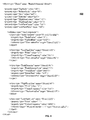
- FIG. 4 is an example of an Extensible Markup Language (XML) file 400 used to define the signal processing operation depicted in FIG. 3 .
- XML file 400 in this example describes how the signal processing blocks described in FIG. 3 are programmed to be configurably linked together such that the output of one block is fed into the next block.
- user configurable parameters can be changed for a given measurement regardless if the measurement relates to management operation or safety protection.
- the signal processing blocks are defined in metadata files in an XML format such that the signal processing block definitions may be changed without recompilation of the software. This architecture allows pre-defined measurements and custom designed and tested processing blocks to be added to monitoring module 120 without a software version change.
- the Direct2.LP filter object receives its input directly from data stream PhysicalChannel_1_1.
- This filter object has elements that define the filter corner and roll off.
- the output of each object has destination objects that perform further operations on the data. There may be multiple destinations for an object output.
- the data passes through a high pass filter object, followed by a peak detector and a low pass filter.
- the final result is a static variable.
- the static variable output can then be mapped for use in monitor rules or for output to controller 145 or computing unit 150.
- this XML file is stored in memory 135 and once downloaded by second level processing component 130, the file is activated. If a user decides to delete a signal processing block then that particular portion of the XML file is removed. For example, if a user did not want the high pass filter signal processing block, then the Direct2.HP filter object would be deleted from this measurement data path and then the peak detector signal processing block (Direct2.PK) would be linked to the low pass filter signal processing block (Direct2.LP2).
- Direct2.PK peak detector signal processing block
- DO2LP2 low pass filter signal processing block
- the effect on other objects can be controlled by only downloading the changed objects, object revision codes, comparison of objects against the current objects or other techniques that can determine when objects have been added, deleted or changed.
- monitoring module 120 can take the form of an entirely hardware embodiment, an entirely software embodiment or an embodiment containing both hardware and software elements.
- the processing functions performed by monitoring module 120 are implemented in software, which includes but is not limited to firmware, resident software, microcode, etc.
- monitoring module 120 can take the form of a computer program product accessible from a tangible-readable, computer-usable or computer-readable medium providing program code for use by or in connection with a processor, computer or any instruction execution system.
- a tangible-readable, computer-usable or computer readable medium can be any apparatus that can contain, store or communicate the program for use by or in connection with the processor, computer, instruction execution system, apparatus, or device.
- the tangible-readable, computer-usable or computer readable medium can be an electronic, magnetic, optical, electromagnetic, infrared, or semiconductor system (or apparatus or device).
- Examples of a computer-readable medium include a semiconductor or solid state memory, magnetic tape, a removable computer diskette, a random access memory (RAM), a read-only memory (ROM), a rigid magnetic disk and an optical disk.
- Current examples of optical disks include a compact disk - read only memory (CD-ROM), a compact disk - read/write (CD-R/W) and a digital video disc (DVD).
Landscapes
- Physics & Mathematics (AREA)
- General Physics & Mathematics (AREA)
- Engineering & Computer Science (AREA)
- Automation & Control Theory (AREA)
- Testing And Monitoring For Control Systems (AREA)
- Radar Systems Or Details Thereof (AREA)
- Testing Or Calibration Of Command Recording Devices (AREA)
- Alarm Systems (AREA)
- Storage Device Security (AREA)
Abstract
Description
- The present invention relates generally to monitoring machines and more particularly to using a dynamic signal processing configuration to monitor measurements associated with the management of a machine and measurements associated with the safety protection.
- In the field of industrial equipment monitoring and control, monitored machine components may generate various signals representative of dynamic machine conditions. Signal-generating components such as sensors and transducers are typically positioned on or otherwise closely associated with points of interest of the machine. A portion of these signals and a subset of data analysis that is performed on these signals are used to determine safety critical machine performance. Actions taken on this data may include machine shut-down or a change in operating conditions of the machine that are necessary to prevent catastrophic loss of life, environmental damage, or financial loss. Another portion of these signals and subset of data analysis are used to manage the use of the machine. For example, this information may be used to schedule machine repair outages or to alter machine operating conditions to maximize performance, efficiency, or machine life.
- Typically, a variety of machine conditions arise in a machine that necessitates the alteration of data that is used to manage the use of the machine. Alterations may include changing the sample rates and filtering to add or remove frequency content, changing the frequency that data samples are collected, or changing whether the data is integrated or not. An alteration could also arise if an operator of the machine needs to add a measurement or dynamic waveform display to further analyze the health of the machine.
- In contrast to data used to manage the operation of a machine, data associated with the safety protection of the machine are typically based on machine physical parameters such as bearing clearances, and are changed infrequently. In addition, because of the safety criticality of these protection measurements, availability and reliability are of utmost importance. Also, the control over these different data sets may reside with different individuals within the plant. For example, measurements associated with the safety protection of the machine may be the responsibility of the plant operations, whereas the data associated with the management of the use of the machine may be the responsibility of the plant reliability group. Generally, the operations group needs confidence that the reliability group cannot impact production and the reliability group needs confidence that their actions will not impact production.
- Because of these differences between measurements associated with the safety protection of the machine and measurements associated with the management of the use of the machine, it is desirable to separate the signal processing functions of these measurements. Unfortunately, none of the existing approaches are optimal. For example, one approach is to provide separate signal processing hardware devices with one hardware device assigned to processing data associated with the safety protection measurements and a second hardware device that processes data associated with management of the machine. This approach adds significant complexity and cost as measurements needed for protection and management must be produced in both hardware devices or else communicated between the two devices. In another approach, only a limited amount of management data derived from the protection data is used. For example, if the protection data is generated from a Fast Fourier Transform, then a user of the management data may have access to the complete transform and the raw data feeding into the transform. However, the management data user cannot add more waveforms or significantly alter the data sampling without affecting the protection measurements.
- In one aspect of the present invention, there is a system for monitoring a machine. The system comprises at least one sensor located about the machine that generates signals representative of a machine condition. A monitoring module monitors the signals generated from the at least one sensor. The monitoring module comprises a first level signal processing component that generates a plurality of waveforms from the signals generated from the at least one sensor. Each of the plurality of waveforms provides different frequency information of the signals. There is a second level signal processing component that comprises a plurality of signal processing blocks that are dynamically configurable to be linked to form at least one data path that defines a signal processing operation to be performed on at least one waveform selected from the plurality of waveforms generated from the first level signal processing component to determine at least one measurement relating to the management of the operation of the machine and at least one data path that defines a signal processing operation to be performed on at least one waveform selected from the plurality of waveforms generated from the first level signal processing component to determine at least one measurement relating to the safety protection of the machine. Configurability of measurements relating to the management of the operation of the machine is independent and non-interfering with configurability of measurements relating to the safety protection of the machine.
- In a second aspect of the present invention, there is a method for monitoring a machine. The method comprises: obtaining raw data representative of a condition occurring at a machine; generating a plurality of waveforms from the raw data, wherein each of the plurality of waveforms depict a visual representation having different frequency information of the raw data; and dynamically configuring a plurality of signal processing blocks to be linked to form at least one data path that defines a signal processing operation to be performed on at least one waveform selected from the plurality of waveforms to determine at least one measurement relating to the management of the operation of the machine and at least one measurement relating to the safety protection of the machine, without interfering with signal processing blocks used in other data paths that determine measurements relating to the management of the operation of the machine and other data paths that determine measurements relating to the safety protection of the machine.
- In a third aspect of the present invention, there is a tangible-readable medium that stores instructions, which when executed, enables a processor to monitor a machine. The instructions causes the processor to perform actions that comprises: obtaining signals representative of a machine condition; generating a plurality of waveforms from the signals, wherein each of the plurality of waveforms provides different frequency information of the signals; and dynamically configuring a plurality of signal processing blocks to be linked to form at least one data path that defines a signal processing operation to be performed on at least one waveform selected from the plurality of waveforms to determine at least one measurement relating to the management of the operation of the machine and at least one measurement relating to the safety protection of the machine, without interfering with signal processing blocks used in other data paths that determine measurements relating to the management of the operation of the machine and other data paths that determine measurements relating to the safety protection of the machine.
- Various aspects and embodiments of the present invention will now be described in connection with the accompanying drawings, in which:
-
FIG. 1 is a schematic illustration of a monitoring system according to one embodiment of the present invention; -
FIG. 2 is a schematic illustration of a first level signal processing component depicted in a monitoring module ofFIG. 1 according to one embodiment of the present invention; -
FIG. 3 is an example of a plurality of dynamically configurable signal processing blocks linked together to form a data path that defines a signal processing operation to be performed according to one embodiment of the present invention; and -
FIG. 4 is an example of an Extensible Markup Language (XML) file used to define the signal processing operation depicted inFIG. 3 . - At least one embodiment of the present invention is described below in reference to its application in connection with and operation of monitoring data generated from an industrial machine system. A non-exhaustive listing of possible industrial machine systems that are suitable for use with embodiments of the present invention include rotary machines, reciprocating machines and machine systems that are fixed. However, it should be apparent to those skilled in the art and guided by the teachings herein that various aspects of the present invention are likewise applicable to any machinery of varying complexity where there is a need to monitor operation of data generated therefrom, such as for example, machines employed in assembly lines, production equipment, material handling equipment, and power generation equipment. A non-exhaustive listing of data that may be monitored from the above-noted machines includes vibration, temperature, pressure and other high-speed events that may occur with the machines.
- Referring to the drawings,
FIG. 1 is a schematic illustration of amonitoring system 100 that monitors amachine 105 according to one embodiment of the present invention. Themonitoring system 100 includes a plurality ofsensors 110 located aboutmachine 105.Sensors 110 may include any type of sensor or transducer that may acquire dynamic data that pertains to the condition ofmachine 105 such as an accelerometer, temperature sensor and pressure sensor that sense for vibration, temperature and pressure, respectively. AlthoughFIG. 1 showssensors 110 attached tomachine 105 in a wired configuration, those skilled in the art will recognize thatsensors 110 can acquire dynamic data frommachine 105 by wireless, electromagnetic or fiber optic modalities. The dynamic data acquired bysensors 110 is generally raw data obtained in analog signal form over a very large bandwidth that contains large quantities of information pertaining tomachine 105 that can be extracted to provide information with respect to the operation and protection ofmachine 105. - After sensing and acquiring the dynamic data in analog signal form, each
sensor 110 transmits analog signals containing the dynamic data to monitoringmodule 120 and to a respective analog-to-digital (A/D)converter 115 that converts the signals generated from the at least one sensor to sampled digital signals. A/D converters 115 may take the form of hardware devices, software, or a combination of hardware and software that are configured to perform the analog-to-digital signal conversion. - A first level
signal processing component 125 withinmonitoring module 120 receives the sampled digital signals from A/D converters 115 and monitors the signals generated fromsensors 110 to manage data associated with the operation ofmachine 105 and data associated with the safety protection ofmachine 105. First levelsignal processing component 125 generates a plurality of waveforms from the signals generated fromsensors 110 that have been digitized by A/D converters 115. Each of the plurality of waveforms provides different frequency information of the signals generated bysensors 110. In particular, as explained below in more detail with reference toFIG. 2 , first levelsignal processing component 125 uses dynamic waveform decimation and filtering and sample rate synchronization to an external timing signal to generate a multitude of waveforms having different sample rates and frequency spans from the dynamic data generated fromsensors 110. First levelsignal processing component 125 may also perform signal diagnostics such as linear range checks, signal slew rate checks, or bias voltage checks. First levelsignal processing component 125 may be one of a number of programmable devices that may be programmed to perform functions such as dynamic waveform decimation and filtering and sample rate synchronization to an external timing signal. In particular, first levelsignal processing component 125 may be a programmable device selected from the group consisting of a field programmable gate array (FPGA), a programmable logic device (PLD), a complex programmable logic device (CPLD), an application specific integrated circuit (ASIC) and a processor. - Referring again to
FIG. 1 ,monitoring module 120 further includes a second levelsignal processing component 130 that performs signal processing operations on any number of waveforms generated from first levelsignal processing component 125. These signal processing operations generally result in measurements that relate to the management of the operation ofmachine 105 and measurements that relate to the safety protection of the machine. In one embodiment, second levelsignal processing component 130 comprises a plurality of signal processing blocks that are dynamically configurable to be linked to form at least one data path that defines a signal processing operation to be performed on at least one waveform selected from the plurality of waveforms generated from first levelsignal processing component 125. In particular, second levelsignal processing component 130 is configured to map the selected waveform(s) from the waveforms generated from first levelsignal processing component 125 to selected signal processing blocks that define the at least one data path. Each data path comprised of these signal processing blocks results in at least one measurement that may relate to the management of the operation ofmachine 105 and/or to the safety protection ofmachine 105. These signal processing blocks are dynamically configured because the blocks can be modifiable such that changes made to signal processing blocks in one data path do not interfere with signal processing blocks used in other data paths. Examples of changes include adding signal processing blocks to a data path, deleting signal processing blocks from a data path and altering signal processing blocks in a data path to generate another type of measurement. This feature is especially helpful because it is desirable to have the capability to make changes to signal processing blocks that determine measurements that relate to the management of the operation ofmachine 105 without interfering with data paths that determine measurements relating to safety protection of themachine 105 and vice versa. In one embodiment, second levelsignal processing component 130 comprises a processor such as a signal processor or a microprocessor that is configured to execute the dynamically configured signal processing blocks. Below is a more detail explanation of the dynamically configured signal processing blocks as used in various embodiments of the present invention. -
FIG. 1 further shows thatmonitoring module 120 includesmemory 135 which is configured to store measurements in predefined memory locations as allocated by a database (dB)manager 140. These measurements relate to the management of the operation ofmachine 105 and the safety protection ofmachine 105. In particular,memory 135 stores the waveforms generated from first levelsignal processing component 125, the dynamically configurable plurality of signal processing blocks utilized by second levelsignal processing component 130 and the measurements that relate to the management of the operation ofmachine 105 and measurements that relate to the safety protection of themachine 105 as determined by second levelsignal processing component 130. Those skilled in the art will recognize thatmemory 135 can store additional information such as rules for collecting dynamic data and transmitting measurements frommonitoring module 120 for additional diagnostics. -
Monitoring system 100 as shown inFIG. 1 may include acontroller 145 that is in signal communication withmonitoring module 120 to make adjustments tomachine 105 and transmit output data frommonitoring module 120 to a computing unit 150 via anetwork 155. The signal communication betweencontroller 145 andmonitoring module 120 may be made via electrical, electromagnetic, or fiber-optical connection.Controller 145 may be any known control system such as a programmable logic controller (PLC) or a distributed control system (DCS). In one embodiment of operation,controller 145 uses the optimized setpoints included in output data generated frommonitoring module 120 to make adjustments tomachine 105. The signal communication betweencontroller 145 and computing unit 150 vianetwork 155 may be made via electrical, electromagnetic, or fiber-optical connection. In another embodiment,monitoring system 100 functions as an independent safety system and can returnmachine 105 to a safe operating condition independently ofcontroller 145. - The computing unit 150 is also in communication with the
network 155 via a wired or wireless electrical, electromagnetic, or fiber-optical connection. Computing unit 150, which may be any type of server or computer, is located remotely of thecontroller 145,monitoring module 120,sensors 110, andmachine 105. Data can be both received by computing unit 150 fromcontroller 145, and transmitted from the computing unit 150 tocontroller 145. - In one embodiment, computing unit 150, which may be transportable (e.g., a laptop), may be moved to the site of the
monitoring module 120 and be directly connected with themonitoring module 120. In this embodiment, computing unit 150 provides direct diagnostic and analysis capability tomonitoring module 120 via this direct connection. In addition, in an exemplary embodiment, information inmemory 135 may be accessed by a user of computing unit 150 via this direct connection. -
FIG. 2 is a schematic illustration of first levelsignal processing component 125 depicted inmonitoring module 120 ofFIG. 1 according to one embodiment of the present invention. As mentioned previously, first levelsignal processing component 125 signal processes data from A/D converters 115 by performing operations that include dynamic waveform decimation filtering and sample rate synchronization to an external timing signal. For monitoring machine condition measurements, the dynamic waveforms generated by the first levelsignal processing component 125 are processed simultaneously, synchronously, and in-phase across all channels. As shown inFIG. 2 , there are four channels that provide the dynamic data fromsensors 110 to A/D converter 115 although any number of sensors can be supported. In a preferredembodiment monitoring module 100 supports 12 channels. An A/D interface 200 receives the digital data from A/D converters 115 and provides it in parallel to anasynchronous waveform generator 205 and asynchronous waveform generator 210 for each respective channel.Asynchronous waveform generators 205 andsynchronous waveform generators 210 create and synchronize waveforms from the dynamic data provided by channels 1-4.Synchronous waveform generators 210 are clocked to a phase reference signal provided by aphase reference processor 215. In one embodiment, the phase reference signal is related to the speed ofmachine 205. In another embodiment, multiplesynchronous waveform generators 210 can be used to generate synchronous waveforms from different phase references for thesame sensor signal 110. This is important when using casing mounted seismic sensors on machines with multiple shafts (such as gearboxes or aeroderivative gas turbines) where the influence of each shaft on the composite vibration signal is desired. In operation,asynchronous waveform generators 205 generate waveforms without regard to the phase reference signal, whilesynchronous waveform generators 210 generate waveforms that are in phase with the phase reference signal even through changing machine speed conditions. Note thatasynchronous waveform generators 205 are still synchronized in time, maintain a constant sample rate and do not have an absolute phase reference. - As a result of the configuration shown in
FIG. 2 , first levelsignal processing component 125 is capable of generating a multitude of sampled waveforms such that all of these waveforms are available simultaneously in different sampled rates. This feature allows these waveforms to be used with any of measurements associated with the management operation ofmachine 105 or safety protection ofmachine 105. For example, if a user ofmonitoring system 100 currently uses one synchronized waveform rate (e.g., 32x the speed of machine 105) for diagnosing problems associated withmachine 105 but has an interest in using a different synchronized waveform rate (e.g., 128x) to diagnose the problem, then this configuration is able to provide this data to the user. Below are details on how this multitude of waveforms generated by first levelsignal processing component 125 can be added, deleted or modified for use by second levelsignal processing component 130 in obtaining measurements associated with the management operation ofmachine 105 or safety protection ofmachine 105. -
FIG. 3 is an example 300 of a plurality of dynamically configurable signal processing blocks linked together to form a data path that defines a signal processing operation to be performed according to one embodiment of the present invention. In this example, the dynamically configurable signal processing blocks include aprocessing block 305 that performs low pass filter processing, aprocessing block 310 that performs high pass filter processing, aprocessing block 315 that performs peak detection processing and aprocessing block 320 that performs low pass filter processing. In this example, a selected digital data stream (i.e., at least one waveform selected from the multitude of waveforms) is inputted to second levelsignal processing component 130 and fed into a data path that has been formed by the linkage of low passfilter processing block 305, high passfilter processing block 310, peakdetector processing block 315 and low passfilter processing block 320. That is, a digital data stream output from first levelsignal processing component 125 is mapped to the input of the first signal processing block (i.e., low pass filter 305). The data moves from signal processing block to signal processing block by mapping the block outputs to the inputs of the next block. The output of the final processing block is then stored in a predefined memory location withmemory 135 set bydB manager 140. - In the example illustrated in
FIG. 3 , this data path of linked signal processing blocks is representative of a particular measurement that is used for the safety protection ofmachine 105. In particular, each signal processing block generates values for a particular measurement, which is then used by the next subsequent signal processing block. Note that each signal processing block can have multiple signal paths linked to it. - Utilizing embodiments of this invention, this particular data path can be modified by a user of
monitoring system 100 by adding another signal processing block to this path, deleting one of the signal processing blocks from the path and/or altering one of the signal processing blocks to generate a new output. This feature may be desirable to a user if for example the user wants to change the frequency span or sample rate. In this case, the user could dynamically configure this new data path by deleting a particular signal processing block from the data path and linking a new signal processing object that will pull the applicable waveform from the first levelsignal processing component 105 into this modified data path. This change can be made without interrupting the other signal processing blocks used in other signal paths that are employed by the second levelsignal processing component 130 to obtain measurements relating to the management operation and safety protection of the machine. This feature is quite advantageous in ensuring that data paths associated with the safety protection ofmachine 105 are not affected by changes made to signal processing blocks within data paths that relate to the management operation ofmachine 105 and vice versa. This feature is not possible in conventional machine condition monitoring systems because changes made to measurements related to the management operation of a machine will interfere with the measurements of the safety protection of the machine. Such interference would result in a shut down and resetting of the system to reconfigure such changes. - The data path of linked signal processing blocks shown in
FIG. 3 is only illustrative of one possible data path that could be utilized by second levelsignal processing component 130. Those skilled in the art will recognize that second levelsignal processing component 130 would likely utilize a plurality of data paths having respective signal processing blocks to obtain measurements that relate to the management operation and safety protection ofmachine 105. Each of the signal processing blocks would be dynamically configurable to be linked such that any alterations made to the data paths would not interfere with other data paths utilized by second levelsignal processing component 130. -
FIG. 4 is an example of an Extensible Markup Language (XML) file 400 used to define the signal processing operation depicted inFIG. 3 .XML file 400 in this example describes how the signal processing blocks described inFIG. 3 are programmed to be configurably linked together such that the output of one block is fed into the next block. In this example, user configurable parameters can be changed for a given measurement regardless if the measurement relates to management operation or safety protection. The signal processing blocks are defined in metadata files in an XML format such that the signal processing block definitions may be changed without recompilation of the software. This architecture allows pre-defined measurements and custom designed and tested processing blocks to be added tomonitoring module 120 without a software version change. - Starting at the bottom of the file, the Direct2.LP filter object receives its input directly from data stream PhysicalChannel_1_1. This filter object has elements that define the filter corner and roll off. The output of each object has destination objects that perform further operations on the data. There may be multiple destinations for an object output. In the example in
FIG. 4 , the data passes through a high pass filter object, followed by a peak detector and a low pass filter. The final result is a static variable. The static variable output can then be mapped for use in monitor rules or for output tocontroller 145 or computing unit 150. - In operation, this XML file is stored in
memory 135 and once downloaded by secondlevel processing component 130, the file is activated. If a user decides to delete a signal processing block then that particular portion of the XML file is removed. For example, if a user did not want the high pass filter signal processing block, then the Direct2.HP filter object would be deleted from this measurement data path and then the peak detector signal processing block (Direct2.PK) would be linked to the low pass filter signal processing block (Direct2.LP2). There would be no effect on other objects in this data path or any other signal blocks in other data paths that are associated with management operation measurements and/or safety protection measurements. The effect on other objects can be controlled by only downloading the changed objects, object revision codes, comparison of objects against the current objects or other techniques that can determine when objects have been added, deleted or changed. - In various embodiments of the present invention,
monitoring module 120 can take the form of an entirely hardware embodiment, an entirely software embodiment or an embodiment containing both hardware and software elements. In one embodiment, the processing functions performed bymonitoring module 120 are implemented in software, which includes but is not limited to firmware, resident software, microcode, etc. - Furthermore, the functions performed by
monitoring module 120 can take the form of a computer program product accessible from a tangible-readable, computer-usable or computer-readable medium providing program code for use by or in connection with a processor, computer or any instruction execution system. For the purposes of this description, a tangible-readable, computer-usable or computer readable medium can be any apparatus that can contain, store or communicate the program for use by or in connection with the processor, computer, instruction execution system, apparatus, or device. The tangible-readable, computer-usable or computer readable medium can be an electronic, magnetic, optical, electromagnetic, infrared, or semiconductor system (or apparatus or device). Examples of a computer-readable medium include a semiconductor or solid state memory, magnetic tape, a removable computer diskette, a random access memory (RAM), a read-only memory (ROM), a rigid magnetic disk and an optical disk. Current examples of optical disks include a compact disk - read only memory (CD-ROM), a compact disk - read/write (CD-R/W) and a digital video disc (DVD). - While the disclosure has been particularly shown and described in conjunction with a preferred embodiment thereof, it will be appreciated that variations and modifications will occur to those skilled in the art. Therefore, it is to be understood that the appended claims are intended to cover all such modifications and changes as fall within the true spirit of the disclosure.
- Various aspects and embodiments of the present invention are now defined by the following numbered clauses:
- 1. A system for monitoring a machine, comprising:
- at least one sensor located about the machine that generates signals representative of a machine condition; and
- a monitoring module that monitors the signals generated from the at least one sensor, the monitoring module comprising:
- a first level signal processing component that generates a plurality of waveforms from the signals generated from the at least one sensor, each of the plurality of waveforms providing different frequency information of the signals; and
- a second level signal processing component comprising a plurality of signal processing blocks that are dynamically configurable to be linked to form at least one data path that defines a signal processing operation to be performed on at least one waveform selected from the plurality of waveforms generated from the first level signal processing component to determine at least one measurement relating to the management of the operation of the machine and at least one data path that defines a signal processing operation to be performed on at least one waveform selected from the plurality of waveforms generated from the first level signal processing component to determine at least one measurement relating to the safety protection of the machine, wherein configurability of measurements relating to the management of the operation of the machine is independent and non-interfering with the configurability of measurements relating to the safety protection of the machine.
- 2. The system according to
clause 1, wherein the monitoring module further comprises an analog-to-digital converter that converts the signals generated from the at least one sensor to sampled digital signals. - 3. The system according to any preceding clause, wherein the first level signal processing component is selected from the group consisting of a field programmable gate array, a programmable logic device, a complex programmable logic device, an application specific integrated circuit and a processor.
- 4. The system according to any preceding clause, wherein each of the dynamically configurable plurality of signal processing blocks in the second level signal processing component are modifiable to be added, altered or deleted without affecting other signal processing blocks used in other data paths that generate measurements relating to management of the operation of the machine and the safety protection of the machine.
- 5. The system according to any preceding clause, wherein the second level signal processing component comprises a signal processor.
- 6. The system according to any preceding clause, wherein the monitoring module further comprises memory configured to store measurements relating to the management of the operation of the machine and the safety protection of the machine.
- 7. The system according to any preceding clause, wherein the monitoring module further comprises a database manager that allocates predetermined locations in memory to store the measurements.
- 8. The system according to any preceding clause, wherein the memory is configured to store the dynamically configurable plurality of signal processing blocks.
- 9. The system according to any preceding clause, wherein the second level signal processing component is configured to map the at least one waveform selected from the plurality of waveforms generated from the first level signal processing component to selected signal processing blocks that define the at least one data path.
- 10. A method for monitoring a machine, comprising:
- obtaining raw data representative of a condition occurring at a machine;
- generating a plurality of waveforms from the raw data, wherein each of the plurality of waveforms depict a visual representation having different frequency information of the raw data; and
- dynamically configuring a plurality of signal processing blocks to be linked to form at least one data path that defines a signal processing operation to be performed on at least one waveform selected from the plurality of waveforms to determine at least one measurement relating to the management of the operation of the machine and at least one measurement relating to the safety protection of the machine, without interfering with signal processing blocks used in other data paths that determine measurements relating to the management of the operation of the machine and other data paths that determine measurements relating to the safety protection of the machine.
- 11. The method according to
clause 10, further comprising converting the raw data to digital signals. - 12. The method according to
clause 10 or 11, wherein the dynamically configuring of the plurality of signal processing blocks comprising modifying the plurality of signal processing blocks to be added, altered or deleted without affecting other signal processing blocks used in other data paths that generate measurements relating to management of the operation of the machine and the safety protection of the machine. - 13. The method according to any of
clauses 10 to 12, further comprising storing measurements relating to the management of the operation of the machine and the safety protection of the machine. - 14. The method according to any of
clauses 10 to 13, further comprising storing the dynamically configurable plurality of signal processing blocks. - 15. The method according to any of
clauses 10 to 14, further comprising mapping the at least one waveform selected from the plurality of waveforms to selected signal processing blocks that define the at least one data path. - 16. A tangible-readable medium storing instructions, which when executed, enables a processor to monitor a machine, the instructions causing the processor to perform actions comprising:
- obtaining signals representative of a machine condition;
- generating a plurality of waveforms from the signals, wherein each of the plurality of waveforms provides different frequency information of the signals; and
- dynamically configuring a plurality of signal processing blocks to be linked to form at least one data path that defines a signal processing operation to be performed on at least one waveform selected from the plurality of waveforms to determine at least one measurement relating to the management of the operation of the machine and at least one measurement relating to the safety protection of the machine, without interfering with signal processing blocks used in other data paths that determine measurements relating to the management of the operation of the machine and other data paths that determine measurements relating to the safety protection of the machine.
- 17. The tangible-readable medium according to clause 16, wherein the dynamically configuring of the plurality of signal processing blocks comprises modifying the plurality of signal processing blocks to be added, altered or deleted without affecting other signal processing blocks used in other data paths that generate measurements relating to management of the operation of the machine and the safety protection of the machine.
- 18. The tangible-readable medium according to clause 16 or 17, further comprising instructions that cause the processor to store measurements relating to the management of the operation of the machine and the safety protection of the machine.
- 19. The tangible-readable medium according to any of clauses 16 to 18, further comprising instructions that cause the processor to store the dynamically configurable plurality of signal processing blocks.
- 20. The tangible-readable medium according to any of clauses 16 to 19, further comprising instructions that cause the processor to map the at least one waveform selected from the plurality of waveforms to selected signal processing blocks that define the at least one data path.
Claims (10)
- A system (100) for monitoring a machine (105), comprising:at least one sensor (110) located about the machine (105) that generates signals representative of a machine condition; anda monitoring module (120) that monitors the signals generated from the at least one sensor (110), the monitoring module (120) comprising:a first level signal processing component (125) that generates a plurality of waveforms from the signals generated from the at least one sensor (110), each of the plurality of waveforms providing different frequency information of the signals; anda second level signal processing component (130) comprising a plurality of signal processing blocks that are dynamically configurable to be linked to form at least one data path that defines a signal processing operation to be performed on at least one waveform selected from the plurality of waveforms generated from the first level signal processing component (125) to determine at least one measurement relating to the management of the operation of the machine (105) and at least one data path that defines a signal processing operation to be performed on at least one waveform selected from the plurality of waveforms generated from the first level signal processing component (125) to determine at least one measurement relating to the safety protection of the machine (105), wherein configurability of measurements relating to the management of the operation of the machine (105) is independent and non-interfering with the configurability of measurements relating to the safety protection of the machine (105).
- The system (100) according to claim 1, wherein the first level signal processing component (125) is selected from the group consisting of a field programmable gate array, a programmable logic device, a complex programmable logic device, an application specific integrated circuit and a processor.
- The system (100) according to any preceding claim, wherein each of the dynamically configurable plurality of signal processing blocks in the second level signal processing component (125) are modifiable to be added, altered or deleted without affecting other signal processing blocks used in other data paths that generate measurements relating to management of the operation of the machine (105) and the safety protection of the machine (105).
- The system (100) according to any preceding claim, wherein the monitoring module (120) further comprises memory (135) configured to store measurements relating to the management of the operation of the machine (105) and the safety protection of the machine (105).
- A method for monitoring a machine (105), comprising:obtaining raw data representative of a condition occurring at a machine (105);generating a plurality of waveforms from the raw data, wherein each of the plurality of waveforms depict a visual representation having different frequency information of the raw data; anddynamically configuring a plurality of signal processing blocks to be linked to form at least one data path that defines a signal processing operation to be performed on at least one waveform selected from the plurality of waveforms to determine at least one measurement relating to the management of the operation of the machine (105) and at least one measurement relating to the safety protection of the machine (105), without interfering with signal processing blocks used in other data paths that determine measurements relating to the management of the operation of the machine (105) and other data paths that determine measurements relating to the safety protection of the machine (105).
- The method according to claim 5 further comprising converting the raw data to digital signals.
- The method according to claim 5 or claim 6 wherein the dynamically configuring of the plurality of signal processing blocks comprising modifying the plurality of signal processing blocks to be added, altered or deleted without affecting other signal processing blocks used in other data paths that generate measurements relating to management of the operation of the machine (105) and the safety protection of the machine (105).
- The method according to any of claims 5 to 7, further comprising mapping the at least one waveform selected from the plurality of waveforms to selected signal processing blocks that define the at least one data path.
- A tangible-readable medium storing instructions, which when executed, enables a processor to monitor a machine (105), the instructions causing the processor to perform actions comprising:obtaining signals representative of a machine condition;generating a plurality of waveforms from the signals, wherein each of the plurality of waveforms provides different frequency information of the signals; anddynamically configuring a plurality of signal processing blocks to be linked to form at least one data path that defines a signal processing operation to be performed on at least one waveform selected from the plurality of waveforms to determine at least one measurement relating to the management of the operation of the machine (105) and at least one measurement relating to the safety protection of the machine (105), without interfering with signal processing blocks used in other data paths that determine measurements relating to the management of the operation of the machine (105) and other data paths that determine measurements relating to the safety protection of the machine (105).
- The tangible-readable medium according to claim 9, wherein the dynamically configuring of the plurality of signal processing blocks comprises modifying the plurality of signal processing blocks to be added, altered or deleted without affecting other signal processing blocks used in other data paths that generate measurements relating to management of the operation of the machine (105) and the safety protection of the machine (105).
Applications Claiming Priority (1)
| Application Number | Priority Date | Filing Date | Title |
|---|---|---|---|
| US12/323,599 US8175850B2 (en) | 2008-11-26 | 2008-11-26 | Monitoring system with dynamically configurable non-interfering signal processing |
Publications (2)
| Publication Number | Publication Date |
|---|---|
| EP2192464A2 true EP2192464A2 (en) | 2010-06-02 |
| EP2192464A3 EP2192464A3 (en) | 2017-02-08 |
Family
ID=41600421
Family Applications (1)
| Application Number | Title | Priority Date | Filing Date |
|---|---|---|---|
| EP09175690.8A Ceased EP2192464A3 (en) | 2008-11-26 | 2009-11-11 | Monitoring system with dynamically configurable non-interfering signal processing |
Country Status (4)
| Country | Link |
|---|---|
| US (1) | US8175850B2 (en) |
| EP (1) | EP2192464A3 (en) |
| JP (1) | JP5457802B2 (en) |
| CN (1) | CN101738966B (en) |
Cited By (1)
| Publication number | Priority date | Publication date | Assignee | Title |
|---|---|---|---|---|
| DE102011079709A1 (en) * | 2011-07-25 | 2013-01-31 | Ifm Electronic Gmbh | Method for transmission of images from e.g. camera to evaluation unit, involves providing digital filter for preprocessing measurement values using its formatting, where filter is embedded in format description |
Families Citing this family (8)
| Publication number | Priority date | Publication date | Assignee | Title |
|---|---|---|---|---|
| US10496775B2 (en) * | 2013-01-31 | 2019-12-03 | General Electric Company | Method and system for use in dynamically configuring data acquisition systems |
| JP6265650B2 (en) * | 2013-08-08 | 2018-01-24 | 蛇の目ミシン工業株式会社 | Embroidery status confirmation system, embroidery status confirmation device, embroidery status confirmation method, and embroidery status confirmation program |
| JP6265649B2 (en) * | 2013-08-08 | 2018-01-24 | 蛇の目ミシン工業株式会社 | Embroidery status confirmation system, embroidery status confirmation device, embroidery status confirmation method, and embroidery status confirmation program |
| CN104661228B (en) * | 2013-11-22 | 2018-11-06 | 韩国电子通信研究院 | Device and method for exclusive transmission channel to be arranged to avoid interference signal |
| JP6494959B2 (en) * | 2014-09-03 | 2019-04-03 | 蛇の目ミシン工業株式会社 | Sewing system, sewing machine, terminal device, content display method in sewing machine system, sewing machine program, terminal device program |
| KR101681978B1 (en) * | 2014-10-29 | 2016-12-05 | 한국원자력연구원 | Reactor Protection System Having Different Kind of Control Apparatus |
| US11582304B2 (en) | 2019-12-20 | 2023-02-14 | Simmonds Precision Products, Inc. | Distributed sensing processing systems |
| US20250028287A1 (en) * | 2023-07-19 | 2025-01-23 | Woodward, Inc. | Real Time Control Using an Isolated Controller |
Citations (2)
| Publication number | Priority date | Publication date | Assignee | Title |
|---|---|---|---|---|
| US4710863A (en) * | 1985-04-25 | 1987-12-01 | Bbc Brown, Boveri & Company, Limited | Programming device for a stored-program controller |
| EP1630633A2 (en) * | 2004-08-26 | 2006-03-01 | United Technologies Corporation | System for gas turbine health monitoring data fusion |
Family Cites Families (9)
| Publication number | Priority date | Publication date | Assignee | Title |
|---|---|---|---|---|
| JP2000502199A (en) * | 1995-12-06 | 2000-02-22 | ハネウエル・インコーポレーテッド | Preventive maintenance method for process control system with fluid motion |
| US6601005B1 (en) * | 1996-11-07 | 2003-07-29 | Rosemount Inc. | Process device diagnostics using process variable sensor signal |
| US6041287A (en) * | 1996-11-07 | 2000-03-21 | Reliance Electric Industrial Company | System architecture for on-line machine diagnostics |
| AU2001247336B2 (en) * | 2000-03-10 | 2006-02-02 | Smiths Detection, Inc. | Control for an industrial process using one or more multidimensional variables |
| US6839660B2 (en) * | 2002-04-22 | 2005-01-04 | Csi Technology, Inc. | On-line rotating equipment monitoring device |
| US6975966B2 (en) * | 2003-01-28 | 2005-12-13 | Fisher-Rosemount Systems, Inc. | Integrated diagnostics in a process plant having a process control system and a safety system |
| WO2005124491A1 (en) * | 2004-06-12 | 2005-12-29 | Fisher-Rosemount Systems, Inc. | System and method for detecting an abnormal situation associated with a process gain of a control loop |
| US20070150861A1 (en) * | 2005-07-20 | 2007-06-28 | Caterpillar Inc. | Method and system for software design that combines signal flow and object reference connections |
| US20080183863A1 (en) * | 2006-10-23 | 2008-07-31 | General Electric Company | Monitoring system and method |
-
2008
- 2008-11-26 US US12/323,599 patent/US8175850B2/en active Active
-
2009
- 2009-11-11 EP EP09175690.8A patent/EP2192464A3/en not_active Ceased
- 2009-11-19 JP JP2009263442A patent/JP5457802B2/en not_active Expired - Fee Related
- 2009-11-26 CN CN200910224971.3A patent/CN101738966B/en not_active Expired - Fee Related
Patent Citations (2)
| Publication number | Priority date | Publication date | Assignee | Title |
|---|---|---|---|---|
| US4710863A (en) * | 1985-04-25 | 1987-12-01 | Bbc Brown, Boveri & Company, Limited | Programming device for a stored-program controller |
| EP1630633A2 (en) * | 2004-08-26 | 2006-03-01 | United Technologies Corporation | System for gas turbine health monitoring data fusion |
Cited By (1)
| Publication number | Priority date | Publication date | Assignee | Title |
|---|---|---|---|---|
| DE102011079709A1 (en) * | 2011-07-25 | 2013-01-31 | Ifm Electronic Gmbh | Method for transmission of images from e.g. camera to evaluation unit, involves providing digital filter for preprocessing measurement values using its formatting, where filter is embedded in format description |
Also Published As
| Publication number | Publication date |
|---|---|
| JP5457802B2 (en) | 2014-04-02 |
| US8175850B2 (en) | 2012-05-08 |
| CN101738966B (en) | 2014-07-23 |
| EP2192464A3 (en) | 2017-02-08 |
| US20100131242A1 (en) | 2010-05-27 |
| JP2010127932A (en) | 2010-06-10 |
| CN101738966A (en) | 2010-06-16 |
Similar Documents
| Publication | Publication Date | Title |
|---|---|---|
| US8175850B2 (en) | Monitoring system with dynamically configurable non-interfering signal processing | |
| US9727050B2 (en) | Processing machinery protection and fault prediction data natively in a distributed control system | |
| EP2570879B1 (en) | Condition monitoring system and method | |
| US9551629B2 (en) | System for acquiring a vibratory signal of a rotary motor | |
| US8478547B2 (en) | Blade monitoring system | |
| JPS6312243B2 (en) | ||
| AU2012314960A1 (en) | A method of determining stationary signals for the diagnostics of an electromechanical system | |
| Mauricio et al. | Vibration based condition monitoring of planetary gearboxes operating under speed varying operating conditions based on cyclo-non-stationary analysis | |
| CN110907031A (en) | Visual monitoring method for vibration variation of phase modulator based on data statistical analysis | |
| US11112449B2 (en) | Flexible and scalable monitoring systems for industrial machines | |
| Rao et al. | Condition monitoring of power plants through the Internet | |
| US20210018906A1 (en) | Feature Value Extraction Apparatus, Predicted-Failure-Evidence Diagnosis Apparatus, Design Assistance Apparatus, and Predicted-Failure-Evidence Diagnosis Operation Method | |
| US9274515B2 (en) | Systems and methods for recording data associated with the operation of foundation fieldbus devices | |
| Shah et al. | 8 channel vibration monitoring and analyzing system using LabVIEW | |
| US5111704A (en) | Apparatus and method for simulating blade pass sensor signals | |
| Przysowa et al. | Triggering methods in blade tip-timing systems | |
| CN112765771A (en) | Real-time monitoring algorithm for vibration data of aircraft engine in transition state | |
| KR101406778B1 (en) | Method for monitoring machinery health based on fictitious frequency response function and system using the same | |
| CN101749302A (en) | On-line virtual testing analysis system of electrohydraulic servo system | |
| IT9020077A1 (en) | TORSION CONTROL DEVICE OF A SHAFT FOR TURBOGENERATOR GROUP | |
| Coats et al. | Design of advanced time-frequency mutual information measures for aerospace diagnostics and prognostics | |
| ITU et al. | VIBROMECHANICAL DIAGNOSTICS OF MINE HOIST MACHINES. | |
| Patel et al. | Health by S-NODE Using AR | |
| US12162628B2 (en) | Configurable sensing systems and methods for configuration | |
| Dziedziech et al. | Optimization of Calculations for Wireless Condition Monitoring Systems |
Legal Events
| Date | Code | Title | Description |
|---|---|---|---|
| PUAI | Public reference made under article 153(3) epc to a published international application that has entered the european phase |
Free format text: ORIGINAL CODE: 0009012 |
|
| AK | Designated contracting states |
Kind code of ref document: A2 Designated state(s): AT BE BG CH CY CZ DE DK EE ES FI FR GB GR HR HU IE IS IT LI LT LU LV MC MK MT NL NO PL PT RO SE SI SK SM TR |
|
| AX | Request for extension of the european patent |
Extension state: AL BA RS |
|
| PUAL | Search report despatched |
Free format text: ORIGINAL CODE: 0009013 |
|
| AK | Designated contracting states |
Kind code of ref document: A3 Designated state(s): AT BE BG CH CY CZ DE DK EE ES FI FR GB GR HR HU IE IS IT LI LT LU LV MC MK MT NL NO PL PT RO SE SI SK SM TR |
|
| AX | Request for extension of the european patent |
Extension state: AL BA RS |
|
| RIC1 | Information provided on ipc code assigned before grant |
Ipc: G05B 19/406 20060101AFI20170102BHEP Ipc: G05B 23/02 20060101ALI20170102BHEP |
|
| STAA | Information on the status of an ep patent application or granted ep patent |
Free format text: STATUS: REQUEST FOR EXAMINATION WAS MADE |
|
| 17P | Request for examination filed |
Effective date: 20170808 |
|
| RBV | Designated contracting states (corrected) |
Designated state(s): AT BE BG CH CY CZ DE DK EE ES FI FR GB GR HR HU IE IS IT LI LT LU LV MC MK MT NL NO PL PT RO SE SI SK SM TR |
|
| STAA | Information on the status of an ep patent application or granted ep patent |
Free format text: STATUS: EXAMINATION IS IN PROGRESS |
|
| 17Q | First examination report despatched |
Effective date: 20171221 |
|
| STAA | Information on the status of an ep patent application or granted ep patent |
Free format text: STATUS: THE APPLICATION HAS BEEN REFUSED |
|
| 18R | Application refused |
Effective date: 20190918 |