EP2192390A2 - Magnetic-inductive flow measuring apparatus - Google Patents
Magnetic-inductive flow measuring apparatus Download PDFInfo
- Publication number
- EP2192390A2 EP2192390A2 EP09014554A EP09014554A EP2192390A2 EP 2192390 A2 EP2192390 A2 EP 2192390A2 EP 09014554 A EP09014554 A EP 09014554A EP 09014554 A EP09014554 A EP 09014554A EP 2192390 A2 EP2192390 A2 EP 2192390A2
- Authority
- EP
- European Patent Office
- Prior art keywords
- measuring
- measuring electrodes
- magnetic
- cover layer
- electrodes
- Prior art date
- Legal status (The legal status is an assumption and is not a legal conclusion. Google has not performed a legal analysis and makes no representation as to the accuracy of the status listed.)
- Granted
Links
Images

Classifications
-
- G—PHYSICS
- G01—MEASURING; TESTING
- G01F—MEASURING VOLUME, VOLUME FLOW, MASS FLOW OR LIQUID LEVEL; METERING BY VOLUME
- G01F1/00—Measuring the volume flow or mass flow of fluid or fluent solid material wherein the fluid passes through a meter in a continuous flow
- G01F1/56—Measuring the volume flow or mass flow of fluid or fluent solid material wherein the fluid passes through a meter in a continuous flow by using electric or magnetic effects
- G01F1/58—Measuring the volume flow or mass flow of fluid or fluent solid material wherein the fluid passes through a meter in a continuous flow by using electric or magnetic effects by electromagnetic flowmeters
- G01F1/584—Measuring the volume flow or mass flow of fluid or fluent solid material wherein the fluid passes through a meter in a continuous flow by using electric or magnetic effects by electromagnetic flowmeters constructions of electrodes, accessories therefor
-
- G—PHYSICS
- G01—MEASURING; TESTING
- G01F—MEASURING VOLUME, VOLUME FLOW, MASS FLOW OR LIQUID LEVEL; METERING BY VOLUME
- G01F1/00—Measuring the volume flow or mass flow of fluid or fluent solid material wherein the fluid passes through a meter in a continuous flow
- G01F1/002—Measuring the volume flow or mass flow of fluid or fluent solid material wherein the fluid passes through a meter in a continuous flow wherein the flow is in an open channel
-
- G—PHYSICS
- G01—MEASURING; TESTING
- G01F—MEASURING VOLUME, VOLUME FLOW, MASS FLOW OR LIQUID LEVEL; METERING BY VOLUME
- G01F15/00—Details of, or accessories for, apparatus of groups G01F1/00 - G01F13/00 insofar as such details or appliances are not adapted to particular types of such apparatus
- G01F15/006—Details of, or accessories for, apparatus of groups G01F1/00 - G01F13/00 insofar as such details or appliances are not adapted to particular types of such apparatus characterised by the use of a particular material, e.g. anti-corrosive material
-
- Y—GENERAL TAGGING OF NEW TECHNOLOGICAL DEVELOPMENTS; GENERAL TAGGING OF CROSS-SECTIONAL TECHNOLOGIES SPANNING OVER SEVERAL SECTIONS OF THE IPC; TECHNICAL SUBJECTS COVERED BY FORMER USPC CROSS-REFERENCE ART COLLECTIONS [XRACs] AND DIGESTS
- Y10—TECHNICAL SUBJECTS COVERED BY FORMER USPC
- Y10T—TECHNICAL SUBJECTS COVERED BY FORMER US CLASSIFICATION
- Y10T29/00—Metal working
- Y10T29/49—Method of mechanical manufacture
- Y10T29/49002—Electrical device making
- Y10T29/4902—Electromagnet, transformer or inductor
-
- Y—GENERAL TAGGING OF NEW TECHNOLOGICAL DEVELOPMENTS; GENERAL TAGGING OF CROSS-SECTIONAL TECHNOLOGIES SPANNING OVER SEVERAL SECTIONS OF THE IPC; TECHNICAL SUBJECTS COVERED BY FORMER USPC CROSS-REFERENCE ART COLLECTIONS [XRACs] AND DIGESTS
- Y10—TECHNICAL SUBJECTS COVERED BY FORMER USPC
- Y10T—TECHNICAL SUBJECTS COVERED BY FORMER US CLASSIFICATION
- Y10T29/00—Metal working
- Y10T29/49—Method of mechanical manufacture
- Y10T29/49826—Assembling or joining
Definitions
- the invention relates to a magnetic-inductive flowmeter for measuring the flow of a flowing medium, with a measuring line, with a magnetic field generating means for generating a measuring line at least partially passing magnetic field and with two measuring electrodes for detecting and tapping an induced in the flowing medium measuring voltage, the measuring line inside at least partially provided with an electrically insulating cover layer and wherein the measuring voltage can be tapped galvanically or capacitively at the measuring electrodes.
- the measuring line is electrically conductive, which thus has a metallic measuring line; only then an electrically insulating cover layer is at least partially required. This electrically insulating cover layer is provided at least in the region of the measuring electrodes.
- the cover layer should at least depend on the diameter of the measuring line.
- the cover layer in the longitudinal direction of the measuring line has an extent which corresponds approximately to at least twice the diameter of the measuring line.
- the measuring line can also - partially or completely - be provided with a cover layer, if it is not electrically conductive.
- the housing usually has a circular cross-section.
- Magnetic-inductive flowmeters have been widely known in the art for decades; this is exemplified by the reference “ Technical Flow Measurement "by Prof. Dr.-Ing. KW Bonfig, 3rd edition, Vulkan-Verlag Essen, 2002, pages 123 to 167 , referenced (see also the German Offenlegungsschriften 196 37 761 . 197 52 368 and 10 2007 003 614 as well as the European publications 0 274 768 . 0 762 084 and 1 764 587 ).
- the Faraday's law of induction is exploited in magnetic-inductive flowmeters in that by means of a magnetic field generating device, which usually has two energized magnetic coils, generates a magnetic field and at least partially passed through a measuring line, wherein the generated magnetic field has at least one component perpendicular to the Flow direction runs.
- a magnetic field generating device which usually has two energized magnetic coils, generates a magnetic field and at least partially passed through a measuring line, wherein the generated magnetic field has at least one component perpendicular to the Flow direction runs.
- each volume element of the flowing medium moving through the magnetic field and having a certain number of charge carriers, with the field strength arising in this volume element contributes to a measuring voltage which can be detected by the measuring electrodes and can be tapped galvanically or capacitively.
- the flowing medium may be a gas-free or at least substantially gas-free liquid, but in the flowing medium may also be a liquid containing more or less gas fractions.
- the measuring line can be completely filled in operation or else only partially filled.
- the invention relates to a magnetic-inductive flowmeter for measuring the flow of a flowing medium.
- a magnetic-inductive flowmeter allows not only the flow measurement of a flowing medium, but also a conductivity measurement and / or a level measurement, with the level measurement, a statement can be obtained as to whether the measuring line is completely or only partially filled. Consequently, a magneto-inductive flowmeter of the type described above for flow measurement, conductivity measurement and / or level measurement can be used.
- magnetic flowmeters are not only used for a conductivity measurement and not only for a level measurement.
- a magneto-inductive flowmeter of the type in question usually serves for a flow measurement and a conductivity measurement, for a flow measurement and a fill level measurement or for a flow measurement, a conductivity measurement and a fill level measurement ,
- a magnetic-inductive flowmeter only for a conductivity measurement, only for a level measurement or only for a conductivity measurement and level measurement.
- a magnetic-inductive flowmeter for measuring the flow of a flowing medium. Regardless, what is said below is always applicable to a magnetic flowmeter for flow measurement and conductivity measurement, flow measurement and level measurement, flow measurement, conductivity measurement and level measurement, conductivity measurement, level measurement or conductivity measurement and level measurement ,
- Magnetic-inductive flowmeters in which the measuring line has at least partially an electrically insulating cover layer, are known in many cases (see German Offenlegungsschriften 10 2004 057 696 . 10 2006 026 310 and 10 2006 026 311 , the German patent 43 27 826 and the European patent application 0 608 793 ).
- cover layer which may have a layer thickness in the range of 0.1 to 500 microns, possibly also beyond, plastics are usually used, for.
- polyurethane polyolefin, polytetrafluoroethylene or polyetheretherketone.
- a preferred embodiment of a magneto-inductive flowmeter according to the invention of the type described above is initially and essentially characterized in that the measuring electrodes are designed strip-like, a length - in the circumferential direction of the measuring line - from slightly less than a quarter of the Meß effets contactss to slightly more than half Have the Meß effetselless and direct, ie electrically conductive, so have galvanic contact with the flowing medium.
- Such an embodiment has over the known in the prior art embodiments functional, but in particular constructive and manufacturing advantages.
- the measuring electrodes of the same material or a similar material as the cover layer exist and the material of the measuring electrodes has a much higher electrical conductivity than the material of the cover layer.
- plastics are usually used as material for the cover layer, for.
- polyurethane polyolefin, polytetrafluoroethylene or polyetheretherketone.
- the measuring electrodes are made of the same material or a similar material as the covering layer, this must be understood, of course, as clarifying or restricting, that both with the same material and with the same material, it must also be realized that the material of the measuring electrodes has a considerably higher electrical conductivity than the material of the covering layer.
- the same material can not mean absolutely identical material here.
- the material of the measuring electrodes has a much higher electrical conductivity than the material of the cover layer.
- the necessary higher electrical conductivity of the material of the measuring electrodes relative to the electrical conductivity of the material of the cover layer can be achieved by a special chemical and / or physical treatment and / or by at least one additive.
- the material of the measuring electrodes has a much higher electrical conductivity than the material of the cover layer, of course, and above all depends on it if, if so, to what extent the material used for the measuring electrodes has a higher electrical conductivity than the material of the covering layer even without special chemical and / or physical treatment and without an additive.
- the material of the measuring electrodes must have a much higher electrical conductivity than that of the covering material. But it is also necessary that the electrical conductivity of the material of the measuring electrodes is substantially higher than the electrical conductivity of the flowing medium, preferably by about twice to about ten times. In this case, it must be taken into consideration which electrical conductivity is to be expected in the flowing medium.
- the electrical conductivity is about 500 ⁇ Scm for drinking water and about 5000 ⁇ Scm for wastewater.
- plastics are generally used as the material for the cover layer, eg. As polyurethane, polyolefin, polytetrafluoroethylene or polyetheretherketone. Such materials can also be used in the magnetic inductive flowmeter according to the invention for the cover layer of the measuring line.
- a polymer As a material for the measuring electrodes, in principle, a polymer can be used, for. As polyurethane (PUR), polyamide (PA), polyethylene / polyethene (PE), polypropylene / Polypropeen (PP), a known under the brand Teflon plastic (PFA, PTFE, ETFE) or rubber of various kinds.
- PUR polyurethane
- PA polyamide
- PE polyethylene / polyethene
- PP polypropylene / Polypropeen
- PFA Teflon plastic
- PTFE PTFE
- ETFE Teflon plastic
- the material of the measuring electrodes has a significantly higher electrical conductivity than the material of the cover layer.
- the necessary higher electrical conductivity of the material of the measuring electrodes relative to the electrical conductivity of the material of the covering layer can be achieved by a special chemical and / or physical treatment and / or by at least one additive.
- a particularly preferred embodiment of the magneto-inductive flowmeter according to the invention is characterized in that a polymer with extrinsic conductivity or a material with intrinsic conductivity is used as the material for the measuring electrodes.
- Extrinsic conductivity refers to the proportion of the conductivity of a solid, which is caused by the incorporation of foreign atoms (external influence ⁇ extrinsic) in the crystal lattice (see “Wikipedia, the free encyclopedia”).
- the introduction of foreign atoms is called doping.
- the foreign atoms cause an increase in the conductivity, since - depending on the number of their valence electrodes - additional vacancies or additional freely movable Insert charges into the solid.
- the extrinsic conductivity is almost independent of temperature at low temperatures and also exists at 0 K.
- Intrinsic conductivity arises from the fact that solids (intrinsically ⁇ intrinsically) tend to form lattice defects and thus allow a charge movement, ie an ionic conduction, ie are electrically conductive (see "Wikipedia, the free encyclopedia").
- lattice defects such. B. Schottky defects and Frenkel defects occur. They are thermodynamically favored, as they bring an entropy gain. The system therefore tends to form defects to some extent. These errors are called intrinsic errors.
- the defect concentration is temperature-dependent. It rises with the temperature and has the value zero at 0 K. Consequently, intrinsic defects at temperatures> 0 K cause mobile charges and thus intrinsic electrical conductivity.
- Materials having electrical conductivity may have both extrinsic conductivity and intrinsic conductivity. At low temperatures, extrinsic conductivity dominates, while at higher temperatures it is masked by intrinsic conductivity (see again “Wikipidea, the Free Encyclopedia”).
- the magnetic-inductive flowmeter according to the invention can be used as additive or as additives for the material of the measuring electrodes carbon, z. B. in the form of graphite, also in the form of carbon fibers, metal or other electrical material, each preferably in powder or fibrous form, be used.
- the measuring electrodes - seen on the measuring electrodes in stretched, as it were "unwound" form - have a rectangular shape or a variable over the Meßtechnischsce shape, z. B. a triangular or a rhombic shape.
- the measuring electrodes can have a circular, an elliptical, a square, a rectangular, an octagonal or a partially circular and / or elliptical and / or square and / or rectangular and / or octagonal cross section.
- shape of the measuring electrodes is also to be noted that they may be rounded at their ends or may be in a circular cross section and / or that they may have a venturi-like cross-section in the flow direction of the flowing medium.
- a preferred embodiment of a magneto-inductive flowmeter according to the invention is first and essentially characterized in that the measuring electrodes are strip-like, a length - in the circumferential direction of the measuring line - from a little less than a quarter of the Meß eins contactss to something more as half of the Meß effets houses and direct, d. H. electrically conductive, so have galvanic contact with the flowing medium.
- This strip-like design of the measuring electrodes may be a one-piece design, but the measuring electrodes may also consist of a plurality of partial electrodes.
- the arrangement of the measuring electrodes relative to the cover layer may be such that the surface of the measuring electrodes directed into the interior of the measuring line is flush with the surface of the cover layer directed into the interior of the measuring line, ie the measuring electrodes are, as it were, completely integrated in the cover layer.
- the flowing medium thus finds a consistently smooth, projections or recesses not having flow channel in front.
- Functional necessary for a magnetic-inductive flowmeter of the type in question are exactly two electrodes, perpendicular to the magnetic field and perpendicular to the flow direction of the flowing medium.
- a plurality of measuring electrodes in the flow direction of the flowing medium in the flow direction of the flowing medium in the flow direction of the flowing medium according to the invention in magnetic flowmeters, so that not only two measuring electrodes, but z. B. four measuring electrodes or even six measuring electrodes are provided.
- the arrangement of a plurality of measuring electrodes in the flow direction of the flowing medium one behind the other can also have the advantage that there are at least several measuring system available, with a total of four measuring electrodes so two measuring systems, with a total of six measuring electrodes so three measuring systems. This has the advantage that such a magneto-inductive flowmeter is also functional and remains when the flow measurement via two opposing measuring electrodes, for whatever reason, is faulty or even fails.
- the measuring voltage induced in the flowing medium and detected by the measuring electrodes naturally has to be picked up by the measuring electrodes be spent so from the "place of origin", the interior of the measuring line to the outside, so that the induced and detected measuring voltage can be evaluated.
- connection elements may be provided with a preferably lenticular head resting on the measuring electrodes in the interior of the measuring line.
- Another embodiment of magnetic-inductive flow measuring devices is characterized with respect to the tapping of the measuring voltage induced in the flowing medium and detected by the measuring electrodes, characterized in that the measuring electrodes are provided with the cover layer and the measuring line penetrating, preferably circular cylindrical terminal receptacles; These connection receptacles can preferably be made in one piece with the measuring electrodes. In this embodiment, it is then recommended to carry out the connecting elements bolt-shaped and plug into the terminal receptacles of the measuring electrodes.
- the teaching of the invention includes not only the previously described in various embodiments magnetic-inductive flowmeter, the teaching of the invention but rather include preferred method for producing magnetic-inductive flowmeters, the cover layer, the measuring electrodes, the realization of the cover layer and the measuring electrodes and the Focusing connection of the measuring electrodes with the cover layer.
- an inventive method for producing a magnetic inductive flowmeter of the type in question in which the cover layer and the measuring electrodes are made of rubber, characterized that the measuring electrodes are vulcanized into the cover layer or vulcanized onto the cover layer. It is obvious that in such a magnetic-inductive flowmeter, in which therefore the cover layer and the measuring electrodes are made of rubber, also, as with all magnetic-inductive flow measuring devices according to the invention, it must be ensured that the material of the measuring electrodes has a much higher electrical Conductivity has as the material of the cover layer, the rubber material used for the measuring electrodes so at least one of the necessary electrical conductivity causing additive contains.
- Another preferred method for producing a magneto-inductive flowmeter of the type in question, in which the cover layer and the measuring electrodes are made of a polymer, is characterized in that the measuring electrodes are melted into the cover layer or melted onto the cover layer.
- the cover layer and the measuring electrodes are made of a polymer realized what has been described above as an essential teaching of the invention, namely, that the measuring electrodes made of the same material or a similar material as the cover layer.
- magneto-inductive flow measuring devices can also be produced by the fact that the cover layer and the measuring electrodes are realized in a two-component injection or -Avemspritzung in one operation.
- a method for producing a magnetic-inductive flowmeter which is characterized in that the material for the measuring electrodes in the PVD method or in the CVD method is applied to the cover layer (for PVD method and the CVD method is on "BROCKHAUS DIE ENZYKLOP ⁇ DIE", Twentieth, revised and updated edition, 1996, referring to the PVD method on the Seventeenth Volume, page 635, left column, and to the CVD method on the Fifth Volume, page 33, left column.
- MID "Molded Interconnect Device”
- 3D-MID technology has become known (see the essay " From the flexible PCB solution to the mechatronic 3D unit - A flexible and economical alternative "by Dirk Bburger, Polyscope '10/08, Publisher: Binkert Rule AG, Switzerland, issue 10/2008, pages 18 and 19 ).
- a particularly preferred embodiment of a method for producing a magneto-inductive flowmeter of the type in question is characterized in that first on the inner surface of the measuring line or on a part of the inner surface of the measuring line from a suitable materials containing material for the MID method suitable cover layer is applied, for. B.
- Magnetic-inductive flowmeter shown essentially only schematically - is intended for flow measurement of a flowing medium. But it is also suitable for flow measurement and conductivity measurement, flow measurement and level measurement, flow measurement, conductivity measurement and level measurement, conductivity (without a flow measurement), for level measurement (without a flow measurement) and for conductivity measurement and level measurement (without a Flow).
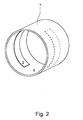
- magnetic-inductive flowmeter on a measuring line 1, not shown in detail magnetic field generating means for generating a measuring line 1 at least partially passing magnetic field, to which, in the Fig. 1 just indicated, two magnetic coils 2 belong, and two measuring electrodes 3 for detecting and tapping a induced voltage in the flowing medium measuring voltage.
- magnetic field generating means for generating a measuring line 1 at least partially passing magnetic field, to which, in the Fig. 1 just indicated, two magnetic coils 2 belong, and two measuring electrodes 3 for detecting and tapping a induced voltage in the flowing medium measuring voltage.
- Essential for that in the Fig. 1 shown magnetic-inductive flowmeter is also that the measuring line 1 inside at least partially, in the illustrated embodiment, a total of an electrically insulating cover layer 4 is provided.
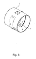
- the magneto-inductive flowmeter shown also includes a measuring tube 1, the magnetic field generating device and the measuring electrodes 3 receiving housing 5, which has a circular cross-section and is provided on both sides with flanges 6 in the embodiment.
- Fig. 2 and 3 show the measuring electrodes 3 strip-like. They have a length - in the circumferential direction of the measuring line 1 - from slightly less than a quarter of the Meß effetss to slightly more than half of the Meß effetselless, and they have direct, ie electrically conductive, so galvanic contact with the flowing medium.
- the measuring electrodes 3 made of the same material or a similar material as the cover layer 4 and the material of the measuring electrodes 3 has a much higher electrical conductivity than the material of the cover layer 4.
- the electrical conductivity of the material of the measuring electrodes 3 in the radial direction, in the flow direction of the flowing medium and in the direction of Meß einshuss is the same.
- a magnetic-inductive flowmeter further applies that the electrical conductivity of the material of the measuring electrodes 3 by a special chemical and / or physical treatment and / or increased by at least one additive. It is also important that the electrical conductivity of the material of the measuring electrodes 3 by about two times to about ten times higher than the electrical conductivity of the flowing medium.
- Fig. 2 and Fig. 3 - Are the measuring electrodes 3 over their entire length - in the circumferential direction of the measuring line 1 - in one piece.
- a magnetic-inductive flowmeter which has two measuring electrodes 3.
- still reference electrodes 7 to be realized. This is especially true when the magneto-inductive flowmeter according to the invention not only for flow measurement of a flowing medium, but also for conductivity measurement, for level measurement or for conductivity measurement and level measurement or only for conductivity measurement, only for level measurement or only for conductivity measurement and level measurement should be used, which is also possible without further notice.
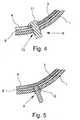
- the tapping of the measuring medium induced in the flowing medium and detected by the measuring electrodes 3 takes place galvanically.
- the measuring electrodes 3 are each assigned an outwardly leading terminal element 8.
- Fig. 4 this is realized in detail so that the measuring electrodes 3, the cover layer 4 and the measuring line 1 each have a through hole 9 and the connecting elements 8 are guided through the through holes 9 of the measuring electrodes 3, the cover layer 4 and the measuring line 1.
- the terminal elements 8 are provided with a lie in the interior of the measuring line 1 on the measuring electrodes 3, lenticular head.
- the shows Fig. 5 a realization of the galvanic tapping of the induced in the flowing medium and detected by the measuring electrodes 3 measuring voltage, which is characterized in that the measuring electrodes 3 are provided with the cover layer 4 and the measuring line 1 penetrating, circular cylindrical terminal receptacles.
- the connecting elements 8 are bolt-shaped and inserted into the terminal receptacles 11 of the measuring electrodes 3.
Abstract
Description
Die Erfindung betrifft ein magnetisch-induktives Durchflußmeßgerät zur Durchflußmessung eines strömenden Mediums, mit einer Meßleitung, mit einer Magnetfelderzeugungseinrichtung zur Erzeugung eines die Meßleitung wenigstens teilweise durchsetzenden Magnetfeldes und mit zwei Meßelektroden zum Erfassen und Abgreifen einer in dem strömenden Medium induzierten Meßspannung, wobei die Meßleitung innen zumindest teilweise mit einer elektrisch isolierenden Deckschicht versehen ist und wobei die Meßspannung galvanisch oder kapazitiv an den Meßelektroden abgegriffen werden kann. Dabei wird ausgegangen von einem magnetisch-induktiven Durchflußmeßgerät, dessen Meßleitung elektrisch leitend ist, das also eine metallische Meßleitung aufweist; nur dann ist zumindest teilweise eine elektrisch isolierende Deckschicht erforderlich. Diese elektrisch isolierende Deckschicht ist zumindest im Bereich der Meßelektroden vorgesehen. Die Dimension, die die Deckschicht wenigstens haben soll, hängt ab vom Durchmesser der Meßleitung. Üblicherweise hat die Deckschicht in der Längsrichtung der Meßleitung eine Ausdehnung, die etwa mindestens dem doppelten Durchmesser der Meßleitung entspricht. Die Meßleitung kann aber auch dann - teilweise oder ganz - mit einer Deckschicht versehen sein, wenn sie nicht elektrisch leitend ist. Üblicherweise, aber nicht funktionsnotwendig, gehört zu einem magnetisch-induktiven Durchflußmeßgerät der in Rede stehenden Art noch ein die Meßleitung, vorzugsweise auch die Magnetfelderzeugungseinrichtung und die Meßelektroden aufnehmendes Gehäuse, wobei das Gehäuse üblicherweise einen kreisförmigen Querschnitt hat.The invention relates to a magnetic-inductive flowmeter for measuring the flow of a flowing medium, with a measuring line, with a magnetic field generating means for generating a measuring line at least partially passing magnetic field and with two measuring electrodes for detecting and tapping an induced in the flowing medium measuring voltage, the measuring line inside at least partially provided with an electrically insulating cover layer and wherein the measuring voltage can be tapped galvanically or capacitively at the measuring electrodes. It is assumed that a magnetic-inductive flowmeter, the measuring line is electrically conductive, which thus has a metallic measuring line; only then an electrically insulating cover layer is at least partially required. This electrically insulating cover layer is provided at least in the region of the measuring electrodes. The dimension that the cover layer should at least depend on the diameter of the measuring line. Usually, the cover layer in the longitudinal direction of the measuring line has an extent which corresponds approximately to at least twice the diameter of the measuring line. But the measuring line can also - partially or completely - be provided with a cover layer, if it is not electrically conductive. Usually, but not functionally necessary, belongs to a magnetic-inductive flowmeter of the type in question nor the measuring line, preferably also the magnetic field generating device and the measuring electrodes receiving housing, the housing usually has a circular cross-section.
Magnetisch-induktive Durchflußmeßgeräte sind sehr umfangreich im Stand der Technik seit Jahrzehnten bekannt; dazu wird exemplarisch auf die Literaturstelle "
Das grundlegende Prinzip eines magnetisch-induktiven Durchflußmeßgeräts zur Durchflußmessung eines strömenden Mediums geht auf Faraday zurück, der bereits im Jahre 1832 vorgeschlagen hat, das Prinzip der elektrodynamischen Induktion zur Messung der Strömungsgeschwindigkeit eines strömenden Mediums anzuwenden. Nach dem faraday'schen Induktionsgesetz entsteht in einem strömenden Medium, das Ladungsträger mit sich führt und durch ein Magnetfeld hindurchfließt, eine elektrische Feldstärke senkrecht zur Strömungsrichtung und senkrecht zum Magnetfeld. Das faraday'sche Induktionsgesetz wird bei magnetisch-induktiven Durchflußmeßgeräten dadurch ausgenutzt, daß mittels einer Magnetfelderzeugungseinrichtung, die üblicherweise zwei bestromte Magnetspulen aufweist, ein Magnetfeld erzeugt und wenigstens teilweise durch eine Meßleitung geführt wird, wobei das erzeugte Magnetfeld wenigstens eine Komponente aufweist, die senkrecht zur Strömungsrichtung verläuft. Innerhalb des Magnetfeldes liefert jedes sich durch das Magnetfeld bewegende und eine gewisse Anzahl von Ladungsträgern aufweisende Volumenelement des strömenden Mediums mit der in diesem Volumenelement entstehenden Feldstärke einen Beitrag zu einer von den Meßelektroden erfaßbaren und - galvanisch oder kapazitiv - abgreifbaren Meßspannung.The basic principle of a magnetic-inductive flowmeter for measuring the flow of a flowing medium goes back to Faraday, which has already proposed in 1832 to apply the principle of electrodynamic induction for measuring the flow velocity of a flowing medium. According to Faraday's law of induction, an electric field strength perpendicular to the flow direction and perpendicular to the magnetic field is generated in a flowing medium, which carries charge carriers with it and flows through a magnetic field. The Faraday's law of induction is exploited in magnetic-inductive flowmeters in that by means of a magnetic field generating device, which usually has two energized magnetic coils, generates a magnetic field and at least partially passed through a measuring line, wherein the generated magnetic field has at least one component perpendicular to the Flow direction runs. Within the magnetic field, each volume element of the flowing medium moving through the magnetic field and having a certain number of charge carriers, with the field strength arising in this volume element, contributes to a measuring voltage which can be detected by the measuring electrodes and can be tapped galvanically or capacitively.
Sind, wie weiter oben ausgeführt, magnetisch-induktive Durchflußmeßgeräte seit Jahrzehnten umfangreich und in einer kaum noch überschaubaren Vielzahl von Ausführungsformen bekannt, so sind auch in bezug auf magnetisch-induktive Durchflußmeßgeräte, wie in vielen weitgehend entwickelten Gebieten der Technik, immer noch Fortschritte erwünscht und auch möglich. Das gilt auch und in besonderem Maße in bezug auf die Meßelektroden solcher magnetisch-induktiver Durchflußmeßgeräte.Are, as stated above, magnetic flowmeters for decades extensive and known in a barely manageable variety of embodiments, so are also with respect to magnetic flowmeters, as in many highly developed areas of technology, still progress and desired also possible. This also applies in particular to the measuring electrodes of such magnetic-inductive flowmeters.
Bei magnetisch-induktiven Durchflußmeßgeräten der in Rede stehenden Art kann das strömende Medium eine gasfreie oder zumindest weitgehend gasfreie Flüssigkeit sein, bei dem strömenden Medium kann es sich jedoch auch um eine Flüssigkeit handeln, die mehr oder weniger Gasanteile enthält. Im übrigen kann bei den in Rede stehenden magnetisch-induktiven Durchflußmeßgeräten die Meßleitung betriebsmäßig vollständig gefüllt oder auch nur teilweise gefüllt sein.In magnetic-inductive flowmeters of the type in question, the flowing medium may be a gas-free or at least substantially gas-free liquid, but in the flowing medium may also be a liquid containing more or less gas fractions. Moreover, in the magnetic-inductive flow measuring devices in question, the measuring line can be completely filled in operation or else only partially filled.
Einleitend ist gesagt worden, daß die Erfindung ein magnetisch-induktives Durchflußmeßgerät zur Durchflußmessung eines strömenden Mediums betrifft. Ein solches magnetisch-induktives Durchflußmeßgerät erlaubt aber nicht nur die Durchflußmessung eines strömenden Mediums, vielmehr auch eine Leitfähigkeitsmessung und/oder eine Füllstandsmessung, wobei mit der Füllstandsmessung eine Aussage darüber gewonnen werden kann, ob die Meßleitung vollständig oder nur teilweise gefüllt ist. Folglich kann ein magnetisch-induktives Durchflußmeßgerät der eingangs beschriebenen Art zur Durchflußmessung, zur Leitfähigkeitsmessung und/oder zur Füllstandsmessung verwendet werden. Üblicherweise werden magnetisch-induktive Durchflußmeßgeräte nicht nur für eine Leitfähigkeitsmessung und nicht nur für eine Füllstandsmessung eingesetzt. Wird vielmehr auch eine Leitfähigkeitsmessung und/oder eine Füllstandsmessung vorgesehen, so dient ein magnetisch-induktives Durchflußmeßgerät der in Rede stehenden Art in der Regel für eine Durchflußmessung und eine Leitfähigkeitsmessung, für eine Durchflußmessung und eine Füllstandsmessung oder für eine Durchflußmessung, eine Leitfähigkeitsmessung und eine Füllstandsmessung. Möglich ist es jedoch auch, ein solches magnetisch-induktives Durchflußmeßgerät auch nur für eine Leitfähigkeitsmessung, nur für eine Füllstandsmessung oder nur für eine Leitfähigkeitsmessung und eine Füllstandsmessung einzusetzen. Nachfolgend wird aber immer von einem magnetisch-induktiven Durchflußmeßgerät zur Durchflußmessung eines strömenden Mediums ausgegangen. Dessen ungeachtet gilt das, was nachfolgend ausgeführt wird, auch stets für ein magnetisch-induktives Durchflußmeßgerät zur Durchflußmessung und zur Leitfähigkeitsmessung, zur Durchflußmessung und zur Füllstandsmessung, zur Durchflußmessung, zur Leitfähigkeitsmessung und zur Füllstandsmessung, zur Leitfähigkeitsmessung, zur Füllstandsmessung oder zur Leitfähigkeitsmessung und zur Füllstandsmessung.In the introduction, it has been stated that the invention relates to a magnetic-inductive flowmeter for measuring the flow of a flowing medium. However, such a magnetic-inductive flowmeter allows not only the flow measurement of a flowing medium, but also a conductivity measurement and / or a level measurement, with the level measurement, a statement can be obtained as to whether the measuring line is completely or only partially filled. Consequently, a magneto-inductive flowmeter of the type described above for flow measurement, conductivity measurement and / or level measurement can be used. Usually magnetic flowmeters are not only used for a conductivity measurement and not only for a level measurement. If, instead, a conductivity measurement and / or a fill level measurement are also provided, then a magneto-inductive flowmeter of the type in question usually serves for a flow measurement and a conductivity measurement, for a flow measurement and a fill level measurement or for a flow measurement, a conductivity measurement and a fill level measurement , However, it is also possible to use such a magnetic-inductive flowmeter only for a conductivity measurement, only for a level measurement or only for a conductivity measurement and level measurement. Subsequently, however, it is always assumed that a magnetic-inductive flowmeter for measuring the flow of a flowing medium. Regardless, what is said below is always applicable to a magnetic flowmeter for flow measurement and conductivity measurement, flow measurement and level measurement, flow measurement, conductivity measurement and level measurement, conductivity measurement, level measurement or conductivity measurement and level measurement ,
Magnetisch-induktive Durchflußmeßgeräte, bei denen die Meßleitung zumindest teilweise eine elektrisch isolierende Deckschicht aufweist, sind vielfach bekannt (vergleiche die deutschen Offenlegungsschriften
Weiter oben ist bereits ausgeführt, daß trotz der Tatsache, daß magnetisch-induktive Durchflußmeßgeräte seit Jahrzehnten umfangreich und in einer kaum noch überschaubaren Vielzahl von Ausführungsformen bekannt sind, auch in bezug auf magnetisch-induktive Durchflußmeßgeräte immer noch Fortschritte erwünscht und auch möglich sind, was in besonderem Maße auch in bezug auf die Meßelektroden solcher magnetisch-induktiver Durchflußmeßgeräte gilt. Folglich liegt der Erfindung die Aufgabe zugrunde, die bekannten magnetisch-induktiven Durchflußmeßgeräte, von denen die Erfindung ausgeht, in bezug auf die funktionsnotwendigen Meßelektroden verbessernd auszugestalten und weiterzubilden.It has already been stated above that, despite the fact that magnetic-inductive flowmeters have been known extensively and in a barely manageable multiplicity of embodiments for decades, progress is also desired and also possible with regard to magnetic-inductive flowmeters especially true with respect to the measuring electrodes of such magnetic-inductive flowmeters. Consequently, the invention has the object, the known magnetic-inductive flowmeters, from which the invention proceeds, with respect to the functionally necessary measuring electrodes improve and further develop.
Eine bevorzugte Ausführungsform eines erfindungsgemäßen magnetisch-induktiven Durchflußmeßgeräts der eingangs beschriebenen Art ist zunächst und im wesentlichen dadurch gekennzeichnet, daß die Meßelektroden streifenartig ausgeführt sind, eine Länge - in Umfangsrichtung der Meßleitung - von etwas weniger als einem Viertel des Meßleitungsumfangs bis etwas mehr als der Hälfte des Meßleitungsumfangs haben und direkten, d. h. elektrisch leitenden, also galvanischen Kontakt zum strömenden Medium haben. Eine solche Ausführungsform hat gegenüber den im Stand der Technik bekannten Ausführungsformen funktionale, insbesondere aber konstruktive und herstellungstechnische Vorteile. Das gilt insbesondere dann, aber nicht nur, wenn nach einer weiteren Lehre der Erfindung, der auch für sich, also losgelöst von dem, was zuvor ausgeführt worden ist, besondere Bedeutung zukommt, die Meßelektroden aus dem gleichen Material oder einem gleichartigen Material wie die Deckschicht bestehen und das Material der Meßelektroden eine wesentlich höhere elektrische Leitfähigkeit hat als das Material der Deckschicht.A preferred embodiment of a magneto-inductive flowmeter according to the invention of the type described above is initially and essentially characterized in that the measuring electrodes are designed strip-like, a length - in the circumferential direction of the measuring line - from slightly less than a quarter of the Meßleitungsumfangs to slightly more than half Have the Meßleitungsumfangs and direct, ie electrically conductive, so have galvanic contact with the flowing medium. Such an embodiment has over the known in the prior art embodiments functional, but in particular constructive and manufacturing advantages. This is especially true, but not only, if, according to another teaching of the invention, which also for itself, so detached from what has been stated above, particular importance, the measuring electrodes of the same material or a similar material as the cover layer exist and the material of the measuring electrodes has a much higher electrical conductivity than the material of the cover layer.
Weiter oben ist ausgeführt, daß als Material für die Deckschicht in der Regel Kunststoffe verwendet werden, z. B. Polyurethan, Polyolefin, Polytetrafluorethylen oder Polyetheretherketon. Wenn zuvor eine besondere Lehre der Erfindung dahingehend beschrieben ist, daß die Meßelektroden aus dem gleichen Material oder einem gleichartigen Material wie die Deckschicht bestehen, so muß das - klarstellend bzw. einschränkend - natürlich dahingehend verstanden werden, daß sowohl bei gleichem Material als auch bei gleichartigem Material auch realisiert sein muß, daß das Material der Meßelektroden eine wesentliche höhere elektrische Leitfähigkeit hat als das Material der Deckschicht. Gleiches Material kann hier also nicht absolut identisches Material meinen.It is stated above that plastics are usually used as material for the cover layer, for. As polyurethane, polyolefin, polytetrafluoroethylene or polyetheretherketone. If a special teaching of the invention is described to the effect that the measuring electrodes are made of the same material or a similar material as the covering layer, this must be understood, of course, as clarifying or restricting, that both with the same material and with the same material, it must also be realized that the material of the measuring electrodes has a considerably higher electrical conductivity than the material of the covering layer. The same material can not mean absolutely identical material here.
Für die zuvor erläuterte Lehre der Erfindung, der, wie gesagt, besondere Bedeutung zukommt, ist, wie ausgeführt, auch wesentlich, daß das Material der Meßelektroden eine wesentlich höhere elektrische Leitfähigkeit hat als das Material der Deckschicht. Die notwendige höhere elektrische Leitfähigkeit des Materials der Meßelektroden gegenüber der elektrischen Leitfähigkeit des Materials der Deckschicht kann durch eine besondere chemische und/oder physikalische Behandlung und/oder durch mindestens einen Zusatzstoff erreicht werden. Inwieweit eine besondere chemische und/oder physikalische Behandlung und/oder ein Zusatzstoff oder Zusatzstoffe erforderlich sind bzw. ist, um zu Erreichen, daß das Material der Meßelektroden eine wesentlich höhere elektrische Leitfähigkeit hat als das Material der Deckschicht, hängt natürlich auch und vor allem davon ab, ob, bejahendenfalls, inwieweit das für die Meßelektroden verwendete Material auch ohne eine besondere chemische und/oder physikalische Behandlung und ohne einen Zusatzstoff eine höhere elektrische Leitfähigkeit hat als das Material der Deckschicht. Je geringer sich anfänglich die elektrische Leitfähigkeit des Materials der Meßelektroden von der elektrischen Leitfähigkeit des Materials der Deckschicht unterscheidet, desto mehr muß natürlich getan werden, damit schlußendlich das Material der Meßelektroden eine wesentlich höhere elektrische Leitfähigkeit hat als das Material der Deckschicht.For the above-described teaching of the invention, which, as I said, is of particular importance, is, as stated, also essential that the material of the measuring electrodes has a much higher electrical conductivity than the material of the cover layer. The necessary higher electrical conductivity of the material of the measuring electrodes relative to the electrical conductivity of the material of the cover layer can be achieved by a special chemical and / or physical treatment and / or by at least one additive. To what extent a special chemical and / or physical treatment and / or an additive or additives is required or to achieve that the material of the measuring electrodes has a much higher electrical conductivity than the material of the cover layer, of course, and above all depends on it if, if so, to what extent the material used for the measuring electrodes has a higher electrical conductivity than the material of the covering layer even without special chemical and / or physical treatment and without an additive. The lower the initial electrical conductivity of the material of the measuring electrodes differs from the electrical conductivity of the material of the cover layer, the more must of course be done so that ultimately the material of the measuring electrodes has a much higher electrical conductivity than the material of the cover layer.
Bisher ist nur darauf abgestellt worden, daß das Material der Meßelektroden eine wesentlich höhere elektrische Leitfähigkeit haben muß als daß Material der Deckschicht. Notwendig ist aber auch, daß die elektrische Leitfähigkeit des Materials der Meßelektroden wesentlich höher ist als die elektrische Leitfähigkeit des strömenden Mediums, vorzugsweise um etwa das Zweifache bis etwa das Zehnfache. Dabei ist auslegungsmäßig zu berücksichtigen, mit welcher elektrischen Leitfähigkeit in dem strömenden Medium zu rechnen ist.So far, it has only been pointed out that the material of the measuring electrodes must have a much higher electrical conductivity than that of the covering material. But it is also necessary that the electrical conductivity of the material of the measuring electrodes is substantially higher than the electrical conductivity of the flowing medium, preferably by about twice to about ten times. In this case, it must be taken into consideration which electrical conductivity is to be expected in the flowing medium.
Die elektrische Leitfähigkeit beträgt bei Trinkwasser etwa 500 µScm und bei Abwasser etwa 5000 µScm.The electrical conductivity is about 500 μScm for drinking water and about 5000 μScm for wastewater.
Weiter oben ist bereits darauf hingewiesen worden, daß bei bekannten magnetisch-induktiven Durchflußmeßgeräten als Material für die Deckschicht in der Regel Kunststoffe verwendet werden, z. B. Polyurethan, Polyolefin, Polytetrafluorethylen oder Polyetheretherketon. Solche Materialien können auch bei dem erfindungsgemäßen magnetisch-induktiven Durchflußmeßgerät für die Deckschicht der Meßleitung verwendet werden.It has already been pointed out above that in the case of known magnetic-inductive flowmeters, plastics are generally used as the material for the cover layer, eg. As polyurethane, polyolefin, polytetrafluoroethylene or polyetheretherketone. Such materials can also be used in the magnetic inductive flowmeter according to the invention for the cover layer of the measuring line.
Als Material für die Meßelektroden kann grundsätzlich ein Polymer verwendet werden, z. B. Polyurethan (PUR), Polyamid (PA), Polyethylen / Polyethen (PE), Polypropylen / Polypropeen (PP), ein unter der Marke Teflon bekannter Kunststoff (PFA, PTFE, ETFE) oder Gummi verschiedenster Art.As a material for the measuring electrodes, in principle, a polymer can be used, for. As polyurethane (PUR), polyamide (PA), polyethylene / polyethene (PE), polypropylene / Polypropeen (PP), a known under the brand Teflon plastic (PFA, PTFE, ETFE) or rubber of various kinds.
Wesentlich für die weiter oben erläuterte Lehre der Erfindung, der besondere Bedeutung zukommt, ist, daß das Material der Meßelektroden eine wesentliche höhere elektrische Leitfähigkeit hat als das Material der Deckschicht. Dies zu erreichen, gibt es eine Mehrzahl von Möglichkeiten. Dazu ist bereits weiter oben darauf hingewiesen, daß die notwendige höhere elektrische Leitfähigkeit des Materials der Meßelektroden gegenüber der elektrischen Leitfähigkeit des Materials der Deckschicht durch eine besondere chemische und/oder physikalische Behandlung und/oder durch mindestens einen Zusatzstoff erreicht werden kann.Essential for the above-described teaching of the invention, which is of particular importance, is that the material of the measuring electrodes has a significantly higher electrical conductivity than the material of the cover layer. To achieve this, there are a number of possibilities. For this purpose, it has already been pointed out above that the necessary higher electrical conductivity of the material of the measuring electrodes relative to the electrical conductivity of the material of the covering layer can be achieved by a special chemical and / or physical treatment and / or by at least one additive.
Eine besonders bevorzugte Ausführungsform des erfindungsgemäßen magnetisch-induktiven Durchflußmeßgeräts ist dadurch gekennzeichnet, daß als Material für die Meßelektroden ein Polymer mit extrinsischer Leitfähigkeit oder ein Material mit intrinsischer Leitfähigkeit verwendet ist.A particularly preferred embodiment of the magneto-inductive flowmeter according to the invention is characterized in that a polymer with extrinsic conductivity or a material with intrinsic conductivity is used as the material for the measuring electrodes.
Extrinsische Leitfähigkeit bezeichnet den Anteil der Leitfähigkeit eines Festkörpers, der durch den Einbau von Fremdatomen (äußerer Einfluß ⇒ extrinsisch) in das Kristallgitter hervorgerufen wird (vgl. "Wikipedia, die freie Enzyklopädie"). Das Einbringen von Fremdatomen wird Dotieren genannt. Die Fremdatome bewirken eine Erhöhung der Leitfähigkeit, da sie - je nach Zahl ihrer Valenzelektroden - zusätzliche Leerstellen oder zusätzliche freibewegliche Ladungen in den Festkörper einbringen. Die extrinsische Leitfähigkeit ist bei tiefen Temperaturen nahezu temperaturunabhängig und besteht auch noch bei 0 K.Extrinsic conductivity refers to the proportion of the conductivity of a solid, which is caused by the incorporation of foreign atoms (external influence ⇒ extrinsic) in the crystal lattice (see "Wikipedia, the free encyclopedia"). The introduction of foreign atoms is called doping. The foreign atoms cause an increase in the conductivity, since - depending on the number of their valence electrodes - additional vacancies or additional freely movable Insert charges into the solid. The extrinsic conductivity is almost independent of temperature at low temperatures and also exists at 0 K.
Intrinsische Leitfähigkeit entsteht dadurch, daß Festkörper (von sich aus ⇒ intrinsisch) dazu neigen, Gitterfehler auszubilden und damit eine Ladungsbewegung, also eine Ionenleitung ermöglichen, also elektrisch leitfähig sind (vgl. "Wikipedia, die freie Enzyklopädie"). In einem Festkörper können Gitterfehler wie z. B. Schottky-Defekte und Frenkel-Defekte auftreten. Sie sind thermodynamisch begünstigt, da sie einen Entropiegewinn bringen. Das System neigt demnach bis zu einem gewissen Grad dazu, Defekte auszubilden. Diese Fehler werden als intrinsische Fehler bezeichnet. Die Defektkonzentration ist temperaturabhängig. Sie steigt mit der Temperatur und hat bei 0 K den Wert Null. Intrinsische Defekte sorgen folglich bei Temperaturen > 0 K für bewegliche Ladungen und damit für eine intrinsische elektrische Leitfähigkeit.Intrinsic conductivity arises from the fact that solids (intrinsically ⇒ intrinsically) tend to form lattice defects and thus allow a charge movement, ie an ionic conduction, ie are electrically conductive (see "Wikipedia, the free encyclopedia"). In a solid, lattice defects such. B. Schottky defects and Frenkel defects occur. They are thermodynamically favored, as they bring an entropy gain. The system therefore tends to form defects to some extent. These errors are called intrinsic errors. The defect concentration is temperature-dependent. It rises with the temperature and has the value zero at 0 K. Consequently, intrinsic defects at temperatures> 0 K cause mobile charges and thus intrinsic electrical conductivity.
Materialien mit elektrischer Leitfähigkeit können sowohl eine extrensische Leitfähigkeit als auch eine intrinsische Leitfähigkeit haben. Bei tiefen Temperaturen dominiert die extrinsische Leitfähigkeit, während sie bei steigender Temperatur von der intrinsischen Leitfähigkeit überdeckt wird (vgl. wieder "Wikipidea, die freie Enzyklopädie").Materials having electrical conductivity may have both extrinsic conductivity and intrinsic conductivity. At low temperatures, extrinsic conductivity dominates, while at higher temperatures it is masked by intrinsic conductivity (see again "Wikipidea, the Free Encyclopedia").
Bei dem erfindungsgemäßen magnetisch-induktiven Durchflußmeßgerät kann als Zusatzstoff bzw. können als Zusatzstoffe für das Material der Meßelektroden Kohlenstoff, z. B. in Form von Graphit, auch in der Form von Kohlenstofffasern, Metall oder anderes elektrisches Material, jeweils vorzugsweise pulverförmig oder faserförmig, verwendet sein.In the magnetic-inductive flowmeter according to the invention can be used as additive or as additives for the material of the measuring electrodes carbon, z. B. in the form of graphite, also in the form of carbon fibers, metal or other electrical material, each preferably in powder or fibrous form, be used.
Bisher ist im wesentlichen abgestellt worden auf die elektrische Leitfähigkeit des Materials der Meßelektroden relativ zur elektrischen Leitfähigkeit der Deckschicht, auf die elektrische Leitfähigkeit des Materials der Meßelektroden relativ zur elektrischen Leitfähigkeit des strömenden Mediums, auf besonders geeignete Materialien für die Meßelektroden und auf die elektrische Leitfähigkeit der Meßelektroden beeinflussende Aspekte. Von Bedeutung für erfindungsgemäße magnetisch-induktive Durchflußmeßgeräte sind aber auch die Form der Meßelektroden, die Anordnung der Meßelektroden relativ zur Deckschicht, Möglichkeiten des Abgreifens der von den Meßelektroden erfaßten Meßspannung sowie geeignete bzw. besonders vorteilhafte Verfahren zur Herstellung der erfindungsgemäßen magnetisch-induktiven Durchflußmeßgeräte. Darauf soll im folgenden eingegangen werden.So far, it has been turned off substantially on the electrical conductivity of the material of the measuring electrodes relative to the electrical conductivity of the cover layer, the electrical conductivity of the material of the measuring electrodes relative to the electrical conductivity of the flowing medium, particularly suitable materials for the measuring electrodes and the electrical conductivity of the Measuring electrodes influencing aspects. Of importance for magnetic-inductive flow measuring devices according to the invention but are also the shape of the measuring electrodes, the arrangement of the measuring electrodes relative to Top layer, possibilities of tapping the measured voltage detected by the measuring electrodes and suitable or particularly advantageous method for producing the magnetic-inductive flow measuring devices according to the invention. This will be discussed below.
Bei bevorzugten Ausführungsformen erfindungsgemäßer magnetisch-induktiver Durchflußmeßgeräte können die Meßelektroden - auf die Meßelektroden in gestreckter, gleichsam "abgewickelter" Form gesehen - eine rechteckige Form oder eine über den Meßleitungsumfang veränderliche Form haben, z. B. eine dreieckige oder eine rhombische Form. Im übrigen können die Meßelektroden einen kreisförmigen, einen elliptischen, einen quadratischen, einen rechteckigen, einen achteckigen oder einen teilweise kreisförmigen und/oder elliptischen und/oder quadratischen und/oder rechteckigen und/oder achteckigen Querschnitt aufweisen. In bezug auf die Form der Meßelektroden ist noch darauf hinzuweisen, daß diese an ihren Enden abgerundet sein können oder in einen kreisförmigen Querschnitt übergehen können und/oder daß sie in Strömungsrichtung des strömenden Mediums einen venturiartigen Querschnitt aufweisen können.In preferred embodiments of inventive magnetic-inductive flowmeters, the measuring electrodes - seen on the measuring electrodes in stretched, as it were "unwound" form - have a rectangular shape or a variable over the Meßleitungsumfang shape, z. B. a triangular or a rhombic shape. Moreover, the measuring electrodes can have a circular, an elliptical, a square, a rectangular, an octagonal or a partially circular and / or elliptical and / or square and / or rectangular and / or octagonal cross section. With respect to the shape of the measuring electrodes is also to be noted that they may be rounded at their ends or may be in a circular cross section and / or that they may have a venturi-like cross-section in the flow direction of the flowing medium.
Weiter oben ist ausgeführt worden, daß eine bevorzugte Ausführungsform eines erfindungsgemäßen magnetisch-induktiven Durchflußmeßgeräts zunächst und im wesentlichen dadurch gekennzeichnet ist, daß die Meßelektroden streifenartig ausgeführt sind, eine Länge - in Umfangsrichtung der Meßleitung - von etwas weniger als einem Viertel des Meßleitungsumfangs bis etwas mehr als der Hälfte des Meßleitungsumfangs haben und direkten, d. h. elektrisch leitenden, also galvanischen Kontakt zum strömenden Medium haben. Diese streifenartige Ausführung der Meßelektroden kann eine einstückige Ausführung sein, die Meßelektroden können aber auch aus mehreren Teilelektroden bestehen.It has been stated above that a preferred embodiment of a magneto-inductive flowmeter according to the invention is first and essentially characterized in that the measuring electrodes are strip-like, a length - in the circumferential direction of the measuring line - from a little less than a quarter of the Meßleitungsumfangs to something more as half of the Meßleitungsumfangs and direct, d. H. electrically conductive, so have galvanic contact with the flowing medium. This strip-like design of the measuring electrodes may be a one-piece design, but the measuring electrodes may also consist of a plurality of partial electrodes.
Die Anordnung der Meßelektroden relativ zur Deckschicht kann so sein, daß die in das Innere der Meßleitung gerichtete Oberfläche der Meßelektroden bündig ist zu der in das Innere der Meßleitung gerichteten Oberfläche der Deckschicht, die Meßelektroden also gleichsam vollständig in der Deckschicht integriert sind. Das strömende Medium findet also einen durchgängig glatten, Vorsprünge oder Rücksprünge nicht aufweisenden Strömungskanal vor. Es kann aber auch vorteilhaft sein, die Anordnung so zu treffen, daß die in das Innere der Meßleitung gerichtete Oberfläche der Meßelektroden in bezug auf die in das Innere der Meßleitung gerichtete Oberfläche der Deckschicht vorspringt oder zurückspringt. Dadurch können im Bereich der Meßelektroden Strömungssituationen entstehen, die dazu führen, daß die Meßelektroden die in dem strömenden Medium induzierte Meßspannung besonders gut erfassen können.The arrangement of the measuring electrodes relative to the cover layer may be such that the surface of the measuring electrodes directed into the interior of the measuring line is flush with the surface of the cover layer directed into the interior of the measuring line, ie the measuring electrodes are, as it were, completely integrated in the cover layer. The flowing medium thus finds a consistently smooth, projections or recesses not having flow channel in front. But it may also be advantageous to make the arrangement so that the directed into the interior of the measuring line surface of the measuring electrodes with respect to the directed into the interior of the measuring line surface of the cover layer protrudes or springs back. As a result, flow situations can arise in the region of the measuring electrodes which lead to the measuring electrodes being able to detect the measuring voltage induced in the flowing medium particularly well.
Funktionsnotwendig für ein magnetisch-induktives Durchflußmeßgerät der in Rede stehenden Art sind genau zwei Elektroden, senkrecht zum Magnetfeld und senkrecht zur Strömungsrichtung des strömenden Mediums. Es kann jedoch von Vorteil sein, zusätzlich zu den beiden funktionsnotwendigen Meßelektroden mindestens eine Referenzelektrode vorzusehen. Das kann sich besonders dann, aber nicht nur dann, empfehlen, wenn das erfindungsgemäße magnetisch-induktive Durchflußmeßgerät auch zur Leitfähigkeitsmessung, zur Füllstandsmessung, zur Leitfähigkeitsmessung und zur Füllstandsmessung oder nur zur Leitfähigkeitsmessung, zur Füllstandsmessung oder zur Leitfähigkeitsmessung und zur Füllstandsmessung verwendet werden soll. Davon unabhängig kann es von Vorteil sein, bei erfindungsgemäßen magnetisch-induktiven Durchflußmeßgeräten mehrere Meßelektroden in Strömungsrichtung des strömenden Mediums hintereinander anzuordnen, so daß nicht nur zwei Meßelektroden, sondern z. B. vier Meßelektroden oder gar sechs Meßelektroden vorgesehen sind. Bei einer solchen Anordnung kann man einerseits die von jeweils zwei Meßelektroden erfaßten Meßspannungen mitteln, was zu einem genaueren Meßergebnis führen kann. Die Anordnung von mehreren Meßelektroden in Strömungsrichtung des strömenden Mediums hintereinander kann auch den Vorteil haben, daß gleichsam mehrere Meßsystems zur Verfügung stehen, bei insgesamt vier Meßelektroden also zwei Meßsysteme, bei insgesamt sechs Meßelektroden also drei Meßsysteme. Das hat den Vorteil, daß ein solches magnetisch-induktives Durchflußmeßgerät auch dann funktionsfähig ist und bleibt, wenn die Durchflußmessung über zwei sich gegenüberliegende Meßelektroden, aus welchen Gründen auch immer, fehlerhaft ist oder gar ausfällt.Functional necessary for a magnetic-inductive flowmeter of the type in question are exactly two electrodes, perpendicular to the magnetic field and perpendicular to the flow direction of the flowing medium. However, it may be advantageous to provide at least one reference electrode in addition to the two functionally necessary measuring electrodes. This may be especially, but not only, recommendable if the magnetic inductive flowmeter according to the invention is also to be used for conductivity measurement, for level measurement, for conductivity measurement and for level measurement or only for conductivity measurement, for level measurement or for conductivity measurement and level measurement. Regardless, it may be advantageous to arrange a plurality of measuring electrodes in the flow direction of the flowing medium in the flow direction of the flowing medium in the flow direction of the flowing medium according to the invention in magnetic flowmeters, so that not only two measuring electrodes, but z. B. four measuring electrodes or even six measuring electrodes are provided. In such an arrangement, one can average the detected by two measuring electrodes measuring voltages, which can lead to a more accurate measurement result. The arrangement of a plurality of measuring electrodes in the flow direction of the flowing medium one behind the other can also have the advantage that there are at least several measuring system available, with a total of four measuring electrodes so two measuring systems, with a total of six measuring electrodes so three measuring systems. This has the advantage that such a magneto-inductive flowmeter is also functional and remains when the flow measurement via two opposing measuring electrodes, for whatever reason, is faulty or even fails.
Wie schon ausgeführt, muß die im strömenden Medium induzierte, von den Meßelektroden erfaßte Meßspannung natürlich von den Meßelektroden abgegriffen werden, also vom "Entstehungsort", dem Inneren der Meßleitung, nach außen verbracht werden, damit die induzierte und erfaßte Meßspannung ausgewertet werden kann.As already stated, the measuring voltage induced in the flowing medium and detected by the measuring electrodes naturally has to be picked up by the measuring electrodes be spent so from the "place of origin", the interior of the measuring line to the outside, so that the induced and detected measuring voltage can be evaluated.
Eingangs ist ausgeführt, daß die Meßspannung galvanisch oder kapazitiv von den Meßelektroden abgegriffen werden kann. Bei den erfindungsgemäßen magnetisch-induktiven Durchflußmeßgeräten empfiehlt sich ein galvanisches Abgreifen. Folglich ist bei erfindungsgemäßen magnetisch-induktiven Durchflußmeßgeräten vorzugsweise den Meßelektroden jeweils mindestens ein nach außen führendes Anschlußelement zugeordnet. Im einzelnen können dazu die Meßelektroden, die Deckschicht und die Meßleitung jeweils mindestens eine Durchgangsbohrung aufweisen und die Anschlußelemente durch die Durchgangsbohrungen der Meßelektroden, der Deckschicht und der Meßleitung geführt sein. Bei dieser Ausführungsform können die Anschlußelemente mit einen im Inneren der Meßleitung auf den Meßelektroden aufliegenden, vorzugsweise linsenförmigen Kopf versehen sein. Eine andere Ausführungsform erfindungsgemäßer magnetisch-induktiver Durchflußmeßgeräte ist in bezug auf das Abgreifen der in dem strömenden Medium induzierten und von den Meßelektroden erfaßten Meßspannung dadurch gekennzeichnet, daß die Meßelektroden mit die Deckschicht und die Meßleitung durchdringenden, vorzugsweise kreiszylindrischen Anschlußaufnahmen versehen sind; diese Anschlußaufnahmen können vorzugsweise einstückig mit den Meßelektroden ausgeführt sein. Bei dieser Ausführungsform empfiehlt es sich dann, die Anschlußelemente bolzenförmig auszuführen und in die Anschlußaufnahmen der Meßelektroden einzustecken.Input is carried out that the measuring voltage can be tapped galvanically or capacitively from the measuring electrodes. In the magnetic-inductive flow measuring devices according to the invention, a galvanic tapping is recommended. Consequently, in magneto-inductive flowmeters according to the invention, preferably at least one outwardly leading connection element is associated with the measuring electrodes. In detail, the measuring electrodes, the cover layer and the measuring line can each have at least one through-hole and the connecting elements can be guided through the through-holes of the measuring electrodes, the cover layer and the measuring line. In this embodiment, the connection elements may be provided with a preferably lenticular head resting on the measuring electrodes in the interior of the measuring line. Another embodiment of magnetic-inductive flow measuring devices according to the invention is characterized with respect to the tapping of the measuring voltage induced in the flowing medium and detected by the measuring electrodes, characterized in that the measuring electrodes are provided with the cover layer and the measuring line penetrating, preferably circular cylindrical terminal receptacles; These connection receptacles can preferably be made in one piece with the measuring electrodes. In this embodiment, it is then recommended to carry out the connecting elements bolt-shaped and plug into the terminal receptacles of the measuring electrodes.
Zur Lehre der Erfindung gehört nicht nur das zuvor in verschiedenen Ausführungsformen beschriebenen magnetisch-induktive Durchflußmeßgerät, zur Lehre der Erfindung gehören vielmehr auch bevorzugte Verfahren zur Herstellung magnetisch-induktiver Durchflußmeßgeräte, die die Deckschicht, die Meßelektroden, die Realisierung der Deckschicht und der Meßelektroden und die Verbindung der Meßelektroden mit der Deckschicht im Fokus haben.The teaching of the invention includes not only the previously described in various embodiments magnetic-inductive flowmeter, the teaching of the invention but rather include preferred method for producing magnetic-inductive flowmeters, the cover layer, the measuring electrodes, the realization of the cover layer and the measuring electrodes and the Focusing connection of the measuring electrodes with the cover layer.
Zunächst ist ein erfindungsgemäßes Verfahren zur Herstellung eines magnetisch-induktiven Durchflußmeßgeräts der in Rede stehenden Art, bei dem die Deckschicht und die Meßelektroden aus Gummi bestehen, dadurch gekennzeichnet, daß die Meßelektroden in die Deckschicht einvulkanisiert oder auf die Deckschicht aufvulkanisiert werden. Es ist selbstverständlich, daß bei einem solchen magnetisch-induktiven Durchflußmeßgerät, bei dem also die Deckschicht und die Meßelektroden aus Gummi bestehen, auch, wie bei allen erfindungsgemäßen magnetisch-induktiven Durchflußmeßgeräten, dafür gesorgt sein muß, daß das Material der Meßelektroden eine wesentlich höhere elektrische Leitfähigkeit hat als das Material der Deckschicht, das für die Meßelektroden verwendete Material Gummi also mindestens einen die notwendige elektrische Leitfähigkeit verursachenden Zusatzstoff enthält.First, an inventive method for producing a magnetic inductive flowmeter of the type in question, in which the cover layer and the measuring electrodes are made of rubber, characterized that the measuring electrodes are vulcanized into the cover layer or vulcanized onto the cover layer. It is obvious that in such a magnetic-inductive flowmeter, in which therefore the cover layer and the measuring electrodes are made of rubber, also, as with all magnetic-inductive flow measuring devices according to the invention, it must be ensured that the material of the measuring electrodes has a much higher electrical Conductivity has as the material of the cover layer, the rubber material used for the measuring electrodes so at least one of the necessary electrical conductivity causing additive contains.
Ein anderes bevorzugtes Verfahren zur Herstellung eines magnetisch-induktiven Durchflußmeßgeräts der in Rede stehenden Art, bei dem die Deckschicht und die Meßelektroden aus einem Polymer bestehen, ist dadurch gekennzeichnet, daß die Meßelektroden in die Deckschicht eingeschmolzen oder auf die Deckschicht aufgeschmolzen werden. Bei diesem Verfahren ist dadurch, daß die Deckschicht und die Meßelektroden aus einem Polymer bestehen, das realisiert, was weiter oben als eine wesentliche Lehre der Erfindung dargestellt worden ist, daß nämlich die Meßelektroden aus dem gleichen Material oder einem gleichartigen Material wie die Deckschicht bestehen.Another preferred method for producing a magneto-inductive flowmeter of the type in question, in which the cover layer and the measuring electrodes are made of a polymer, is characterized in that the measuring electrodes are melted into the cover layer or melted onto the cover layer. In this method, characterized in that the cover layer and the measuring electrodes are made of a polymer realized what has been described above as an essential teaching of the invention, namely, that the measuring electrodes made of the same material or a similar material as the cover layer.
Nach einer anderen Lehre der Erfindung können erfindungsgemäße magnetisch-induktive Durchflußmeßgeräte auch dadurch hergestellt werden, daß die Deckschicht und die Meßelektroden in einer Zwei-Komponenten-Einspritzung oder -Aufspritzung in einem Arbeitsgang realisiert werden.According to another teaching of the invention, magneto-inductive flow measuring devices according to the invention can also be produced by the fact that the cover layer and the measuring electrodes are realized in a two-component injection or -Aufspritzung in one operation.
Besondere Bedeutung kommt einem Verfahren zur Herstellung eines magnetisch-induktiven Durchflußmeßgeräts zu, das dadurch gekennzeichnet, daß das Material für die Meßelektroden im PVD-Verfahren oder im CVD-Verfahren auf die Deckschicht aufgebracht wird (zum PVD-Verfahren und zum CVD-Verfahren wird auf "BROCKHAUS DIE ENZYKLOPÄDIE", Zwanzigste, überarbeitete und aktualisierte Auflage, 1996, verwiesen, und zwar zum PVD-Verfahren auf den Siebzehnten Band, Seite 635, linke Spalte, und zum CVD-Verfahren auf den Fünften Band, Seite 33, linke Spalte.Of particular importance is a method for producing a magnetic-inductive flowmeter, which is characterized in that the material for the measuring electrodes in the PVD method or in the CVD method is applied to the cover layer (for PVD method and the CVD method is on "BROCKHAUS DIE ENZYKLOPÄDIE", Twentieth, revised and updated edition, 1996, referring to the PVD method on the Seventeenth Volume, page 635, left column, and to the CVD method on the Fifth Volume, page 33, left column.
Im Stand der Technik ist die MID-Technologie (MID = "Moulded Interconnect Device"), insbesondere auch die 3D-MID-Technologie bekannt geworden (vgl. den Aufsatz "
Bei den magnetisch-induktiven Durchflußmeßgeräten, von denen die Erfindung ausgeht, ist es wichtig, daß zwischen der Meßleitung und der Deckschicht ein besonders guter, bei allen betrieblichen Bedingungen haltbarer und dichter, insbesondere auch rißfreier Verbund gegeben ist. Das gilt in gleicher Weise für den Verbund zwischen der Deckschicht und den Meßelektroden bzw. zwischen den Meßelektroden und der Deckschicht, was erreicht wird, wenn nach einem der zuvor dargestellten Verfahren fachmännisch gearbeitet wird. Der zuvor beschriebene Verbund zwischen der Deckschicht und den Meßelektroden bzw. zwischen den Meßelektroden und der Deckschicht führt zu dem gewünschten, häufig auch notwendigen Ergebnis, daß sich feste, flüssige und gasförmige Stoffe, insbesondere Verunreinigungen jeder Art, insbesondere auch Bakterien, nicht festsetzen können.In the magnetic-inductive flowmeters from which the invention proceeds, it is important that between the measuring line and the cover layer is given a particularly good, in all operating conditions durable and dense, in particular crack-free composite. The same applies to the bond between the cover layer and the measuring electrodes or between the measuring electrodes and the cover layer, which is achieved when working professionally by one of the methods described above. The composite described above between the cover layer and the measuring electrodes or between the measuring electrodes and the cover layer leads to the desired, often necessary result that solid, liquid and gaseous substances, especially impurities of any kind, especially bacteria, can not set.
Im einzelnen gibt es nun eine Mehrzahl verschiedener Möglichkeiten, erfindungsgemäße magnetisch-induktive Durchflußmeßgeräte zu realisieren, auszugestalten, weiterzubilden und herzustellen. Dazu wird auf die unabhängigen Patentansprüche 1, 2 und 23 bis 27, auf die den Patentansprüchen 1 und 2 nachgeordneten Patentansprüche und auf den dem Patentanspruch 27 nachgeordneten Patentanspruch, ferner auf die nachfolgende Beschreibung eines besonders bevorzugten Ausführungsbeispiels eines erfindungsgemäßen magnetisch-induktiven Durchflußmeßgeräts in Verbindung mit der Zeichnung verwiesen, in der zeigen
- Fig. 1
- stark schematisiert, einen Längsschnitt durch das bevorzugte Ausführungsbeispiel eines erfindungsgemäßen magnetisch-in-duktiven Durchflußmeßgeräts,
- Fig. 2
- in gegenüber der
Fig. 1 vergrößerter Darstellung, stark schematisiert, perspektivisch den mittleren Teil der Meßleitung des magnetisch-induktiven Durchflußmeßgeräts nachFig. 1 , - Fig. 3
- eine der
Fig. 2 entsprechende Darstellung des mittleren Teils der Meßleitung des magnetisch-induktiven Durchflußmeßgeräts nachFig. 1 , mit nur angedeuteten weiteren Details, - Fig. 4
- eine erste bevorzugte Realisierung des Abgreifens der in dem strömenden Medium induzierten, von den Meßelektroden erfaßten Meßspannung und
- Fig. 5
- eine zweite bevorzugte Realisierung des Abgreifens der in dem strömenden Medium induzierten, von den Meßelektroden erfaßten Meßspannung.
- Fig. 1
- highly schematic, a longitudinal section through the preferred embodiment of a magneto-inductive flowmeter according to the invention,
- Fig. 2
- in front of the
Fig. 1 enlarged view, highly schematic, in perspective the middle part of the measuring line of the magnetic-inductive flowmeter according toFig. 1 . - Fig. 3
- one of the
Fig. 2 corresponding representation of the middle part of the measuring line of the magnetic-inductive flowmeter according toFig. 1 , with only hinted further details, - Fig. 4
- a first preferred realization of the tapping of the induced in the flowing medium, detected by the measuring electrodes measuring voltage and
- Fig. 5
- a second preferred realization of tapping the induced in the flowing medium, detected by the measuring electrodes measuring voltage.
Das in der
Funktionsnotwendig weist das in der
Zu dem in der
Nach einer ersten Lehre der Erfindung sind bei dem erfindungsgemäßen magnetisch-induktiven Durchflußmeßgerät, wie dies die
Nach einer weiteren Lehre der Erfindung ist für das erfindungsgemäße magnetisch-induktive Durchflußmeßgerät wesentlich, daß die Meßelektroden 3 aus dem gleichen Material oder einem gleichartigen Material wie die Deckschicht 4 bestehen und das Material der Meßelektroden 3 eine wesentlich höhere elektrische Leitfähigkeit hat als das Material der Deckschicht 4. Im Ausführungsbeispiel ist die elektrische Leitfähigkeit des Materials der Meßelektroden 3 in radialer Richtung, in Strömungsrichtung des strömenden Mediums und in Richtung des Meßleitungsumfangs gleich. Denkbar ist es aber auch, die elektrische Leitfähigkeit des Materials der Meßelektroden 3 in radialer Richtung, in Strömungsrichtung des strömenden Mediums und/oder in Richtung des Meßleitungsumfangs veränderlich zu machen.According to another teaching of the invention is essential for the magnetic-inductive flowmeter according to the invention that the measuring
Für das bevorzugte Ausführungsbeispiel eines erfindungsgemäßen magnetisch-induktiven Durchflußmeßgeräts gilt weiter, daß die elektrische Leitfähigkeit des Materials der Meßelektroden 3 durch eine besondere chemische und/oder physikalische Behandlung und/oder durch mindestens einen Zusatzstoff erhöht ist. Von Bedeutung ist auch, daß die elektrische Leitfähigkeit des Materials der Meßelektroden 3 um etwa das Zweifache bis etwa das Zehnfache höher als die elektrische Leitfähigkeit des strömenden Mediums.For the preferred embodiment of a magnetic-inductive flowmeter according to the invention further applies that the electrical conductivity of the material of the measuring
In den Figuren ist nicht erkennbar, was als Material für die Meßelektroden 3 und für die Deckschicht 4 verwendet ist. Auch kann den Figuren nicht entnommen werden, wie erfindungsgemäß dafür gesorgt ist, daß bei dem erfindungsgemäßen magnetisch-induktiven Durchflußmeßgerät das Material der Meßelektroden 3 eine wesentlich höhere elektrische Leitfähigkeit als das Material der Deckschicht 4 hat. Folglich wird insoweit verwiesen auf die Patentansprüche 7, 8 und 9.The figures do not show what is used as the material for the measuring
Wie die
Im dargestellten Ausführungsbeispiel -
Bisher ist ein magnetisch-induktives Durchflußmeßgerät beschrieben worden, das zwei Meßelektroden 3 aufweist. Zusätzlich zu den Meßelektroden 3 können aber auch, wie das in
In den
Bei dem erfindungsgemäßen magnetisch-induktiven Durchflußmeßgerät erfolgt das Abgreifen der in dem strömenden Medium induzierten und von den Meßelektroden 3 erfaßten Meßspannung galvanisch. Im dargestellten Ausführungsbeispiel ist deshalb den Meßelektroden 3 jeweils ein nach außen führendes Anschlußelement 8 zugeordnet.In the magnetic-inductive flowmeter according to the invention, the tapping of the measuring medium induced in the flowing medium and detected by the measuring
Im Ausführungsbeispiel nach
Demgegenüber zeigt die
Claims (18)
dadurch gekennzeichnet,
daß die Meßelektroden (3) streifenartig ausgeführt sind, eine Länge - in Umfangsrichtung der Meßleitung (1) - von etwas weniger als einem Viertel des Meßleitungsumfangs bis etwas mehr als der Hälfte des Meßleitungsumfangs haben und direkten, d. h. elektrisch leitenden, also galvanischen Kontakt zum strömenden Medium haben.Magnetic-inductive flowmeter for flow measurement of a flowing medium, with a measuring line, with a magnetic field generating means for generating a measuring line at least partially passing magnetic field and two measuring electrodes for detecting and tapping an induced in the flowing medium measuring voltage, the measuring line inside at least partially with a is provided electrically insulating cover layer and wherein the measuring voltage can be tapped galvanically or capacitively from the measuring electrodes,
characterized,
that the measuring electrodes (3) are made strip-like, have a length - in the circumferential direction of the measuring line (1) - of slightly less than a quarter of the Meßleitungsumfangs to slightly more than half of the Meßleitungsumfangs and direct, ie electrically conductive, so galvanic contact to the flowing Have medium.
dadurch gekennzeichnet,
daß die Meßelektroden (3) aus dem gleichen Material oder einem gleichartigen Material wie die Deckschicht (4) bestehen und das Material der Meßelektroden (3) eine wesentlich höhere elektrische Leitfähigkeit hat als das Material der Deckschicht (4).Magnetic-inductive flowmeter for flow measurement of a flowing medium, with a measuring line, with a magnetic field generating means for generating a measuring line at least partially passing magnetic field and two measuring electrodes for detecting and tapping an induced in the flowing medium measuring voltage, the measuring line inside at least partially with a is provided electrically insulating cover layer and wherein the measuring voltage can be tapped galvanically or capacitively from the measuring electrodes, in particular according to claim 1,
characterized,
in that the measuring electrodes (3) consist of the same material or a similar material as the covering layer (4) and the material of the measuring electrodes (3) has a substantially higher electrical conductivity than the material of the covering layer (4).
dadurch gekennzeichnet,
daß die Meßelektroden in die Deckschicht einvulkanisiert oder auf die Deckschicht aufvulkanisiert werden.A method for producing a magnetic-inductive flowmeter for flow measurement of a flowing medium, with a measuring line, with a magnetic field generating means for generating a magnetic field passing through the measuring line at least partially and with two measuring electrodes for detecting and tapping a measuring voltage induced in the flowing medium, wherein the measuring line inside at least partially provided with an electrically insulating cover layer and wherein the measuring voltage can be tapped galvanically or capacitively from the measuring electrodes, in particular according to one of claims 1 to 13, wherein the cover layer and the measuring electrodes are made of rubber,
characterized,
that the measuring electrodes are vulcanized into the cover layer or vulcanized onto the cover layer.
dadurch gekennzeichnet,
daß die Meßelektroden in die Deckschicht eingeschmolzen oder auf die Deckschicht aufgeschmolzen werden.A method for producing a magnetic-inductive flowmeter for flow measurement of a flowing medium, with a measuring line, with a magnetic field generating means for generating a magnetic field passing through the measuring line at least partially and with two measuring electrodes for detecting and tapping a measuring voltage induced in the flowing medium, wherein the measuring line inside at least partially provided with an electrically insulating cover layer and wherein the measuring voltage can be tapped galvanically or capacitively from the measuring electrodes, in particular according to one of claims 1 to 13, wherein the cover layer and the measuring electrodes are made of a polymer,
characterized,
that the measuring electrodes are melted into the cover layer or melted onto the cover layer.
dadurch gekennzeichnet,
daß die Deckschicht und die Meßelektroden in einer Zwei-Komponenten-Einspritzung oder -Aufspritzung in einem Arbeitsgang realisiert werden.A method for producing a magnetic-inductive flowmeter for flow measurement of a flowing medium, with a measuring line, with a magnetic field generating means for generating a magnetic field passing through the measuring line at least partially and with two measuring electrodes for detecting and tapping a measuring voltage induced in the flowing medium, wherein the measuring line inside at least partially with an electrically insulating cover layer is provided and wherein the measuring voltage can be tapped galvanically or capacitively from the measuring electrodes, in particular according to one of claims 1 to 13,
characterized,
that the cover layer and the measuring electrodes are realized in a two-component injection or -Aufspritzung in one operation.
dadurch gekennzeichnet,
daß das Material für die Meßelektroden im PVD-Verfahren oder im CVD-Verfahren auf die Deckschicht aufgebracht wird.A method for producing a magnetic-inductive flowmeter for flow measurement of a flowing medium, with a measuring line, with a magnetic field generating means for generating a magnetic field passing through the measuring line at least partially and with two measuring electrodes for detecting and tapping a measuring voltage induced in the flowing medium, wherein the measuring line inside is at least partially provided with an electrically insulating cover layer and wherein the measuring voltage can be tapped galvanically or capacitively from the measuring electrodes, in particular according to one of claims 1 to 13,
characterized,
in that the material for the measuring electrodes is applied to the cover layer in the PVD method or in the CVD method.
dadurch gekennzeichnet,
daß zuerst auf die innere Oberfläche der Meßleitung oder auf einen Teil der inneren Oberfläche der Meßleitung aus einem geeignete Zusatzstoffe enthaltenden Material eine für das MID-Verfahren geeignete Deckschicht aufgebracht wird, z. B. im Spritzgußverfahren, daß dann die im Material der Deckschicht enthaltenen Zusatzstoffe aktiviert werden, vorzugsweise durch ein Laserstrukturierungsverfahren aktiviert werden, und daß abschließend auf die - wie beschrieben vorbehandelte - Deckschicht die Meßelektroden aufgebracht werden.A method for producing a magnetic-inductive flowmeter for flow measurement of a flowing medium, with a measuring line, with a magnetic field generating means for generating a magnetic field passing through the measuring line at least partially and with two measuring electrodes for detecting and tapping a measuring voltage induced in the flowing medium, wherein the measuring line inside is at least partially provided with an electrically insulating cover layer and wherein the measuring voltage can be tapped galvanically or capacitively from the measuring electrodes, in particular according to one of claims 1 to 13,
characterized,
in that first of all a cover layer suitable for the MID process is applied to the inner surface of the measuring line or to a part of the inner surface of the measuring line from a material comprising suitable additives is, for. B. by injection molding, that then the additives contained in the material of the cover layer are activated, preferably activated by a laser patterning process, and that finally on the - pretreated as described - cover layer, the measuring electrodes are applied.
Applications Claiming Priority (1)
| Application Number | Priority Date | Filing Date | Title |
|---|---|---|---|
| DE102008059067A DE102008059067A1 (en) | 2008-11-26 | 2008-11-26 | Magnetic-inductive flowmeter |
Publications (3)
| Publication Number | Publication Date |
|---|---|
| EP2192390A2 true EP2192390A2 (en) | 2010-06-02 |
| EP2192390A3 EP2192390A3 (en) | 2010-07-07 |
| EP2192390B1 EP2192390B1 (en) | 2021-06-16 |
Family
ID=41727491
Family Applications (1)
| Application Number | Title | Priority Date | Filing Date |
|---|---|---|---|
| EP09014554.1A Active EP2192390B1 (en) | 2008-11-26 | 2009-11-23 | Magnetic-inductive flow measuring apparatus |
Country Status (5)
| Country | Link |
|---|---|
| US (1) | US8074525B2 (en) |
| EP (1) | EP2192390B1 (en) |
| JP (1) | JP5822431B2 (en) |
| CN (1) | CN101900583B (en) |
| DE (1) | DE102008059067A1 (en) |
Cited By (7)
| Publication number | Priority date | Publication date | Assignee | Title |
|---|---|---|---|---|
| WO2014019888A1 (en) * | 2012-07-31 | 2014-02-06 | Ifm Electronic Gmbh | Magnetoinductive flowmeter |
| EP2700912A3 (en) * | 2012-08-21 | 2014-07-02 | Krohne AG | Magnetic-inductive flow rate meter and its manufacturing method |
| WO2016020277A1 (en) * | 2014-08-04 | 2016-02-11 | Endress+Hauser Flowtec Ag | Magnetoinductive flowmeter having a plurality of measuring electrode pairs and different measuring tube cross sections |
| DE102014114289A1 (en) | 2014-10-01 | 2016-04-07 | Endress+Hauser Flowtec Ag | Measuring tube for a flowmeter, a method for manufacturing a measuring tube and a magnetic-inductive flowmeter |
| WO2016164881A1 (en) | 2015-04-10 | 2016-10-13 | Covar Applied Technologies, Inc. | Discrete capacitive flow stream height measurement for partially filled pipes |
| EP2647969A3 (en) * | 2012-04-05 | 2017-06-07 | Krohne AG | Magnetic-inductive flow measuring apparatus |
| WO2022028854A1 (en) * | 2020-08-04 | 2022-02-10 | Endress+Hauser Flowtec Ag | Automation field device |
Families Citing this family (22)
| Publication number | Priority date | Publication date | Assignee | Title |
|---|---|---|---|---|
| DE102010032270B4 (en) * | 2010-07-26 | 2016-02-18 | Krohne Ag | Magnetic-inductive flowmeter |
| DE102010056077A1 (en) * | 2010-12-23 | 2012-06-28 | Abb Technology Ag | Magnetic-inductive flow meter for use in e.g. food industry, has multiple measuring electrodes partially made of electrical conductive plastic material and provided with pipe-inner-side firmly bonded with liner |
| DE102011104799B4 (en) * | 2011-06-06 | 2013-04-25 | Krohne Messtechnik Gmbh | Magnetic-inductive flowmeter and method of its operation |
| DE102011119982A1 (en) * | 2011-12-02 | 2013-06-06 | Krohne Ag | Magnetic-inductive flowmeter |
| US9021890B2 (en) | 2012-09-26 | 2015-05-05 | Rosemount Inc. | Magnetic flowmeter with multiple coils |
| US8991264B2 (en) * | 2012-09-26 | 2015-03-31 | Rosemount Inc. | Integrally molded magnetic flowmeter |
| CN103196503B (en) * | 2013-02-22 | 2015-03-25 | 孙晓君 | Flow meter |
| US9068869B2 (en) * | 2013-03-14 | 2015-06-30 | Rosemount Inc. | Magnetic flowmeter with bonded PTFE electrodes |
| TWI489103B (en) * | 2013-12-09 | 2015-06-21 | Metal Ind Res & Dev Ct | Fluid cooling system and liquid fluid detection joint and measuring device |
| DE102014113408A1 (en) * | 2014-09-17 | 2016-03-17 | Endress + Hauser Flowtec Ag | Method for producing a magneto-inductive flowmeter with a partially reduced cross-section |
| DE102014113843A1 (en) | 2014-09-24 | 2016-03-24 | Endress+Hauser Flowtec Ag | Measuring tube for a flowmeter and a magnetic-inductive flowmeter |
| DE102015116676A1 (en) | 2015-01-20 | 2016-07-21 | Krohne Ag | Magnetic-inductive flowmeter and method for producing a measuring electrode |
| EP3048431B1 (en) | 2015-01-20 | 2020-07-29 | Krohne AG | Magnetic-inductive flowmeter and method for producing a measuring electrode |
| DE102015112018B3 (en) * | 2015-07-23 | 2016-07-14 | Endress+Hauser Flowtec Ag | Magnetic-inductive flowmeter for measuring the flow rate or volume flow of media in a pipeline and method of making such a flowmeter |
| WO2018198419A1 (en) * | 2017-04-28 | 2018-11-01 | 愛知時計電機株式会社 | Electromagnetic flowmeter |
| US20200306886A1 (en) * | 2017-11-29 | 2020-10-01 | Dm3D Technology, Llc | Powder material mass flow rate measuring apparatus for additive manufacturing |
| CN108801374A (en) * | 2018-06-01 | 2018-11-13 | 重庆川仪自动化股份有限公司 | A kind of flow passage structure improving Electromagnetic Flow performance |
| DE102018114180A1 (en) * | 2018-06-13 | 2019-12-19 | Endress + Hauser Flowtec Ag | Flow meter, in particular magnetic-inductive flow meter |
| DE102018115629A1 (en) * | 2018-06-28 | 2020-01-02 | Endress+Hauser Flowtec Ag | Magnetic-inductive flow meter and a method for producing such a magnetic-inductive flow meter |
| US11365995B2 (en) * | 2018-09-28 | 2022-06-21 | Georg Fischer Signet Llc | Magnetic flowmeter including auxiliary electrodes upstream and downstream of the pair of measuring electrodes and an adjustable brace |
| DE102018131167A1 (en) | 2018-12-06 | 2020-06-10 | Endress+Hauser Flowtec Ag | Magnetic-inductive flow meter |
| DE102019134440A1 (en) * | 2019-12-16 | 2021-06-17 | Endress + Hauser Wetzer Gmbh + Co. Kg | Measuring device |
Citations (5)
| Publication number | Priority date | Publication date | Assignee | Title |
|---|---|---|---|---|
| EP0608793A2 (en) | 1993-01-27 | 1994-08-03 | TURBO-WERK Messtechnik GmbH | Electric flowmeter |
| DE4327826A1 (en) | 1993-08-16 | 1995-03-16 | Ikosta Gmbh Inst Fuer Korrosio | Magnetic liquid |
| DE102004057696A1 (en) | 2004-11-30 | 2006-06-08 | Abb Patent Gmbh | Magnetic inductive flow meter for measuring the flow of fluids, slurries and pastes comprises a device in the form of a thin inner coating for electrical insulating measuring electrodes from a measuring tube |
| DE102006026310A1 (en) | 2006-06-02 | 2007-12-06 | Endress + Hauser Flowtec Ag | In-line measuring device with a measuring tube lined with polyurethane inside and method for its production |
| DE102006026311A1 (en) | 2006-06-02 | 2007-12-06 | Endress + Hauser Flowtec Ag | In-line measuring device with a measuring tube lined with polyurethane inside and method for its production |
Family Cites Families (30)
| Publication number | Priority date | Publication date | Assignee | Title |
|---|---|---|---|---|
| US4036052A (en) * | 1976-07-30 | 1977-07-19 | Fischer & Porter Co. | Electromagnetic flowmeter usable in less-than-full fluid lines |
| JPS53142364U (en) * | 1977-04-15 | 1978-11-10 | ||
| DE2816796A1 (en) * | 1978-04-18 | 1979-10-25 | Fischer & Porter Gmbh | MAGNETIC INDUCTIVE FLOW METER |
| DE2950039C2 (en) * | 1979-12-13 | 1982-11-25 | Krohne Meßtechnik GmbH & Co KG, 4100 Duisburg | Electromagnetic flow meter electrodes |
| US4388834A (en) * | 1981-03-31 | 1983-06-21 | Fischer & Porter Company | Electromagnetic flowmeter having a monolithic conduit |
| JPS57171531U (en) * | 1981-04-23 | 1982-10-28 | ||
| US4565619A (en) * | 1983-02-18 | 1986-01-21 | The Foxboro Company | Composite electrode structure |
| JPS60104721U (en) * | 1983-12-22 | 1985-07-17 | 株式会社東芝 | electromagnetic flowmeter detector |
| JPS6398520A (en) * | 1986-10-15 | 1988-04-30 | Yokogawa Electric Corp | Preparation of electrode part of electromagnetic flowmeter |
| EP0274768A1 (en) | 1986-11-25 | 1988-07-20 | Pumptech N.V. | Electromagnetic flowmeter for conductive and dielectric fluids and its applications in particular in oilfield |
| GB2236394B (en) * | 1989-09-26 | 1994-08-24 | Foxboro Co | Improvements in and relating to electromagnetic flowmeters |
| DE4013634C2 (en) * | 1990-04-27 | 2002-08-01 | Abb Patent Gmbh | Magnetic inductive flow sensor |
| DE4139915A1 (en) * | 1991-02-04 | 1992-08-13 | Krohne Messtechnik Kg | MAGNETIC-INDUCTIVE FLOWMETER |
| JP2599322B2 (en) * | 1991-10-09 | 1997-04-09 | 山武ハネウエル株式会社 | Manufacturing method of electrode for electromagnetic flow meter |
| ATE150171T1 (en) * | 1991-12-19 | 1997-03-15 | Ultrakust Electronic Gmbh | METHOD AND DEVICE FOR COLLECTING A REPRESENTATIVE MILK SAMPLE |
| DE4317366C2 (en) | 1993-05-25 | 1997-04-17 | Ultrakust Electronic Gmbh | Method and device for determining a volume flow |
| JPH07243885A (en) * | 1994-03-01 | 1995-09-19 | Yokogawa Electric Corp | Dc excitation electromagnetic flowmeter |
| EP0762084A3 (en) | 1995-09-12 | 1998-04-22 | Georg Fischer Rohrleitungssysteme AG | Electromagnetic flowmeter |
| EP0892252B1 (en) * | 1995-10-18 | 2011-12-21 | Endress + Hauser Flowtec AG | Galvanic electrodes of electromagnetic flow meters |
| DE19637761A1 (en) | 1996-09-16 | 1998-03-19 | Kannegiesser Kmh Kunststofftec | Method and device for dosing a plasticized plastic |
| JPH10253411A (en) * | 1997-03-06 | 1998-09-25 | Yokogawa Electric Corp | Low-conductivity electromagnetic flow meter |
| DE19752368C1 (en) | 1997-11-26 | 2000-01-05 | D T I Dr Trippe Ingenieurgesel | Method of magnetic-inductive flow measurement in sewage systems, especially in partially filled pipes, channels, etc. |
| DE59803198D1 (en) * | 1998-07-27 | 2002-04-04 | Flowtec Ag | Electrode arrangement for magnetic-inductive flow sensors |
| GB2385667A (en) * | 2002-02-26 | 2003-08-27 | Danfoss As | Insert for an inductive flowmeter |
| GB2403016B (en) * | 2003-06-17 | 2007-02-21 | Abb Ltd | Electromagnetic flow meter |
| DE202004019442U1 (en) * | 2004-12-16 | 2005-03-10 | Bartec Gmbh | Device for determining the degree of filling of a fluid |
| DE102005019418B4 (en) * | 2005-04-25 | 2007-03-15 | Krohne Messtechnik Gmbh & Co. Kg | Magnetic-inductive flowmeter and method for producing a magnetic-inductive flowmeter |
| DE102005044677A1 (en) | 2005-09-19 | 2007-03-29 | Abb Patent Gmbh | Electromagnetic flowmeter with a ground washer |
| DE102007003614A1 (en) | 2006-07-26 | 2008-01-31 | Endress + Hauser Flowtec Ag | Measuring device for volume or mass flow of medium in pipeline, comprises grounding disc with conductive carrier material having electrically conductive, chemically stable plastic coating in regions that are in contact with medium |
| DE102007005898A1 (en) * | 2007-02-01 | 2008-08-07 | Endress + Hauser Flowtec Ag | Device for measuring the volume or mass flow of a medium in a pipeline |
-
2008
- 2008-11-26 DE DE102008059067A patent/DE102008059067A1/en not_active Withdrawn
-
2009
- 2009-11-23 EP EP09014554.1A patent/EP2192390B1/en active Active
- 2009-11-25 US US12/625,674 patent/US8074525B2/en active Active
- 2009-11-26 JP JP2009268359A patent/JP5822431B2/en not_active Expired - Fee Related
- 2009-11-26 CN CN2009102584406A patent/CN101900583B/en not_active Expired - Fee Related
Patent Citations (5)
| Publication number | Priority date | Publication date | Assignee | Title |
|---|---|---|---|---|
| EP0608793A2 (en) | 1993-01-27 | 1994-08-03 | TURBO-WERK Messtechnik GmbH | Electric flowmeter |
| DE4327826A1 (en) | 1993-08-16 | 1995-03-16 | Ikosta Gmbh Inst Fuer Korrosio | Magnetic liquid |
| DE102004057696A1 (en) | 2004-11-30 | 2006-06-08 | Abb Patent Gmbh | Magnetic inductive flow meter for measuring the flow of fluids, slurries and pastes comprises a device in the form of a thin inner coating for electrical insulating measuring electrodes from a measuring tube |
| DE102006026310A1 (en) | 2006-06-02 | 2007-12-06 | Endress + Hauser Flowtec Ag | In-line measuring device with a measuring tube lined with polyurethane inside and method for its production |
| DE102006026311A1 (en) | 2006-06-02 | 2007-12-06 | Endress + Hauser Flowtec Ag | In-line measuring device with a measuring tube lined with polyurethane inside and method for its production |
Cited By (9)
| Publication number | Priority date | Publication date | Assignee | Title |
|---|---|---|---|---|
| EP2647969A3 (en) * | 2012-04-05 | 2017-06-07 | Krohne AG | Magnetic-inductive flow measuring apparatus |
| WO2014019888A1 (en) * | 2012-07-31 | 2014-02-06 | Ifm Electronic Gmbh | Magnetoinductive flowmeter |
| EP2700912A3 (en) * | 2012-08-21 | 2014-07-02 | Krohne AG | Magnetic-inductive flow rate meter and its manufacturing method |
| RU2590230C2 (en) * | 2012-08-21 | 2016-07-10 | Кроне Аг | Method of producing magnetic-inductive flow meter |
| WO2016020277A1 (en) * | 2014-08-04 | 2016-02-11 | Endress+Hauser Flowtec Ag | Magnetoinductive flowmeter having a plurality of measuring electrode pairs and different measuring tube cross sections |
| DE102014114289A1 (en) | 2014-10-01 | 2016-04-07 | Endress+Hauser Flowtec Ag | Measuring tube for a flowmeter, a method for manufacturing a measuring tube and a magnetic-inductive flowmeter |
| WO2016164881A1 (en) | 2015-04-10 | 2016-10-13 | Covar Applied Technologies, Inc. | Discrete capacitive flow stream height measurement for partially filled pipes |
| EP3280983A4 (en) * | 2015-04-10 | 2019-01-02 | CoVar Applied Technologies, Inc. | Discrete capacitive flow stream height measurement for partially filled pipes |
| WO2022028854A1 (en) * | 2020-08-04 | 2022-02-10 | Endress+Hauser Flowtec Ag | Automation field device |
Also Published As
| Publication number | Publication date |
|---|---|
| JP2010127939A (en) | 2010-06-10 |
| CN101900583A (en) | 2010-12-01 |
| EP2192390A3 (en) | 2010-07-07 |
| EP2192390B1 (en) | 2021-06-16 |
| DE102008059067A1 (en) | 2010-06-02 |
| CN101900583B (en) | 2013-06-05 |
| US20100132479A1 (en) | 2010-06-03 |
| US8074525B2 (en) | 2011-12-13 |
| JP5822431B2 (en) | 2015-11-24 |
Similar Documents
| Publication | Publication Date | Title |
|---|---|---|
| EP2192390B1 (en) | Magnetic-inductive flow measuring apparatus | |
| DE102010001993B4 (en) | Magnetic-inductive flow meter | |
| EP2700912B1 (en) | Magnetic-inductive flow rate meter and its manufacturing method | |
| DE102007038895A1 (en) | Flowmeter | |
| EP1666849A1 (en) | Electro-magnetic flowmeter and method for its manufacture | |
| EP2687827B1 (en) | Magnetic-inductive flow measuring apparatus | |
| EP1764587A2 (en) | Magnetic-inductive flow meter with a grounding washer | |
| DE102011119982A1 (en) | Magnetic-inductive flowmeter | |
| EP2583067A1 (en) | Method for producing a magneto-inductive flow meter | |
| DE102005009675B3 (en) | flowmeter | |
| DE102006008451B4 (en) | Magnetic-inductive flowmeter with a measuring tube made of metal | |
| WO2019007669A1 (en) | Measuring tube, and measuring tube for detecting and/or monitoring at least one process variable of a medium | |
| DE102009010637A1 (en) | Device for flow measurement | |
| DE102009031873A1 (en) | Magnetically inductive flow meter for determining flow speed of fluid, has contact elements corresponding to electrode arrangements and provided for automatic contacting of arrangements at mounted state of insert at measuring tube | |
| DE102008054432A1 (en) | Measuring device with a measuring tube and method for monitoring the measuring device and device for monitoring a pipeline | |
| EP3058317A1 (en) | Magnetic-inductive flow-through measurement system | |
| DE102016014778A1 (en) | Apparatus for indicating and / or controlling fluid conditions | |
| DE102014001479B4 (en) | Gastric table inductive flowmeter | |
| DE102016121643A1 (en) | Measuring arrangement for determining and / or monitoring at least one process variable of a medium in a pipeline | |
| DE102015116676A1 (en) | Magnetic-inductive flowmeter and method for producing a measuring electrode | |
| DE102006008433B4 (en) | Magnetic-inductive flowmeter with a measuring tube made of plastic | |
| DE102006011756A1 (en) | Sensor of a flowmeter | |
| DE102014105645B4 (en) | Flowmeter for flowing fluids | |
| DE102018114180A1 (en) | Flow meter, in particular magnetic-inductive flow meter | |
| WO2015055309A1 (en) | Measuring tube for magnetoinductive flowmeter systems |
Legal Events
| Date | Code | Title | Description |
|---|---|---|---|
| PUAI | Public reference made under article 153(3) epc to a published international application that has entered the european phase |
Free format text: ORIGINAL CODE: 0009012 |
|
| AK | Designated contracting states |
Kind code of ref document: A2 Designated state(s): AT BE BG CH CY CZ DE DK EE ES FI FR GB GR HR HU IE IS IT LI LT LU LV MC MK MT NL NO PL PT RO SE SI SK SM TR |
|
| AX | Request for extension of the european patent |
Extension state: AL BA RS |
|
| PUAL | Search report despatched |
Free format text: ORIGINAL CODE: 0009013 |
|
| AK | Designated contracting states |
Kind code of ref document: A3 Designated state(s): AT BE BG CH CY CZ DE DK EE ES FI FR GB GR HR HU IE IS IT LI LT LU LV MC MK MT NL NO PL PT RO SE SI SK SM TR |
|
| AX | Request for extension of the european patent |
Extension state: AL BA RS |
|
| 17P | Request for examination filed |
Effective date: 20101206 |
|
| 17Q | First examination report despatched |
Effective date: 20130906 |
|
| STAA | Information on the status of an ep patent application or granted ep patent |
Free format text: STATUS: EXAMINATION IS IN PROGRESS |
|
| STAA | Information on the status of an ep patent application or granted ep patent |
Free format text: STATUS: EXAMINATION IS IN PROGRESS |
|
| GRAP | Despatch of communication of intention to grant a patent |
Free format text: ORIGINAL CODE: EPIDOSNIGR1 |
|
| STAA | Information on the status of an ep patent application or granted ep patent |
Free format text: STATUS: GRANT OF PATENT IS INTENDED |
|
| GRAJ | Information related to disapproval of communication of intention to grant by the applicant or resumption of examination proceedings by the epo deleted |
Free format text: ORIGINAL CODE: EPIDOSDIGR1 |
|
| STAA | Information on the status of an ep patent application or granted ep patent |
Free format text: STATUS: EXAMINATION IS IN PROGRESS |
|
| INTG | Intention to grant announced |
Effective date: 20201214 |
|
| GRAP | Despatch of communication of intention to grant a patent |
Free format text: ORIGINAL CODE: EPIDOSNIGR1 |
|
| STAA | Information on the status of an ep patent application or granted ep patent |
Free format text: STATUS: GRANT OF PATENT IS INTENDED |
|
| INTC | Intention to grant announced (deleted) | ||
| INTG | Intention to grant announced |
Effective date: 20210204 |
|
| GRAS | Grant fee paid |
Free format text: ORIGINAL CODE: EPIDOSNIGR3 |
|
| GRAA | (expected) grant |
Free format text: ORIGINAL CODE: 0009210 |
|
| STAA | Information on the status of an ep patent application or granted ep patent |
Free format text: STATUS: THE PATENT HAS BEEN GRANTED |
|
| AK | Designated contracting states |
Kind code of ref document: B1 Designated state(s): AT BE BG CH CY CZ DE DK EE ES FI FR GB GR HR HU IE IS IT LI LT LU LV MC MK MT NL NO PL PT RO SE SI SK SM TR |
|
| REG | Reference to a national code |
Ref country code: GB Ref legal event code: FG4D Free format text: NOT ENGLISH |
|
| REG | Reference to a national code |
Ref country code: CH Ref legal event code: EP |
|
| REG | Reference to a national code |
Ref country code: DE Ref legal event code: R096 Ref document number: 502009016373 Country of ref document: DE |
|
| REG | Reference to a national code |
Ref country code: AT Ref legal event code: REF Ref document number: 1402712 Country of ref document: AT Kind code of ref document: T Effective date: 20210715 |
|
| REG | Reference to a national code |
Ref country code: IE Ref legal event code: FG4D Free format text: LANGUAGE OF EP DOCUMENT: GERMAN |
|
| REG | Reference to a national code |
Ref country code: DE Ref legal event code: R231 Ref document number: 502009016373 Country of ref document: DE |
|
| REG | Reference to a national code |
Ref country code: LT Ref legal event code: MG9D |
|
| PG25 | Lapsed in a contracting state [announced via postgrant information from national office to epo] |
Ref country code: LT Free format text: LAPSE BECAUSE OF FAILURE TO SUBMIT A TRANSLATION OF THE DESCRIPTION OR TO PAY THE FEE WITHIN THE PRESCRIBED TIME-LIMIT Effective date: 20210616 Ref country code: FI Free format text: LAPSE BECAUSE OF FAILURE TO SUBMIT A TRANSLATION OF THE DESCRIPTION OR TO PAY THE FEE WITHIN THE PRESCRIBED TIME-LIMIT Effective date: 20210616 Ref country code: BG Free format text: LAPSE BECAUSE OF FAILURE TO SUBMIT A TRANSLATION OF THE DESCRIPTION OR TO PAY THE FEE WITHIN THE PRESCRIBED TIME-LIMIT Effective date: 20210916 Ref country code: HR Free format text: LAPSE BECAUSE OF FAILURE TO SUBMIT A TRANSLATION OF THE DESCRIPTION OR TO PAY THE FEE WITHIN THE PRESCRIBED TIME-LIMIT Effective date: 20210616 |
|
| REG | Reference to a national code |
Ref country code: NL Ref legal event code: MP Effective date: 20210616 |
|
| PG25 | Lapsed in a contracting state [announced via postgrant information from national office to epo] |
Ref country code: LV Free format text: LAPSE BECAUSE OF FAILURE TO SUBMIT A TRANSLATION OF THE DESCRIPTION OR TO PAY THE FEE WITHIN THE PRESCRIBED TIME-LIMIT Effective date: 20210616 Ref country code: GR Free format text: LAPSE BECAUSE OF FAILURE TO SUBMIT A TRANSLATION OF THE DESCRIPTION OR TO PAY THE FEE WITHIN THE PRESCRIBED TIME-LIMIT Effective date: 20210917 Ref country code: SE Free format text: LAPSE BECAUSE OF FAILURE TO SUBMIT A TRANSLATION OF THE DESCRIPTION OR TO PAY THE FEE WITHIN THE PRESCRIBED TIME-LIMIT Effective date: 20210616 Ref country code: NO Free format text: LAPSE BECAUSE OF FAILURE TO SUBMIT A TRANSLATION OF THE DESCRIPTION OR TO PAY THE FEE WITHIN THE PRESCRIBED TIME-LIMIT Effective date: 20210916 Ref country code: DE Free format text: LAPSE BECAUSE OF THE APPLICANT RENOUNCES Effective date: 20210927 |
|
| PG25 | Lapsed in a contracting state [announced via postgrant information from national office to epo] |
Ref country code: RO Free format text: LAPSE BECAUSE OF FAILURE TO SUBMIT A TRANSLATION OF THE DESCRIPTION OR TO PAY THE FEE WITHIN THE PRESCRIBED TIME-LIMIT Effective date: 20210616 Ref country code: NL Free format text: LAPSE BECAUSE OF FAILURE TO SUBMIT A TRANSLATION OF THE DESCRIPTION OR TO PAY THE FEE WITHIN THE PRESCRIBED TIME-LIMIT Effective date: 20210616 Ref country code: PT Free format text: LAPSE BECAUSE OF FAILURE TO SUBMIT A TRANSLATION OF THE DESCRIPTION OR TO PAY THE FEE WITHIN THE PRESCRIBED TIME-LIMIT Effective date: 20211018 Ref country code: ES Free format text: LAPSE BECAUSE OF FAILURE TO SUBMIT A TRANSLATION OF THE DESCRIPTION OR TO PAY THE FEE WITHIN THE PRESCRIBED TIME-LIMIT Effective date: 20210616 Ref country code: CZ Free format text: LAPSE BECAUSE OF FAILURE TO SUBMIT A TRANSLATION OF THE DESCRIPTION OR TO PAY THE FEE WITHIN THE PRESCRIBED TIME-LIMIT Effective date: 20210616 Ref country code: EE Free format text: LAPSE BECAUSE OF FAILURE TO SUBMIT A TRANSLATION OF THE DESCRIPTION OR TO PAY THE FEE WITHIN THE PRESCRIBED TIME-LIMIT Effective date: 20210616 Ref country code: SM Free format text: LAPSE BECAUSE OF FAILURE TO SUBMIT A TRANSLATION OF THE DESCRIPTION OR TO PAY THE FEE WITHIN THE PRESCRIBED TIME-LIMIT Effective date: 20210616 Ref country code: SK Free format text: LAPSE BECAUSE OF FAILURE TO SUBMIT A TRANSLATION OF THE DESCRIPTION OR TO PAY THE FEE WITHIN THE PRESCRIBED TIME-LIMIT Effective date: 20210616 |
|
| PG25 | Lapsed in a contracting state [announced via postgrant information from national office to epo] |
Ref country code: PL Free format text: LAPSE BECAUSE OF FAILURE TO SUBMIT A TRANSLATION OF THE DESCRIPTION OR TO PAY THE FEE WITHIN THE PRESCRIBED TIME-LIMIT Effective date: 20210616 |
|
| PLBE | No opposition filed within time limit |
Free format text: ORIGINAL CODE: 0009261 |
|
| STAA | Information on the status of an ep patent application or granted ep patent |
Free format text: STATUS: NO OPPOSITION FILED WITHIN TIME LIMIT |
|
| PG25 | Lapsed in a contracting state [announced via postgrant information from national office to epo] |
Ref country code: DK Free format text: LAPSE BECAUSE OF FAILURE TO SUBMIT A TRANSLATION OF THE DESCRIPTION OR TO PAY THE FEE WITHIN THE PRESCRIBED TIME-LIMIT Effective date: 20210616 |
|
| 26N | No opposition filed |
Effective date: 20220317 |
|
| PG25 | Lapsed in a contracting state [announced via postgrant information from national office to epo] |
Ref country code: MC Free format text: LAPSE BECAUSE OF FAILURE TO SUBMIT A TRANSLATION OF THE DESCRIPTION OR TO PAY THE FEE WITHIN THE PRESCRIBED TIME-LIMIT Effective date: 20210616 |
|
| REG | Reference to a national code |
Ref country code: CH Ref legal event code: PL |
|
| GBPC | Gb: european patent ceased through non-payment of renewal fee |
Effective date: 20211123 |
|
| PG25 | Lapsed in a contracting state [announced via postgrant information from national office to epo] |
Ref country code: LU Free format text: LAPSE BECAUSE OF NON-PAYMENT OF DUE FEES Effective date: 20211123 Ref country code: IT Free format text: LAPSE BECAUSE OF FAILURE TO SUBMIT A TRANSLATION OF THE DESCRIPTION OR TO PAY THE FEE WITHIN THE PRESCRIBED TIME-LIMIT Effective date: 20210616 Ref country code: BE Free format text: LAPSE BECAUSE OF NON-PAYMENT OF DUE FEES Effective date: 20211130 |
|
| REG | Reference to a national code |
Ref country code: BE Ref legal event code: MM Effective date: 20211130 |
|
| PG25 | Lapsed in a contracting state [announced via postgrant information from national office to epo] |
Ref country code: LI Free format text: LAPSE BECAUSE OF NON-PAYMENT OF DUE FEES Effective date: 20211130 Ref country code: CH Free format text: LAPSE BECAUSE OF NON-PAYMENT OF DUE FEES Effective date: 20211130 |
|
| PG25 | Lapsed in a contracting state [announced via postgrant information from national office to epo] |
Ref country code: IE Free format text: LAPSE BECAUSE OF NON-PAYMENT OF DUE FEES Effective date: 20211123 Ref country code: GB Free format text: LAPSE BECAUSE OF NON-PAYMENT OF DUE FEES Effective date: 20211123 |
|
| PG25 | Lapsed in a contracting state [announced via postgrant information from national office to epo] |
Ref country code: FR Free format text: LAPSE BECAUSE OF NON-PAYMENT OF DUE FEES Effective date: 20211130 |
|
| REG | Reference to a national code |
Ref country code: AT Ref legal event code: MM01 Ref document number: 1402712 Country of ref document: AT Kind code of ref document: T Effective date: 20211123 |
|
| PG25 | Lapsed in a contracting state [announced via postgrant information from national office to epo] |
Ref country code: AT Free format text: LAPSE BECAUSE OF NON-PAYMENT OF DUE FEES Effective date: 20211123 |
|
| PG25 | Lapsed in a contracting state [announced via postgrant information from national office to epo] |
Ref country code: HU Free format text: LAPSE BECAUSE OF FAILURE TO SUBMIT A TRANSLATION OF THE DESCRIPTION OR TO PAY THE FEE WITHIN THE PRESCRIBED TIME-LIMIT; INVALID AB INITIO Effective date: 20091123 Ref country code: CY Free format text: LAPSE BECAUSE OF FAILURE TO SUBMIT A TRANSLATION OF THE DESCRIPTION OR TO PAY THE FEE WITHIN THE PRESCRIBED TIME-LIMIT Effective date: 20210616 |