EP2192358A2 - Condensate unit - Google Patents
Condensate unit Download PDFInfo
- Publication number
- EP2192358A2 EP2192358A2 EP09252644A EP09252644A EP2192358A2 EP 2192358 A2 EP2192358 A2 EP 2192358A2 EP 09252644 A EP09252644 A EP 09252644A EP 09252644 A EP09252644 A EP 09252644A EP 2192358 A2 EP2192358 A2 EP 2192358A2
- Authority
- EP
- European Patent Office
- Prior art keywords
- chamber
- neutralising
- unit
- condensate
- outlet
- Prior art date
- Legal status (The legal status is an assumption and is not a legal conclusion. Google has not performed a legal analysis and makes no representation as to the accuracy of the status listed.)
- Granted
Links
Images


Classifications
-
- C—CHEMISTRY; METALLURGY
- C02—TREATMENT OF WATER, WASTE WATER, SEWAGE, OR SLUDGE
- C02F—TREATMENT OF WATER, WASTE WATER, SEWAGE, OR SLUDGE
- C02F1/00—Treatment of water, waste water, or sewage
- C02F1/66—Treatment of water, waste water, or sewage by neutralisation; pH adjustment
-
- F—MECHANICAL ENGINEERING; LIGHTING; HEATING; WEAPONS; BLASTING
- F24—HEATING; RANGES; VENTILATING
- F24H—FLUID HEATERS, e.g. WATER OR AIR HEATERS, HAVING HEAT-GENERATING MEANS, e.g. HEAT PUMPS, IN GENERAL
- F24H8/00—Fluid heaters characterised by means for extracting latent heat from flue gases by means of condensation
- F24H8/006—Means for removing condensate from the heater
-
- F—MECHANICAL ENGINEERING; LIGHTING; HEATING; WEAPONS; BLASTING
- F24—HEATING; RANGES; VENTILATING
- F24H—FLUID HEATERS, e.g. WATER OR AIR HEATERS, HAVING HEAT-GENERATING MEANS, e.g. HEAT PUMPS, IN GENERAL
- F24H9/00—Details
- F24H9/16—Arrangements for water drainage
-
- Y—GENERAL TAGGING OF NEW TECHNOLOGICAL DEVELOPMENTS; GENERAL TAGGING OF CROSS-SECTIONAL TECHNOLOGIES SPANNING OVER SEVERAL SECTIONS OF THE IPC; TECHNICAL SUBJECTS COVERED BY FORMER USPC CROSS-REFERENCE ART COLLECTIONS [XRACs] AND DIGESTS
- Y02—TECHNOLOGIES OR APPLICATIONS FOR MITIGATION OR ADAPTATION AGAINST CLIMATE CHANGE
- Y02B—CLIMATE CHANGE MITIGATION TECHNOLOGIES RELATED TO BUILDINGS, e.g. HOUSING, HOUSE APPLIANCES OR RELATED END-USER APPLICATIONS
- Y02B30/00—Energy efficient heating, ventilation or air conditioning [HVAC]
Definitions
- the invention relates to the treatment of acidic aqueous solution, particularly the condensate that is generated as a by-product of a central heating boiler of the condensation type i.e. a so-called 'condensing boiler'.
- the invention is a unit which fits onto a condensate discharge line of a domestic or small commercial high efficiency condensing boiler. It is characteristic of such boilers that in operation they extract waste heat from the spent gas exhaust flue and in so doing the exhaust is cooled below the dew point of water so that vapour in the exhaust gases condenses to form an acidic aqueous condensate.
- a neutralising unit suitable for attachment to the condensate outlet of a condensing boiler comprises a housing which has an inlet leading into a first chamber, a second chamber leading to an outlet, the second chamber containing a solid neutralising agent characterised in that the neutralising unit is adapted so that, in normal use, condensate from the boiler flows through the inlet into the first chamber, then upwards through the solid neutralising agent in the second chamber and then out through the outlet.
- a method of neutralising a condensate from a condensing boiler comprises passing said condensate through a neutralising unit comprising a housing having an inlet leading into a first chamber, and a second chamber leading to an outlet, the second chamber containing a solid neutralising agent, characterised in that in normal use, condensate from the boiler flows through the inlet into the first chamber and then upwards through the solid neutralising agent in the second chamber and then out through the outlet.
- the unit is provided with an air passage to allow substantially continuous air flow through the unit without the air having to pass through the entire length of the first and second chambers and without passing through the neutralising agent.
- the aim of this feature is to allow air to flow upstream (i.e. towards the boiler) so as not to interfere with the siphoning action of the condensate discharge.
- the feature also serves as the escape passage for condensate in the event of blockage as described below.
- the first chamber is provided with a barrier means, such as a baffle, to direct condensate into the first chamber, in the absence of which the condensate could pass direct into the second chamber.
- the geometry of the unit is so designed that condensate backs up in the first chamber. It would encounter an escape passage at or near the top of the separating wall between first and second chambers and can enter and then discharge as normal from the top of the second chamber- but without having passed through the neutralising agent. Although discharge from the unit would then be un-neutralised acidic condensate, there would be no danger of interfering with the operation of the boiler, nor of condensate backing up to the boiler unit itself.
- the solid neutralising agent is in particulate form, e.g. chippings or granular such as spheres, having a maximum dimension in the size range 0.1 to 10mm.
- the aim would be to use as the neutralising agent a material or mixture of materials which does not dissolve too quickly, is readily and cheaply available and which does not produce (in combination with the condensate) compounds which would be detrimental to the environment or to the surrounding medium e.g. the unit itself or associated pipe work.
- suitable neutralising agents may include, but are not limited to one or more carbonates, oxides or hydroxide of one or more metallic elements.
- the neutralising agent comprises calcium or magnesium carbonates/oxides or mixtures thereof.
- the solid neutralising agent (the 'medium') is preferably in particulate form and is enclosed in a sealed permeable container.
- the solid neutralising agent is enclosed in a pliable container such as a mesh bag or 'sock' which can easily be pushed into, and extracted from the second chamber.
- a pliable container such as a mesh bag or 'sock' which can easily be pushed into, and extracted from the second chamber.
- the bag Upon exhaustion, the bag is easily removed from a screw cap access at the top of the second chamber and easily replaced with a new bag of medium.
- the sock may have means attached to facilitate its removal and replacement, e.g. a tag.
- the shape of the base of the second chamber is preferably substantially semispherical.
- the neutralizing agent is held so that it does not restrict the condensate flow from the first to the second chamber.
- the interior of the second chamber is adapted to maintain condensate through-flow even when the neutralising agent is in place e.g. by provision of at least one protrusion (e.g. a fin or rib) at or near the bottom of the second chamber. In use, the fin(s), rib(s) or other protrusion(s) would prevent the neutralising agent from settling into the bottom of the second chamber and inhibiting condensate flow from the first to second chamber.
- this may be achieved by enclosing the neutralising agent in a sealed permeable container (see above) which is shaped so that it does not fit snugly into the base of the second chamber.
- a sealed permeable container see above
- the neutralising agent could be contained in a pliable bag which has a seam at its base sufficiently stiff to maintain the base dimension and thus prevent the bag from slipping into the bottom of the second chamber.
- the first and second chambers preferably approximate to the two limbs of a 'U' configuration, with the inlet at or near the top of the first chamber, the outlet at or near the top of the second chamber and both laterally offset from the centre.
- the outlet is positioned lower than the inlet, more preferably by approximately one pipe diameter.
- the access means could be a removable cap, which could optionally include a transparent section to allow inspection of the unit.
- the access means could be a removable cap which could optionally include a transparent section to allow spot checks of the unit.
- the unit is rigid, e.g. of plastic, and fitted with a quick release means so that when the unit is ready to be changed, this procedure can be done quickly and easily.
- a quick release connection means suitable for connecting a neutralising unit of the present invention to a pipe may be a simple standard 'push fitting' or alternatively comprise an external screw thread, provided at the inlet side of the unit and a complementary internal screw thread provided on a collar removably attached to the pipe in line with the inlet, arranged such that the collar can be screwed onto the unit when fitting the unit and unscrewed for removal of the unit.
- the unit comprises a housing 1 having a first chamber 2 in communication with a second chamber 3 by means of a gap 4.
- the bottom of the first chamber 2 is closed by means of an easily removable screw cap 5 sealed into position by means of a seal 6.
- the cap 5 may be conveniently provided with a transparent section to allow spot checks of the unit.
- Extending from the top of the first chamber 2 is an inlet pipe 7 provided with an external screw thread 8.
- a baffle 14 is provided at the top of the first chamber 2.
- an outlet pipe 9 Extending from the top of the second chamber 3 is an outlet pipe 9 provided with an external screw thread or push fitting 10. Between the top of the first chamber 2 and the second chamber 3 is a hole 11. The top of the second chamber 3 is externally screw threaded and closed by means of an easily removable screw threaded cap 12 sealed into position by means of a seal 13. The cap 12 may be optionally provided with a transparent section to allow spot checks of the unit. Solid particulate neutralising agent is held in a pliable sealed mesh bag 15 positioned below the level of the outlet pipe 9 and hole 11. The mesh bag 15 is supported by a protruding support fin 16 located in the hemispherical base of the chamber so that it will not settle or fit snugly into the base of the second chamber, thus keeping gap 4 free.
- the unit is connected to the boiler condensate outlet through the inlet pipe 7. Aliquots of condensate are expelled from the boiler (not shown) through the inlet pipe 7 into the first chamber 2. Baffle 14 prevents condensate from passing straight into the second chamber 3. The condensate collects at the bottom of the first chamber 2 until the next aliquot or batch of condensate enters the inlet pipe 7and pushes the condensate already collected at the bottom of first chamber 2 through the gap 4 and into the second chamber 3. As each aliquot enters the first chamber 2 the condensate in the second chamber 3 is in turn forced through the solid neutralising agent in the sock 15 and is neutralised as it passes.
- the neutralised condensate exits the second chamber 3 through the outlet pipe 9 to a drain (not shown).
- the design of the unit means that there is an air passage namely outlet 9, through the top region of second chamber 3 above the neutralising agent 15, through hole 11, around baffle 14 and out through inlet 7. This allows substantially continuous air flow through the unit without the air having to pass through the 'U' configuration of the first and second chambers 2,3 and through the neutralizing agent 15.
- the aim of this feature is to allow air to flow upstream (i.e. towards the boiler) so as not to interfere with the siphoning action of the condensate discharge, even if there is a blockage in the unit.
- the geometry of the unit is so designed that condensate backs up in first chamber 2 until it encounters an escape passage - hole 11 - at the top of the separating wall between first chamber 2 and second chamber 3 and can enter and then discharge as normal through outlet 9 from the top of second chamber 3 - but without having passed through the 'U' path of the unit and not through the neutralising agent 15.
- the discharge from the unit would then be un-neutralised acidic condensate, there is no danger of interfering with the operation of the boiler, nor of condensate backing up to the boiler unit itself.
Landscapes
- Engineering & Computer Science (AREA)
- Chemical & Material Sciences (AREA)
- General Engineering & Computer Science (AREA)
- Thermal Sciences (AREA)
- Combustion & Propulsion (AREA)
- Mechanical Engineering (AREA)
- Physics & Mathematics (AREA)
- Life Sciences & Earth Sciences (AREA)
- Hydrology & Water Resources (AREA)
- Environmental & Geological Engineering (AREA)
- Water Supply & Treatment (AREA)
- Organic Chemistry (AREA)
- Heat Treatment Of Water, Waste Water Or Sewage (AREA)
- Treating Waste Gases (AREA)
Abstract
In a preferred embodiment the unit is provided with a single passageway (11) which in normal use allows air to pass from the outlet to the inlet without passing through the neutralising agent and also in the event of blockage of the unit acts as an escape passage (11) enabling the condensate to pass through the unit without having passed through the neutralising agent.
Description
- The invention relates to the treatment of acidic aqueous solution, particularly the condensate that is generated as a by-product of a central heating boiler of the condensation type i.e. a so-called 'condensing boiler'.
The invention is a unit which fits onto a condensate discharge line of a domestic or small commercial high efficiency condensing boiler. It is characteristic of such boilers that in operation they extract waste heat from the spent gas exhaust flue and in so doing the exhaust is cooled below the dew point of water so that vapour in the exhaust gases condenses to form an acidic aqueous condensate. This is either discharged directly or collected in the boiler casing in a siphon trap (which also acts as a seal between the exhaust gas area and the consumer's house environment) and from which it is periodically discharged by a siphoning action into a pipe which flows to drain. It is generally recognised as undesirable for acid liquid like this to be allowed to flow to drain because of its impact on the environment. This can be alleviated by having a simple flow-through unit in the discharge line which contains an alkaline neutralising medium such as calcium or magnesium carbonates/oxides or mixtures thereof which chemically neutralise the acid. The problem with these simple devices is that they tend to interfere with the siphoning action of the condensate discharge by retarding and restricting both air and condensate flow. They also are prone to blocking (due to physical degradation of the neutralising media) and when blocked, back up condensate flow and flood the boiler with condensate and cause problems of boiler cut-out, corrosion, spillage of acid etc. - According to one aspect of the present invention a neutralising unit suitable for attachment to the condensate outlet of a condensing boiler comprises a housing which has an inlet leading into a first chamber, a second chamber leading to an outlet, the second chamber containing a solid neutralising agent characterised in that the neutralising unit is adapted so that, in normal use, condensate from the boiler flows through the inlet into the first chamber, then upwards through the solid neutralising agent in the second chamber and then out through the outlet.
- According to another aspect of the present invention a method of neutralising a condensate from a condensing boiler comprises passing said condensate through a neutralising unit comprising a housing having an inlet leading into a first chamber, and a second chamber leading to an outlet, the second chamber containing a solid neutralising agent, characterised in that in normal use, condensate from the boiler flows through the inlet into the first chamber and then upwards through the solid neutralising agent in the second chamber and then out through the outlet.
- Preferably the unit is provided with an air passage to allow substantially continuous air flow through the unit without the air having to pass through the entire length of the first and second chambers and without passing through the neutralising agent. The aim of this feature is to allow air to flow upstream (i.e. towards the boiler) so as not to interfere with the siphoning action of the condensate discharge. The feature also serves as the escape passage for condensate in the event of blockage as described below.
Preferably the first chamber is provided with a barrier means, such as a baffle, to direct condensate into the first chamber, in the absence of which the condensate could pass direct into the second chamber. In the event of blockage of the unit caused by any restriction to flow in either first or second chamber, the geometry of the unit is so designed that condensate backs up in the first chamber. It would encounter an escape passage at or near the top of the separating wall between first and second chambers and can enter and then discharge as normal from the top of the second chamber- but without having passed through the neutralising agent. Although discharge from the unit would then be un-neutralised acidic condensate, there would be no danger of interfering with the operation of the boiler, nor of condensate backing up to the boiler unit itself.
Preferably the solid neutralising agent is in particulate form, e.g. chippings or granular such as spheres, having a maximum dimension in the size range 0.1 to 10mm. The aim would be to use as the neutralising agent a material or mixture of materials which does not dissolve too quickly, is readily and cheaply available and which does not produce (in combination with the condensate) compounds which would be detrimental to the environment or to the surrounding medium e.g. the unit itself or associated pipe work.
Examples of suitable neutralising agents may include, but are not limited to one or more carbonates, oxides or hydroxide of one or more metallic elements. Preferably the neutralising agent comprises calcium or magnesium carbonates/oxides or mixtures thereof. The solid neutralising agent (the 'medium') is preferably in particulate form and is enclosed in a sealed permeable container. In a particularly preferred embodiment the solid neutralising agent is enclosed in a pliable container such as a mesh bag or 'sock' which can easily be pushed into, and extracted from the second chamber. Upon exhaustion, the bag is easily removed from a screw cap access at the top of the second chamber and easily replaced with a new bag of medium. This means that the whole unit need not be replaced upon chemical exhaustion of the medium, which would be necessary in simple units. This also means that the unit need not be removed, nor the discharge line dismantled to replace the neutralising agent and restore neutralisation capacity, as would be the case with known simple units. The sock may have means attached to facilitate its removal and replacement, e.g. a tag. The shape of the base of the second chamber is preferably substantially semispherical. Preferably the neutralizing agent is held so that it does not restrict the condensate flow from the first to the second chamber. In a preferred embodiment the interior of the second chamber is adapted to maintain condensate through-flow even when the neutralising agent is in place e.g. by provision of at least one protrusion (e.g. a fin or rib) at or near the bottom of the second chamber. In use, the fin(s), rib(s) or other protrusion(s) would prevent the neutralising agent from settling into the bottom of the second chamber and inhibiting condensate flow from the first to second chamber. Alternatively or additionally, this may be achieved by enclosing the neutralising agent in a sealed permeable container (see above) which is shaped so that it does not fit snugly into the base of the second chamber. For example the neutralising agent could be contained in a pliable bag which has a seam at its base sufficiently stiff to maintain the base dimension and thus prevent the bag from slipping into the bottom of the second chamber. - The first and second chambers preferably approximate to the two limbs of a 'U' configuration, with the inlet at or near the top of the first chamber, the outlet at or near the top of the second chamber and both laterally offset from the centre. Preferably, for optimal performance, the outlet is positioned lower than the inlet, more preferably by approximately one pipe diameter. At or near the bottom of the first chamber is preferably an access means to permit debris to be removed easily from the chamber. For example the access means could be a removable cap, which could optionally include a transparent section to allow inspection of the unit. At or near the top of the second chamber is preferably an access means to permit easy replacement of the solid neutralising agent. For example the access means could be a removable cap which could optionally include a transparent section to allow spot checks of the unit.
- Preferably the unit is rigid, e.g. of plastic, and fitted with a quick release means so that when the unit is ready to be changed, this procedure can be done quickly and easily. An example of a quick release connection means suitable for connecting a neutralising unit of the present invention to a pipe may be a simple standard 'push fitting' or alternatively comprise an external screw thread, provided at the inlet side of the unit and a complementary internal screw thread provided on a collar removably attached to the pipe in line with the inlet, arranged such that the collar can be screwed onto the unit when fitting the unit and unscrewed for removal of the unit. Usually there would be a similar quick release connection means provided at the outlet of the unit.
It will be appreciated that certain features of the invention, which are, for clarity, described in the context of separate embodiments, may also be provided in combination in a single embodiment. Conversely, various features of the invention which are, for brevity, described in the context of a single embodiment, may also be provided separately or in any suitable combination. - An embodiment of the present invention will now be described with reference to the accompanying drawings in which;
-
Figure 1 is a perspective side front view of a unit according to one embodiment of the present invention. -
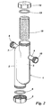
Figure 2 is a schematic 'exploded' view of the unit shown inFigure 1 . -
Figure 3 is a section view of the unit shown inFigures 1 and2 , but from a direct front view. - Referring to the Figures, the unit comprises a
housing 1 having afirst chamber 2 in communication with asecond chamber 3 by means of agap 4. The bottom of thefirst chamber 2 is closed by means of an easilyremovable screw cap 5 sealed into position by means of aseal 6. Thecap 5 may be conveniently provided with a transparent section to allow spot checks of the unit. Extending from the top of thefirst chamber 2 is aninlet pipe 7 provided with anexternal screw thread 8. Abaffle 14 is provided at the top of thefirst chamber 2. - Extending from the top of the
second chamber 3 is anoutlet pipe 9 provided with an external screw thread orpush fitting 10. Between the top of thefirst chamber 2 and thesecond chamber 3 is ahole 11. The top of thesecond chamber 3 is externally screw threaded and closed by means of an easily removable screw threadedcap 12 sealed into position by means of aseal 13. Thecap 12 may be optionally provided with a transparent section to allow spot checks of the unit. Solid particulate neutralising agent is held in a pliable sealedmesh bag 15 positioned below the level of theoutlet pipe 9 andhole 11. Themesh bag 15 is supported by aprotruding support fin 16 located in the hemispherical base of the chamber so that it will not settle or fit snugly into the base of the second chamber, thus keepinggap 4 free.
In normal use, the unit is connected to the boiler condensate outlet through theinlet pipe 7. Aliquots of condensate are expelled from the boiler (not shown) through theinlet pipe 7 into thefirst chamber 2.Baffle 14 prevents condensate from passing straight into thesecond chamber 3. The condensate collects at the bottom of thefirst chamber 2 until the next aliquot or batch of condensate enters the inlet pipe 7and pushes the condensate already collected at the bottom offirst chamber 2 through thegap 4 and into thesecond chamber 3. As each aliquot enters thefirst chamber 2 the condensate in thesecond chamber 3 is in turn forced through the solid neutralising agent in thesock 15 and is neutralised as it passes. The neutralised condensate exits thesecond chamber 3 through theoutlet pipe 9 to a drain (not shown). The design of the unit means that there is an air passage namelyoutlet 9, through the top region ofsecond chamber 3 above the neutralisingagent 15, throughhole 11, around baffle 14 and out throughinlet 7. This allows substantially continuous air flow through the unit without the air having to pass through the 'U' configuration of the first andsecond chambers agent 15. The aim of this feature is to allow air to flow upstream (i.e. towards the boiler) so as not to interfere with the siphoning action of the condensate discharge, even if there is a blockage in the unit. - In the event of blockage of the unit caused by any restriction to flow in either
first chamber 2 orsecond chamber 3, the geometry of the unit is so designed that condensate backs up infirst chamber 2 until it encounters an escape passage - hole 11 - at the top of the separating wall betweenfirst chamber 2 andsecond chamber 3 and can enter and then discharge as normal throughoutlet 9 from the top of second chamber 3 - but without having passed through the 'U' path of the unit and not through the neutralisingagent 15. Although the discharge from the unit would then be un-neutralised acidic condensate, there is no danger of interfering with the operation of the boiler, nor of condensate backing up to the boiler unit itself.
When it is necessary to replace the neutralizing agent this is simply done by unscrewing thecap 12, pulling out thebag 15 by means of a tag (not shown), inserting areplacement bag 15 containing fresh neutralising agent, and screwing thecap 12 back on. There is no need to disconnect theunit 1 from its connecting pipe work so the process is quick, clean and easy.
Claims (14)
- A neutralising unit suitable for attachment to the condensate outlet of a condensing boiler comprises a housing which has an inlet leading into a first chamber, a second chamber leading to an outlet, the second chamber containing a solid neutralising agent characterised in that the neutralising unit is adapted so that, in normal use, condensate from the boiler flows through the inlet (7) into the first chamber (2), then upwards through the solid neutralising agent (15) in the second chamber (3) and then out through the outlet (9).
- A neutralising unit according to claim 1 in which the unit is provided with an air passage which extends completely through the unit from the inlet to the outlet but without passing through the neutralising agent so that in normal use of the unit, air can pass from the outlet to the inlet without passing through the neutralising agent.
- A neutralising unit according to claim 1 or 2 in which the unit is provided with an escape passage at or near the top of the separating wall between first and second chambers so that in the event of blockage of the unit caused by any restriction to condensate flow in either first or second chamber, the condensate would pass through the escape passage and then discharge from the outlet of the second chamber without having passed through the neutralising agent.
- A neutralising unit according to claim 2 and 3 in which the air passage also functions as the escape passage.
- A neutralising unit according to any preceding claim in which the first chamber is provided with a barrier means to direct condensate into the first chamber.
- A neutralising unit according to claim 5 in which the barrier means comprises a baffle.
- A neutralising unit according to any preceding claim in which access means is provided at or near the top of the second chamber to allow removal/replacement of the neutralising agent.
- A neutralising unit according to any preceding claim in which the neutralising agent is in particulate form.
- A neutralising unit according to any preceding claim in which the neutralising agent is enclosed in a pliable container.
- A neutralising unit according to any preceding claim in which the neutralising agent is held so that it does not restrict the flow of condensate from the first chamber into the second chamber.
- A neutralising unit according to claim 10 in which the interior of the second chamber is provided with at least one protrusion to prevent the neutralising agent from settling into the bottom of the second chamber.
- A neutralising unit according to claim 11 in which the protrusion comprises at least one fin.
- A neutralising unit according to any preceding claim in which the first and second chambers approximate to the two limbs of a 'U' configuration.
- A neutralising unit according to any preceding claim in which the outlet is positioned lower than the inlet.
Applications Claiming Priority (1)
| Application Number | Priority Date | Filing Date | Title |
|---|---|---|---|
| GBGB0821908.1A GB0821908D0 (en) | 2008-12-01 | 2008-12-01 | Condensate unit |
Publications (3)
| Publication Number | Publication Date |
|---|---|
| EP2192358A2 true EP2192358A2 (en) | 2010-06-02 |
| EP2192358A3 EP2192358A3 (en) | 2014-03-19 |
| EP2192358B1 EP2192358B1 (en) | 2016-08-31 |
Family
ID=40262466
Family Applications (1)
| Application Number | Title | Priority Date | Filing Date |
|---|---|---|---|
| EP09252644.1A Active EP2192358B1 (en) | 2008-12-01 | 2009-11-18 | Condensate unit |
Country Status (2)
| Country | Link |
|---|---|
| EP (1) | EP2192358B1 (en) |
| GB (2) | GB0821908D0 (en) |
Cited By (2)
| Publication number | Priority date | Publication date | Assignee | Title |
|---|---|---|---|---|
| GB2483938A (en) * | 2010-09-27 | 2012-03-28 | Granville Newick | Anti-freezing unit for a condensing boiler |
| EP4015934A1 (en) * | 2020-12-21 | 2022-06-22 | Riello S.p.A. | Condensing boiler |
Families Citing this family (1)
| Publication number | Priority date | Publication date | Assignee | Title |
|---|---|---|---|---|
| GB0916842D0 (en) * | 2009-09-25 | 2009-11-04 | Fellows Timothy A | Condensate heater |
Family Cites Families (10)
| Publication number | Priority date | Publication date | Assignee | Title |
|---|---|---|---|---|
| DE3243988A1 (en) * | 1982-11-27 | 1984-05-30 | Fried. Krupp Gmbh, 4300 Essen | Gas-fired boiler installation |
| JPS6097094A (en) * | 1983-10-31 | 1985-05-30 | Matsushita Electric Ind Co Ltd | Neutralization processing equipment |
| DE3838701A1 (en) * | 1988-11-15 | 1990-08-09 | Bernhard Kessel | Apparatus for neutralizing liquids |
| JP4355974B2 (en) * | 1999-09-28 | 2009-11-04 | 株式会社ノーリツ | Neutralizer |
| JP2001300554A (en) * | 2000-04-26 | 2001-10-30 | Noritz Corp | Drain neutralizer |
| CN2851973Y (en) * | 2005-11-25 | 2006-12-27 | 广东万家乐燃气具有限公司 | Integrated condensed water treatment device for condensation type gas water heater |
| WO2009024126A1 (en) * | 2007-08-18 | 2009-02-26 | Freigeber Juergen | Apparatus for neutralizing acidic combustion condensates |
| KR200444631Y1 (en) * | 2007-10-04 | 2009-05-28 | 롯데알미늄 주식회사 | Water trap for boiler |
| CN201129868Y (en) * | 2007-11-15 | 2008-10-08 | 樱花卫厨(中国)有限公司 | Flue gas condensate water neutralization device for condensing gas water heater |
| DE102008019290A1 (en) * | 2008-04-16 | 2009-10-22 | Bomat Heiztechnik Gmbh | Neutralization device |
-
2008
- 2008-12-01 GB GBGB0821908.1A patent/GB0821908D0/en not_active Ceased
-
2009
- 2009-11-18 GB GB0920135.1A patent/GB2465662B/en active Active
- 2009-11-18 EP EP09252644.1A patent/EP2192358B1/en active Active
Non-Patent Citations (1)
| Title |
|---|
| None |
Cited By (3)
| Publication number | Priority date | Publication date | Assignee | Title |
|---|---|---|---|---|
| GB2483938A (en) * | 2010-09-27 | 2012-03-28 | Granville Newick | Anti-freezing unit for a condensing boiler |
| GB2483938B (en) * | 2010-09-27 | 2013-09-18 | Granville Newick | Anti-freezing unit |
| EP4015934A1 (en) * | 2020-12-21 | 2022-06-22 | Riello S.p.A. | Condensing boiler |
Also Published As
| Publication number | Publication date |
|---|---|
| GB2465662B (en) | 2013-08-14 |
| GB0821908D0 (en) | 2009-01-07 |
| EP2192358B1 (en) | 2016-08-31 |
| GB2465662A (en) | 2010-06-02 |
| GB0920135D0 (en) | 2009-12-30 |
| EP2192358A3 (en) | 2014-03-19 |
Similar Documents
| Publication | Publication Date | Title |
|---|---|---|
| US5203989A (en) | Portable air-water generator | |
| WO1992013623A1 (en) | Portable air-water generator | |
| US8899261B2 (en) | Trap apparatus for condensate water and drain apparatus for condensate water installed on the same | |
| US20220178583A1 (en) | Conduit fitting with integrated condensate trap | |
| GB2491361A (en) | Magnetic filter apparatus | |
| EP2192358B1 (en) | Condensate unit | |
| US20050198989A1 (en) | Dual p-trap and valve condensate collection and treatment system | |
| KR101738563B1 (en) | Device of Discharging Condensate of Double Pipe Flue | |
| EP2060539B1 (en) | Condensate treatment apparatus | |
| JP2006102617A (en) | Drain treatment apparatus and hot-water supply apparatus equipped with the same | |
| EP1734316B1 (en) | Condensing boiler assembly | |
| JP5741906B2 (en) | Water heater | |
| CA2831656A1 (en) | Device for neutralizing acid condensates | |
| KR100456397B1 (en) | Purification device for condensing boiler | |
| JP3837112B2 (en) | Water heater | |
| JP2009172535A (en) | Neutralization device and combustion apparatus equipped with the same | |
| JP7138371B2 (en) | Filter equipment and water heater | |
| CN210320207U (en) | Oil smoke separator and be equipped with its lampblack absorber | |
| KR20090003292U (en) | Water trap for boiler | |
| KR100731250B1 (en) | Particulate circulation exhaust gas cooling heat exchanger | |
| JP6341406B2 (en) | Through-wall combustion equipment | |
| CN201445863U (en) | A water separation device for a gas water heater condensing heat exchanger | |
| KR200279790Y1 (en) | The recycling device of waste heat | |
| KR200446568Y1 (en) | Water trap for boiler | |
| KR20110119437A (en) | Odor blocking device for sewage collecting |
Legal Events
| Date | Code | Title | Description |
|---|---|---|---|
| PUAI | Public reference made under article 153(3) epc to a published international application that has entered the european phase |
Free format text: ORIGINAL CODE: 0009012 |
|
| AK | Designated contracting states |
Kind code of ref document: A2 Designated state(s): AT BE BG CH CY CZ DE DK EE ES FI FR GB GR HR HU IE IS IT LI LT LU LV MC MK MT NL NO PL PT RO SE SI SK SM TR |
|
| AX | Request for extension of the european patent |
Extension state: AL BA RS |
|
| 17P | Request for examination filed |
Effective date: 20101027 |
|
| PUAL | Search report despatched |
Free format text: ORIGINAL CODE: 0009013 |
|
| AK | Designated contracting states |
Kind code of ref document: A3 Designated state(s): AT BE BG CH CY CZ DE DK EE ES FI FR GB GR HR HU IE IS IT LI LT LU LV MC MK MT NL NO PL PT RO SE SI SK SM TR |
|
| AX | Request for extension of the european patent |
Extension state: AL BA RS |
|
| RIC1 | Information provided on ipc code assigned before grant |
Ipc: C02F 1/66 20060101ALI20140212BHEP Ipc: F24H 8/00 20060101AFI20140212BHEP |
|
| 17Q | First examination report despatched |
Effective date: 20150707 |
|
| GRAP | Despatch of communication of intention to grant a patent |
Free format text: ORIGINAL CODE: EPIDOSNIGR1 |
|
| INTG | Intention to grant announced |
Effective date: 20151111 |
|
| RAP1 | Party data changed (applicant data changed or rights of an application transferred) |
Owner name: SENTINEL PERFORMANCE SOLUTIONS LTD |
|
| INTG | Intention to grant announced |
Effective date: 20160216 |
|
| GRAS | Grant fee paid |
Free format text: ORIGINAL CODE: EPIDOSNIGR3 |
|
| GRAA | (expected) grant |
Free format text: ORIGINAL CODE: 0009210 |
|
| AK | Designated contracting states |
Kind code of ref document: B1 Designated state(s): AT BE BG CH CY CZ DE DK EE ES FI FR GR HR HU IE IS IT LI LT LU LV MC MK MT NL NO PL PT RO SE SI SK SM TR |
|
| RBV | Designated contracting states (corrected) |
Designated state(s): AT BE BG CH CY CZ DE DK EE ES FI FR GR HR HU IE IS IT LI LT LU LV MC MK MT NL NO PL PT RO SE SI SK SM TR |
|
| REG | Reference to a national code |
Ref country code: CH Ref legal event code: EP |
|
| REG | Reference to a national code |
Ref country code: IE Ref legal event code: FG4D |
|
| REG | Reference to a national code |
Ref country code: AT Ref legal event code: REF Ref document number: 825349 Country of ref document: AT Kind code of ref document: T Effective date: 20161015 |
|
| REG | Reference to a national code |
Ref country code: DE Ref legal event code: R096 Ref document number: 602009040754 Country of ref document: DE |
|
| REG | Reference to a national code |
Ref country code: FR Ref legal event code: PLFP Year of fee payment: 8 |
|
| REG | Reference to a national code |
Ref country code: LT Ref legal event code: MG4D |
|
| REG | Reference to a national code |
Ref country code: NL Ref legal event code: MP Effective date: 20160831 |
|
| REG | Reference to a national code |
Ref country code: AT Ref legal event code: MK05 Ref document number: 825349 Country of ref document: AT Kind code of ref document: T Effective date: 20160831 |
|
| PG25 | Lapsed in a contracting state [announced via postgrant information from national office to epo] |
Ref country code: HR Free format text: LAPSE BECAUSE OF FAILURE TO SUBMIT A TRANSLATION OF THE DESCRIPTION OR TO PAY THE FEE WITHIN THE PRESCRIBED TIME-LIMIT Effective date: 20160831 Ref country code: NO Free format text: LAPSE BECAUSE OF FAILURE TO SUBMIT A TRANSLATION OF THE DESCRIPTION OR TO PAY THE FEE WITHIN THE PRESCRIBED TIME-LIMIT Effective date: 20161130 Ref country code: LT Free format text: LAPSE BECAUSE OF FAILURE TO SUBMIT A TRANSLATION OF THE DESCRIPTION OR TO PAY THE FEE WITHIN THE PRESCRIBED TIME-LIMIT Effective date: 20160831 Ref country code: FI Free format text: LAPSE BECAUSE OF FAILURE TO SUBMIT A TRANSLATION OF THE DESCRIPTION OR TO PAY THE FEE WITHIN THE PRESCRIBED TIME-LIMIT Effective date: 20160831 |
|
| PG25 | Lapsed in a contracting state [announced via postgrant information from national office to epo] |
Ref country code: NL Free format text: LAPSE BECAUSE OF FAILURE TO SUBMIT A TRANSLATION OF THE DESCRIPTION OR TO PAY THE FEE WITHIN THE PRESCRIBED TIME-LIMIT Effective date: 20160831 Ref country code: BE Free format text: LAPSE BECAUSE OF NON-PAYMENT OF DUE FEES Effective date: 20161130 Ref country code: GR Free format text: LAPSE BECAUSE OF FAILURE TO SUBMIT A TRANSLATION OF THE DESCRIPTION OR TO PAY THE FEE WITHIN THE PRESCRIBED TIME-LIMIT Effective date: 20161201 Ref country code: AT Free format text: LAPSE BECAUSE OF FAILURE TO SUBMIT A TRANSLATION OF THE DESCRIPTION OR TO PAY THE FEE WITHIN THE PRESCRIBED TIME-LIMIT Effective date: 20160831 Ref country code: ES Free format text: LAPSE BECAUSE OF FAILURE TO SUBMIT A TRANSLATION OF THE DESCRIPTION OR TO PAY THE FEE WITHIN THE PRESCRIBED TIME-LIMIT Effective date: 20160831 Ref country code: LV Free format text: LAPSE BECAUSE OF FAILURE TO SUBMIT A TRANSLATION OF THE DESCRIPTION OR TO PAY THE FEE WITHIN THE PRESCRIBED TIME-LIMIT Effective date: 20160831 Ref country code: SE Free format text: LAPSE BECAUSE OF FAILURE TO SUBMIT A TRANSLATION OF THE DESCRIPTION OR TO PAY THE FEE WITHIN THE PRESCRIBED TIME-LIMIT Effective date: 20160831 |
|
| PG25 | Lapsed in a contracting state [announced via postgrant information from national office to epo] |
Ref country code: RO Free format text: LAPSE BECAUSE OF FAILURE TO SUBMIT A TRANSLATION OF THE DESCRIPTION OR TO PAY THE FEE WITHIN THE PRESCRIBED TIME-LIMIT Effective date: 20160831 Ref country code: EE Free format text: LAPSE BECAUSE OF FAILURE TO SUBMIT A TRANSLATION OF THE DESCRIPTION OR TO PAY THE FEE WITHIN THE PRESCRIBED TIME-LIMIT Effective date: 20160831 |
|
| PG25 | Lapsed in a contracting state [announced via postgrant information from national office to epo] |
Ref country code: PT Free format text: LAPSE BECAUSE OF FAILURE TO SUBMIT A TRANSLATION OF THE DESCRIPTION OR TO PAY THE FEE WITHIN THE PRESCRIBED TIME-LIMIT Effective date: 20170102 Ref country code: CZ Free format text: LAPSE BECAUSE OF FAILURE TO SUBMIT A TRANSLATION OF THE DESCRIPTION OR TO PAY THE FEE WITHIN THE PRESCRIBED TIME-LIMIT Effective date: 20160831 Ref country code: DK Free format text: LAPSE BECAUSE OF FAILURE TO SUBMIT A TRANSLATION OF THE DESCRIPTION OR TO PAY THE FEE WITHIN THE PRESCRIBED TIME-LIMIT Effective date: 20160831 Ref country code: BE Free format text: LAPSE BECAUSE OF FAILURE TO SUBMIT A TRANSLATION OF THE DESCRIPTION OR TO PAY THE FEE WITHIN THE PRESCRIBED TIME-LIMIT Effective date: 20160831 Ref country code: BG Free format text: LAPSE BECAUSE OF FAILURE TO SUBMIT A TRANSLATION OF THE DESCRIPTION OR TO PAY THE FEE WITHIN THE PRESCRIBED TIME-LIMIT Effective date: 20161130 Ref country code: PL Free format text: LAPSE BECAUSE OF FAILURE TO SUBMIT A TRANSLATION OF THE DESCRIPTION OR TO PAY THE FEE WITHIN THE PRESCRIBED TIME-LIMIT Effective date: 20160831 Ref country code: SM Free format text: LAPSE BECAUSE OF FAILURE TO SUBMIT A TRANSLATION OF THE DESCRIPTION OR TO PAY THE FEE WITHIN THE PRESCRIBED TIME-LIMIT Effective date: 20160831 Ref country code: SK Free format text: LAPSE BECAUSE OF FAILURE TO SUBMIT A TRANSLATION OF THE DESCRIPTION OR TO PAY THE FEE WITHIN THE PRESCRIBED TIME-LIMIT Effective date: 20160831 |
|
| REG | Reference to a national code |
Ref country code: DE Ref legal event code: R097 Ref document number: 602009040754 Country of ref document: DE |
|
| REG | Reference to a national code |
Ref country code: CH Ref legal event code: PL |
|
| PLBE | No opposition filed within time limit |
Free format text: ORIGINAL CODE: 0009261 |
|
| STAA | Information on the status of an ep patent application or granted ep patent |
Free format text: STATUS: NO OPPOSITION FILED WITHIN TIME LIMIT |
|
| PG25 | Lapsed in a contracting state [announced via postgrant information from national office to epo] |
Ref country code: CH Free format text: LAPSE BECAUSE OF NON-PAYMENT OF DUE FEES Effective date: 20161130 Ref country code: LI Free format text: LAPSE BECAUSE OF NON-PAYMENT OF DUE FEES Effective date: 20161130 |
|
| 26N | No opposition filed |
Effective date: 20170601 |
|
| PG25 | Lapsed in a contracting state [announced via postgrant information from national office to epo] |
Ref country code: SI Free format text: LAPSE BECAUSE OF FAILURE TO SUBMIT A TRANSLATION OF THE DESCRIPTION OR TO PAY THE FEE WITHIN THE PRESCRIBED TIME-LIMIT Effective date: 20160831 |
|
| PG25 | Lapsed in a contracting state [announced via postgrant information from national office to epo] |
Ref country code: LU Free format text: LAPSE BECAUSE OF NON-PAYMENT OF DUE FEES Effective date: 20161130 |
|
| REG | Reference to a national code |
Ref country code: FR Ref legal event code: PLFP Year of fee payment: 9 |
|
| PG25 | Lapsed in a contracting state [announced via postgrant information from national office to epo] |
Ref country code: HU Free format text: LAPSE BECAUSE OF FAILURE TO SUBMIT A TRANSLATION OF THE DESCRIPTION OR TO PAY THE FEE WITHIN THE PRESCRIBED TIME-LIMIT; INVALID AB INITIO Effective date: 20091118 Ref country code: CY Free format text: LAPSE BECAUSE OF FAILURE TO SUBMIT A TRANSLATION OF THE DESCRIPTION OR TO PAY THE FEE WITHIN THE PRESCRIBED TIME-LIMIT Effective date: 20160831 |
|
| PG25 | Lapsed in a contracting state [announced via postgrant information from national office to epo] |
Ref country code: MK Free format text: LAPSE BECAUSE OF FAILURE TO SUBMIT A TRANSLATION OF THE DESCRIPTION OR TO PAY THE FEE WITHIN THE PRESCRIBED TIME-LIMIT Effective date: 20160831 Ref country code: IS Free format text: LAPSE BECAUSE OF FAILURE TO SUBMIT A TRANSLATION OF THE DESCRIPTION OR TO PAY THE FEE WITHIN THE PRESCRIBED TIME-LIMIT Effective date: 20160831 Ref country code: MC Free format text: LAPSE BECAUSE OF FAILURE TO SUBMIT A TRANSLATION OF THE DESCRIPTION OR TO PAY THE FEE WITHIN THE PRESCRIBED TIME-LIMIT Effective date: 20160831 |
|
| PG25 | Lapsed in a contracting state [announced via postgrant information from national office to epo] |
Ref country code: MT Free format text: LAPSE BECAUSE OF NON-PAYMENT OF DUE FEES Effective date: 20161118 |
|
| P01 | Opt-out of the competence of the unified patent court (upc) registered |
Free format text: CASE NUMBER: UPC_APP_326947/2023 Effective date: 20230524 |
|
| PGFP | Annual fee paid to national office [announced via postgrant information from national office to epo] |
Ref country code: DE Payment date: 20251119 Year of fee payment: 17 |
|
| PGFP | Annual fee paid to national office [announced via postgrant information from national office to epo] |
Ref country code: IT Payment date: 20251121 Year of fee payment: 17 |
|
| PGFP | Annual fee paid to national office [announced via postgrant information from national office to epo] |
Ref country code: FR Payment date: 20251121 Year of fee payment: 17 |
|
| PGFP | Annual fee paid to national office [announced via postgrant information from national office to epo] |
Ref country code: TR Payment date: 20251111 Year of fee payment: 17 |
|
| PGFP | Annual fee paid to national office [announced via postgrant information from national office to epo] |
Ref country code: IE Payment date: 20251121 Year of fee payment: 17 |