EP2192312A2 - A coupling bearing - Google Patents
A coupling bearing Download PDFInfo
- Publication number
- EP2192312A2 EP2192312A2 EP09156067A EP09156067A EP2192312A2 EP 2192312 A2 EP2192312 A2 EP 2192312A2 EP 09156067 A EP09156067 A EP 09156067A EP 09156067 A EP09156067 A EP 09156067A EP 2192312 A2 EP2192312 A2 EP 2192312A2
- Authority
- EP
- European Patent Office
- Prior art keywords
- insert
- ball
- housing
- thrust bearing
- outer ball
- Prior art date
- Legal status (The legal status is an assumption and is not a legal conclusion. Google has not performed a legal analysis and makes no representation as to the accuracy of the status listed.)
- Granted
Links
Images



Classifications
-
- F—MECHANICAL ENGINEERING; LIGHTING; HEATING; WEAPONS; BLASTING
- F16—ENGINEERING ELEMENTS AND UNITS; GENERAL MEASURES FOR PRODUCING AND MAINTAINING EFFECTIVE FUNCTIONING OF MACHINES OR INSTALLATIONS; THERMAL INSULATION IN GENERAL
- F16C—SHAFTS; FLEXIBLE SHAFTS; ELEMENTS OR CRANKSHAFT MECHANISMS; ROTARY BODIES OTHER THAN GEARING ELEMENTS; BEARINGS
- F16C11/00—Pivots; Pivotal connections
- F16C11/04—Pivotal connections
- F16C11/06—Ball-joints; Other joints having more than one degree of angular freedom, i.e. universal joints
- F16C11/0661—Ball-joints; Other joints having more than one degree of angular freedom, i.e. universal joints the two co-operative parts each having both convex and concave interfaces
-
- F—MECHANICAL ENGINEERING; LIGHTING; HEATING; WEAPONS; BLASTING
- F16—ENGINEERING ELEMENTS AND UNITS; GENERAL MEASURES FOR PRODUCING AND MAINTAINING EFFECTIVE FUNCTIONING OF MACHINES OR INSTALLATIONS; THERMAL INSULATION IN GENERAL
- F16C—SHAFTS; FLEXIBLE SHAFTS; ELEMENTS OR CRANKSHAFT MECHANISMS; ROTARY BODIES OTHER THAN GEARING ELEMENTS; BEARINGS
- F16C2326/00—Articles relating to transporting
- F16C2326/10—Railway vehicles
Definitions
- THE PRESENT INVENTION relates to a thrust bearing and more particularly to a thrust bearing for use as a tram and light rail coupling bearing.
- FIG. 1 of the accompanying drawings A conventional design for a thrust bearing (coupling bearing) for use in the coupling between a carriage and a bogie of a tram or similar light rail vehicle is shown in Figure 1 of the accompanying drawings.
- the upper part of the bearing is fixed to the carriage and the lower part of the bearing is fixed to the bogie under the carriage, allowing the bogie to rotate and pivot with respect to the carriage.
- This style of coupling bearing 1 comprises a generally cylindrical outer housing 2 having a circular base 3 having a central post 4 upstanding therefrom.
- the central post 4 is integrally formed with the base 3 of the housing 2.
- a spherical insert 5 is bonded to both the inside wall of the outer housing 2 and the top surface of the circular base 3.
- the spherical insert 5 presents a load-bearing surface in the form of a spherical bearing surface 6. Lubrication grooves may be provided to lubricate the load-bearing surface 6.
- the spherical insert 5 is manufactured from an engineering plastic.
- An outer ball 7 is seated on the spherical insert 5, an outer spherical counterface of the outer ball 7 having substantially the same radius as the load-bearing surface 6 of the spherical insert 5.
- the outer ball 7 is rotatably mounted on the spherical insert 5 such that it can accommodate rolling and pitching movements with respect to the outer housing 2.
- the outer ball 7 is manufactured from steel.
- the outer ball 7 has an inner spherical bearing surface 8.
- An inner ball 9 having a spherical bearing surface 10 is seated within the outer ball 7 on the inner bearing surface 8 of the outer ball 7, thereby sandwiching the outer ball 7 between the inner ball 9 and the spherical insert 5.
- the radius of the outer bearing surface 10 of the inner ball 9 substantially corresponds to the radius of the inner bearing surface 8 of the outer ball 7.
- the outer ball 7 is provided with fixing holes 11 which are equi-spaced around the top surface 12 of the outer ball 7.
- the fixing holes 11 are provided to allow the outer ball 7 to be fixedly attached to the carriage of a tram or similar vehicle.
- the inner ball 9 is formed generally as a truncated hemispheroid having two flat, substantially circular and parallel surfaces 13, 14.
- the inner ball 9 has a cylindrical recess 15 on the lower surface 14 in which a top cylindrical section 16 of the central post 4 is located.
- the outer ball 7 has a conical central aperture, through which the central post 4 protrudes, to be received by the cylindrical recess 15 of the inner ball 9.
- Five equi-spaced bores 17 are provided in the inner ball 9 which align with five threaded holes 18 provided in the post 4. Locking screws 19 pass through the bores 17 in the inner ball 9 and are screwed into the threaded holes 18 in the post 4.
- any fixing means e.g. bolt
- any fixing means used to fix a bogie to the base 3 of the housing 2 has the potential to work loose or break, become detached from the arrangement and drop through the bogie on to the track.
- the loss of the fixing means from the assembly would mean that the bogie and bearing 1 become readily separated, an occurrence which is preferably avoided in a crash situation.
- a thrust bearing comprising:
- the outer ball comprises a spherical outer surface, substantially conforming to the counterface of the first insert, the insert being of a substantially uniform thickness across the counterface.
- the first insert is bonded to the outer ball.
- the first insert is mechanically secured to the outer ball.
- the first insert is releasably mechanically secured to the outer ball.
- the first insert is provided with a thread
- the outer ball is provided with a corresponding thread, the first insert being screwed onto the outer ball to secure the first insert to the outer ball.
- the outer ball is an annulus having an at least partially threaded central aperture, the first insert being provided with a threaded hollow boss, which is screwed into the central aperture.
- the inner surface of the boss comprises a chamfered surface.
- the first insert is provided with at least one countersunk hole
- the outer ball is provided with a corresponding number of threaded holes, and at least one respective locking screw is fastened in the or each hole to secure the first insert to the outer ball, the head(s) of the locking screw(s) residing in the countersunk hole(s).
- the at least one recessed hole is provided on the counterface of the first insert.
- the thrust bearing comprises a second insert provided between the inner ball and outer ball.
- the second insert is secured to an inner surface of the outer ball.
- At least one of the first and second insert is either a self-lubricating or lubricated liner.
- the present invention further provides an outer ball having a spherical insert attached thereto, the spherical first insert presenting a counterface for interaction with a concave spherical bearing surface of a housing, the housing having a base, wherein a side wall and a central post are upstanding from the base, the central post being integrally formed with the outer housing; and a mounting arm is formed integrally with the housing, the outer ball for seating on and at least partially within the outer housing, to be sandwiched between the outer housing and an inner ball mounted on the central post.
- the thrust bearing 101 of Figures 2 and 3 comprises - in addition to the like-numbered features described above in relation to Figure 1 - a mounting arm 130 formed integrally with the bearing housing 102.
- the mounting arm 130 protrudes generally in a radially outwardly direction from the bearing housing 102.
- the mounting arm 130 comprises various fixing points 131 for fixing the thrust bearing 101 to a bogie of a vehicle.
- the mounting arm 130 shown in Figure 2 comprises at least one recess 132 on the underside of the mounting arm 130, to reduce the overall weight of the mounting arm 130.
- the at least one recess 132 may be defined by a number of strengthening webs provided in the underside of the mounting arm 130.
- the thrust bearing 101 further provides a bearing housing 102 and base 103 substantially of the same general structure as the housing 2 and base 3 of the known thrust bearing 1 shown in Figure 1 .
- the housing 102 of the thrust bearing 101 embodying the present invention provides a concave spherical bearing surface 140.
- the spherical bearing surface 140 may be seen as being dimensionally comparable to the bearing surface 6 of the insert 5 of the thrust bearing 1 in Figure 1 .
- the spherical bearing surface 140 is provided by the bearing housing 102 itself and not by a separate insert.
- the housing does not have a liner or insert.
- the bearing housing 102 of a thrust bearing 101 embodying the present invention is therefore a single, integral, item, with no sacrificial parts.
- the outer ball 107 is provided with a spherical first insert 141 attached to a spherical outer surface 142 of the outer ball 107.
- the first insert 141 presents a counterface 143 in sliding contact with the bearing surface 140 of the bearing housing 102.
- the bearing 101 may be disassembled and the insert 141 and/or the outer ball 107 replaced as necessary. It will be appreciated that it is far simpler, and cheaper, to replace the outer ball 107 than it is to replace the entire bearing housing 102 (with integral mounting arms 130). Further, there is then no need to remove the entire thrust bearing 101 from the vehicle and replacement of the outer ball 107 may be performed in the field.
- the first insert 141 is of substantially uniform thickness across its surface. As a result, the counterface 143 of the first insert 141 substantially conforms to the spherical outer surface 142 of the outer ball 107. The first insert 141 thus uses far less bearing material than the inert 5 of the thrust bearing 1 shown in Figure 1 .
- the first insert 141 is bonded to the outer spherical surface 142 of the outer ball 107.
- the first insert 141 is mechanically secured to the outer ball 107.
- the outer ball 207 is an annulus having an at least partially threaded central aperture 245.
- the first insert 241 is provided with a hollow boss 246.
- the outer surface 247 of the boss 246 is threaded, permitting the boss 246 to be screwed into the central aperture 245 of the outer ball 207.
- the inner surface 248 of the boss 246 comprises a conical surface, corresponding in function and form to the inner conical surface of the aperture of the outer ball 107 shown in Figures 2 and 3 .
- the diameter of the inner surface 248 of the boss 246 may the same as that of the aperture of the outer ball 107 of figures 2 and 3 .
- FIG. 5 An alternative embodiment is shown highly schematically in Figure 5 , wherein the first insert 341 is provided with at least one countersunk hole 349.
- a countersink recess 350 is provided co-axially with the hole 349 on the counterface 343.
- the outer ball 307 is provided with at least one respective threaded hole 351.
- the first insert 341 is attached to the outer ball 307 by securing a locking screw 352 through the hole 349 and into the threaded hole 351.
- the depth of the countersunk bore 350 is preferably more than the height of the head of the locking screw 352. As a result, when the locking screw 352 is secured in place, the screw head is recessed within the surface of the counterface 343 of the first insert 341.
- the first insert 341 is provided with a conical central aperture, the conical surface configured to correspond in function and form to the conical surface of the central aperture of the outer ball 307.
- the diameter of the conical central aperture may the same as that of the aperture of the outer ball 107 of figures 2 and 3 .
- the outer ball 7 is comprised of steel and the inner ball 9 is comprised of aluminium bronze. These materials have historically been chosen to facilitate pitch, swivel and rotational movement of the bearing surfaces. If the same material is used for both the inner and outer ball, galling will occur at the interface between the two balls.
- Weight considerations play a major part in designing thrust bearings and it is desirable to use lightweight aerospace type materials, such as titanium.
- both the inner 409 and outer 407 ball are manufactured from Titanium or an alloy thereof.
- a second insert 460 between the inner ball 409 and outer ball 407.
- the second insert 460 is secured to the inner surface 408 of the outer ball 407.
- the second insert 460 may be bonded to or mechanically secured to the inner surface 408 of the outer ball 407 in the same or similar ways to those as described above.
- the second insert 460 could be secured to the outer surface 410 of the inner ball 409.
- the inner ball 409 may be configured such that replacement is seldom necessary.
- first 141 and second inserts may be a self-lubricating liner, such as PTFE.
- the other, or both, of the first 141 and second insert may be a lubricated liner.
- the outer ball 107 may be removed and replaced.
- the inner ball 509 is configured so as to be moveable with respect to the central post 504. More specifically, the surface of the cylindrical recess 515 of the inner ball 509 slides translatably with respect to the top cylindrical section 516 of the central post 504. Between the top of the central post 504 and the inner ball 509 is disposed at least one shim 570. Four shims 570 are shown in the example of figure 7A . By removing at least one or all of the shims 570, the position of the inner ball 509 with respect to the central post 504 may be altered according to the user's requirements.
- the spherical bearing surface 510 of the inner ball 509 is moveable with respect to the spherical bearing surface 140 of the housing.
- the inner ball 509 is secured to the central post 504 using locking screws 19, (not shown) as in figures 2 , 3 and 6 .
- the arrangement is similar to that shown in figure 7A , but the central top portion of the post 604 is provided with a protruding cylindrical boss 671.
- the outer cylindrical surface of the boss 671 slides with respect to a cylindrical inner recess 672 of the inner ball 609.
- the shims 670 are ring-shaped, and are placed around the cylindrical boss 671. It will be noted that, by adding or removing the shims 670, the inner ball 609 may translate with respect to the post 604.
- a particular benefit of the arrangement shown in figure 7B , over 7A, is that it has improved radial stability.
- cylindrical boss 671 engages with the cylindrical inner recess surface 672 of the inner ball 609.
- cylindrical top section 616 of the central post 604 is always engaging with the cylindrical recess surface 615 of the inner ball 609.
Landscapes
- Engineering & Computer Science (AREA)
- General Engineering & Computer Science (AREA)
- Mechanical Engineering (AREA)
- Support Of The Bearing (AREA)
- Pivots And Pivotal Connections (AREA)
- Sliding-Contact Bearings (AREA)
Abstract
Description
- THE PRESENT INVENTION relates to a thrust bearing and more particularly to a thrust bearing for use as a tram and light rail coupling bearing.
- A conventional design for a thrust bearing (coupling bearing) for use in the coupling between a carriage and a bogie of a tram or similar light rail vehicle is shown in
Figure 1 of the accompanying drawings. The upper part of the bearing is fixed to the carriage and the lower part of the bearing is fixed to the bogie under the carriage, allowing the bogie to rotate and pivot with respect to the carriage. This style of coupling bearing 1 comprises a generally cylindricalouter housing 2 having a circular base 3 having acentral post 4 upstanding therefrom. Thecentral post 4 is integrally formed with the base 3 of thehousing 2. Aspherical insert 5 is bonded to both the inside wall of theouter housing 2 and the top surface of the circular base 3. Thespherical insert 5 presents a load-bearing surface in the form of a spherical bearingsurface 6. Lubrication grooves may be provided to lubricate the load-bearingsurface 6. Thespherical insert 5 is manufactured from an engineering plastic. - An outer ball 7 is seated on the
spherical insert 5, an outer spherical counterface of the outer ball 7 having substantially the same radius as the load-bearingsurface 6 of thespherical insert 5. The outer ball 7 is rotatably mounted on thespherical insert 5 such that it can accommodate rolling and pitching movements with respect to theouter housing 2. The outer ball 7 is manufactured from steel. - The outer ball 7 has an inner spherical bearing
surface 8. Aninner ball 9 having a spherical bearingsurface 10 is seated within the outer ball 7 on the inner bearingsurface 8 of the outer ball 7, thereby sandwiching the outer ball 7 between theinner ball 9 and thespherical insert 5. The radius of theouter bearing surface 10 of theinner ball 9 substantially corresponds to the radius of the inner bearingsurface 8 of the outer ball 7. - The outer ball 7 is provided with
fixing holes 11 which are equi-spaced around thetop surface 12 of the outer ball 7. Thefixing holes 11 are provided to allow the outer ball 7 to be fixedly attached to the carriage of a tram or similar vehicle. - The
inner ball 9 is formed generally as a truncated hemispheroid having two flat, substantially circular andparallel surfaces inner ball 9 has acylindrical recess 15 on thelower surface 14 in which a topcylindrical section 16 of thecentral post 4 is located. The outer ball 7 has a conical central aperture, through which thecentral post 4 protrudes, to be received by thecylindrical recess 15 of theinner ball 9. - Five equi-spaced
bores 17 are provided in theinner ball 9 which align with five threadedholes 18 provided in thepost 4. Lockingscrews 19 pass through thebores 17 in theinner ball 9 and are screwed into the threadedholes 18 in thepost 4. - To secure the
outer housing 2 of the bearing 1 to a bogie, access to the underside of the bogie is required, so that the bogie can be bolted to the underside of the base 3. It can be difficult to access the underside of a bogie "in the field" and thus the tram or light rail vehicle must be taken out of service and brought to a maintenance area having an inspection pit or other suitable provisions. Since such coupling bearings are often used in vehicles having low ground clearance, it is clearly undesirable to have to access the underside. - Still further, any fixing means (e.g. bolt) used to fix a bogie to the base 3 of the
housing 2 has the potential to work loose or break, become detached from the arrangement and drop through the bogie on to the track. Furthermore, the loss of the fixing means from the assembly would mean that the bogie and bearing 1 become readily separated, an occurrence which is preferably avoided in a crash situation. - In use, wear occurs to the
spherical insert 5 and theentire bearing housing 2, along with the adheredbearing insert 5, must then be removed from the vehicle and replaced. However, this requires undesirable access to the underside of the bearing, as discussed above. - It is an object of the present invention to provide a thrust bearing which overcome at least some of the disadvantages and problems associated with the bearing design discussed above.
- Accordingly, the present invention provides a thrust bearing comprising:
- a housing having a base, wherein a side wall and a central post are upstanding from the base, the central post being integrally formed with the outer housing; a mounting arm formed integrally with the housing ; the housing further comprising a concave spherical bearing surface;
- an outer ball seated on and at least partially within the outer housing, having a spherical first insert attached to the outer ball, the spherical first insert presenting a counterface in contact with the concave spherical bearing surface; and
- an inner ball mounted on the central post, wherein the outer ball is sandwiched between the inner ball and the outer housing.
- Preferably, the outer ball comprises a spherical outer surface, substantially conforming to the counterface of the first insert, the insert being of a substantially uniform thickness across the counterface.
- Conveniently, the first insert is bonded to the outer ball.
- Alternatively or additionally, the first insert is mechanically secured to the outer ball.
- Advantageously, the first insert is releasably mechanically secured to the outer ball.
- Preferably, the first insert is provided with a thread, and the outer ball is provided with a corresponding thread, the first insert being screwed onto the outer ball to secure the first insert to the outer ball.
- Conveniently, the outer ball is an annulus having an at least partially threaded central aperture, the first insert being provided with a threaded hollow boss, which is screwed into the central aperture.
- Advantageously, the inner surface of the boss comprises a chamfered surface.
- Preferably, the first insert is provided with at least one countersunk hole, and the outer ball is provided with a corresponding number of threaded holes, and at least one respective locking screw is fastened in the or each hole to secure the first insert to the outer ball, the head(s) of the locking screw(s) residing in the countersunk hole(s).
- Conveniently, the at least one recessed hole is provided on the counterface of the first insert.
- Advantageously, the thrust bearing comprises a second insert provided between the inner ball and outer ball.
- Preferably, the second insert is secured to an inner surface of the outer ball.
- Conveniently, at least one of the first and second insert is either a self-lubricating or lubricated liner.
- The present invention further provides an outer ball having a spherical insert attached thereto, the spherical first insert presenting a counterface for interaction with a concave spherical bearing surface of a housing, the housing having a base, wherein a side wall and a central post are upstanding from the base, the central post being integrally formed with the outer housing; and a mounting arm is formed integrally with the housing,
the outer ball for seating on and at least partially within the outer housing, to be sandwiched between the outer housing and an inner ball mounted on the central post. - In order that the present invention may be more readily understood, embodiments thereof will now be described, by way of example, with reference to the accompanying drawings, in which:
-
FIGURE 1 is a cross-section through a conventional thrust bearing for use as a coupling bearing between a carriage and a bogie; and -
FIGURE 2 shows a cross-section through a thrust bearing embodying the present invention; -
FIGURE 3 shows an enlarged view of the thrust bearing ofFigure 2 ; -
FIGURE 3B shows an enlarged section ofFigure 3A ; -
FIGURE 4 shows a schematic cross-section of part of another thrust bearing embodying the present invention; -
FIGURE 5 shows a schematic cross-section of part of another thrust bearing embodying the present invention; -
FIGURE 6A shows a cross-section of part of another thrust bearing embodying the present invention; -
FIGURE 6B shows an enlarged section ofFigure 6A ; and -
FIGURES 7A and 7B show a cross-section of part of another thrust bearing embodying the present invention. - The thrust bearing 101 of
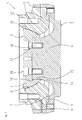
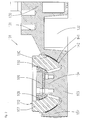
Figures 2 and3 , embodying the present invention, comprises - in addition to the like-numbered features described above in relation toFigure 1 - amounting arm 130 formed integrally with the bearinghousing 102. Themounting arm 130 protrudes generally in a radially outwardly direction from the bearinghousing 102. Themounting arm 130 comprisesvarious fixing points 131 for fixing the thrust bearing 101 to a bogie of a vehicle. Themounting arm 130 shown inFigure 2 comprises at least onerecess 132 on the underside of themounting arm 130, to reduce the overall weight of themounting arm 130. The at least onerecess 132 may be defined by a number of strengthening webs provided in the underside of themounting arm 130. - The thrust bearing 101 further provides a bearing
housing 102 andbase 103 substantially of the same general structure as thehousing 2 and base 3 of the known thrust bearing 1 shown inFigure 1 . In addition, thehousing 102 of the thrust bearing 101 embodying the present invention provides a concave spherical bearing surface 140. The spherical bearing surface 140 may be seen as being dimensionally comparable to thebearing surface 6 of theinsert 5 of the thrust bearing 1 inFigure 1 . In contrast, however, the spherical bearing surface 140 is provided by the bearinghousing 102 itself and not by a separate insert. The housing does not have a liner or insert. The bearinghousing 102 of athrust bearing 101 embodying the present invention is therefore a single, integral, item, with no sacrificial parts. - The
outer ball 107 is provided with a sphericalfirst insert 141 attached to a sphericalouter surface 142 of theouter ball 107. Thefirst insert 141 presents acounterface 143 in sliding contact with the bearing surface 140 of the bearinghousing 102. - When significant wear has occurred on the
first insert 141, thebearing 101 may be disassembled and theinsert 141 and/or theouter ball 107 replaced as necessary. It will be appreciated that it is far simpler, and cheaper, to replace theouter ball 107 than it is to replace the entire bearing housing 102 (with integral mounting arms 130). Further, there is then no need to remove the entire thrust bearing 101 from the vehicle and replacement of theouter ball 107 may be performed in the field. - It will be noted that the
first insert 141 is of substantially uniform thickness across its surface. As a result, thecounterface 143 of thefirst insert 141 substantially conforms to the sphericalouter surface 142 of theouter ball 107. Thefirst insert 141 thus uses far less bearing material than the inert 5 of the thrust bearing 1 shown inFigure 1 . - In the embodiment shown in
Figures 2 and3 , thefirst insert 141 is bonded to the outerspherical surface 142 of theouter ball 107. - In other embodiments, shown in
Figures 4 and5 , thefirst insert 141 is mechanically secured to theouter ball 107. - In the embodiment shown highly schematically in
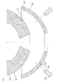
Figure 4 , theouter ball 207 is an annulus having an at least partially threadedcentral aperture 245. Thefirst insert 241 is provided with ahollow boss 246. Theouter surface 247 of theboss 246 is threaded, permitting theboss 246 to be screwed into thecentral aperture 245 of theouter ball 207. Theinner surface 248 of theboss 246 comprises a conical surface, corresponding in function and form to the inner conical surface of the aperture of theouter ball 107 shown inFigures 2 and3 . The diameter of theinner surface 248 of theboss 246 may the same as that of the aperture of theouter ball 107 offigures 2 and3 . - An alternative embodiment is shown highly schematically in
Figure 5 , wherein thefirst insert 341 is provided with at least onecountersunk hole 349. Acountersink recess 350 is provided co-axially with thehole 349 on thecounterface 343. Theouter ball 307 is provided with at least one respective threadedhole 351. Thefirst insert 341 is attached to theouter ball 307 by securing a lockingscrew 352 through thehole 349 and into the threadedhole 351. The depth of the countersunkbore 350 is preferably more than the height of the head of the lockingscrew 352. As a result, when the lockingscrew 352 is secured in place, the screw head is recessed within the surface of thecounterface 343 of thefirst insert 341. Thefirst insert 341 is provided with a conical central aperture, the conical surface configured to correspond in function and form to the conical surface of the central aperture of theouter ball 307. The diameter of the conical central aperture may the same as that of the aperture of theouter ball 107 offigures 2 and3 . - It will readily be appreciated that the features shown in both
Figures 4 and5 may be combined, to provide added security and to ensure that the first insert does not become separated from the outer ball. - With conventional thrust bearings, such as that shown in
Figure 1 , the outer ball 7 is comprised of steel and theinner ball 9 is comprised of aluminium bronze. These materials have historically been chosen to facilitate pitch, swivel and rotational movement of the bearing surfaces. If the same material is used for both the inner and outer ball, galling will occur at the interface between the two balls. - Weight considerations play a major part in designing thrust bearings and it is desirable to use lightweight aerospace type materials, such as titanium. The use of titanium - which is softer than steel and aluminium bronze - for both the inner and outer balls, however, promotes galling, pick-up, friction etc.
- In one embodiment of the present invention, as shown in
Figure 6 , both the inner 409 and outer 407 ball are manufactured from Titanium or an alloy thereof. There is provided asecond insert 460 between theinner ball 409 andouter ball 407. Thesecond insert 460 is secured to theinner surface 408 of theouter ball 407. Thesecond insert 460 may be bonded to or mechanically secured to theinner surface 408 of theouter ball 407 in the same or similar ways to those as described above. - Alternatively, the
second insert 460 could be secured to theouter surface 410 of theinner ball 409. However, it is preferable to provide thesecond insert 460 attached to theinner surface 408 of theouter ball 407, along with the first insert attached to the outer surface of the outer ball, since theouter ball 407 may therefore easily be replaced when significant wear has developed on the surfaces of either or both the first and second inserts. Theinner ball 409 may be configured such that replacement is seldom necessary. - Either or both of the first 141 and second inserts may be a self-lubricating liner, such as PTFE. The other, or both, of the first 141 and second insert may be a lubricated liner.
- As described above, when significant wear has occurred on either or both of the first 141 and second 460 inserts, the
outer ball 107 may be removed and replaced. - In a further embodiment of the present invention, a part of which is shown in
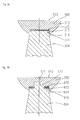
figure 7A , theinner ball 509 is configured so as to be moveable with respect to thecentral post 504. More specifically, the surface of thecylindrical recess 515 of theinner ball 509 slides translatably with respect to the topcylindrical section 516 of thecentral post 504. Between the top of thecentral post 504 and theinner ball 509 is disposed at least oneshim 570. Fourshims 570 are shown in the example offigure 7A . By removing at least one or all of theshims 570, the position of theinner ball 509 with respect to thecentral post 504 may be altered according to the user's requirements. As a convenient consequence, thespherical bearing surface 510 of theinner ball 509 is moveable with respect to the spherical bearing surface 140 of the housing. Theinner ball 509 is secured to thecentral post 504 using locking screws 19, (not shown) as infigures 2 ,3 and6 . - It will be appreciated that to add or remove a
shim 570, only theinner ball 509 needs to be removed. The outer ball 507 (not shown infigure 7A ) may remain in place. Only minimal maintenance is therefore required. - In another embodiment, a part of which is shown in
figure 7B , the arrangement is similar to that shown infigure 7A , but the central top portion of thepost 604 is provided with a protrudingcylindrical boss 671. The outer cylindrical surface of theboss 671 slides with respect to a cylindricalinner recess 672 of theinner ball 609. Theshims 670 are ring-shaped, and are placed around thecylindrical boss 671. It will be noted that, by adding or removing theshims 670, theinner ball 609 may translate with respect to thepost 604. A particular benefit of the arrangement shown infigure 7B , over 7A, is that it has improved radial stability. It will be noted that, at any one time, thecylindrical boss 671 engages with the cylindricalinner recess surface 672 of theinner ball 609. In addition, the cylindricaltop section 616 of thecentral post 604 is always engaging with thecylindrical recess surface 615 of theinner ball 609. - It will be appreciated from
figure 7B that smaller, disc-shapedshims 670 could alternatively, or additionally, be provided between theinner ball 609 and thecylindrical boss 671 of thepost 604. The ring-shapedshim 670 shown infigure 7B may not therefore be required. - When used in this specification and claims, the terms "comprises" and "comprising" and variations thereof mean that the specified features, steps or integers are included. The terms are not to be interpreted to exclude the presence of other features, steps or components.
- The features disclosed in the foregoing description, or the following claims, or the accompanying drawings, expressed in their specific forms or in terms of a means for performing the disclosed function, or a method or process for attaining the disclosed result, as appropriate, may, separately, or in any combination of such features, be utilised for realising the invention in diverse forms thereof.
Claims (15)
- A thrust bearing comprising:a housing having a base, wherein a side wall and a central post are upstanding from the base, the central post being integrally formed with the outer housing; a mounting arm formed integrally with the housing ; the housing further comprising a concave spherical bearing surface;an outer ball seated on and at least partially within the outer housing, having a spherical first insert attached to the outer ball, the spherical first insert presenting a counterface in contact with the concave spherical bearing surface; andan inner ball mounted on the central post, wherein the outer ball is sandwiched between the inner ball and the outer housing.
- A thrust bearing according to claim 1, wherein the outer ball comprises a spherical outer surface, substantially conforming to the counterface of the first insert, the insert being of a substantially uniform thickness across the counterface.
- A thrust bearing according to any preceding claim, wherein the first insert is bonded to the outer ball.
- A thrust bearing according to one of the claims 1 to 2, wherein the first insert is mechanically secured to the outer ball.
- A thrust bearing according to claim 4, wherein the first insert is releasably secured to the outer ball.
- A thrust bearing according to of claims 4 and 5, wherein the first insert is provided with a thread, and the outer ball is provided with a corresponding thread, the first insert being screwed onto the outer ball to secure the first insert to the outer ball.
- A thrust bearing according to claim 6, wherein the outer ball is an annulus having an at least partially threaded central aperture, the first insert being provided with a threaded hollow boss, which is screwed into the central aperture.
- A thrust bearing according to claim 7, wherein the inner surface of the boss comprises a chamfered surface.
- A thrust bearing according to one of the claims 4 to 8, wherein the first insert is provided with at least one countersunk hole, and the outer ball is provided with a corresponding number of threaded holes, and at least one respective locking screw is fastened in the or each hole to secure the first insert to the outer ball, the head(s) of the locking screw(s) residing in the countersunk hole(s).
- A thrust bearing according to claim 9, where the at least one recessed hole is provided on the counterface of the first insert.
- A thrust bearing according to any preceding claim, comprising a second insert provided between the inner ball and outer ball.
- A thrust bearing according to claim 11, wherein the second insert is secured to an inner surface of the outer ball.
- A thrust bearing according to any preceding claim, wherein at least one of the first and second insert is either a self-lubricating or lubricated liner.
- An outer ball having a spherical insert attached thereto, the spherical first insert presenting a counterface for interaction with a concave spherical bearing surface of a housing, the housing having a base, wherein a side wall and a central post are upstanding from the base, the central post being integrally formed with the outer housing; and a mounting arm is formed integrally with the housing,
the outer ball for seating on and at least partially within the outer housing, to be sandwiched between the outer housing and an inner ball mounted on the central post. - A thrust bearing substantially as hereinbefore described with reference to and as shown in the accompanying drawings.
Priority Applications (1)
| Application Number | Priority Date | Filing Date | Title |
|---|---|---|---|
| EP20090156067 EP2192312B1 (en) | 2008-11-26 | 2009-03-24 | A coupling bearing |
Applications Claiming Priority (2)
| Application Number | Priority Date | Filing Date | Title |
|---|---|---|---|
| EP08170032 | 2008-11-26 | ||
| EP20090156067 EP2192312B1 (en) | 2008-11-26 | 2009-03-24 | A coupling bearing |
Publications (3)
| Publication Number | Publication Date |
|---|---|
| EP2192312A2 true EP2192312A2 (en) | 2010-06-02 |
| EP2192312A3 EP2192312A3 (en) | 2012-04-04 |
| EP2192312B1 EP2192312B1 (en) | 2013-04-24 |
Family
ID=41719092
Family Applications (1)
| Application Number | Title | Priority Date | Filing Date |
|---|---|---|---|
| EP20090156067 Active EP2192312B1 (en) | 2008-11-26 | 2009-03-24 | A coupling bearing |
Country Status (1)
| Country | Link |
|---|---|
| EP (1) | EP2192312B1 (en) |
Cited By (4)
| Publication number | Priority date | Publication date | Assignee | Title |
|---|---|---|---|---|
| CN105114453A (en) * | 2015-07-28 | 2015-12-02 | 南车南京浦镇车辆有限公司 | Universal joint bearing with wear mark |
| CN107458408A (en) * | 2016-06-02 | 2017-12-12 | 株洲时代新材料科技股份有限公司 | Fixed hinge metal joint bearing and lower hold-down support attachment structure and attaching method thereof |
| CN107461404A (en) * | 2016-06-02 | 2017-12-12 | 株洲时代新材料科技股份有限公司 | Fixed hinge metal joint bearing and upper hold-down support attachment structure and attaching method thereof |
| CN107458411A (en) * | 2016-06-02 | 2017-12-12 | 株洲时代新材料科技股份有限公司 | A kind of low floor vehicle fixes hinge hinge method and fixed hinge articulated mounting |
Citations (2)
| Publication number | Priority date | Publication date | Assignee | Title |
|---|---|---|---|---|
| US4986688A (en) | 1990-04-16 | 1991-01-22 | Tuan C T | Structure of ball and socket joint for a vehicle steering control system |
| WO2008017095A1 (en) | 2006-08-10 | 2008-02-14 | Sattler, Erich | Spherical sliding insert for a bogie of a rail vehicle |
Family Cites Families (2)
| Publication number | Priority date | Publication date | Assignee | Title |
|---|---|---|---|---|
| DE3419776A1 (en) * | 1983-08-22 | 1985-03-14 | Ministerium für Verkehrswesen, DDR 1086 Berlin | Swivel ring for rail vehicles |
| DE10139970A1 (en) * | 2001-08-14 | 2003-02-27 | Ina Schaeffler Kg | Linking unit for two adjacent body structures of multiple body rail vehicles, comprises two concentrically nested spherical pivot bearings whose inner elements are joined to different body structures |
-
2009
- 2009-03-24 EP EP20090156067 patent/EP2192312B1/en active Active
Patent Citations (2)
| Publication number | Priority date | Publication date | Assignee | Title |
|---|---|---|---|---|
| US4986688A (en) | 1990-04-16 | 1991-01-22 | Tuan C T | Structure of ball and socket joint for a vehicle steering control system |
| WO2008017095A1 (en) | 2006-08-10 | 2008-02-14 | Sattler, Erich | Spherical sliding insert for a bogie of a rail vehicle |
Cited By (5)
| Publication number | Priority date | Publication date | Assignee | Title |
|---|---|---|---|---|
| CN105114453A (en) * | 2015-07-28 | 2015-12-02 | 南车南京浦镇车辆有限公司 | Universal joint bearing with wear mark |
| CN107458408A (en) * | 2016-06-02 | 2017-12-12 | 株洲时代新材料科技股份有限公司 | Fixed hinge metal joint bearing and lower hold-down support attachment structure and attaching method thereof |
| CN107461404A (en) * | 2016-06-02 | 2017-12-12 | 株洲时代新材料科技股份有限公司 | Fixed hinge metal joint bearing and upper hold-down support attachment structure and attaching method thereof |
| CN107458411A (en) * | 2016-06-02 | 2017-12-12 | 株洲时代新材料科技股份有限公司 | A kind of low floor vehicle fixes hinge hinge method and fixed hinge articulated mounting |
| DE102016118023B4 (en) | 2016-06-02 | 2024-02-01 | Zhuzhou Times New Material Technology Co., Ltd. | Connection method of a fixed hinge of a low-floor vehicle and fixed hinge connecting device |
Also Published As
| Publication number | Publication date |
|---|---|
| EP2192312A3 (en) | 2012-04-04 |
| EP2192312B1 (en) | 2013-04-24 |
Similar Documents
| Publication | Publication Date | Title |
|---|---|---|
| US6814493B2 (en) | Plain bearing and wind energy unit with said bearing | |
| EP2192312B1 (en) | A coupling bearing | |
| CN112943555B (en) | Shafting structure for wind generating set and wind generating set | |
| EP1983202B1 (en) | A thrust bearing | |
| ES2930173T3 (en) | Wind turbine comprising a yaw bearing system | |
| EP2548750B1 (en) | Thrust sliding bearing, and mechanism with this thrust sliding bearing combined with piston rod | |
| US12018641B2 (en) | Multi segment wind turbine blade joint bushing | |
| NL2030532B1 (en) | Adjustable levelling pad, system comprising a piece of machinery, a support and said adjustable pad, and assembly method of said system | |
| CA3138230A1 (en) | Swiveling hoist rings and methods of assembly | |
| CN105114446B (en) | Variable ladder damps thrust bearing | |
| JPH08510532A (en) | Body refraction vehicle and hinge assembly | |
| US6863115B2 (en) | Liquid-cooled mold for the continuous casting of metals | |
| EP1647725B1 (en) | Wear adjustable spherical thrust bearing arrangement for bi-directional axial loads for coupling a bogie to a passenger car | |
| AU2008221686B2 (en) | Bearing | |
| CN221347600U (en) | Joint bearing | |
| CN114427566B (en) | Rolling bearing and rotating device | |
| CN221170434U (en) | Thrust bearing cover | |
| GB2603142A (en) | Thrust bearing | |
| CN209838962U (en) | Improved bearing bush assembly | |
| CN213235810U (en) | Needle bearing retainer | |
| Li et al. | Frictional and wear performances and dynamic behaviors of carbon fiber-reinforced and graphite-modified crown-shaped polyetheretherketone ball-bearing cages | |
| DK201670168A1 (en) | Wind turbine comprising a yaw bearing system |
Legal Events
| Date | Code | Title | Description |
|---|---|---|---|
| PUAI | Public reference made under article 153(3) epc to a published international application that has entered the european phase |
Free format text: ORIGINAL CODE: 0009012 |
|
| AK | Designated contracting states |
Kind code of ref document: A2 Designated state(s): AT BE BG CH CY CZ DE DK EE ES FI FR GB GR HR HU IE IS IT LI LT LU LV MC MK MT NL NO PL PT RO SE SI SK TR |
|
| AX | Request for extension of the european patent |
Extension state: AL BA RS |
|
| PUAL | Search report despatched |
Free format text: ORIGINAL CODE: 0009013 |
|
| AK | Designated contracting states |
Kind code of ref document: A3 Designated state(s): AT BE BG CH CY CZ DE DK EE ES FI FR GB GR HR HU IE IS IT LI LT LU LV MC MK MT NL NO PL PT RO SE SI SK TR |
|
| AX | Request for extension of the european patent |
Extension state: AL BA RS |
|
| RIC1 | Information provided on ipc code assigned before grant |
Ipc: F16C 11/06 20060101AFI20120227BHEP |
|
| 17P | Request for examination filed |
Effective date: 20121001 |
|
| GRAP | Despatch of communication of intention to grant a patent |
Free format text: ORIGINAL CODE: EPIDOSNIGR1 |
|
| AKX | Designation fees paid |
Designated state(s): DE FR GB |
|
| GRAS | Grant fee paid |
Free format text: ORIGINAL CODE: EPIDOSNIGR3 |
|
| GRAA | (expected) grant |
Free format text: ORIGINAL CODE: 0009210 |
|
| AK | Designated contracting states |
Kind code of ref document: B1 Designated state(s): DE FR GB |
|
| REG | Reference to a national code |
Ref country code: GB Ref legal event code: FG4D |
|
| REG | Reference to a national code |
Ref country code: DE Ref legal event code: R096 Ref document number: 602009015143 Country of ref document: DE Effective date: 20130620 |
|
| PLBE | No opposition filed within time limit |
Free format text: ORIGINAL CODE: 0009261 |
|
| STAA | Information on the status of an ep patent application or granted ep patent |
Free format text: STATUS: NO OPPOSITION FILED WITHIN TIME LIMIT |
|
| 26N | No opposition filed |
Effective date: 20140127 |
|
| REG | Reference to a national code |
Ref country code: DE Ref legal event code: R097 Ref document number: 602009015143 Country of ref document: DE Effective date: 20140127 |
|
| REG | Reference to a national code |
Ref country code: FR Ref legal event code: PLFP Year of fee payment: 8 |
|
| REG | Reference to a national code |
Ref country code: FR Ref legal event code: PLFP Year of fee payment: 9 |
|
| REG | Reference to a national code |
Ref country code: DE Ref legal event code: R082 Ref document number: 602009015143 Country of ref document: DE Representative=s name: BOEHMERT & BOEHMERT ANWALTSPARTNERSCHAFT MBB -, DE Ref country code: DE Ref legal event code: R081 Ref document number: 602009015143 Country of ref document: DE Owner name: MINEBEA MITSUMI INC., JP Free format text: FORMER OWNER: MINEBEA CO., LTD., NAGANO, JP |
|
| REG | Reference to a national code |
Ref country code: FR Ref legal event code: PLFP Year of fee payment: 10 |
|
| PGFP | Annual fee paid to national office [announced via postgrant information from national office to epo] |
Ref country code: GB Payment date: 20260324 Year of fee payment: 18 |
|
| PGFP | Annual fee paid to national office [announced via postgrant information from national office to epo] |
Ref country code: DE Payment date: 20260331 Year of fee payment: 18 |
|
| PGFP | Annual fee paid to national office [announced via postgrant information from national office to epo] |
Ref country code: FR Payment date: 20260320 Year of fee payment: 18 |