EP2192302A1 - Compression mechanism and scroll compressor - Google Patents
Compression mechanism and scroll compressor Download PDFInfo
- Publication number
- EP2192302A1 EP2192302A1 EP08792185A EP08792185A EP2192302A1 EP 2192302 A1 EP2192302 A1 EP 2192302A1 EP 08792185 A EP08792185 A EP 08792185A EP 08792185 A EP08792185 A EP 08792185A EP 2192302 A1 EP2192302 A1 EP 2192302A1
- Authority
- EP
- European Patent Office
- Prior art keywords
- scroll
- compression mechanism
- mechanism according
- thickness
- movable
- Prior art date
- Legal status (The legal status is an assumption and is not a legal conclusion. Google has not performed a legal analysis and makes no representation as to the accuracy of the status listed.)
- Withdrawn
Links
- 230000006835 compression Effects 0.000 title claims abstract description 158
- 238000007906 compression Methods 0.000 title claims abstract description 158
- 238000000465 moulding Methods 0.000 claims abstract description 79
- 238000005266 casting Methods 0.000 claims abstract description 44
- 229910001060 Gray iron Inorganic materials 0.000 claims abstract description 40
- 239000003507 refrigerant Substances 0.000 claims abstract description 30
- 229910001018 Cast iron Inorganic materials 0.000 claims abstract description 29
- 238000004512 die casting Methods 0.000 claims abstract description 14
- OKTJSMMVPCPJKN-UHFFFAOYSA-N Carbon Chemical compound [C] OKTJSMMVPCPJKN-UHFFFAOYSA-N 0.000 claims description 30
- 229910002804 graphite Inorganic materials 0.000 claims description 30
- 239000010439 graphite Substances 0.000 claims description 30
- CURLTUGMZLYLDI-UHFFFAOYSA-N Carbon dioxide Chemical compound O=C=O CURLTUGMZLYLDI-UHFFFAOYSA-N 0.000 claims description 8
- 229910002092 carbon dioxide Inorganic materials 0.000 claims description 4
- 239000001569 carbon dioxide Substances 0.000 claims description 4
- 239000000463 material Substances 0.000 abstract description 11
- 230000007423 decrease Effects 0.000 description 16
- 238000005452 bending Methods 0.000 description 12
- 238000000034 method Methods 0.000 description 10
- 238000007730 finishing process Methods 0.000 description 7
- 238000007789 sealing Methods 0.000 description 4
- 230000000694 effects Effects 0.000 description 3
- 238000004519 manufacturing process Methods 0.000 description 3
- 238000009966 trimming Methods 0.000 description 3
- 230000003247 decreasing effect Effects 0.000 description 2
- 238000007788 roughening Methods 0.000 description 2
- 230000015556 catabolic process Effects 0.000 description 1
- 239000000203 mixture Substances 0.000 description 1
- 230000004048 modification Effects 0.000 description 1
- 238000012986 modification Methods 0.000 description 1
- 239000000341 volatile oil Substances 0.000 description 1
- 238000003466 welding Methods 0.000 description 1
Images







Classifications
-
- F—MECHANICAL ENGINEERING; LIGHTING; HEATING; WEAPONS; BLASTING
- F04—POSITIVE - DISPLACEMENT MACHINES FOR LIQUIDS; PUMPS FOR LIQUIDS OR ELASTIC FLUIDS
- F04C—ROTARY-PISTON, OR OSCILLATING-PISTON, POSITIVE-DISPLACEMENT MACHINES FOR LIQUIDS; ROTARY-PISTON, OR OSCILLATING-PISTON, POSITIVE-DISPLACEMENT PUMPS
- F04C18/00—Rotary-piston pumps specially adapted for elastic fluids
- F04C18/02—Rotary-piston pumps specially adapted for elastic fluids of arcuate-engagement type, i.e. with circular translatory movement of co-operating members, each member having the same number of teeth or tooth-equivalents
- F04C18/0207—Rotary-piston pumps specially adapted for elastic fluids of arcuate-engagement type, i.e. with circular translatory movement of co-operating members, each member having the same number of teeth or tooth-equivalents both members having co-operating elements in spiral form
- F04C18/0246—Details concerning the involute wraps or their base, e.g. geometry
- F04C18/0269—Details concerning the involute wraps
-
- B—PERFORMING OPERATIONS; TRANSPORTING
- B22—CASTING; POWDER METALLURGY
- B22D—CASTING OF METALS; CASTING OF OTHER SUBSTANCES BY THE SAME PROCESSES OR DEVICES
- B22D17/00—Pressure die casting or injection die casting, i.e. casting in which the metal is forced into a mould under high pressure
- B22D17/007—Semi-solid pressure die casting
-
- C—CHEMISTRY; METALLURGY
- C22—METALLURGY; FERROUS OR NON-FERROUS ALLOYS; TREATMENT OF ALLOYS OR NON-FERROUS METALS
- C22C—ALLOYS
- C22C1/00—Making non-ferrous alloys
- C22C1/02—Making non-ferrous alloys by melting
-
- F—MECHANICAL ENGINEERING; LIGHTING; HEATING; WEAPONS; BLASTING
- F04—POSITIVE - DISPLACEMENT MACHINES FOR LIQUIDS; PUMPS FOR LIQUIDS OR ELASTIC FLUIDS
- F04C—ROTARY-PISTON, OR OSCILLATING-PISTON, POSITIVE-DISPLACEMENT MACHINES FOR LIQUIDS; ROTARY-PISTON, OR OSCILLATING-PISTON, POSITIVE-DISPLACEMENT PUMPS
- F04C18/00—Rotary-piston pumps specially adapted for elastic fluids
- F04C18/02—Rotary-piston pumps specially adapted for elastic fluids of arcuate-engagement type, i.e. with circular translatory movement of co-operating members, each member having the same number of teeth or tooth-equivalents
- F04C18/0207—Rotary-piston pumps specially adapted for elastic fluids of arcuate-engagement type, i.e. with circular translatory movement of co-operating members, each member having the same number of teeth or tooth-equivalents both members having co-operating elements in spiral form
- F04C18/0246—Details concerning the involute wraps or their base, e.g. geometry
- F04C18/0253—Details concerning the base
- F04C18/0261—Details of the ports, e.g. location, number, geometry
-
- F—MECHANICAL ENGINEERING; LIGHTING; HEATING; WEAPONS; BLASTING
- F04—POSITIVE - DISPLACEMENT MACHINES FOR LIQUIDS; PUMPS FOR LIQUIDS OR ELASTIC FLUIDS
- F04C—ROTARY-PISTON, OR OSCILLATING-PISTON, POSITIVE-DISPLACEMENT MACHINES FOR LIQUIDS; ROTARY-PISTON, OR OSCILLATING-PISTON, POSITIVE-DISPLACEMENT PUMPS
- F04C23/00—Combinations of two or more pumps, each being of rotary-piston or oscillating-piston type, specially adapted for elastic fluids; Pumping installations specially adapted for elastic fluids; Multi-stage pumps specially adapted for elastic fluids
- F04C23/008—Hermetic pumps
-
- F—MECHANICAL ENGINEERING; LIGHTING; HEATING; WEAPONS; BLASTING
- F04—POSITIVE - DISPLACEMENT MACHINES FOR LIQUIDS; PUMPS FOR LIQUIDS OR ELASTIC FLUIDS
- F04C—ROTARY-PISTON, OR OSCILLATING-PISTON, POSITIVE-DISPLACEMENT MACHINES FOR LIQUIDS; ROTARY-PISTON, OR OSCILLATING-PISTON, POSITIVE-DISPLACEMENT PUMPS
- F04C2210/00—Fluid
- F04C2210/10—Fluid working
- F04C2210/1027—CO2
-
- F—MECHANICAL ENGINEERING; LIGHTING; HEATING; WEAPONS; BLASTING
- F04—POSITIVE - DISPLACEMENT MACHINES FOR LIQUIDS; PUMPS FOR LIQUIDS OR ELASTIC FLUIDS
- F04C—ROTARY-PISTON, OR OSCILLATING-PISTON, POSITIVE-DISPLACEMENT MACHINES FOR LIQUIDS; ROTARY-PISTON, OR OSCILLATING-PISTON, POSITIVE-DISPLACEMENT PUMPS
- F04C2210/00—Fluid
- F04C2210/10—Fluid working
- F04C2210/1072—Oxygen (O2)
-
- F—MECHANICAL ENGINEERING; LIGHTING; HEATING; WEAPONS; BLASTING
- F04—POSITIVE - DISPLACEMENT MACHINES FOR LIQUIDS; PUMPS FOR LIQUIDS OR ELASTIC FLUIDS
- F04C—ROTARY-PISTON, OR OSCILLATING-PISTON, POSITIVE-DISPLACEMENT MACHINES FOR LIQUIDS; ROTARY-PISTON, OR OSCILLATING-PISTON, POSITIVE-DISPLACEMENT PUMPS
- F04C2230/00—Manufacture
- F04C2230/20—Manufacture essentially without removing material
- F04C2230/21—Manufacture essentially without removing material by casting
-
- F—MECHANICAL ENGINEERING; LIGHTING; HEATING; WEAPONS; BLASTING
- F05—INDEXING SCHEMES RELATING TO ENGINES OR PUMPS IN VARIOUS SUBCLASSES OF CLASSES F01-F04
- F05C—INDEXING SCHEME RELATING TO MATERIALS, MATERIAL PROPERTIES OR MATERIAL CHARACTERISTICS FOR MACHINES, ENGINES OR PUMPS OTHER THAN NON-POSITIVE-DISPLACEMENT MACHINES OR ENGINES
- F05C2201/00—Metals
- F05C2201/04—Heavy metals
- F05C2201/0433—Iron group; Ferrous alloys, e.g. steel
- F05C2201/0436—Iron
- F05C2201/0439—Cast iron
Definitions
- the present invention relates to a compression mechanism and a scroll compressor including the compression mechanism. Particularly, the present invention relates to materials used in the compression mechanism.
- a scroll compressor includes a compression mechanism to compress refrigerant.
- the compression mechanism includes a fixed scroll and a movable scroll.
- Each of the two scrolls has a scroll portion which extends in an involute shape. The two scroll portions engage with each other.
- the fixed scroll has been formed of the same material as the movable scroll.
- Some examples of the materials are a grey iron casting, a cast iron molding fabricated through semi-molten die casting, and so forth.
- Patent Document 1 discloses the related art to the present invention.
- the compression mechanism will have low strength and low stiffness.
- the scrolls need to have their involute scroll portions thinner and longer in height.
- low strength and low stiffness of the compression mechanism can cause deformation or rupture of the involute scroll portions during operation. This problem will become significant when the scrolls are grey iron castings.
- the present invention solves the above problems.
- the present invention has an object to increase strength and stiffness of a compression mechanism and to prevent seizing thereof simultaneously.
- a compression mechanism is used in a scroll compressor, and includes a fixed scroll and a movable scroll.
- One of the two scrolls is a cast iron molding fabricated through semi-molten die casting, and the other is a grey iron casting.
- a compression mechanism according to a second aspect of the present invention is the compression mechanism according to the first aspect of the present invention, wherein the sum of a graphite area ratio on the surface of the cast iron molding and a graphite area ratio on the surface of the grey iron casting is greater than or equal to 10% and less than or equal to 20%.
- a compression mechanism according to a third aspect of the present invention is the compression mechanism according to the second aspect of the present invention, wherein the graphite area ratio on the surface of the cast iron molding is greater than or equal to 2% and less than or equal to 6%.
- a compression mechanism according to a fourth aspect of the present invention is the compression mechanism according to any one of the first to third aspects of the present invention, wherein a tensile strength of the grey iron casting is greater than or equal to 250N/mm 2 and less than 300N/mm 2 .
- a compression mechanism according to a fifth aspect of the present invention is the compression mechanism according to any one of the first to forth aspects of the present invention, wherein the fixed scroll is the grey iron casting, and the movable scroll is the cast iron molding.
- a compression mechanism according to a sixth aspect of the present invention is the compression mechanism according to the fifth aspect of the present invention, wherein the movable scroll is placed and pushed against the fixed scroll.
- a compression mechanism is the compression mechanism according to the fifth or sixth aspect of the present invention, wherein the fixed scroll has a first scroll portion and a first plate portion, and the movable scroll has a second scroll portion and a second plate portion.
- the first and second scroll portions extend in involute shapes.
- the first scroll portion engages with the second scroll portion.
- the first and second plate portions hold the first and second scroll portions respectively.
- the first plate portion has a through hole which connects a first space and a second space.
- the first space has an involute shape defined by the first scroll portion.
- the second space is located on the opposite side of the movable scroll.
- the second scroll portion is arranged to cover an opening of the through hole. The opening is located on the side of the first space.
- a compression mechanism according to an eighth aspect of the present invention is the compression mechanism according to the seventh aspect of the present invention, wherein the first scroll portion covers a portion of the opening of the through hole, as viewed from the side of the movable scroll.
- a compression mechanism is the compression mechanism according to any one of the fifth to eighth aspects of the present invention, wherein the fixed scroll has a first scroll portion, and the movable scroll has a second scroll portion.
- the first and second scroll portions extend in involute shapes.
- the first scroll portion engages with the second scroll portion.
- the movable scroll has an extended portion which extends from the end of the outmost wall of the second scroll portion. The extended portion does not engage with the first scroll portion.
- a compression mechanism is the compression mechanism according to any one of the first to ninth aspects of the present invention, wherein the fixed scroll has a first scroll portion, and the movable scroll has a second scroll portion.
- the first and second scroll portions extend in involute shapes.
- the first scroll portion engages with the second scroll portion.
- a thickness ratio of a first thickness to a second thickness is equal to a value calculated based on a Young's modulus ratio of the Young's modulus of the cast iron molding to the Young's modulus of the grey iron casting.
- the first thickness is the thickness of the first or second scroll portion of the cast iron molding
- the second thickness is the thickness of the first or second scroll portion of the grey iron casting.
- a compression mechanism according to an eleventh aspect of the present invention is the compression mechanism according to the tenth aspect of the present invention, wherein the thickness ratio is less than or equal to the reciprocal of the Young's modulus ratio.
- a compression mechanism according to a twelfth aspect of the present invention is the compression mechanism according to the tenth or eleventh aspect of the present invention, wherein the Young's modulus of the cast iron molding is 175GPa or more and 190GPa or less.
- a scroll compressor according to a thirteenth aspect of the present invention includes the compression mechanism according to any one of the first to twelfth aspects of the present invention.
- a scroll compressor according to a fourteenth aspect of the present invention is the scroll compressor according to the thirteenth aspect of the present invention, wherein the scroll compressor compresses refrigerant composed mostly of carbon dioxide
- the compression mechanism according to the first aspect has a fixed scroll and a movable scroll.
- One of the two scrolls is a cast iron molding fabricated through semi-molten die casting, while the other is a grey iron casting. Therefore, in this compression mechanism, seizing does not occur frequently between the fixed scroll and the movable scroll, unlike in a compression mechanism which includes a fixed scroll and a movable scroll, both of which are cast iron moldings fabricated through semi-molten die casting.
- the compression mechanism of the present invention can have thinner scroll portions, unlike a compression mechanism which includes a fixed scroll and a movable scroll, both of which are grey iron castings. This is because a cast iron molding fabricated through semi-molten die casting has higher strength and higher stiffness than a grey iron casting. Therefore, this compression mechanism can be downsized and maintain its intake capacity simultaneously. This compression mechanism can also keep its size unchanged and achieve higher intake capacity simultaneously.
- this compression mechanism can prevent deformation thereof caused by compression pressure. This is because a cast iron molding fabricated through semi-molten die casting has higher stiffness than a grey iron casting. Therefore, compressed refrigerant hardly leaks out of this compression mechanism, which prevents a decrease of the compression efficiency.
- the compression mechanism according to the second aspect has a large sum of the graphite area ratios, which can easily prevent seizing between the fixed scroll and the movable scroll.
- the compression mechanism according to the third aspect can secure the graphite area ratio on the surface of the cast iron molding, which is sufficient to prevent seizing.
- This compression mechanism can easily prevent seizing between the fixed scroll and the movable scroll.
- the compression mechanism according to the fourth aspect can have the strength and the stiffness sufficient to prevent deformation or rupture of this compression mechanism.
- the compression mechanism according to the fifth aspect can have thinner scroll portions, unlike a compression mechanism which includes a fixed scroll and a movable scroll, both of which are grey iron castings. This is because a cast iron molding fabricated through semi-molten die casting has higher strength and higher stiffness than a grey iron casting. Therefore, this compression mechanism can be downsized and maintain its intake capacity simultaneously. This compression mechanism can also keep its size unchanged and achieve higher intake capacity simultaneously.
- the movable scroll can be lightweight, which reduces torque required to operate the movable scroll.
- the cast iron molding fabricated through semi-molten die casting can reduce the cost of this compression mechanism.
- the compression mechanism according to the sixth aspect can prevent a gap between the scroll portion of the fixed scroll and that of the movable scroll, whereby prevents the decrease of the compression efficiency.
- the movable scroll is unlikely to deform when pushed against the fixed scroll. This is because the movable scroll is the cast iron molding fabricated through semi-molten die casting which has high strength and high stiffness.
- the compression mechanism according to the seventh aspect can prevent the decrease of the compression efficiency. This is because the through hole does not connect the first spaces on two sides of the scroll portion of the movable scroll, when the scroll portion of the movable scroll passes by an opening of the through hole. More specifically, in this case, the first spaces defined by the scroll portion do not connect to each other via the through hole.
- the compression mechanism according to the eighth aspect has an opening of the through hole on the side of the second space, and this opening can be bigger than an opening on the side of the first space. Therefore, compressed refrigerant can pass through the through hole more efficiently.
- the compression mechanism according to the ninth aspect has the movable scroll with the extended portion, which increases strength and stiffness of the end of the outmost wall of the movable scroll. Therefore, the extended portion prevents deformation of the outmost wall of the movable scroll during fabrication.
- the compression mechanism according to the tenth aspect can have substantially equal amounts of bending between the two scroll portions, wherein one of the scroll portions is a cast iron molding fabricated through semi-molten die casting, while the other is a grey iron casting. This is because the thickness ratio of the scroll portions is calculated based on the Young's modulus ratio of the scroll portions.
- the compression mechanism can prevent the decrease of the compression efficiency due to the bending of the scroll portions.
- the compression mechanism according to the eleventh aspect can be downsized. This is because a scroll portion of the cast iron molding can be made thinner.
- the compression mechanism according to the twelfth aspect can prevent the decrease of the compression efficiency due to the bending of the cast iron molding.
- the scroll compressor according to the thirteenth aspect can prevent seizing between the fixed scroll and the movable scroll of the compression mechanism. Therefore, the scroll compressor is less prone to breakdown.
- the scroll compressor according to the fourteenth aspect can improve the compression efficiency, even when carbon dioxide is used as refrigerant.
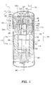
- FIG 1 shows a schematic view of a scroll compressor 1 according to an embodiment of the present invention.
- the upper side is defined as a side pointed by an arrow 91 shown in FIG 1
- the lower side is defined as the opposite side to the upper side.
- the scroll compressor 1 includes a casing 11 and a compression mechanism 15.
- the casing 11 is a cylindrical body elongated along the arrow 91.
- the compression mechanism 15 is disposed inside the casing 11.
- FIG 2 shows a cross-sectional view of the compression mechanism 15 along the line II-II shown in FIG 1 .
- the compression mechanism 15 includes a fixed scroll 24 and a movable scroll 26 (See FIG 1 and FIG 2 ).
- the compression mechanism 15 compresses refrigerant.
- An example of the refrigerant is composed mostly of carbon dioxide.
- the fixed scroll 24 includes a first plate portion 24a and a first scroll portion 24b.
- the first plate portion 24a is secured to an inner wall 11 a of the casing 11.
- the first scroll portion 24b is attached to the lower side of the first plate portion 24a (See FIG 1 ).
- the first scroll portion 24b extends in an involute shape, and forms a spiral channel 24c between its involuted walls (See FIG 2 ).
- the first plate portion 24a is a fixing member which holds the first scroll portion 24b.
- the movable scroll 26 includes a second plate portion 26a and a second scroll portion 26b.
- the second scroll portion 26b is attached to the upper side of the second plate portion 26a (See FIG 1 ).
- the second scroll portion 26b extends in an involute shape (See FIG 2 ).
- the second plate portion 26a is another fixing member which holds the second scroll portion 26b.
- the second scroll portion 26b fits in the spiral channel 24c of the fixed scroll 24 (See FIG 2 ).
- the compression mechanism 15 has a compression space 40 between the first scroll portion 24b and the second scroll portion 26b.
- the compression space 40 is confined by the first plate portion 24a and the second plate portion 26a, and is used as a compression chamber which compresses refrigerant (See FIG. 1 ).
- first to third embodiments of the present invention describe respectively materials used for the fixed scroll 24 and the movable scroll 26, configurations of the first scroll portion 24b and the second scroll portion 26b, and a relief hole in the fixed scroll 24.
- a material used for the fixed scroll 24 is different from that for the movable scroll 26.
- one of the fixed scroll 24 and the movable scroll 26 is a cast iron molding fabricated through semi-molten die casting (hereinafter, this molding is called "semi-molten die cast molding").
- the semi-molten die cast molding has a tensile strength of greater than or equal to 600N/mm 2 and less than or equal to 900N/mm 2 .
- the other one of the fixed scroll 24 and the movable scroll 26 is a grey iron casting.
- the grey iron casting has a tensile strength of greater than or equal to 250N/mm 2 and less than 300N/mm 2 .
- the tensile strength can ensure sufficient strength and stiffness of the grey iron casting to prevent deformation or rupture thereof.
- JIS Japanese Industrial Standards
- a grey iron casting that has a tensile strength of greater than or equal to 250N/mm 2 and less than 300N/mm 2 is a FC250.
- FIG 3 is a table showing surface pressure for seizing to occur (MPa), graphite area ratio (%), and hardness (HRB) of the compression mechanism 15.
- the surface pressure for seizing to occur represents the pressure which causes seizing to occur during a seizing test.
- the seizing test is implemented by sliding a pin-shaped molding (hereinafter, this molding is called “pin”) on the surface of a disk-shaped molding (hereinafter, this molding is called “disk”) based on a predetermined method.
- the predetermined method is as follows: soak a disk and a pin in a mixture of refrigerant R410A and ethereal oil (at 100 degrees centigrade); slide the pin at an average speed of 2.0m/s; change a surface pressure between the pin and the disk; observe whether or not seizing occurs between the pin and the disk to measure the surface pressure which causes seizing to occur between the pin and the disk.
- the graphite area ratio represents an area occupied by graphite per unit area of the compression mechanism 15.
- “slider A” is one of the fixed scroll 24 and the movable scroll 26, while “slider B” is the other.
- the graphite area ratio (%) and the hardness (HRB) of each of the slider A and B are shown respectively in FIG 3 .
- HRB hardness
- a sum of the graphite area ratio of each of the slider A and B is called “total graphite area ratio” which is shown in the table of FIG 3 (See the column “slider A + slider B").
- FIG 3 shows a seizing test result between a pin-shaped semi-molten die cast molding and a disk-shaped grey iron casting (See the row “semi-molten die cast molding/FC250").
- FIG. 3 also shows seizing test results for pins and disks made of the same materials. More specifically, FIG 3 shows a seizing test result between a pin-shaped grey iron casting (FC250) and a disk-shaped grey iron casting (FC250) (See the row "FC250s”), and a seizing test result between a pin-shaped semi-molten die cast molding and a disk-shaped semi-molten die cast molding (See the row "semi-molten die cast moldings").
- the "semi-molten die cast molding/FC250" test result is as follows: the surface pressure for seizing to occur is 152MPa; the total graphite area ratio is 10% to 20%; the graphite area ratio of the slider A is 2% to 6%; the graphite area ratio of the slider B is 8% to 14%; the hardness of the slider A is HRB90 to HRB100; and the hardness of the slider B is HRB90 to HRB100.
- the slider A is the semi-molten die cast molding
- the slider B is the grey iron casting (FC250).
- the "FC250s" test result is as follows: the surface pressure for seizing to occur is 169MPa; the total graphite area ratio is 28%; the graphite area ratios of the slider A and slider B are both 14%; the hardness of the slider A and slider B are both HRB93.
- the "semi-molten die cast moldings" test result is as follows: the surface pressure for seizing to occur is 140MPa; the total graphite area ratio is 8%; the graphite area ratios of the slider A and slider B are both 4.0%; the hardness of the slider A and slider B are both HRB98.
- FIG 3 shows that the surface pressure for seizing to occur in the "semi-molten die cast molding/FC250" test is higher than that in the "semi-molten die cast moldings” test. The reason is presented as follows.
- FIG 4 is a graph showing the relationship between the total graphite area ratio and the surface pressure for seizing to occur.
- FIG 4 suggests that a higher total graphite area ratio results in a higher surface pressure for seizing to occur. Accordingly, because the total graphite area ratio in the "semi-molten die cast molding/FC250" test is higher than that in the "semi-molten die cast moldings" test, their surface pressures for seizing to occur also show a similar trend.
- the "semi-molten die cast molding/FC250" test shows that the graphite area ratio of the grey iron casting (FC250) is 8% to 14% which is notably higher than that of the semi-molten die cast molding, 2% to 6%.
- the remarkable difference of the graphite area ratio between the pin and the disk will be one of the factors that result in the increase of the surface pressure for seizing.
- the semi-molten die cast molding needs to have a graphite area ratio of at least 2% in order to prevent seizing.
- the compression mechanism 15 can easily prevent seizing between the fixed scroll 24 and the movable scroll 26, compared to a compression mechanism which includes a fixed scroll and a movable scroll, both of which are semi-molten die cast moldings.
- the compression mechanism 15 has a higher hardness, higher strength, and higher stiffness than a compression mechanism which includes a fixed scroll and a movable scroll, both of which are grey iron castings (FC250). Therefore, either the fixed scroll 24 or the movable scroll 26, whichever is the semi-molten die cast molding, can have the smaller thickness d2 (or d1) of the scroll portion 26b (or 24b) (See FIG.2 ), and have the scroll portion 26b (or 24b) longer in height.
- This scroll results in downsizing the compression mechanism 15 without decreasing the compression efficiency.
- This scroll also results in increasing the intake capacity without changing the size of the compression mechanism 15.
- the graphite area ratio of the semi-molten die cast molding is preferably 4% to 6%. This is because the material workability of the semi-molten die cast molding will improve, due to the hardness thereof which can get near to HRB90 (more specifically, HRB90 to HRB95).
- the fixed scroll 24 is preferably the grey iron casting (FC250) and the movable scroll 26 is preferably the semi-molten die cast molding.
- the movable scroll 26 of the semi-molten die cast molding can have the thinner second scroll portion 26b and the thinner second plate portion 26a.
- the compression mechanism 15 can be downsized without changing the intake capacity.
- the compression mechanism 15 can also increase the intake capacity without changing its size.
- the movable scroll 26 can be lightweight, which reduces torque required to operate the movable scroll 26.
- the semi-molten die cast molding can reduce the cost of the compression mechanism 15.
- the movable scroll 26 is placed and pushed against the fixed scroll 24. This prevents a gap between the fixed scroll 24 and the second scroll portion 26b of the movable scroll 26, whereby prevents a decrease of the compression efficiency.
- the movable scroll 26 pushed against the fixed scroll 24 is the semi-molten die cast molding. This is because the movable scroll 26 has a high strength and high stiffness. That is, even if the movable scroll 26 is pushed against the fixed scroll 24, the second scroll portion 26b will not deform easily.
- the second embodiment describes the configuration of the compression mechanism 15 described in the first embodiment. Thickness of scroll portions
- any one of the fixed scroll 24 and the movable scroll 26 is the semi-molten die cast molding, that scroll 26 (or 24) has a high strength and high stiffness. In this case, the scroll 26 (or 24) becomes less prone to rupture and bending.
- the scroll 26 (or 24) with high strength and high stiffness can have the scroll portion 26b (or 24b) with a small thickness d2 (or d1).
- a semi-molten die cast molding has 2.4 to 3.6 times more strength than a FC250 casting does (based on "600MPa/250MPa to 900MPa/250MPa", where "600MPa” and "900MPa” are experimental values of strength for a semi-molten die cast molding)
- a semi-molten die cast molding has no more than 1.6 to 1.7 times more stiffness than a FC250 casting does (based on "175GPa/110GPa to 190GPa/110GPa", where "175GPa” and "190GPa” are experimental values of stiffness for a semi-molten die cast molding). Therefore, when the thickness d2 (or d1) is determined based on the strength so as to prevent rupture, the scroll portion 26b (or 24b) can be bent easily.
- a thickness ratio d2/d1 (or d1/d2) is calculated based on a Young's modulus ratio ⁇ .
- the thickness ratio d2/d1 (or d1/d2) is a ratio of the thickness d2 (or d1) of the scroll portion 26b (or 24b) of the semi-molten die cast molding to the thickness d1 (or d2) of the scroll portion 24b (or 26b) of the grey iron casting.
- the Young's modulus ratio ⁇ is a ratio of the Young's modulus of the semi-molten die cast molding to the Young's modulus of the grey iron casting.
- the thickness ratio d2/d1 is given a value calculated based on the Young's modulus ratio ⁇ , where d1 is the thickness of the first scroll portion 24b and d2 is the thickness of the second scroll portion 26b.
- the Young's modulus ratio ⁇ can be about 1.6.
- the Young's modulus of the semi-molten die cast molding is preferably greater than or equal to 175GPa and less than or equal to 190GPa, so as to prevent a decrease of the compression efficiency caused by bending of the semi-molten die cast molding.
- the amount of bending of the first scroll portion 24b can be almost equal to that of the second scroll portion 26b. Therefore, in the compression mechanism 15, the decrease of the compression efficiency caused by bending of the scroll portions 24b and 26b can be prevented.
- the thickness ratio d2/d1 (or d1/d2) needs to be less than or equal to the reciprocal of the Young's modulus ratio ⁇ (that is, 1/ ⁇ ).
- the thickness ratio d1/d2 needs to be calculated based on the Young's modulus ratio ⁇ , where d1 is the thickness of the first scroll portion 24b and d2 is the thickness of the second scroll portion 26b. In this case, as described above, the amount of bending of the first scroll portion 24b can become almost equal to that of the second scroll portion 26b.
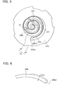
- FIG 5 shows another configuration of the compression mechanism 15 which is different from that shown in FIG 2 .
- FIG 5 is a cross-sectional view along the line II-II in FIG. 1 .
- a ratio h2/d2 (or h1/d1) is preferably greater than or equal to 13 and less than or equal to 19, where h2 (or h1) is the height of the scroll portion 26b (or 24b) from the plate portion 26a (or 24a), and d2 (or d1) is the thickness of the scroll portion 26b (or 24b).
- an end portion 24b2 of the outmost wall of the first scroll portion 24b is supported by another portion 24d of the fixed scroll 24. Therefore, even if the fixed scroll 24 is a semi-molten die cast molding and has the small thickness d1, the material workability of the first scroll portion 24b would not worsen easily.
- an end portion 26b2 of the outmost wall of the second scroll portion 26b is, unlike the end portion 24b2 of the fixed scroll 24, not supported. Therefore, when the second scroll portion 26b, especially the end portion 26b2, is fabricated, its material workability can worsen easily due to the bending thereof.
- a semi-molten die cast molding has 2.4 to 3.6 times more strength than a FC250 casting does (based on "600MPa/250MPa to 900MPa/250MPa")
- the semi-molten die cast molding has no more than 1.6 to 1.7 times more stiffness than a FC250 casting does (based on "175GPa/110GPa to 190GPa/110GPa”). Therefore, when the thickness d2 (or d1) is determined based on the strength so as to prevent rupture, the scroll portion 26b (or 24b) can be bent easily.
- the movable scroll 26 is the semi-molten die cast molding
- a portion near the end portion 26b2 of the outmost wall of the second scroll portion 26b needs to be thicker than the other portions before fabrication.
- the second scroll portion 26b can be fabricated with great precision.
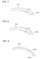
- FIG. 6 , FIG. 7 and FIG 8 shows a configuration of a pre-fabricated second scroll portion 26b.
- FIG. 6 , FIG 7 and FIG. 8 shows only a portion in the proximity of the end portion 26b2 of the outmost wall of the second scroll portion 26b of the movable scroll 26.
- the portion in the proximity of the end portion 26b2 gets thicker on the outer surface than the other portions of the second scroll portion 26b (See thickness d12).
- the portion in the proximity of the end portion 26b2 is fabricated as follows.
- a finishing process is performed to the inner surface of the second scroll portion 26b.
- the second scroll portion 26b does not bent easily, because the portion in the proximity of the end portion 26b2 gets thicker on the outer surface. Therefore, the finishing process can be performed easily.
- the thick portion is trimmed to finish the process for the portion in the proximity of the end portion 26b2.
- the dashed line indicates the shape of the second scroll portion 26b after trimming.
- the portion in the proximity of the end portion 26b2 gets thicker on the inner surface than the other portions of the second scroll portion 26b (See thickness d13).
- the portion in the proximity of the end portion 26b2 is fabricated as follows.
- a finishing process is performed to the outer surface of the second scroll portion 26b.
- the second scroll portion 26b does not bent easily, because the portion near the end portion 26b2 gets thicker on the inner surface. Therefore, the finishing process can be done easily.
- the thick portion is trimmed to finish the process for the portion near the end portion 26b2.
- the dashed line indicates the shape of the second scroll portion 26b after trimming.
- the portion in the proximity of the end portion 26b2 gets thicker on both the outer and inner surfaces than the other portions of the second scroll portion 26b (See thickness d14).
- the portion in the proximity of the end portion 26b2 is fabricated as follows.
- a roughening process and a finishing process are performed to the outer or inner surface of the second scroll portion 26b in this order.
- the second scroll portion 26b does not bent easily due to these processes, because the portion in the proximity of the end portion 26b2 gets thicker on the outer surface. Therefore, the inner surface can be processed easily.
- the thick portion on the outside is trimmed to finish the process.
- the similar process can be performed when the roughening process and the finishing process are performed to the outer surface.
- the dashed line indicates the shape of the second scroll portion 26b after trimming.
- the end portion 26b2 may be formed longer than the above end portions. More specifically, the movable scroll 26 may include further an extended portion 26b4. The extended portion 26b4 extends from the end portion 26b2 of the outmost wall of the second scroll portion 26b, and does not engage with the first scroll portion 24b of the fixed scroll 24.
- the end portion 26b2 of the outmost wall of the second scroll portion 26b has a high strength and high stiffness due to the extended portion 26b4. Therefore, the second scroll portion 26b can be free from deformation during fabrication.
- the extended portion 26b4 may be left unprocessed, or may be cut out. However, when the extended portion 26b4 is left unprocessed, the following problem can occur.
- the first plate portion 24a of the fixed scroll 24 has a through hole 41b through which refrigerant is drawn (hereinafter, the through hole is called "drawing hole"). Therefore, when the extended portion 26b4 covers the drawing hole 41b during the operation of the compression mechanism 15, a loss of the suction pressure will occur, which decreases the compression efficiency.
- the extended portion 26b4 is designed to be placed not to cover the drawing hole 41b during the operation of the compression mechanism 15. As shown in FIG. 10 and FIG 11 , when a side surface of the extended portion 26b4 has a shape of an arc with a radius of r, the extended portion 26b4 is designed as follows.
- a distance d3 between the extended portion 26b4 and the drawing hole 41b needs to be greater than or equal to the radius r (See FIG 10 ).
- the arc-shaped side surface of the extended portion 26b4 is placed away from a sealing point SP by a distance d4 which is greater than or equal to the radius r (See FIG 11 ), where the sealing point SP is an extreme point at which the fixed scroll 24 is in contact with the second scroll portion 26b of the movable scroll 26.
- FIG. 12 is a graph showing the relationship between the ratio of ⁇ S to d2 ( ⁇ S/d2) and the ratio of L2 to d2 (L2/d2), where ⁇ S is the amount of bending of the second scroll portion 26b at the sealing point SP, d2 is the thickness of the second scroll portion 26b, and L2 is the length of the extended portion 26b4.
- the ratio ⁇ S/d2 is preferably less than or equal to 10. This allows a gap to be made between the first scroll portion 24b of the fixed scroll 24 and the second scroll portion 26b of the movable scroll 26, so as not to decrease the compression efficiency. The gap can reduce the interference between the first scroll portion 24b and the second scroll portion 26b, whereby decreases the noise and the chance of rupture.
- the ratio L2/d2 is preferably greater than or equal to 0.3. This case is especially preferable when the above ratio h2/d2 is 13, which is the lower limit of the preferable range of 13 to 19 (See FIG. 12 ). On the other hand, the ratio L2/d2 is preferably greater than or equal to 2.6 when the ratio h2/d2 is 19, which is the upper limit of the preferable range (See FIG 12 ).
- the height of the extended portion 26b4 may be shorter than the height h2 of the second scroll portion 26b.
- the third embodiment describes a relief hole cut in the fixed scroll 24, with regard to the compression mechanism 15 which has the fixed scroll 24 of the grey iron casting (FC250) and the movable scroll 26 of the semi-molten die cast molding.
- a relief hole 242 is formed in the fixed scroll 24. More specifically, the relief hole 242 is formed in the first plate portion 24a, and is open between the involuted walls of the first scroll portion 24b.
- the relief hole 242 connects the compression space 40 to a discharge space 45 (See FIG 1 ) which will be described later in "Embodiment of scroll compressor".
- the discharge space 45 is located on the opposite side of the movable scroll 26 across the first plate portion 24a of the fixed scroll 24 (See FIG. 1 ).
- both the fixed scroll 24 and the movable scroll 26 have been formed of the grey iron casting (FC250), where the thickness d1 of the first scroll portion 24b is substantially equal to the thickness d2 of the second scroll portion 26b.
- the thickness d1 and d2 need to be sufficiently large to improve strength and stiffness of the scroll portions 24b and 26b.
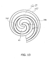
- the diameter of the relief hole 242 conventionally needs to be smaller than or equal to the thickness d2 of the second scroll portion 26b so as not to connect the compression spaces 40 on two sides of the second scroll portion 26b to each other via the relief hole 242.
- the thickness d2 has been large
- the diameter of the relief hole 242 has also been large. Therefore, refrigerant passes through the relief hole 242 easily.
- the thickness d2 of the second scroll portion 26b is small, and the cross-sectional area of the relief hole 241 is equal to that of the conventional relief hole 242 (See FIG. 13 ), the two spaces separated by the second scroll portion 26b in the compression spaces 40 in the compression mechanism 15 will connect to each other, which decreases the compression efficiency.
- FIG 16 is a schematic view of the relief hole 241 applicable in the compression mechanism 15 described in the first and second embodiments.
- FIG 16 is a longitudinal cross-sectional view of the compression mechanism 15 along the arrow 91 shown in FIG 1 .
- the diameter r1 of the opening on the side of the compression space 40 is less than or equal to the thickness d2 of the second scroll portion 26b of the movable scroll 26 (See FIG 16 ).
- the cross-sectional area S2 of the opening on the side of the discharge space 45 is larger than the cross-sectional area S1 of the opening on the side of the compression spaces 40 (See FIG. 16 ).
- the relief hole 241 shown in FIG. 16 is a combination of two holes of different cross-sectional areas. However, the relief hole 241 may be one of the relief holes 241 shown in FIG 17 to 21 .
- FIG 17 is a longitudinal cross-sectional view of the compression mechanism 15 along the arrow 91 shown in FIG 1 .
- the cross-sectional area of the relief hole 241 grows gradually from the compression space 40 to the discharge space 45.
- the relief hole 241 shown in FIG 17 has similar effects as the relief hole 241 shown in FIG 16 .
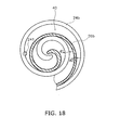
- FIG 18 is a cross-sectional view of the compression mechanism 15 along the line II-II in FIG 1 .
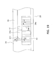
- FIG 19 is a longitudinal cross-sectional view of the compression mechanism 15 shown in FIG. 18 along the arrow 91.
- the relief holes 241 have substantially the same size as the conventional relief hole 242 (See FIG. 13 ).
- the first scroll portion 24b of the fixed scroll 24 covers a portion of the relief hole 241 (See FIG. 18 ).
- the relief hole 241 is covered partly by the first scroll portion 24b of the fixed scroll 24.
- the relief hole 241 shown in FIG. 19 has similar effects as the relief hole 241 shown in FIG 16 .
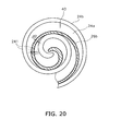
- a plurality of relief holes 241 are formed in the first plate portion 24a.
- Each of the relief holes 241 has a diameter r1 smaller than the thickness d2 of the second scroll portion 26b.
- the first plate portion 24a may have the relief holes which have the shape of ellipsis.
- a discharge hole 41 in the present embodiment is drawn in solid lines, and a conventional discharge hole 41a is drawn in dashed lines.
- the cross-sectional area of the discharge hole 41 is smaller than that of the conventional discharge hole 41a. This is a design modification which is resulted from the small thickness d2 of the second scroll portion 26b.
- the cross-sectional area of the discharge hole 41 decreases, the amount of refrigerant discharged through the discharge hole 41 decreases.
- the plurality of relief holes 241 formed in the first plate portion 24a can be used as auxiliary discharge holes. Therefore, a decrease of discharged refrigerant can be prevented.
- both the refrigerant discharged from the relief holes 241 and that from the discharge hole 41 flow into the same space.
- both the refrigerant discharged from the relief holes 241 and that from the discharge hole 41 are guided into the discharge space 45 (See FIG.1 and FIG. 19 ). Therefore, the refrigerant discharged from the relief holes 241 can also be used as the refrigerant compressed by the compression mechanism 15.
- the scroll compressor 1 includes the casing 11, the compression mechanism 15, an Oldham's ring 2, a fixed member 12, a motor 16, a crankshaft 17, a suction tube 19, a discharge tube 20, and a bearing 60.
- the casing 11 is a cylindrical body elongated along the arrow 91.
- the Oldham's ring 2, the fixed member 12, the motor 16, the crankshaft 17, and the bearing 60 are disposed inside the casing 11.
- the motor 16 includes a stator 51 and a rotor 52.
- the stator 51 is an annular stator secured to the inner wall 11a of the casing 11.
- the rotor 52 is accommodated inside the stator 51.
- the rotor 52 faces to the stator 51 across an air gap.
- the crankshaft 17 is elongated along the arrow 91, and includes a main shaft portion 17a and an eccentric shaft portion 17b.
- the main shaft portion 17a rotates about a rotational axis 90, and is linked to the rotor 52.
- the eccentric shaft portion 17b is disposed at a position not centered at the rotational axis 90, and is linked to the upper side of the main shaft portion 17a.
- the end of the lower side of the crankshaft 17 is supported slidably by the bearing 60.
- the fixed member 12 is a housing shown in FIG. 1 , and is secured hermetically to the inner wall 11 a of the casing 11.
- the fixed member 12 is secured to the inner wall 11 a through press-fitting, welding, and so forth.
- the fixed member 12 may be secured to the inner wall 11a through sealing.
- the fixed member 12 is secured hermetically to the inner wall 11a. That is, the fixed member 12 separates air-tightly the interior space of the casing 11 into a lower space 28 on the lower side of the fixed member 12 and an upper space 29 on the upper side of the fixed member 12. Therefore, the fixed member 12 can resist the pressure difference between the lower space 28 and the upper space 29.
- the pressure in the upper space 28 is higher than that in the upper space 29.
- the fixed member 12 includes a concaved portion 31 which is opened toward the upper side and is cut around the rotational axis 90.
- the eccentric shaft portion 17b of the crankshaft 17 fits in the concaved portion 31.
- the fixed member 12 also includes a bearing 32 and a through hole 33.
- the main shaft portion 17a of the crankshaft 17 passes through the through hole 33, and is supported by the bearing 32.
- the fixed scroll 24 has a concave surface 42 on its upper side.
- the discharge space 45 is defined by the concaved surface 42 and a lid 44.
- the lid 44 separates two spaces of different pressures. One of the two spaces is the discharge space 45, while the other is the upper space 29.
- the movable scroll 26 includes further a bearing 26c.
- the bearing 26c is linked to the lower side of the second plate portion 26a.
- the bearing 26c supports slidably the eccentric shaft portion 17b of the crankshaft 17.
- the refrigerant flow inside the scroll compressor 1 will now be described with reference to FIG 1 .
- the arrows in FIG.1 indicate the refrigerant flow.
- Refrigerant is drawn via the suction tube 19 to be guided into the compression space 40 in the compression mechanism 15.
- the refrigerant compressed in the compression space 40 is discharged into the discharge space 45 via the discharge hole 41 formed in the proximity of the center of the fixed scroll 24. Therefore; the pressure in the discharge space 45 is high.
- the pressure in the upper space 29 separated from the discharge space 45 by the lid 44 stays low.
- the refrigerant in the discharge space 45 flows into the lower space 28 below the fixed member 12, via a through hole 46 formed in the fixed scroll 24 and a through hole 48 formed in the fixed member 12 in this order.
- the refrigerant is guided into a gap 55 by a guide 58.
- the gap 55 is formed between a portion of a side of the stator 51 and the casing 11.
- the refrigerant flows into the lower side of the motor 16 via the gap 55, and flows into the discharge tube 20 via an air gap in the motor 16 or a gap 56.
- the gap 56 is formed between a portion of a side of the stator 51 and the casing 11.
Landscapes
- Engineering & Computer Science (AREA)
- Mechanical Engineering (AREA)
- General Engineering & Computer Science (AREA)
- Chemical & Material Sciences (AREA)
- Materials Engineering (AREA)
- Metallurgy (AREA)
- Organic Chemistry (AREA)
- Rotary Pumps (AREA)
- Applications Or Details Of Rotary Compressors (AREA)
Abstract
Description
- The present invention relates to a compression mechanism and a scroll compressor including the compression mechanism. Particularly, the present invention relates to materials used in the compression mechanism.
- A scroll compressor includes a compression mechanism to compress refrigerant.
The compression mechanism includes a fixed scroll and a movable scroll. Each of the two scrolls has a scroll portion which extends in an involute shape. The two scroll portions engage with each other. - Conventionally, the fixed scroll has been formed of the same material as the movable scroll. Some examples of the materials are a grey iron casting, a cast iron molding fabricated through semi-molten die casting, and so forth.
- The following document (Patent Document 1) discloses the related art to the present invention.
- <
Patent Document 1> Japanese Laid-open Patent Application No.2005-36693 - Unfortunately, when the fixed scroll is formed of the same material as the movable scroll, the following two problems can be raised.
- First, even if the compression mechanism is formed to have high strength and high stiffness, seizing will occur between the fixed scroll and the movable scroll. The seizing can halt the operation of the compression mechanism. This problem will become significant when the scrolls are cast iron moldings fabricated through semi-molten die casting.
- Second, even if the scrolls are formed to have little chance of seizing, the compression mechanism will have low strength and low stiffness. In order to downsize the compression mechanism and maintain the intake capacity thereof simultaneously, the scrolls need to have their involute scroll portions thinner and longer in height. However, low strength and low stiffness of the compression mechanism can cause deformation or rupture of the involute scroll portions during operation. This problem will become significant when the scrolls are grey iron castings.
- The present invention solves the above problems. The present invention has an object to increase strength and stiffness of a compression mechanism and to prevent seizing thereof simultaneously.
- A compression mechanism according to a first aspect of the present invention is used in a scroll compressor, and includes a fixed scroll and a movable scroll. One of the two scrolls is a cast iron molding fabricated through semi-molten die casting, and the other is a grey iron casting.
- A compression mechanism according to a second aspect of the present invention is the compression mechanism according to the first aspect of the present invention, wherein the sum of a graphite area ratio on the surface of the cast iron molding and a graphite area ratio on the surface of the grey iron casting is greater than or equal to 10% and less than or equal to 20%.
- A compression mechanism according to a third aspect of the present invention is the compression mechanism according to the second aspect of the present invention, wherein the graphite area ratio on the surface of the cast iron molding is greater than or equal to 2% and less than or equal to 6%.
- A compression mechanism according to a fourth aspect of the present invention is the compression mechanism according to any one of the first to third aspects of the present invention, wherein a tensile strength of the grey iron casting is greater than or equal to 250N/mm2 and less than 300N/mm2.
- A compression mechanism according to a fifth aspect of the present invention is the compression mechanism according to any one of the first to forth aspects of the present invention, wherein the fixed scroll is the grey iron casting, and the movable scroll is the cast iron molding.
- A compression mechanism according to a sixth aspect of the present invention is the compression mechanism according to the fifth aspect of the present invention, wherein the movable scroll is placed and pushed against the fixed scroll.
- A compression mechanism according to a seventh aspect of the present invention is the compression mechanism according to the fifth or sixth aspect of the present invention, wherein the fixed scroll has a first scroll portion and a first plate portion, and the movable scroll has a second scroll portion and a second plate portion. The first and second scroll portions extend in involute shapes. The first scroll portion engages with the second scroll portion. The first and second plate portions hold the first and second scroll portions respectively. The first plate portion has a through hole which connects a first space and a second space. The first space has an involute shape defined by the first scroll portion. The second space is located on the opposite side of the movable scroll. The second scroll portion is arranged to cover an opening of the through hole. The opening is located on the side of the first space.
- A compression mechanism according to an eighth aspect of the present invention is the compression mechanism according to the seventh aspect of the present invention, wherein the first scroll portion covers a portion of the opening of the through hole, as viewed from the side of the movable scroll.
- A compression mechanism according to a ninth aspect of the present invention is the compression mechanism according to any one of the fifth to eighth aspects of the present invention, wherein the fixed scroll has a first scroll portion, and the movable scroll has a second scroll portion. The first and second scroll portions extend in involute shapes. The first scroll portion engages with the second scroll portion. The movable scroll has an extended portion which extends from the end of the outmost wall of the second scroll portion. The extended portion does not engage with the first scroll portion.
- A compression mechanism according to a tenth aspect of the present invention is the compression mechanism according to any one of the first to ninth aspects of the present invention, wherein the fixed scroll has a first scroll portion, and the movable scroll has a second scroll portion. The first and second scroll portions extend in involute shapes. The first scroll portion engages with the second scroll portion. A thickness ratio of a first thickness to a second thickness is equal to a value calculated based on a Young's modulus ratio of the Young's modulus of the cast iron molding to the Young's modulus of the grey iron casting. In this case, the first thickness is the thickness of the first or second scroll portion of the cast iron molding, and the second thickness is the thickness of the first or second scroll portion of the grey iron casting.
- A compression mechanism according to an eleventh aspect of the present invention is the compression mechanism according to the tenth aspect of the present invention, wherein the thickness ratio is less than or equal to the reciprocal of the Young's modulus ratio.
- A compression mechanism according to a twelfth aspect of the present invention is the compression mechanism according to the tenth or eleventh aspect of the present invention, wherein the Young's modulus of the cast iron molding is 175GPa or more and 190GPa or less.
- A scroll compressor according to a thirteenth aspect of the present invention includes the compression mechanism according to any one of the first to twelfth aspects of the present invention.
- A scroll compressor according to a fourteenth aspect of the present invention is the scroll compressor according to the thirteenth aspect of the present invention, wherein the scroll compressor compresses refrigerant composed mostly of carbon dioxide
- The compression mechanism according to the first aspect has a fixed scroll and a movable scroll. One of the two scrolls is a cast iron molding fabricated through semi-molten die casting, while the other is a grey iron casting. Therefore, in this compression mechanism, seizing does not occur frequently between the fixed scroll and the movable scroll, unlike in a compression mechanism which includes a fixed scroll and a movable scroll, both of which are cast iron moldings fabricated through semi-molten die casting.
- Additionally, when each of the fixed scroll and the movable scroll has a scroll portion which extends in an involute shape and engages with the other scroll portion, the compression mechanism of the present invention can have thinner scroll portions, unlike a compression mechanism which includes a fixed scroll and a movable scroll, both of which are grey iron castings. This is because a cast iron molding fabricated through semi-molten die casting has higher strength and higher stiffness than a grey iron casting. Therefore, this compression mechanism can be downsized and maintain its intake capacity simultaneously. This compression mechanism can also keep its size unchanged and achieve higher intake capacity simultaneously.
- Additionally, this compression mechanism can prevent deformation thereof caused by compression pressure. This is because a cast iron molding fabricated through semi-molten die casting has higher stiffness than a grey iron casting. Therefore, compressed refrigerant hardly leaks out of this compression mechanism, which prevents a decrease of the compression efficiency.
- The compression mechanism according to the second aspect has a large sum of the graphite area ratios, which can easily prevent seizing between the fixed scroll and the movable scroll.
- The compression mechanism according to the third aspect can secure the graphite area ratio on the surface of the cast iron molding, which is sufficient to prevent seizing. This compression mechanism can easily prevent seizing between the fixed scroll and the movable scroll.
- The compression mechanism according to the fourth aspect can have the strength and the stiffness sufficient to prevent deformation or rupture of this compression mechanism.
- When each of the fixed scroll and the movable scroll has a scroll portion which extends in an involute shape and engages with the other scroll portion, the compression mechanism according to the fifth aspect can have thinner scroll portions, unlike a compression mechanism which includes a fixed scroll and a movable scroll, both of which are grey iron castings. This is because a cast iron molding fabricated through semi-molten die casting has higher strength and higher stiffness than a grey iron casting. Therefore, this compression mechanism can be downsized and maintain its intake capacity simultaneously. This compression mechanism can also keep its size unchanged and achieve higher intake capacity simultaneously.
- Additionally, the movable scroll can be lightweight, which reduces torque required to operate the movable scroll.
- Additionally, the cast iron molding fabricated through semi-molten die casting can reduce the cost of this compression mechanism.
- The compression mechanism according to the sixth aspect can prevent a gap between the scroll portion of the fixed scroll and that of the movable scroll, whereby prevents the decrease of the compression efficiency.
- Additionally, the movable scroll is unlikely to deform when pushed against the fixed scroll. This is because the movable scroll is the cast iron molding fabricated through semi-molten die casting which has high strength and high stiffness.
- The compression mechanism according to the seventh aspect can prevent the decrease of the compression efficiency. This is because the through hole does not connect the first spaces on two sides of the scroll portion of the movable scroll, when the scroll portion of the movable scroll passes by an opening of the through hole. More specifically, in this case, the first spaces defined by the scroll portion do not connect to each other via the through hole.
- The compression mechanism according to the eighth aspect has an opening of the through hole on the side of the second space, and this opening can be bigger than an opening on the side of the first space. Therefore, compressed refrigerant can pass through the through hole more efficiently.
- The compression mechanism according to the ninth aspect has the movable scroll with the extended portion, which increases strength and stiffness of the end of the outmost wall of the movable scroll. Therefore, the extended portion prevents deformation of the outmost wall of the movable scroll during fabrication.
- The compression mechanism according to the tenth aspect can have substantially equal amounts of bending between the two scroll portions, wherein one of the scroll portions is a cast iron molding fabricated through semi-molten die casting, while the other is a grey iron casting. This is because the thickness ratio of the scroll portions is calculated based on the Young's modulus ratio of the scroll portions. The compression mechanism can prevent the decrease of the compression efficiency due to the bending of the scroll portions.
- The compression mechanism according to the eleventh aspect can be downsized.
This is because a scroll portion of the cast iron molding can be made thinner. - The compression mechanism according to the twelfth aspect can prevent the decrease of the compression efficiency due to the bending of the cast iron molding.
- The scroll compressor according to the thirteenth aspect can prevent seizing between the fixed scroll and the movable scroll of the compression mechanism. Therefore, the scroll compressor is less prone to breakdown.
- The scroll compressor according to the fourteenth aspect can improve the compression efficiency, even when carbon dioxide is used as refrigerant.
-
-
FIG. 1 is a schematic cross-sectional view of a scroll compressor according to an embodiment of the present invention. -
FIG. 2 is a cross-sectional view of acompression mechanism 15 along the line II-II inFIG. 1 . -
FIG. 3 is a table showing surface pressure for seizing to occur, graphite area ratio, and hardness. -
FIG. 4 is a graph showing the relationship between graphite area ratio and surface pressure for seizing to occur. -
FIG. 5 is a cross-sectional view of acompression mechanism 15 whose configuration is different from that ofFIG. 2 . -
FIG. 6 is a schematic view of a scroll portion, the outmost wall of which has a thick end. -
FIG. 7 is a schematic view of a scroll portion, the outmost wall of which has a thick end. -
FIG. 8 is a schematic view of a scroll portion, the outmost wall of which has a thick end. -
FIG. 9 is a schematic view of a movable scroll with an extended portion. -
FIG. 10 is a schematic view of a movable scroll with an extended portion. -
FIG. 11 is a schematic view of a movable scroll with an extended portion. -
FIG. 12 is a graph showing the relationship between the ratio of bending (ΔS) to thickness (d2) and the ratio of length (L2) to thickness (d2). -
FIG. 13 is a schematic view of a conventional compression mechanism with a relief hole. -
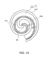
FIG. 14 is a schematic view of a conventional compression mechanism with a thin scroll portion. -
FIG. 15 is a schematic view of a conventional compression mechanism with a narrower relief hole. -
FIG. 16 is a schematic view of arelief hole 241 used in acompression mechanism 15. -
FIG. 17 is a schematic view of arelief hole 241 used in acompression mechanism 15. -
FIG. 18 is a schematic view of arelief hole 241 used in acompression mechanism 15. -
FIG. 19 is a cross-sectional view of a relief hole along thearrow 91 inFIG. 1 . -
FIG. 20 is a schematic view of a compression mechanism with a plurality ofrelief holes 241 formed in aplate portion 24a. -
FIG. 21 is a schematic view of a compression mechanism with a plurality ofrelief holes 241 formed in aplate portion 24a. -
- 1
- Scroll compressor
- 15
- Compression mechanism
- 24
- Fixed scroll
- 26
- Movable scroll
- 24a, 26a
- Plate portion
- 24b, 26b
- Scroll portion
- 26b2
- End portion
- 26b4
- Extended portion
- 40,45
- Space
- 241
- Relief hole (Through hole)
- d1, d2
- Thickness
- d1/d2, d2/d1
- Ratio
-
FIG 1 shows a schematic view of ascroll compressor 1 according to an embodiment of the present invention. Hereinafter, "the upper side" is defined as a side pointed by anarrow 91 shown inFIG 1 , and "the lower side" is defined as the opposite side to the upper side. - The
scroll compressor 1 includes acasing 11 and acompression mechanism 15.
Thecasing 11 is a cylindrical body elongated along thearrow 91. Thecompression mechanism 15 is disposed inside thecasing 11. -
FIG 2 shows a cross-sectional view of thecompression mechanism 15 along the line II-II shown inFIG 1 . Thecompression mechanism 15 includes a fixedscroll 24 and a movable scroll 26 (SeeFIG 1 andFIG 2 ). Thecompression mechanism 15 compresses refrigerant. An example of the refrigerant is composed mostly of carbon dioxide. - The fixed
scroll 24 includes afirst plate portion 24a and afirst scroll portion 24b.
Thefirst plate portion 24a is secured to an inner wall 11 a of thecasing 11. Thefirst scroll portion 24b is attached to the lower side of thefirst plate portion 24a (SeeFIG 1 ). Thefirst scroll portion 24b extends in an involute shape, and forms aspiral channel 24c between its involuted walls (SeeFIG 2 ). Thefirst plate portion 24a is a fixing member which holds thefirst scroll portion 24b. - The
movable scroll 26 includes a second plate portion 26a and asecond scroll portion 26b. Thesecond scroll portion 26b is attached to the upper side of the second plate portion 26a (SeeFIG 1 ). Thesecond scroll portion 26b extends in an involute shape (SeeFIG 2 ). The second plate portion 26a is another fixing member which holds thesecond scroll portion 26b. - The
second scroll portion 26b fits in thespiral channel 24c of the fixed scroll 24 (SeeFIG 2 ). Thecompression mechanism 15 has acompression space 40 between thefirst scroll portion 24b and thesecond scroll portion 26b. Thecompression space 40 is confined by thefirst plate portion 24a and the second plate portion 26a, and is used as a compression chamber which compresses refrigerant (SeeFIG. 1 ). - In the
compression mechanism 15, the following first to third embodiments of the present invention describe respectively materials used for the fixedscroll 24 and themovable scroll 26, configurations of thefirst scroll portion 24b and thesecond scroll portion 26b, and a relief hole in the fixedscroll 24. - In the
compression mechanism 15 of the first embodiment, a material used for the fixedscroll 24 is different from that for themovable scroll 26. - More specifically, one of the fixed
scroll 24 and themovable scroll 26 is a cast iron molding fabricated through semi-molten die casting (hereinafter, this molding is called "semi-molten die cast molding"). The semi-molten die cast molding has a tensile strength of greater than or equal to 600N/mm2 and less than or equal to 900N/mm2. - The other one of the fixed
scroll 24 and themovable scroll 26 is a grey iron casting.
The grey iron casting has a tensile strength of greater than or equal to 250N/mm2 and less than 300N/mm2. The tensile strength can ensure sufficient strength and stiffness of the grey iron casting to prevent deformation or rupture thereof. According to JIS (Japanese Industrial Standards), a grey iron casting that has a tensile strength of greater than or equal to 250N/mm2 and less than 300N/mm2 is a FC250. -
FIG 3 is a table showing surface pressure for seizing to occur (MPa), graphite area ratio (%), and hardness (HRB) of thecompression mechanism 15. The surface pressure for seizing to occur represents the pressure which causes seizing to occur during a seizing test. The seizing test is implemented by sliding a pin-shaped molding (hereinafter, this molding is called "pin") on the surface of a disk-shaped molding (hereinafter, this molding is called "disk") based on a predetermined method. The predetermined method is as follows: soak a disk and a pin in a mixture of refrigerant R410A and ethereal oil (at 100 degrees centigrade); slide the pin at an average speed of 2.0m/s; change a surface pressure between the pin and the disk; observe whether or not seizing occurs between the pin and the disk to measure the surface pressure which causes seizing to occur between the pin and the disk. The graphite area ratio represents an area occupied by graphite per unit area of thecompression mechanism 15. - In
FIG 3 , "slider A" is one of the fixedscroll 24 and themovable scroll 26, while "slider B" is the other. The graphite area ratio (%) and the hardness (HRB) of each of the slider A and B are shown respectively inFIG 3 . Hereinafter, a sum of the graphite area ratio of each of the slider A and B is called "total graphite area ratio" which is shown in the table ofFIG 3 (See the column "slider A + slider B"). -
FIG 3 shows a seizing test result between a pin-shaped semi-molten die cast molding and a disk-shaped grey iron casting (See the row "semi-molten die cast molding/FC250"). For comparison,FIG. 3 also shows seizing test results for pins and disks made of the same materials. More specifically,FIG 3 shows a seizing test result between a pin-shaped grey iron casting (FC250) and a disk-shaped grey iron casting (FC250) (See the row "FC250s"), and a seizing test result between a pin-shaped semi-molten die cast molding and a disk-shaped semi-molten die cast molding (See the row "semi-molten die cast moldings"). - As shown in
FIG 3 , the "semi-molten die cast molding/FC250" test result is as follows: the surface pressure for seizing to occur is 152MPa; the total graphite area ratio is 10% to 20%; the graphite area ratio of the slider A is 2% to 6%; the graphite area ratio of the slider B is 8% to 14%; the hardness of the slider A is HRB90 to HRB100; and the hardness of the slider B is HRB90 to HRB100. In this case, the slider A is the semi-molten die cast molding, and the slider B is the grey iron casting (FC250). - As shown in
FIG 3 , the "FC250s" test result is as follows: the surface pressure for seizing to occur is 169MPa; the total graphite area ratio is 28%; the graphite area ratios of the slider A and slider B are both 14%; the hardness of the slider A and slider B are both HRB93. - As shown in
FIG. 3 , the "semi-molten die cast moldings" test result is as follows: the surface pressure for seizing to occur is 140MPa; the total graphite area ratio is 8%; the graphite area ratios of the slider A and slider B are both 4.0%; the hardness of the slider A and slider B are both HRB98. -
FIG 3 shows that the surface pressure for seizing to occur in the "semi-molten die cast molding/FC250" test is higher than that in the "semi-molten die cast moldings" test. The reason is presented as follows. -
FIG 4 is a graph showing the relationship between the total graphite area ratio and the surface pressure for seizing to occur.FIG 4 suggests that a higher total graphite area ratio results in a higher surface pressure for seizing to occur. Accordingly, because the total graphite area ratio in the "semi-molten die cast molding/FC250" test is higher than that in the "semi-molten die cast moldings" test, their surface pressures for seizing to occur also show a similar trend. - The "semi-molten die cast molding/FC250" test shows that the graphite area ratio of the grey iron casting (FC250) is 8% to 14% which is notably higher than that of the semi-molten die cast molding, 2% to 6%. The remarkable difference of the graphite area ratio between the pin and the disk will be one of the factors that result in the increase of the surface pressure for seizing. The semi-molten die cast molding needs to have a graphite area ratio of at least 2% in order to prevent seizing.
- Consequently, the
compression mechanism 15 according to the first embodiment can easily prevent seizing between the fixedscroll 24 and themovable scroll 26, compared to a compression mechanism which includes a fixed scroll and a movable scroll, both of which are semi-molten die cast moldings. - Additionally, the
compression mechanism 15 has a higher hardness, higher strength, and higher stiffness than a compression mechanism which includes a fixed scroll and a movable scroll, both of which are grey iron castings (FC250). Therefore, either the fixedscroll 24 or themovable scroll 26, whichever is the semi-molten die cast molding, can have the smaller thickness d2 (or d1) of thescroll portion 26b (or 24b) (SeeFIG.2 ), and have thescroll portion 26b (or 24b) longer in height. This scroll results in downsizing thecompression mechanism 15 without decreasing the compression efficiency. This scroll also results in increasing the intake capacity without changing the size of thecompression mechanism 15. - In the
compression mechanism 15, the graphite area ratio of the semi-molten die cast molding is preferably 4% to 6%. This is because the material workability of the semi-molten die cast molding will improve, due to the hardness thereof which can get near to HRB90 (more specifically, HRB90 to HRB95). - In addition, in the
compression mechanism 15, the fixedscroll 24 is preferably the grey iron casting (FC250) and themovable scroll 26 is preferably the semi-molten die cast molding. In this case, because the semi-molten die cast molding has a higher strength and higher stiffness, themovable scroll 26 of the semi-molten die cast molding can have the thinnersecond scroll portion 26b and the thinner second plate portion 26a. - Consequently, the
compression mechanism 15 can be downsized without changing the intake capacity. Alternatively, thecompression mechanism 15 can also increase the intake capacity without changing its size. In addition, themovable scroll 26 can be lightweight, which reduces torque required to operate themovable scroll 26. The semi-molten die cast molding can reduce the cost of thecompression mechanism 15. - The
movable scroll 26 is placed and pushed against the fixedscroll 24. This prevents a gap between the fixedscroll 24 and thesecond scroll portion 26b of themovable scroll 26, whereby prevents a decrease of the compression efficiency. - In this case, the
movable scroll 26 pushed against the fixedscroll 24 is the semi-molten die cast molding. This is because themovable scroll 26 has a high strength and high stiffness. That is, even if themovable scroll 26 is pushed against the fixedscroll 24, thesecond scroll portion 26b will not deform easily. - The second embodiment describes the configuration of the
compression mechanism 15 described in the first embodiment. Thickness of scroll portions - As described in the first embodiment, when any one of the fixed
scroll 24 and themovable scroll 26 is the semi-molten die cast molding, that scroll 26 (or 24) has a high strength and high stiffness. In this case, the scroll 26 (or 24) becomes less prone to rupture and bending. - In addition, the scroll 26 (or 24) with high strength and high stiffness can have the
scroll portion 26b (or 24b) with a small thickness d2 (or d1). However, while a semi-molten die cast molding has 2.4 to 3.6 times more strength than a FC250 casting does (based on "600MPa/250MPa to 900MPa/250MPa", where "600MPa" and "900MPa" are experimental values of strength for a semi-molten die cast molding), a semi-molten die cast molding has no more than 1.6 to 1.7 times more stiffness than a FC250 casting does (based on "175GPa/110GPa to 190GPa/110GPa", where "175GPa" and "190GPa" are experimental values of stiffness for a semi-molten die cast molding). Therefore, when the thickness d2 (or d1) is determined based on the strength so as to prevent rupture, thescroll portion 26b (or 24b) can be bent easily. - For this reason, a thickness ratio d2/d1 (or d1/d2) is calculated based on a Young's modulus ratio α. In this case, the thickness ratio d2/d1 (or d1/d2) is a ratio of the thickness d2 (or d1) of the
scroll portion 26b (or 24b) of the semi-molten die cast molding to the thickness d1 (or d2) of thescroll portion 24b (or 26b) of the grey iron casting. The Young's modulus ratio α is a ratio of the Young's modulus of the semi-molten die cast molding to the Young's modulus of the grey iron casting. - For example, when the fixed
scroll 24 is a grey iron casting and themovable scroll 26 is a semi-molten die cast molding, the thickness ratio d2/d1 is given a value calculated based on the Young's modulus ratio α, where d1 is the thickness of thefirst scroll portion 24b and d2 is the thickness of thesecond scroll portion 26b. - The Young's modulus ratio α can be about 1.6. The Young's modulus of the semi-molten die cast molding is preferably greater than or equal to 175GPa and less than or equal to 190GPa, so as to prevent a decrease of the compression efficiency caused by bending of the semi-molten die cast molding.
- When the thickness d1 and d2 are determined through the thickness ratio d2/d1 (or d1/d2) calculated based on the Young's modulus ratio α, the amount of bending of the
first scroll portion 24b can be almost equal to that of thesecond scroll portion 26b. Therefore, in thecompression mechanism 15, the decrease of the compression efficiency caused by bending of thescroll portions - In order to achieve a downsized
compression mechanism 15 while maintaining a high intake capacity by decreasing the thickness d2 (or d1) of the scroll portion of the semi-molten die cast molding, the thickness ratio d2/d1 (or d1/d2) needs to be less than or equal to the reciprocal of the Young's modulus ratio α (that is, 1/α). - When the fixed
scroll 24 is a semi-molten die cast molding and themovable scroll 26 is a grey iron casting, the thickness ratio d1/d2 needs to be calculated based on the Young's modulus ratio α, where d1 is the thickness of thefirst scroll portion 24b and d2 is the thickness of thesecond scroll portion 26b. In this case, as described above, the amount of bending of thefirst scroll portion 24b can become almost equal to that of thesecond scroll portion 26b. -
FIG 5 shows another configuration of thecompression mechanism 15 which is different from that shown inFIG 2 .FIG 5 is a cross-sectional view along the line II-II inFIG. 1 . - As described in the first embodiment, when one of the fixed
scroll 24 and themovable scroll 26 is a semi-molten die cast molding, that scroll can have the small thickness d2 (or d1) of thescroll portion 26b (or 24b). Considering the bending of thescroll portion 26b (or 24b) during the operation of thecompression mechanism 15, a ratio h2/d2 (or h1/d1) is preferably greater than or equal to 13 and less than or equal to 19, where h2 (or h1) is the height of thescroll portion 26b (or 24b) from the plate portion 26a (or 24a), and d2 (or d1) is the thickness of thescroll portion 26b (or 24b). - In the fixed
scroll 24, an end portion 24b2 of the outmost wall of thefirst scroll portion 24b is supported by anotherportion 24d of the fixedscroll 24. Therefore, even if the fixedscroll 24 is a semi-molten die cast molding and has the small thickness d1, the material workability of thefirst scroll portion 24b would not worsen easily. - On the other hand, in the
movable scroll 26, an end portion 26b2 of the outmost wall of thesecond scroll portion 26b is, unlike the end portion 24b2 of the fixedscroll 24, not supported. Therefore, when thesecond scroll portion 26b, especially the end portion 26b2, is fabricated, its material workability can worsen easily due to the bending thereof. - In addition, while a semi-molten die cast molding has 2.4 to 3.6 times more strength than a FC250 casting does (based on "600MPa/250MPa to 900MPa/250MPa"), the semi-molten die cast molding has no more than 1.6 to 1.7 times more stiffness than a FC250 casting does (based on "175GPa/110GPa to 190GPa/110GPa"). Therefore, when the thickness d2 (or d1) is determined based on the strength so as to prevent rupture, the
scroll portion 26b (or 24b) can be bent easily. - For this reason, when the
movable scroll 26 is the semi-molten die cast molding, a portion near the end portion 26b2 of the outmost wall of thesecond scroll portion 26b needs to be thicker than the other portions before fabrication. In this case, thesecond scroll portion 26b can be fabricated with great precision. - Each of
FIG. 6 ,FIG. 7 and FIG 8 shows a configuration of a pre-fabricatedsecond scroll portion 26b. Each ofFIG. 6 ,FIG 7 and FIG. 8 shows only a portion in the proximity of the end portion 26b2 of the outmost wall of thesecond scroll portion 26b of themovable scroll 26. - In
FIG 6 , the portion in the proximity of the end portion 26b2 gets thicker on the outer surface than the other portions of thesecond scroll portion 26b (See thickness d12). In this case, the portion in the proximity of the end portion 26b2 is fabricated as follows. - First, a finishing process is performed to the inner surface of the
second scroll portion 26b. In this case, thesecond scroll portion 26b does not bent easily, because the portion in the proximity of the end portion 26b2 gets thicker on the outer surface. Therefore, the finishing process can be performed easily. - After that, the thick portion is trimmed to finish the process for the portion in the proximity of the end portion 26b2. In
FIG. 6 , the dashed line indicates the shape of thesecond scroll portion 26b after trimming. - In
FIG 7 , the portion in the proximity of the end portion 26b2 gets thicker on the inner surface than the other portions of thesecond scroll portion 26b (See thickness d13). In this case, the portion in the proximity of the end portion 26b2 is fabricated as follows. - First, a finishing process is performed to the outer surface of the
second scroll portion 26b. In this case, thesecond scroll portion 26b does not bent easily, because the portion near the end portion 26b2 gets thicker on the inner surface. Therefore, the finishing process can be done easily. - After that, the thick portion is trimmed to finish the process for the portion near the end portion 26b2. In
FIG 7 , the dashed line indicates the shape of thesecond scroll portion 26b after trimming. - In
FIG. 8 , the portion in the proximity of the end portion 26b2 gets thicker on both the outer and inner surfaces than the other portions of thesecond scroll portion 26b (See thickness d14). In this case, the portion in the proximity of the end portion 26b2 is fabricated as follows. - First, a roughening process and a finishing process are performed to the outer or inner surface of the
second scroll portion 26b in this order. For example, when the rough process and the finishing process are performed to the inner surface, thesecond scroll portion 26b does not bent easily due to these processes, because the portion in the proximity of the end portion 26b2 gets thicker on the outer surface. Therefore, the inner surface can be processed easily. - After that, the thick portion on the outside is trimmed to finish the process. The similar process can be performed when the roughening process and the finishing process are performed to the outer surface. In
FIG. 8 , the dashed line indicates the shape of thesecond scroll portion 26b after trimming. - As shown in
FIG 9 , the end portion 26b2 may be formed longer than the above end portions. More specifically, themovable scroll 26 may include further an extended portion 26b4. The extended portion 26b4 extends from the end portion 26b2 of the outmost wall of thesecond scroll portion 26b, and does not engage with thefirst scroll portion 24b of the fixedscroll 24. - In the
movable scroll 26 shown inFIG 9 , the end portion 26b2 of the outmost wall of thesecond scroll portion 26b has a high strength and high stiffness due to the extended portion 26b4. Therefore, thesecond scroll portion 26b can be free from deformation during fabrication. - After the
second scroll portion 26b is fabricated, the extended portion 26b4 may be left unprocessed, or may be cut out. However, when the extended portion 26b4 is left unprocessed, the following problem can occur. - As shown in
FIG. 10 andFIG 11 , in the proximity of the end portion 26b2 of the outmost wall of thesecond scroll portion 26b, thefirst plate portion 24a of the fixedscroll 24 has a throughhole 41b through which refrigerant is drawn (hereinafter, the through hole is called "drawing hole"). Therefore, when the extended portion 26b4 covers thedrawing hole 41b during the operation of thecompression mechanism 15, a loss of the suction pressure will occur, which decreases the compression efficiency. - For this reason, the extended portion 26b4 is designed to be placed not to cover the
drawing hole 41b during the operation of thecompression mechanism 15. As shown inFIG. 10 andFIG 11 , when a side surface of the extended portion 26b4 has a shape of an arc with a radius of r, the extended portion 26b4 is designed as follows. - When the extended portion 26b4 gets closest to the
drawing hole 41b during the operation of thecompression mechanism 15, a distance d3 between the extended portion 26b4 and thedrawing hole 41b needs to be greater than or equal to the radius r (SeeFIG 10 ). - In addition, the arc-shaped side surface of the extended portion 26b4 is placed away from a sealing point SP by a distance d4 which is greater than or equal to the radius r (See
FIG 11 ), where the sealing point SP is an extreme point at which the fixedscroll 24 is in contact with thesecond scroll portion 26b of themovable scroll 26. -
FIG. 12 is a graph showing the relationship between the ratio of ΔS to d2 (ΔS/d2) and the ratio of L2 to d2 (L2/d2), where ΔS is the amount of bending of thesecond scroll portion 26b at the sealing point SP, d2 is the thickness of thesecond scroll portion 26b, and L2 is the length of the extended portion 26b4. - The ratio ΔS/d2 is preferably less than or equal to 10. This allows a gap to be made between the
first scroll portion 24b of the fixedscroll 24 and thesecond scroll portion 26b of themovable scroll 26, so as not to decrease the compression efficiency. The gap can reduce the interference between thefirst scroll portion 24b and thesecond scroll portion 26b, whereby decreases the noise and the chance of rupture. - Therefore, considering the relationship between the length L2 of the extended portion 26b4 and the thickness d2 of the
second scroll portion 26b, the ratio L2/d2 is preferably greater than or equal to 0.3. This case is especially preferable when the above ratio h2/d2 is 13, which is the lower limit of the preferable range of 13 to 19 (SeeFIG. 12 ). On the other hand, the ratio L2/d2 is preferably greater than or equal to 2.6 when the ratio h2/d2 is 19, which is the upper limit of the preferable range (SeeFIG 12 ). - The height of the extended portion 26b4 may be shorter than the height h2 of the
second scroll portion 26b. - The third embodiment describes a relief hole cut in the fixed
scroll 24, with regard to thecompression mechanism 15 which has the fixedscroll 24 of the grey iron casting (FC250) and themovable scroll 26 of the semi-molten die cast molding. - First of all, a conventional relief hole will be described with reference to
FIG. 13 . Arelief hole 242 is formed in the fixedscroll 24. More specifically, therelief hole 242 is formed in thefirst plate portion 24a, and is open between the involuted walls of thefirst scroll portion 24b. Therelief hole 242 connects thecompression space 40 to a discharge space 45 (SeeFIG 1 ) which will be described later in "Embodiment of scroll compressor".
Thedischarge space 45 is located on the opposite side of themovable scroll 26 across thefirst plate portion 24a of the fixed scroll 24 (SeeFIG. 1 ). - Conventionally, both the fixed
scroll 24 and themovable scroll 26 have been formed of the grey iron casting (FC250), where the thickness d1 of thefirst scroll portion 24b is substantially equal to the thickness d2 of thesecond scroll portion 26b. In this case, the thickness d1 and d2 need to be sufficiently large to improve strength and stiffness of thescroll portions - In addition, the diameter of the
relief hole 242 conventionally needs to be smaller than or equal to the thickness d2 of thesecond scroll portion 26b so as not to connect thecompression spaces 40 on two sides of thesecond scroll portion 26b to each other via therelief hole 242. However, because the thickness d2 has been large, the diameter of therelief hole 242 has also been large. Therefore, refrigerant passes through therelief hole 242 easily. - However, as shown in
FIG 14 , when themovable scroll 26 is a semi-molten die cast molding, the thickness d2 of thesecond scroll portion 26b is small, and the cross-sectional area of therelief hole 241 is equal to that of the conventional relief hole 242 (SeeFIG. 13 ), the two spaces separated by thesecond scroll portion 26b in thecompression spaces 40 in thecompression mechanism 15 will connect to each other, which decreases the compression efficiency. - In addition, as shown in
FIG 15 , when the cross-sectional area of therelief hole 241 is too small, refrigerant will not pass through therelief hole 241 smoothly. -
FIG 16 is a schematic view of therelief hole 241 applicable in thecompression mechanism 15 described in the first and second embodiments.FIG 16 is a longitudinal cross-sectional view of thecompression mechanism 15 along thearrow 91 shown inFIG 1 . - In the
relief hole 241, the diameter r1 of the opening on the side of thecompression space 40 is less than or equal to the thickness d2 of thesecond scroll portion 26b of the movable scroll 26 (SeeFIG 16 ). In therelief hole 241, the cross-sectional area S2 of the opening on the side of thedischarge space 45 is larger than the cross-sectional area S1 of the opening on the side of the compression spaces 40 (SeeFIG. 16 ). - In this case, even if the thickness d2 of the
second scroll portion 26b of themovable scroll 26 is small, the two spaces separated by thesecond scroll portion 26b in thecompression spaces 40 will not connect to each other via therelief hole 241. Therefore, a decrease of the compression efficiency can be prevented. - In addition, because the cross-sectional area S2 of the opening of the
relief hole 241 on the side of thedischarge space 45 is large, refrigerant can flow into thedischarge space 45 via therelief hole 241 smoothly. Therefore, the compressed refrigerant will be discharged efficiently. - The
relief hole 241 shown inFIG. 16 is a combination of two holes of different cross-sectional areas. However, therelief hole 241 may be one of the relief holes 241 shown inFIG 17 to 21 . -
FIG 17 is a longitudinal cross-sectional view of thecompression mechanism 15 along thearrow 91 shown inFIG 1 . InFIG 17 , the cross-sectional area of therelief hole 241 grows gradually from thecompression space 40 to thedischarge space 45. Therelief hole 241 shown inFIG 17 has similar effects as therelief hole 241 shown inFIG 16 . -
FIG 18 is a cross-sectional view of thecompression mechanism 15 along the line II-II inFIG 1 .FIG 19 is a longitudinal cross-sectional view of thecompression mechanism 15 shown inFIG. 18 along thearrow 91. InFIG. 18 andFIG 19 , the relief holes 241 have substantially the same size as the conventional relief hole 242 (SeeFIG. 13 ). However, thefirst scroll portion 24b of the fixedscroll 24 covers a portion of the relief hole 241 (SeeFIG. 18 ). In other words, as viewed from themovable scroll 26, therelief hole 241 is covered partly by thefirst scroll portion 24b of the fixedscroll 24. - In this
relief hole 241, the cross-sectional area S1 of the opening on the side of thecompression spaces 40 is small, and the cross-sectional area S2 of the opening on the side of thedischarge space 45 is large (SeeFIG. 19 ). Therefore, therelief hole 241 shown inFIG. 19 has similar effects as therelief hole 241 shown inFIG 16 . - In
FIG 20 andFIG 21 , a plurality ofrelief holes 241 are formed in thefirst plate portion 24a. Each of the relief holes 241 has a diameter r1 smaller than the thickness d2 of thesecond scroll portion 26b. For example, thefirst plate portion 24a may have the relief holes which have the shape of ellipsis. - In
FIG. 21 , adischarge hole 41 in the present embodiment is drawn in solid lines, and aconventional discharge hole 41a is drawn in dashed lines. The cross-sectional area of thedischarge hole 41 is smaller than that of theconventional discharge hole 41a. This is a design modification which is resulted from the small thickness d2 of thesecond scroll portion 26b. - When the cross-sectional area of the
discharge hole 41 decreases, the amount of refrigerant discharged through thedischarge hole 41 decreases. However, as shown inFIG 21 , the plurality ofrelief holes 241 formed in thefirst plate portion 24a can be used as auxiliary discharge holes. Therefore, a decrease of discharged refrigerant can be prevented. - More specifically, in this case, both the refrigerant discharged from the relief holes 241 and that from the
discharge hole 41 flow into the same space. In the present embodiment, both the refrigerant discharged from the relief holes 241 and that from thedischarge hole 41 are guided into the discharge space 45 (SeeFIG.1 andFIG. 19 ). Therefore, the refrigerant discharged from the relief holes 241 can also be used as the refrigerant compressed by thecompression mechanism 15. Embodiment of the scroll compressor - The configuration of the
scroll compressor 1 will now be described in details with reference toFIG 1 . Thescroll compressor 1 includes thecasing 11, thecompression mechanism 15, an Oldham'sring 2, a fixedmember 12, amotor 16, acrankshaft 17, asuction tube 19, adischarge tube 20, and abearing 60. - The
casing 11 is a cylindrical body elongated along thearrow 91. The Oldham'sring 2, the fixedmember 12, themotor 16, thecrankshaft 17, and thebearing 60 are disposed inside thecasing 11. - The
motor 16 includes astator 51 and arotor 52. Thestator 51 is an annular stator secured to the inner wall 11a of thecasing 11. Therotor 52 is accommodated inside thestator 51. Therotor 52 faces to thestator 51 across an air gap. - The
crankshaft 17 is elongated along thearrow 91, and includes amain shaft portion 17a and aneccentric shaft portion 17b. Themain shaft portion 17a rotates about arotational axis 90, and is linked to therotor 52. Theeccentric shaft portion 17b is disposed at a position not centered at therotational axis 90, and is linked to the upper side of themain shaft portion 17a. The end of the lower side of thecrankshaft 17 is supported slidably by thebearing 60. - The fixed
member 12 is a housing shown inFIG. 1 , and is secured hermetically to the inner wall 11 a of thecasing 11. The fixedmember 12 is secured to the inner wall 11 a through press-fitting, welding, and so forth. The fixedmember 12 may be secured to the inner wall 11a through sealing. - The fixed
member 12 is secured hermetically to the inner wall 11a. That is, the fixedmember 12 separates air-tightly the interior space of thecasing 11 into alower space 28 on the lower side of the fixedmember 12 and anupper space 29 on the upper side of the fixedmember 12. Therefore, the fixedmember 12 can resist the pressure difference between thelower space 28 and theupper space 29. The pressure in theupper space 28 is higher than that in theupper space 29. - The fixed
member 12 includes a concaved portion 31 which is opened toward the upper side and is cut around therotational axis 90. Theeccentric shaft portion 17b of thecrankshaft 17 fits in the concaved portion 31. The fixedmember 12 also includes abearing 32 and a throughhole 33. Themain shaft portion 17a of thecrankshaft 17 passes through the throughhole 33, and is supported by thebearing 32. - The fixed
scroll 24 has a concave surface 42 on its upper side. Thedischarge space 45 is defined by the concaved surface 42 and a lid 44. The lid 44 separates two spaces of different pressures. One of the two spaces is thedischarge space 45, while the other is theupper space 29. - The
movable scroll 26 includes further abearing 26c. Thebearing 26c is linked to the lower side of the second plate portion 26a. Thebearing 26c supports slidably theeccentric shaft portion 17b of thecrankshaft 17. - The refrigerant flow inside the
scroll compressor 1 will now be described with reference toFIG 1 . The arrows inFIG.1 indicate the refrigerant flow. Refrigerant is drawn via thesuction tube 19 to be guided into thecompression space 40 in thecompression mechanism 15. The refrigerant compressed in thecompression space 40 is discharged into thedischarge space 45 via thedischarge hole 41 formed in the proximity of the center of the fixedscroll 24. Therefore; the pressure in thedischarge space 45 is high. On the other hand, the pressure in theupper space 29 separated from thedischarge space 45 by the lid 44 stays low. - The refrigerant in the
discharge space 45 flows into thelower space 28 below the fixedmember 12, via a throughhole 46 formed in the fixedscroll 24 and a throughhole 48 formed in the fixedmember 12 in this order. In thelower space 28, the refrigerant is guided into agap 55 by aguide 58. Thegap 55 is formed between a portion of a side of thestator 51 and thecasing 11. - After that, the refrigerant flows into the lower side of the
motor 16 via thegap 55, and flows into thedischarge tube 20 via an air gap in themotor 16 or agap 56. Thegap 56 is formed between a portion of a side of thestator 51 and thecasing 11.
Claims (14)
- A compression mechanism (15) used in a scroll compressor (1), comprising:a fixed scroll (24); anda movable scroll (26);wherein one of the fixed scroll and the movable scroll is a cast iron molding fabricated through semi-molten die casting, and the other is a grey iron casting.
- The compression mechanism according to claim 1, wherein
the sum of a graphite area ratio on the surface of the cast iron molding and a graphite area ratio on the surface of the grey iron casting is greater than or equal to 10% and less than or equal to 20%. - The compression mechanism according to claim 2, wherein
the graphite area ratio on the surface of the cast iron molding is greater than or equal to 2% and less than or equal to 6%. - The compression mechanism according to any of claims 1 to 3, wherein
a tensile strength of the grey iron casting is greater than or equal to 250N/mm2 and less than 300N/mm2. - The compression mechanism according to any of claims 1 to 4, wherein
the fixed scroll (24) is the grey iron casting, and the movable scroll (26) is the cast iron molding. - The compression mechanism according to claim 5, wherein
the movable scroll (26) is placed and pushed against the fixed scroll (24). - The compression mechanism according to claim 5 or 6, wherein
the fixed scroll (24) has a first scroll portion (24b) and a first plate portion (24a), and the movable scroll (26) has a second scroll portion (26b) and a second plate portion (26a), the first and second scroll portions extend in involute shapes, the first scroll portion engages with the second scroll portion, the first and second plate portions hold the first and second scroll portions respectively,
the first plate portion has a through hole (241), the through hole connects a first space (40) and a second space (45), the first space has an involute shape defined by the first scroll portion, the second space is located on the opposite side of the movable scroll,
the second scroll portion (26b) is arranged to cover an opening of the through hole, the opening is located on the side of the first space. - The compression mechanism according to claim 7, wherein
the first scroll portion (24b) covers a portion of the opening of the through hole, as viewed from the side of the movable scroll. - The compression mechanism according to any of claims 5 to 8, wherein
the fixed scroll (24) has a first scroll portion (24b), and the movable scroll (26) has a second scroll portion (26b), the first and second scroll portions extend in involute shapes, the first scroll portion engages with the second scroll portion,
the movable scroll has an extended portion (26b4), the extended portion extends from the end (26b2) of the outmost wall of the second scroll portion (26b) and does not engage with the first scroll portion. - The compression mechanism according to any of claims 1 to 9, wherein
the fixed scroll (24) has a first scroll portion (24b), and the movable scroll (26) has a second scroll portion (26b), the first and second scroll portions extend in involute shapes, the first scroll portion engages with the second scroll portion,
a thickness ratio (d1/d2; d2/d1) of a first thickness (d1; d2) to a second thickness (d2; d1) is equal to a value calculated based on a Young's modulus ratio (α) of a Young's modulus of the cast iron molding to a Young's modulus of the grey iron casting, the first thickness is the thickness of the first or second scroll portion (24b; 26b) of the cast iron molding, the second thickness is the thickness of the first or second scroll portion (26b; 24b) of the grey iron casting. - The compression mechanism according to claim 10, wherein
the thickness ratio (d1/d2; d2/d1) is less than or equal to the reciprocal of the Young's modulus ratio (α). - The compression mechanism according to claim 10 or 11, wherein
the Young's modulus of the cast iron molding is 175GPa or more and 190GPa or less. - A scroll compressor, comprising the compression mechanism (15) according to any of claims 1 to 12.
- The scroll compressor according to claim 13, wherein
the scroll compressor compresses refrigerant composed mostly of carbon dioxide.
Applications Claiming Priority (2)
| Application Number | Priority Date | Filing Date | Title |
|---|---|---|---|
| JP2007204780A JP4241862B2 (en) | 2007-08-06 | 2007-08-06 | Compression mechanism and scroll compressor |
| PCT/JP2008/063988 WO2009020106A1 (en) | 2007-08-06 | 2008-08-05 | Compression mechanism and scroll compressor |
Publications (2)
| Publication Number | Publication Date |
|---|---|
| EP2192302A1 true EP2192302A1 (en) | 2010-06-02 |
| EP2192302A4 EP2192302A4 (en) | 2015-04-08 |
Family
ID=40341338
Family Applications (1)
| Application Number | Title | Priority Date | Filing Date |
|---|---|---|---|
| EP08792185.4A Withdrawn EP2192302A4 (en) | 2007-08-06 | 2008-08-05 | COMPRESSION MECHANISM AND SPIRAL COMPRESSION |
Country Status (9)
| Country | Link |
|---|---|
| US (1) | US8512017B2 (en) |
| EP (1) | EP2192302A4 (en) |
| JP (1) | JP4241862B2 (en) |
| KR (1) | KR101155511B1 (en) |
| CN (1) | CN101772647B (en) |
| AU (1) | AU2008284809B2 (en) |
| BR (1) | BRPI0815113B1 (en) |
| RU (1) | RU2434161C1 (en) |
| WO (1) | WO2009020106A1 (en) |
Cited By (2)
| Publication number | Priority date | Publication date | Assignee | Title |
|---|---|---|---|---|
| EP3235581A1 (en) | 2016-04-21 | 2017-10-25 | HILTI Aktiengesellschaft | Drill bit |
| EP3309398A4 (en) * | 2015-06-10 | 2018-04-18 | Mitsubishi Electric Corporation | Scroll compressor |
Families Citing this family (13)
| Publication number | Priority date | Publication date | Assignee | Title |
|---|---|---|---|---|
| US8425211B2 (en) * | 2007-08-22 | 2013-04-23 | Spinnler Engineering | Positive displacement machine according to the spiral principle |
| EP3301303B1 (en) * | 2010-01-22 | 2018-12-05 | Daikin Industries, Ltd. | Scroll compressor |
| US8944790B2 (en) * | 2010-10-20 | 2015-02-03 | Thermo King Corporation | Compressor with cyclone and internal oil reservoir |
| JP2016003645A (en) * | 2014-06-19 | 2016-01-12 | 日立アプライアンス株式会社 | Scroll compressor and air conditioner |
| KR102245438B1 (en) | 2014-08-19 | 2021-04-29 | 엘지전자 주식회사 | compressor |
| US9890784B2 (en) * | 2015-06-30 | 2018-02-13 | Bitzer Kuehlmaschinenbau Gmbh | Cast-in offset fixed scroll intake opening |
| US10982672B2 (en) * | 2015-12-23 | 2021-04-20 | Emerson Climate Technologies, Inc. | High-strength light-weight lattice-cored additive manufactured compressor components |
| US10557464B2 (en) * | 2015-12-23 | 2020-02-11 | Emerson Climate Technologies, Inc. | Lattice-cored additive manufactured compressor components with fluid delivery features |
| US10634143B2 (en) | 2015-12-23 | 2020-04-28 | Emerson Climate Technologies, Inc. | Thermal and sound optimized lattice-cored additive manufactured compressor components |
| KR102002125B1 (en) | 2018-03-02 | 2019-07-19 | 엘지전자 주식회사 | Scorll compressor |
| CN109209867B (en) * | 2018-09-18 | 2024-10-08 | 珠海凌达压缩机有限公司 | Compressor with a compressor body having a rotor with a rotor shaft |
| RU2763334C1 (en) * | 2021-05-18 | 2021-12-28 | Леонид Михайлович Курин | Scroll compressor range of scroll compressor |
| CN114962261A (en) * | 2022-06-20 | 2022-08-30 | 珠海格力电器股份有限公司 | Pump body assembly, compressor and air conditioner with same |
Family Cites Families (21)
| Publication number | Priority date | Publication date | Assignee | Title |
|---|---|---|---|---|
| JPS6079189A (en) * | 1983-10-05 | 1985-05-04 | Hitachi Ltd | scroll fluid machine |
| US4726100A (en) * | 1986-12-17 | 1988-02-23 | Carrier Corporation | Method of manufacturing a rotary scroll machine with radial clearance control |
| DE3800931A1 (en) * | 1987-01-24 | 1988-08-04 | Volkswagen Ag | Displacement machine for compressible media |
| US5395222A (en) * | 1989-11-02 | 1995-03-07 | Matsushita Electric Industrial Co., Ltd. | Scroll compressor having recesses on the scroll wraps |
| JPH06317269A (en) * | 1993-05-10 | 1994-11-15 | Hitachi Ltd | Hermetic scroll compressor |
| MY119499A (en) * | 1995-12-05 | 2005-06-30 | Matsushita Electric Industrial Co Ltd | Scroll compressor having bypass valves |
| JPH09206908A (en) * | 1996-01-29 | 1997-08-12 | Kobe Steel Ltd | Method for heating cast iron raw material for die casting |
| US6136101A (en) * | 1996-09-02 | 2000-10-24 | Honda Giken Kogyo Kabushiki Kaisha | Casting material for thixocasting, method for preparing partially solidified casting material for thixocasting, thixo-casting method, iron-base cast, and method for heat-treating iron-base cast |
| US5984653A (en) * | 1997-07-07 | 1999-11-16 | Tecumseh Products Company | Mechanism and method for aligning a fixed scroll in a scroll compressor |
| JPH11210649A (en) * | 1998-01-22 | 1999-08-03 | Zexel:Kk | Scroll type compressor |
| JP2000257569A (en) * | 1999-03-04 | 2000-09-19 | Sanden Corp | Scroll compressor |
| JP4440565B2 (en) * | 2003-06-24 | 2010-03-24 | パナソニック株式会社 | Scroll compressor |
| US20040261970A1 (en) * | 2003-06-27 | 2004-12-30 | Cyco Systems Corporation Pty Ltd. | Method and apparatus for producing components from metal and/or metal matrix composite materials |
| JP2005036693A (en) | 2003-07-18 | 2005-02-10 | Hitachi Home & Life Solutions Inc | Manufacturing method of refrigerant compressor |
| CN100371598C (en) * | 2003-08-11 | 2008-02-27 | 三菱重工业株式会社 | Scroll compressor |
| KR100875049B1 (en) * | 2004-12-21 | 2008-12-19 | 다이킨 고교 가부시키가이샤 | Scroll Fluid Machine |
| JP2006207529A (en) * | 2005-01-31 | 2006-08-10 | Daikin Ind Ltd | Fixed scroll positioning device |
| JP2007127093A (en) * | 2005-11-07 | 2007-05-24 | Matsushita Electric Ind Co Ltd | Compressor |
| JP4864426B2 (en) | 2005-11-15 | 2012-02-01 | 新日本製鐵株式会社 | Molds for semi-molten and semi-solid cast iron alloys |
| RU63001U1 (en) | 2006-12-27 | 2007-05-10 | Закрытое акционерное общество "Научно-исследовательский и конструкторский институт центробежных и роторных компрессоров им. В.Б. Шнеппа" | SPIRAL MACHINE |
| US7963753B2 (en) * | 2008-01-17 | 2011-06-21 | Bitzer Kuhlmaschinenbau Gmbh | Scroll compressor bodies with scroll tip seals and extended thrust region |
-
2007
- 2007-08-06 JP JP2007204780A patent/JP4241862B2/en not_active Expired - Fee Related
-
2008
- 2008-08-05 EP EP08792185.4A patent/EP2192302A4/en not_active Withdrawn
- 2008-08-05 BR BRPI0815113-0A patent/BRPI0815113B1/en not_active IP Right Cessation
- 2008-08-05 AU AU2008284809A patent/AU2008284809B2/en not_active Ceased
- 2008-08-05 RU RU2010108271/06A patent/RU2434161C1/en active
- 2008-08-05 WO PCT/JP2008/063988 patent/WO2009020106A1/en not_active Ceased
- 2008-08-05 KR KR1020107004645A patent/KR101155511B1/en not_active Expired - Fee Related
- 2008-08-05 CN CN2008801021544A patent/CN101772647B/en active Active
- 2008-08-05 US US12/671,282 patent/US8512017B2/en active Active
Non-Patent Citations (1)
| Title |
|---|
| See references of WO2009020106A1 * |
Cited By (6)
| Publication number | Priority date | Publication date | Assignee | Title |
|---|---|---|---|---|
| EP3309398A4 (en) * | 2015-06-10 | 2018-04-18 | Mitsubishi Electric Corporation | Scroll compressor |
| US20180142687A1 (en) * | 2015-06-10 | 2018-05-24 | Mitsubishi Electric Corporation | Scroll compressor |
| US10634139B2 (en) | 2015-06-10 | 2020-04-28 | Mitsubishi Electric Corporation | Scroll compressor with different materials and thickness of scroll laps |
| EP3235581A1 (en) | 2016-04-21 | 2017-10-25 | HILTI Aktiengesellschaft | Drill bit |
| WO2017182487A1 (en) | 2016-04-21 | 2017-10-26 | Hilti Aktiengesellschaft | Drill |
| US10947788B2 (en) | 2016-04-21 | 2021-03-16 | Hilti Aktiengesellschaft | Drill bit |
Also Published As
| Publication number | Publication date |
|---|---|
| JP2009041378A (en) | 2009-02-26 |
| KR101155511B1 (en) | 2012-06-18 |
| JP4241862B2 (en) | 2009-03-18 |
| BRPI0815113A2 (en) | 2020-08-04 |
| US20100202910A1 (en) | 2010-08-12 |
| KR20100049097A (en) | 2010-05-11 |
| AU2008284809A1 (en) | 2009-02-12 |
| WO2009020106A1 (en) | 2009-02-12 |
| EP2192302A4 (en) | 2015-04-08 |
| CN101772647B (en) | 2012-06-13 |
| AU2008284809B2 (en) | 2011-02-17 |
| CN101772647A (en) | 2010-07-07 |
| US8512017B2 (en) | 2013-08-20 |
| BRPI0815113B1 (en) | 2021-02-02 |
| RU2010108271A (en) | 2011-09-20 |
| RU2434161C1 (en) | 2011-11-20 |
Similar Documents
| Publication | Publication Date | Title |
|---|---|---|
| AU2008284809B2 (en) | Compression mechanism and scroll compressor including the same | |
| US8366425B2 (en) | Compressor slider, slider preform, scroll part, and compressor | |
| EP2479435B1 (en) | Scroll compressor | |
| EP2143950B1 (en) | Scroll member, method of producing the scroll member, compression mechanism, and scroll compressor | |
| JP2011017292A (en) | Scroll compressor | |
| JP2018141427A (en) | Hermetic scroll compressor | |
| US11460025B2 (en) | Scroll compressor | |
| JP4760895B2 (en) | Compression mechanism and scroll compressor | |
| JP5109351B2 (en) | Scroll member and scroll compressor provided with the same | |
| US12209583B2 (en) | Scroll compressor | |
| EP2141362B1 (en) | Scroll member, process for manufacturing the same, compression mechanism and scroll compressor | |
| JP2009270568A (en) | Bearing housing | |
| JP5329744B2 (en) | Scroll member of scroll compressor | |
| JP2007278271A (en) | Scroll member and scroll compressor provided with the same | |
| JP2011111903A (en) | Scroll compressor | |
| JP4821526B2 (en) | Scroll member of compressor and compressor using the same | |
| JP2009250105A (en) | Scroll component | |
| JP2008240709A (en) | Compressor | |
| JP2007263107A (en) | Compressor sliding parts | |
| JP2010053696A (en) | Driven scroll and method for manufacturing the same |
Legal Events
| Date | Code | Title | Description |
|---|---|---|---|
| PUAI | Public reference made under article 153(3) epc to a published international application that has entered the european phase |
Free format text: ORIGINAL CODE: 0009012 |
|
| 17P | Request for examination filed |
Effective date: 20100226 |
|
| AK | Designated contracting states |
Kind code of ref document: A1 Designated state(s): AT BE BG CH CY CZ DE DK EE ES FI FR GB GR HR HU IE IS IT LI LT LU LV MC MT NL NO PL PT RO SE SI SK TR |
|
| AX | Request for extension of the european patent |
Extension state: AL BA MK RS |
|
| DAX | Request for extension of the european patent (deleted) | ||
| RIC1 | Information provided on ipc code assigned before grant |
Ipc: B22D 17/00 20060101ALI20141216BHEP Ipc: F04C 23/00 20060101ALI20141216BHEP Ipc: C22C 37/00 20060101ALI20141216BHEP Ipc: F04C 18/02 20060101AFI20141216BHEP Ipc: F04C 29/00 20060101ALI20141216BHEP |
|
| RA4 | Supplementary search report drawn up and despatched (corrected) |
Effective date: 20150309 |
|
| RIC1 | Information provided on ipc code assigned before grant |
Ipc: F04C 18/02 20060101AFI20150302BHEP Ipc: F04C 29/00 20060101ALI20150302BHEP Ipc: F04C 23/00 20060101ALI20150302BHEP Ipc: B22D 17/00 20060101ALI20150302BHEP Ipc: C22C 37/00 20060101ALI20150302BHEP |
|
| STAA | Information on the status of an ep patent application or granted ep patent |
Free format text: STATUS: EXAMINATION IS IN PROGRESS |
|
| 17Q | First examination report despatched |
Effective date: 20180222 |
|
| STAA | Information on the status of an ep patent application or granted ep patent |
Free format text: STATUS: THE APPLICATION IS DEEMED TO BE WITHDRAWN |
|
| 18D | Application deemed to be withdrawn |
Effective date: 20200717 |