EP2191901B1 - Pulveriser and method for operating same - Google Patents
Pulveriser and method for operating same Download PDFInfo
- Publication number
- EP2191901B1 EP2191901B1 EP09013727.4A EP09013727A EP2191901B1 EP 2191901 B1 EP2191901 B1 EP 2191901B1 EP 09013727 A EP09013727 A EP 09013727A EP 2191901 B1 EP2191901 B1 EP 2191901B1
- Authority
- EP
- European Patent Office
- Prior art keywords
- grinding
- process gas
- inlet
- cutting rotor
- grinding stock
- Prior art date
- Legal status (The legal status is an assumption and is not a legal conclusion. Google has not performed a legal analysis and makes no representation as to the accuracy of the status listed.)
- Active
Links
- 238000000034 method Methods 0.000 title claims description 61
- 238000001816 cooling Methods 0.000 claims description 11
- 238000011017 operating method Methods 0.000 claims description 10
- 238000011144 upstream manufacturing Methods 0.000 claims description 7
- 238000013461 design Methods 0.000 claims description 4
- 239000007788 liquid Substances 0.000 claims description 4
- 238000007789 sealing Methods 0.000 claims 3
- 239000000463 material Substances 0.000 description 14
- 239000002826 coolant Substances 0.000 description 4
- 230000000694 effects Effects 0.000 description 3
- 239000002657 fibrous material Substances 0.000 description 3
- 239000002699 waste material Substances 0.000 description 2
- 239000000835 fiber Substances 0.000 description 1
- 239000003365 glass fiber Substances 0.000 description 1
- 239000010985 leather Substances 0.000 description 1
- 239000000203 mixture Substances 0.000 description 1
- 238000012986 modification Methods 0.000 description 1
- 230000004048 modification Effects 0.000 description 1
- 229920003052 natural elastomer Polymers 0.000 description 1
- 229920001194 natural rubber Polymers 0.000 description 1
- 239000000123 paper Substances 0.000 description 1
- 239000013502 plastic waste Substances 0.000 description 1
- 238000012545 processing Methods 0.000 description 1
- 238000010298 pulverizing process Methods 0.000 description 1
- 238000006467 substitution reaction Methods 0.000 description 1
- 229920003051 synthetic elastomer Polymers 0.000 description 1
- 239000005061 synthetic rubber Substances 0.000 description 1
- 239000004636 vulcanized rubber Substances 0.000 description 1
Images

Classifications
-
- B—PERFORMING OPERATIONS; TRANSPORTING
- B02—CRUSHING, PULVERISING, OR DISINTEGRATING; PREPARATORY TREATMENT OF GRAIN FOR MILLING
- B02C—CRUSHING, PULVERISING, OR DISINTEGRATING IN GENERAL; MILLING GRAIN
- B02C18/00—Disintegrating by knives or other cutting or tearing members which chop material into fragments
- B02C18/06—Disintegrating by knives or other cutting or tearing members which chop material into fragments with rotating knives
- B02C18/14—Disintegrating by knives or other cutting or tearing members which chop material into fragments with rotating knives within horizontal containers
- B02C18/145—Disintegrating by knives or other cutting or tearing members which chop material into fragments with rotating knives within horizontal containers with knives spaced axially and circumferentially on the periphery of a cylindrical rotor unit
-
- B—PERFORMING OPERATIONS; TRANSPORTING
- B02—CRUSHING, PULVERISING, OR DISINTEGRATING; PREPARATORY TREATMENT OF GRAIN FOR MILLING
- B02C—CRUSHING, PULVERISING, OR DISINTEGRATING IN GENERAL; MILLING GRAIN
- B02C18/00—Disintegrating by knives or other cutting or tearing members which chop material into fragments
- B02C18/06—Disintegrating by knives or other cutting or tearing members which chop material into fragments with rotating knives
- B02C18/16—Details
- B02C18/18—Knives; Mountings thereof
-
- B—PERFORMING OPERATIONS; TRANSPORTING
- B02—CRUSHING, PULVERISING, OR DISINTEGRATING; PREPARATORY TREATMENT OF GRAIN FOR MILLING
- B02C—CRUSHING, PULVERISING, OR DISINTEGRATING IN GENERAL; MILLING GRAIN
- B02C23/00—Auxiliary methods or auxiliary devices or accessories specially adapted for crushing or disintegrating not provided for in preceding groups or not specially adapted to apparatus covered by a single preceding group
- B02C23/08—Separating or sorting of material, associated with crushing or disintegrating
- B02C23/16—Separating or sorting of material, associated with crushing or disintegrating with separator defining termination of crushing or disintegrating zone, e.g. screen denying egress of oversize material
Definitions
- the present invention relates to a fine mill according to the preamble of claim 1 and method of operation therefor.
- Fine mills e.g. Granulators
- Fine mills e.g. Granulators
- the DE 199 54 998 A1 discloses a cutting mill including a cutting rotor having a plurality of cutting blades distributed evenly around its circumference, a cutting stator having a plurality of stator blades surrounding the cutting rotor, a mill feed for grinding stock feed and a discharge screen.
- this publication is concerned with the design of a rotary classifier further included and their arrangement together with the cutting rotor in a common housing.
- the JP H08 257428 A discloses a pulverizer for pulverizing containers of photographic processing mixtures and the US Pat US Pat. No. 4,239,160 A is a device for shredding film of predetermined width and infinite length.
- These known devices each contain one Cutting rotor having a plurality of uniformly distributed on its circumference cutting blades, a cutting rotor surrounding the cutting rotor with a plurality of Statormessern, an inlet for supplying material to be comminuted and lying in the direction of rotation of the cutting rotor to the inlet screen for output of sufficiently comminuted Good.
- In each of these prior art devices there are designs in which all stator knives are arranged in the direction of rotation of the cutting rotor between the grinding material inlet and the discharge screen.
- the aim of the present invention is to develop a pulverizer and a method of operation therefor in such a way that a better and more uniform grinding of grinding stock is achieved.
- a generic pulverizer containing a cutting rotor with a plurality of in particular uniformly distributed on its circumference cutting blades, a cutting rotor surrounding the cutting rotor with a plurality of Statormessern, a Mahlguteinlass for Mahlgutzuschreib and a lying in the direction of rotation of the cutting rotor after the Mahlguteinlass outlet sieve, wherein it is further provided that all stator knives are arranged in the direction of rotation of the cutting rotor between the Mahlguteinlass and the discharge screen, further provided according to the invention that the Mahlguteinlass is a first Mahlguteinlass, and that in the direction of rotation of the cutting rotor after the first Mahlguteinlass and before the discharge screen at least one other Mahlguteinlass is arranged for Mahlgutzuschreib, and that each Mahlguteinlass is assigned its own process gas inlet to the process gas supply.
- a housing is contained, in which the discharge screen is permanently installed.
- a further preferred embodiment is to be seen in that in the direction of rotation of the cutting rotor after the first Mahlguteinlass and before the discharge screen a plurality of Mahlguteinlässen may be arranged for Mahlgutzuschreib.
- the housing is designed to be cool before the second Mahlguteinlass lying in the direction of rotation of the cutting rotor after the first Mahlguteinlass, wherein also preferably for cooling the housing cooling means are provided which contain a hollow molded body before the second Mahlguteinlass, and wherein Furthermore, in particular the cooling means are designed so that the hollow shaped body is flowed through by a gas or a liquid.
- each process gas inlet can be arranged in the direction of rotation of the cutting rotor in front of the associated Mahlguteinlass.
- a further embodiment of this may provide that the housing is designed to be coolable in front of the second process gas inlet lying in the direction of rotation of the cutting rotor after the first process gas inlet, more preferably being provided for cooling the housing cooling means, a hollow molded body before the second process gas inlet, and in particular Furthermore, the cooling means are designed so that the hollow shaped body is traversed by a gas or a liquid.
- At least one process gas inlet for the process gas supply between the optionally first Mahlguteinlass and the discharge screen is arranged.
- the end of the Austragssiebes lying in the direction of rotation of the discharge be assigned a final wedge
- the final wedge may be knife-like preference and / or in the direction of rotation of the cutting rotor on the discharge following a series process gas inlet to the process gas supply, the Final wedge and then possibly the first Mahlguteinlass can be arranged.
- the fine mill may preferably be designed or used for comminution of fibrous material.
- the invention further provides an operating method for achieving the above object in a fine mill described above in its basic, preferred and advantageous embodiments, wherein at least two process gas inlets are provided for process gas supply, and further wherein process gas through all existing process gas inlets to at least approximately equal proportions the fine mill is supplied.
- a preferred further embodiment of the above method can be achieved in that a first process gas inlet assigned to the grinding material inlet and upstream in particular in the direction of rotation of the cutting rotor, and that all other process gas inlets between the Mahlguteinlass or the first process gas inlet and the discharge screen are arranged.
- the invention also provides an operating method for a fine mill described above in its basic, preferred and advantageous embodiments, wherein regrind through all existing Mahlguteinlässe to at least approximately equal proportions is fed into the fine mill.
- Yet another alternative of the invention for achieving the above object is an operating method for a fine mill described above in its basic, preferred and advantageous embodiments, wherein the material to be ground is completely fed, in particular, optionally through a Mahlguteinlass in the fine mill.
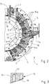
- a first embodiment of a fine mill 1 for crushing fibrous material is shown in a schematic cross section.
- the invention is not limited to a fine mill 1 for comminuting fibrous material, but also relates to fine mills for other applications.
- the fine mill 1, comprising a housing 2, a cutting rotor 3 with a plurality of uniformly distributed on its circumference cutting blades 4, a cutting rotor 3 surrounding the cutting stator 5 with a plurality of Statormessern 6, a Mahlguteinlass 7 for Mahlgutzuschreib or product inlet according to the arrow A. and a downstream in the direction of rotation of the cutting rotor 3 according to the arrow B after the Mahlguteinlass 7 discharge screen 8, which is firmly installed in the housing 2. All stator knives 6 are in the direction of rotation of the Cutting rotor 3 according to the arrow B between the Mahlguteinlass 7 and 8 Austragssieb arranged.
- Mahlguteinlass 7 represents a first Mahlguteinlass which is in the direction of rotation of the cutting rotor 3 according to the arrow B between the discharge screen 8 and the direction of rotation of the cutting rotor 3 according to the arrow B first stator blade 6.
- Another Mahlguteinlass 7a for Mahlgutzuschreib or the product inlet according to an arrow A ' is arranged in this first embodiment between the fourth direction in the direction of rotation of the cutting rotor 3 according to the arrow B and the fifth stator blade 6.
- the specific number and arrangement of the plurality of grinding inlets can be provided and / or used in an advantageous manner in coordination with the material to be ground and the grinding process and the grinding result.
- regrind is fed into the fine mill 1 through all the existing or, in the present case, just the two regrind inlets 7 and 7a to at least approximately equal proportions. It can be arranged further Mahlguteinlässe in the direction of rotation of the cutting rotor 3 according to the arrow B after the first Mahlguteinlass 7 and 8 before the Austragssieb.
- regrind is completely fed, in particular selectively, through a regrind inlet 7 or 7a into the fine mill 1, wherein both process variants can be realized by suitable control means in one and the same pulverizer 1.
- suitable control means including the corresponding structural requirements and requirements are readily known to those skilled in the art, so that it need not be discussed further here.
- the fine mill 1 according to the in Fig. 1 shown first embodiment further contains for each Mahlguteinlass 7, 7a a separate process gas inlet 9, 9a for process gas supply according to the arrow C or C '.
- the relation between the Mahlguteinlässen 7, 7a on the one hand and the process gas inlets 9, 9a on the other hand is such that the Mahlguteinlass 7, the process gas inlet 9 is associated, and that the Mahlguteinlass 7a associated with the process gas inlet 9a.
- the arrangement of the process gas inlets 9, 9a is such that each process gas inlet 9 is arranged in the direction of rotation of the cutting rotor 3 according to the arrow B in front of the associated Mahlguteinlass 7.
- corresponding process gas inlets can be assigned to each grinding material inlet or only to some grinding material inlets. Furthermore, at least one process gas inlet for supplying process gas can be arranged between the grinding material inlet 7 and the discharge screen 8 without being assigned to a further grinding material inlet.
- the fine mill 1 of the first embodiment according to the Fig. 1 a final wedge 10, which is assigned to the lying in the direction of rotation of the cutting rotor 3 according to the arrow B end of the Austragssiebes 8.
- This final wedge 10 is formed like a knife.
- the arrangement thus realized is such that in the direction of rotation of the cutting rotor 3 according to the arrow B on the discharge screen 8 in turn, the process gas inlet 9 for process gas supply according to the arrow C, the knife-like or knife-shaped final wedge 10 and then the first Mahlguteinlass 7 for Mahlgutzuschreib or are arranged to the product infeed according to the arrow A.
- a fine mill 1 which distributed a cutting rotor 3 with a variety of particular evenly on its circumference Cutting knives 4, a cutter rotor 5 surrounding the cutting rotor 3 with a plurality of Statormessern 6, a Mahlguteinlass 7 for Mahlgutzuschreib and a lying in the direction of rotation of the cutting rotor 3 according to the arrow B after the Mahlguteinlass 7 discharge screen 8, wherein according to the present invention, all the stator knives 6 arranged in the direction of rotation of the cutting rotor 3 between the Mahlguteinlass 7 and the discharge screen 8, and wherein at least two process gas inlets 9 are provided for process gas supply, the operating method may be such that process gas through all existing process gas inlets 9, 9a at least approximately equal proportions in the fine mill 1 is supplied.
- this method also applies to a refinement of the fine mill 1, wherein the first process gas inlet 9 is assigned to the first ground material inlet 7 and upstream in particular in the direction of rotation of the cutting rotor 3 according to the arrow B, and wherein all other process gas inlets 9a between the first ground material inlet 7 or the first process gas inlet 9 and the discharge screen 8 are arranged.
- FIG. 2 A second embodiment of a pulverizer 1 is shown in FIG. 2 in a schematic and with respect to the view of the first embodiment in the Fig. 1 shown partial cross-sectional view.
- the Fig. 3 shows in a likewise schematic cross-sectional view in an enlarged view a detail of the second embodiment according to the Fig. 2 ,
- the coolant lines 15 are designed and connected so that coolant, which may be a gas or a liquid, flows through the hollow shaped body 14.
- the hollow molded body 14 may be integrally formed in the housing 2 or directly in the cutting stator 5 or may constitute a separate component; in both cases, the cavity contained in the hollow molded body 14 for receiving the coolant and to realize its cooling effect
- the cavity contained in the hollow molded body 14 for receiving the coolant and to realize its cooling effect
- the invention is illustrated by way of example only and not by way of example with reference to the exemplary embodiments in the description and the drawing, but encompasses all variations, modifications, substitutions and combinations that the person skilled in the art can refer to the present documents within the scope of the claims.
Description
Die vorliegende Erfindung betrifft eine Feinmühle nach dem Oberbegriff des Anspruchs 1 und Betriebsverfahren dafür.The present invention relates to a fine mill according to the preamble of
Feinmühlen, wie z.B. Schneidmühlen, sind bekannt und dienen dem Zerkleinern von Kunststoffabfällen und entsprechenden schneidfähigen Stoffen in der Form von Fasern, Brocken, Hohlkörpern, Folien und Profilmaterial, aber auch von Natur- und Synthesekautschuk, vulkanisiertem Gummi, Kabelabfällen, Glasfaserabfällen, Leder oder Papier, um nur einige konkrete Beispiele anzugeben.Fine mills, e.g. Granulators, are known and serve to shred plastic waste and corresponding cutting materials in the form of fibers, chunks, hollow bodies, films and profile material, but also natural and synthetic rubber, vulcanized rubber, cable waste, glass fiber waste, leather or paper, just a few give specific examples.
Die
Die
Die vorliegende Erfindung hat das Ziel, eine Feinmühle und ein Betriebsverfahren dafür derart weiterzubilden, dass eine bessere und gleichmäßigere Mahlung von Mahlgut erreicht wird.The aim of the present invention is to develop a pulverizer and a method of operation therefor in such a way that a better and more uniform grinding of grinding stock is achieved.
Dieses Ziel wird mit einer Feinmühle nach dem Anspruch 1 und mit Betriebsverfahren für eine Feinmühle nach jeweils einem der Ansprüche 11, 13 oder 14 erreicht.This object is achieved with a fine mill according to
Damit ist bei einer gattungsgemäßen Feinmühle, die einen Schneidrotor mit einer Vielzahl von insbesondere gleichmäßig auf seinem Umfang verteilten Schneidmessern, einen den Schneidrotor umgebenden Schneidstator mit einer Mehrzahl von Statormessern, einen Mahlguteinlass zur Mahlgutzufuhr und einen in Drehrichtung des Schneidrotors nach dem Mahlguteinlass liegenden Austragssieb enthält, wobei weiter vorgesehen ist, dass sämtliche Statormesser in Drehrichtung des Schneidrotors zwischen dem Mahlguteinlass und dem Austragssieb angeordnet sind, erfindungsgemäß ferner vorgesehen, dass der Mahlguteinlass ein erster Mahlguteinlass ist, und dass in Drehrichtung des Schneidrotors nach dem ersten Mahlguteinlass und vor dem Austragssieb mindestens ein weiterer Mahlguteinlass zur Mahlgutzufuhr angeordnet ist, und dass jedem Mahlguteinlass ein eigener Prozessgaseinlass zur Prozessgaszufuhr zugeordnet ist.Thus, in a generic pulverizer containing a cutting rotor with a plurality of in particular uniformly distributed on its circumference cutting blades, a cutting rotor surrounding the cutting rotor with a plurality of Statormessern, a Mahlguteinlass for Mahlgutzufuhr and a lying in the direction of rotation of the cutting rotor after the Mahlguteinlass outlet sieve, wherein it is further provided that all stator knives are arranged in the direction of rotation of the cutting rotor between the Mahlguteinlass and the discharge screen, further provided according to the invention that the Mahlguteinlass is a first Mahlguteinlass, and that in the direction of rotation of the cutting rotor after the first Mahlguteinlass and before the discharge screen at least one other Mahlguteinlass is arranged for Mahlgutzufuhr, and that each Mahlguteinlass is assigned its own process gas inlet to the process gas supply.
Vorzugsweise kann bei einer solchen Feinmühle ferner vorgesehen sein, dass ein Gehäuse enthalten ist, in dem das Austragssieb fest eingebaut ist.Preferably, in such a fine mill further be provided that a housing is contained, in which the discharge screen is permanently installed.
Eine weitere bevorzugte Ausgestaltung ist darin zu sehen, dass in Drehrichtung des Schneidrotors nach dem ersten Mahlguteinlass und vor dem Austragssieb eine Mehrzahl von Mahlguteinlässen zur Mahlgutzufuhr angeordnet sein kann. Diese Varianten können dadurch weitergebildet sein, dass das Gehäuse vor dem in Drehrichtung des Schneidrotors nach dem ersten Mahlguteinlass liegenden zweiten Mahlguteinlass kühlbar ausgeführt ist, wobei außerdem vorzugsweise zur Kühlung des Gehäuses Kühleinrichtungen vorgesehen sind, die einen hohlen Formkörper vor dem zweiten Mahlguteinlass enthalten, und wobei ferner insbesondere die Kühleinrichtungen ausgelegt sind, so dass der hohle Formkörper von einem Gas oder einer Flüssigkeit durchströmt wird.A further preferred embodiment is to be seen in that in the direction of rotation of the cutting rotor after the first Mahlguteinlass and before the discharge screen a plurality of Mahlguteinlässen may be arranged for Mahlgutzufuhr. These variants can be further developed in that the housing is designed to be cool before the second Mahlguteinlass lying in the direction of rotation of the cutting rotor after the first Mahlguteinlass, wherein also preferably for cooling the housing cooling means are provided which contain a hollow molded body before the second Mahlguteinlass, and wherein Furthermore, in particular the cooling means are designed so that the hollow shaped body is flowed through by a gas or a liquid.
Noch eine andere vorzugsweise Ausgestaltung besteht darin, dass jeder Prozessgaseinlass in Drehrichtung des Schneidrotors vor dem zugehörigen Mahlguteinlass angeordnet sein kann.Yet another preferred embodiment is that each process gas inlet can be arranged in the direction of rotation of the cutting rotor in front of the associated Mahlguteinlass.
Eine weitere Ausgestaltung davon kann vorsehen, dass das Gehäuse vor dem in Drehrichtung des Schneidrotors nach dem ersten Prozessgaseinlass liegenden zweiten Prozessgaseinlass kühlbar ausgeführt ist, wobei weiter bevorzugt zur Kühlung des Gehäuses Kühleinrichtungen vorgesehen sind, einen hohlen Formkörper vor dem zweiten Prozessgaseinlass enthalten, und wobei insbesondere ferner die Kühleinrichtungen ausgelegt sind, so dass der hohle Formkörper von einem Gas oder einer Flüssigkeit durchströmt wird.A further embodiment of this may provide that the housing is designed to be coolable in front of the second process gas inlet lying in the direction of rotation of the cutting rotor after the first process gas inlet, more preferably being provided for cooling the housing cooling means, a hollow molded body before the second process gas inlet, and in particular Furthermore, the cooling means are designed so that the hollow shaped body is traversed by a gas or a liquid.
Es kann ferner mit Vorzug vorgesehen sein, dass wenigstens ein Prozessgaseinlass zur Prozessgaszufuhr zwischen dem ggf. ersten Mahlguteinlass und dem Austragssieb angeordnet ist.It can also be provided with preference that at least one process gas inlet for the process gas supply between the optionally first Mahlguteinlass and the discharge screen is arranged.
Gemäß noch einer weiteren bevorzugten Ausgestaltung kann dem in Drehrichtung des Schneidrotors liegenden Ende des Austragssiebes ein Abschlusskeil zugeordnet sein, wobei der Abschlusskeil mit Vorzug messerartig ausgebildet sein kann und/oder in Drehrichtung des Schneidrotors auf das Austragssieb folgend der Reihe nach ein Prozessgaseinlass zur Prozessgaszufuhr, der Abschlusskeil und dann der ggf. erste Mahlguteinlass angeordnet sein kann.According to yet another preferred embodiment, the end of the Austragssiebes lying in the direction of rotation of the discharge be assigned a final wedge, the final wedge may be knife-like preference and / or in the direction of rotation of the cutting rotor on the discharge following a series process gas inlet to the process gas supply, the Final wedge and then possibly the first Mahlguteinlass can be arranged.
Weiterhin kann vorzugsweise die Feinmühle zur Zerkleinerung von faserförmigem Gut ausgestaltet sein oder dienen.Furthermore, the fine mill may preferably be designed or used for comminution of fibrous material.
Durch die Erfindung wird zur Erreichung des obigen Ziels ferner ein Betriebsverfahren für eine vorstehend in ihren grundsätzlichen, bevorzugten und vorteilhaften Ausgestaltungen beschriebene Feinmühle geschaffen, wobei wenigstens zwei Prozessgaseinlässe zur Prozessgaszufuhr vorgesehen sind, und wobei ferner Prozessgas durch alle vorhandenen Prozessgaseinlässe zu wenigstens annähernd gleichen Anteilen in die Feinmühle zugeführt wird.The invention further provides an operating method for achieving the above object in a fine mill described above in its basic, preferred and advantageous embodiments, wherein at least two process gas inlets are provided for process gas supply, and further wherein process gas through all existing process gas inlets to at least approximately equal proportions the fine mill is supplied.
Eine bevorzugte weiterführende Ausgestaltung des vorstehenden Verfahrens kann dadurch erreicht werden, dass ein erster Prozessgaseinlass dem Mahlguteinlass zugeordnet und insbesondere in Drehrichtung des Schneidrotors vorgeschaltet ist, und dass alle anderen Prozessgaseinlässe zwischen dem Mahlguteinlass oder dem ersten Prozessgaseinlass und dem Austragssieb angeordnet sind.A preferred further embodiment of the above method can be achieved in that a first process gas inlet assigned to the grinding material inlet and upstream in particular in the direction of rotation of the cutting rotor, and that all other process gas inlets between the Mahlguteinlass or the first process gas inlet and the discharge screen are arranged.
Zur Erreichung des obigen Ziels schafft die Erfindung auch ein Betriebsverfahren für eine oben in ihren grundsätzlichen, bevorzugten und vorteilhaften Ausgestaltungen beschriebene Feinmühle, wobei Mahlgut durch alle vorhandenen Mahlguteinlässe zu wenigstens annähernd gleichen Anteilen in die Feinmühle zugeführt wird.To achieve the above object, the invention also provides an operating method for a fine mill described above in its basic, preferred and advantageous embodiments, wherein regrind through all existing Mahlguteinlässe to at least approximately equal proportions is fed into the fine mill.
Noch eine Alternative der Erfindung zur Erreichung des obigen Ziels besteht in einem Betriebsverfahren für eine oben in ihren grundsätzlichen, bevorzugten und vorteilhaften Ausgestaltungen beschriebene Feinmühle, wobei Mahlgut vollständig insbesondere wahlweise durch einen Mahlguteinlass in die Feinmühle zugeführt wird.Yet another alternative of the invention for achieving the above object is an operating method for a fine mill described above in its basic, preferred and advantageous embodiments, wherein the material to be ground is completely fed, in particular, optionally through a Mahlguteinlass in the fine mill.
Weitere bevorzugte und/oder vorteilhafte Ausgestaltungen der Erfindung ergeben sich aus den Ansprüchen und deren Kombinationen sowie den gesamten vorliegenden Anmeldungsunterlagen.Further preferred and / or advantageous embodiments of the invention will become apparent from the claims and their combinations as well as the entire present application documents.
Die Erfindung wird anhand von Ausführungsbeispielen nachfolgend unter Bezugnahme auf die Zeichnung lediglich exemplarisch näher erläutert, worin
-
Fig. 1 ein erstes Ausführungsbeispiel einer Feinmühle in einem schematischen Querschnitt zeigt, -
Fig. 2 ein zweites Ausführungsbeispiel einer Feinmühle in einem schematischen und teilweisen Querschnitt zeigt, und -
Fig. 3 ein Detail des zweiten Ausführungsbeispiels der Feinmühle gemäß derFig. 2 in einem schematischen Querschnitt zeigt.
-
Fig. 1 shows a first embodiment of a fine mill in a schematic cross section, -
Fig. 2 shows a second embodiment of a fine mill in a schematic and partial cross-section, and -
Fig. 3 a detail of the second embodiment of the fine mill according to theFig. 2 in a schematic cross section shows.
Anhand der nachfolgend beschriebenen und in den Zeichnungen dargestellten Ausführungs- und Anwendungsbeispiele wird die Erfindung lediglich exemplarisch näher erläutert, d.h. sie ist nicht auf diese Ausführungs- und Anwendungsbeispiele oder auf die jeweiligen Merkmalskombinationen innerhalb dieser Ausführungs- und Anwendungsbeispiele beschränkt. Verfahrens- und Vorrichtungsmerkmale ergeben sich jeweils analog auch aus Vorrichtungs- bzw. Verfahrensbeschreibungen.With reference to the embodiments and application examples described below and illustrated in the drawings, the invention will be explained only by way of example, ie it is not limited to these embodiments and applications or to the respective feature combinations within these embodiments and applications. Procedural and Device features also result analogously from device or process descriptions.
Einzelne Merkmale, die im Zusammenhang mit einem konkreten Ausführungsbeispiel angeben und/oder dargestellt sind, sind nicht auf dieses Ausführungsbeispiel oder die Kombination mit den übrigen Merkmalen dieses Ausführungsbeispiels beschränkt, sondern können im Rahmen des technisch Möglichen mit anderen Ausführungs- und Anwendungsbeispielen oder einzelnen Merkmalen und Merkmalskombinationen davon und/oder jeglichen vorbekannten Varianten, auch wenn sie in den vorliegenden Unterlagen nicht gesondert behandelt sind, kombiniert werden.Individual features that are specified and / or illustrated in connection with a specific embodiment, are not limited to this embodiment or the combination with the other features of this embodiment, but may in the context of the technically possible with other embodiments and applications or individual features and Feature combinations thereof and / or any known variants, even if they are not treated separately in the present documents, combined.
Anhand der Darstellungen in der Zeichnung werden auch solche Merkmale deutlich, die nicht mit Bezugszeichen versehen sind, unabhängig davon, ob solche Merkmale nachfolgend beschrieben sind oder nicht. Andererseits sind auch Merkmale, die in der vorliegenden Beschreibung enthalten, aber nicht in der Zeichnung sichtbar oder dargestellt sind, ohne weiteres für einen Fachmann verständlich.On the basis of the representations in the drawing, those features are also clear, which are not provided with reference numerals, regardless of whether such features are described below or not. On the other hand, features that are included in the present description but are not visible or illustrated in the drawing will be readily understood by those skilled in the art.
In der
Bei der in der
Verfahrensmäßig ist dabei vorgesehen, dass Mahlgut durch alle vorhandenen oder im vorliegenden Fall eben die beiden Mahlguteinlässe 7 und 7a zu wenigstens annähernd gleichen Anteilen in die Feinmühle 1 zugeführt wird. Es können weitere Mahlguteinlässe in Drehrichtung des Schneidrotors 3 gemäß dem Pfeil B nach dem ersten Mahlguteinlass 7 und vor dem Austragssieb 8 angeordnet sein. Als alternative Verfahrensgestaltung kann aber auch vorgesehen sein, dass Mahlgut vollständig insbesondere wahlweise durch einen Mahlguteinlass 7 oder 7a in die Feinmühle 1 zugeführt wird, wobei beide Verfahrensvarianten durch geeignete Steuermöglichkeiten bei ein und derselben Feinmühle 1 realisierbar sein können. Derartige Steuermöglichkeiten inklusive der entsprechenden baulichen Voraussetzungen und Erfordernisse sind dem Fachmann ohne weiteres bekannt, so dass darauf hier nicht weiter eingegangen werden braucht.In terms of method, it is provided that regrind is fed into the
Die Feinmühle 1 gemäß dem in der
Weiterhin enthält die Feinmühle 1 des ersten Ausführungsbeispiels gemäß der
Neben den schon weiter oben erläuterten Ausgestaltungsmöglichkeiten des Betriebsverfahrens für eine Feinmühle 1 gemäß der vorliegenden Erfindung werden noch weitere Verfahrensvarianten geschaffen.In addition to the above-described embodiment possibilities of the operating method for a
Bei einer Feinmühle 1, die einen Schneidrotor 3 mit einer Vielzahl von insbesondere gleichmäßig auf seinem Umfang verteilten Schneidmessern 4, einen den Schneidrotor 3 umgebenden Schneidstator 5 mit einer Mehrzahl von Statormessern 6, einen Mahlguteinlass 7 zur Mahlgutzufuhr und einen in Drehrichtung des Schneidrotors 3 gemäß dem Pfeil B nach dem Mahlguteinlass 7 liegenden Austragssieb 8 enthält, wobei gemäß der vorliegenden Erfindung sämtliche Statormesser 6 in Drehrichtung des Schneidrotors 3 zwischen dem Mahlguteinlass 7 und dem Austragssieb 8 angeordnet sind, und wobei wenigstens zwei Prozessgaseinlässe 9 zur Prozessgaszufuhr vorgesehen sind, kann das Betriebsverfahren derart sein, dass Prozessgas durch alle vorhandenen Prozessgaseinlässe 9, 9a zu wenigstens annähernd gleichen Anteilen in die Feinmühle 1 zugeführt wird. Dieses Verfahren gilt in einer entsprechenden Variante auch für eine Ausgestaltung der Feinmühle 1, wobei der erste Prozessgaseinlass 9 dem ersten Mahlguteinlass 7 zugeordnet und insbesondere in Drehrichtung des Schneidrotors 3 gemäß dem Pfeil B vorgeschaltet ist, und wobei alle anderen Prozessgaseinlässe 9a zwischen dem ersten Mahlguteinlass 7 oder dem ersten Prozessgaseinlass 9 und dem Austragssieb 8 angeordnet sind.In a
Der Vollständigkeit halber wird noch auf einen Nebenlufteinlass 11 zum Eintritt von Nebenluft gemäß dem Pfeil D und einen Produktauslass 12 zum Produktauslauf gemäß dem Pfeil E hingewiesen, die entsprechend der Darstellung in der
Ein zweites Ausführungsbeispiel einer Feinmühle 1 ist in der Fi.g. 2 in einer schematischen und bezüglich der Ansicht des erstens Ausführungsbeispiels in der
Soweit bei dem zweiten Ausführungsbeispiel gemäß der
Zusätzlich zu den Merkmalen des erstens Ausführungsbeispiels gemäß der
Die Erfindung ist anhand der Ausführungsbeispiele in der Beschreibung und in der Zeichnung lediglich exemplarisch dargestellt und nicht darauf beschränkt, sondern umfasst alle Variationen, Modifikationen, Substitutionen und Kombinationen, die der Fachmann den vorliegenden Unterlagen im Rahmen der Ansprüche entnehmen kann.In addition to the features of the first embodiment according to the
The invention is illustrated by way of example only and not by way of example with reference to the exemplary embodiments in the description and the drawing, but encompasses all variations, modifications, substitutions and combinations that the person skilled in the art can refer to the present documents within the scope of the claims.
Claims (14)
- Grinding mill (1), comprising a cutting rotor (3) with a plurality of cutting blades (4) distributed in particular evenly on its circumference, a cutting stator (5) with a plurality of stator blades (6) surrounding the cutting rotor (3), a grinding stock inlet (7) for charging the grinding stock and a discharge screen (8) situated in the direction of rotation of the cutting rotor (3) downstream of the grinding stock inlet (7),
wherein all the stator blades (6) are arranged in the direction of rotation of the cutting rotor (3) between the grinding stock inlet (7) and the discharge screen (8),
characterized in that the grinding stock inlet (7) is a first grinding stock inlet (7), and in that at least one further grinding stock inlet (7a) for charging the grinding stock is arranged in the direction of rotation of the cutting rotor (3) downstream of the first grinding stock inlet (7) and upstream of the discharge screen (8), and in that a separate process gas inlet (9, 9a) is assigned to each grinding stock inlet (7, 7a) for supplying process gas. - Grinding mill (1) according to claim 1, characterized in that it comprises a housing (2) in which the discharge screen (8) is permanently installed.
- Grinding mill (1) according to claim 1 or claim 2,
characterized in that in the direction of rotation of the cutting rotor (3) downstream of the first grinding stock inlet (7) and upstream of the discharge screen (8) a plurality of grinding stock inlets (7a) is provided for charging the grinding stock. - Grinding mill (1) according to any one of the preceding claims, characterized in that the housing (2) is constructed to be coolable upstream of the second grinding stock inlet (7a) downstream of the first grinding stock inlet (7) in the direction of rotation of the cutting rotor (3).
- Grinding mill (1) according to claim 4, characterized in that cooling devices (13) for cooling the housing (2) comprise hollow moulded bodies (14, 14a) upstream of the second grinding stock inlet (7a).
- Grinding mill (1) according to claim 5, characterized in that the cooling devices (13) are designed so that a gas or liquid flows through the hollow moulded bodies (14, 14a).
- Grinding mill (1) according to claim 4, characterized in that at least one process gas inlet (9a) for the supply of process gas is provided between any first grinding stock inlet (7) and the discharge screen (8).
- Grinding mill (1) according to claim 1, characterized in that a sealing wedge (10) is assigned to the end of the discharge screen (8) situated in the direction of rotation of the cutting rotor (3).
- Grinding mill (1) according to claim 8, characterized in that the sealing wedge (10) is blade-like in design.
- Grinding mill (1) according to claim 8 or claim 9,
characterized in that a process gas inlet (9) for supplying process gas, the sealing wedge (10) and then any first grinding stock inlet (7) present are sequentially arranged in the direction of rotation of the cutting rotor (3) downstream of the discharge screen (8). - Operating method for a grinding mill (1) according to any one of claims 1 to 10, wherein at least two process gas inlets (9, 9a) are provided for the supply of process gas, characterized in that process gas is fed into the grinding mill (1) via all existing process gas inlets (9, 9a) in at least approximately equal portions.
- Operating method for a grinding mill (1) according to claim 11, characterized in that a first process gas inlet (9) is assigned to the grinding stock inlet (7) and in particular is situated upstream in the direction of rotation of the cutting rotor (3), and in that all other process gas inlets (9a) are arranged between the grinding stock inlet (7), or the first process gas inlet (9), and the discharge screen (8).
- Operating method for a grinding mill (1) according to any one of claims 1 to 10, characterized in that grinding stock is fed into the grinding mill (1) via all existing grinding stock inlets (7, 7a) in at least approximately equal portions.
- Operating method for a grinding mill (1) according to any one of claims 1 to 10, characterized in that grinding stock is fed into the grinding mill (1) complete, particularly optionally via a grinding stock inlet (7 or 7a) .
Priority Applications (1)
| Application Number | Priority Date | Filing Date | Title |
|---|---|---|---|
| PL09013727T PL2191901T3 (en) | 2008-11-26 | 2009-10-31 | Pulveriser and method for operating same |
Applications Claiming Priority (2)
| Application Number | Priority Date | Filing Date | Title |
|---|---|---|---|
| DE102008059114 | 2008-11-26 | ||
| DE102009012743A DE102009012743A1 (en) | 2008-11-26 | 2009-03-12 | Fine mill and operating method for it |
Publications (3)
| Publication Number | Publication Date |
|---|---|
| EP2191901A2 EP2191901A2 (en) | 2010-06-02 |
| EP2191901A3 EP2191901A3 (en) | 2015-11-04 |
| EP2191901B1 true EP2191901B1 (en) | 2018-12-05 |
Family
ID=42114735
Family Applications (1)
| Application Number | Title | Priority Date | Filing Date |
|---|---|---|---|
| EP09013727.4A Active EP2191901B1 (en) | 2008-11-26 | 2009-10-31 | Pulveriser and method for operating same |
Country Status (8)
| Country | Link |
|---|---|
| US (2) | US8800901B2 (en) |
| EP (1) | EP2191901B1 (en) |
| JP (1) | JP5425598B2 (en) |
| CN (1) | CN101733181B (en) |
| BR (1) | BRPI0904482B1 (en) |
| DE (1) | DE102009012743A1 (en) |
| ES (1) | ES2713248T3 (en) |
| PL (1) | PL2191901T3 (en) |
Families Citing this family (22)
| Publication number | Priority date | Publication date | Assignee | Title |
|---|---|---|---|---|
| US8500048B2 (en) * | 2008-07-14 | 2013-08-06 | Cake Energy, Llc | Process and apparatus for drying and powderizing material |
| JP5860290B2 (en) * | 2012-01-12 | 2016-02-16 | 株式会社ブリヂストン | Method and apparatus for producing rubber material with reduced impurity content |
| CN103723456A (en) * | 2013-12-13 | 2014-04-16 | 广西奥士达环境工程有限公司 | Impeller of unloader |
| US10471512B2 (en) * | 2014-06-16 | 2019-11-12 | Commonwealth Scientific And Industrial Research Organisation | Method of producing a powder product |
| CN105341976A (en) * | 2015-11-30 | 2016-02-24 | 无锡市双氏机械有限公司 | Bubble mixing and rolling type feed processing machine |
| CN105361221A (en) * | 2015-11-30 | 2016-03-02 | 无锡市双氏机械有限公司 | Circulation cutting type discharging stirring type feed mixed processing device |
| CN105310094A (en) * | 2015-11-30 | 2016-02-10 | 无锡市双氏机械有限公司 | Novel cutting type feed mixing and processing device |
| CN105771775A (en) * | 2015-11-30 | 2016-07-20 | 无锡市双氏机械有限公司 | Bubble type mixed-rolling screening feed mixer |
| CN105286053A (en) * | 2015-11-30 | 2016-02-03 | 无锡市双氏机械有限公司 | Circulating cutting and mixing type feed processing device |
| CN105341968A (en) * | 2015-11-30 | 2016-02-24 | 无锡市双氏机械有限公司 | Heat preservation type feed processing device in flowing, circulating and cutting manner |
| CN105326077A (en) * | 2015-11-30 | 2016-02-17 | 无锡市双氏机械有限公司 | Efficient feeding heat preservation type fodder mixing processing device |
| CN105326082A (en) * | 2015-11-30 | 2016-02-17 | 无锡市双氏机械有限公司 | Efficient-feeding cutting mixing fodder processing machine |
| CN105326081A (en) * | 2015-11-30 | 2016-02-17 | 无锡市双氏机械有限公司 | Multifunctional feed mixing and processing device |
| CN105964359A (en) * | 2016-06-16 | 2016-09-28 | 成都迅德科技有限公司 | Crusher |
| CN107371656A (en) * | 2017-09-21 | 2017-11-24 | 苏州仁益生物科技有限公司 | A kind of agricultural uses stalk dust-free pulverizing mill tool |
| CN107899696A (en) * | 2017-11-02 | 2018-04-13 | 中国矿业大学 | A kind of copper rice machine reducing mechanism crushed for waste and old cable |
| CN109463142B (en) * | 2018-10-18 | 2020-10-16 | 苏州元联科技创业园管理有限公司 | Pulverizer capable of cooling in production |
| CN110773256B (en) * | 2019-11-06 | 2021-12-10 | 营口仁威矿产有限公司 | Multi-stage crusher for refractory material |
| CN111250196A (en) * | 2020-01-16 | 2020-06-09 | 胡培花 | Destroying device for waste household communication equipment |
| DK3909682T3 (en) * | 2020-05-14 | 2022-07-04 | Pfeiffer Se Gebr | Method and roller mill for thermomechanical activation of a clay mixture |
| CN113399019B (en) * | 2021-05-10 | 2022-12-06 | 龚雯静 | Traditional chinese medical science spleen and stomach branch of academic or vocational study medicine reducing mechanism |
| CN114588988B (en) * | 2022-03-15 | 2023-06-02 | 安徽龙钰徽派古建工艺制品有限公司 | Archaize building brick and tile processing equipment prepared from building waste |
Citations (4)
| Publication number | Priority date | Publication date | Assignee | Title |
|---|---|---|---|---|
| US4239160A (en) * | 1979-05-17 | 1980-12-16 | E. I. Du Pont De Nemours And Company | Film shredder |
| US4241881A (en) * | 1979-07-12 | 1980-12-30 | Kimberly-Clark Corporation | Fiber separation from pulp sheet stacks |
| JPH08257428A (en) * | 1995-03-22 | 1996-10-08 | Fuji Photo Film Co Ltd | Pulverizer for photographic processing composition container |
| JP2000084429A (en) * | 1998-09-09 | 2000-03-28 | Sanriki Seisakusho:Kk | Crusher |
Family Cites Families (22)
| Publication number | Priority date | Publication date | Assignee | Title |
|---|---|---|---|---|
| US1423867A (en) * | 1921-12-27 | 1922-07-25 | Mitts & Merrill | Cutting machine |
| US1917198A (en) * | 1931-08-21 | 1933-07-04 | Chas Hollenbach Inc | Comminuting machine |
| NL112297C (en) * | 1956-12-17 | |||
| DE2544496A1 (en) * | 1975-10-04 | 1977-04-14 | Bruderhaus Maschinen Gmbh | CUTTER MILL |
| CA1035657A (en) * | 1976-01-23 | 1978-08-01 | Carl H. Kersey | Independently mounted thresher cutters |
| DE2624415B1 (en) * | 1976-05-31 | 1978-03-16 | Automatik App Maschb H Hench G | Device for granulating streams of thermoplastics, elastomers or similar materials |
| DE2632330C2 (en) * | 1976-07-17 | 1983-04-07 | Neue Bruderhaus Maschinenfabrik GmbH, 7410 Reutlingen | Granulator |
| JPS61111149A (en) * | 1984-11-05 | 1986-05-29 | 三菱重工業株式会社 | Explosion-proof type coarse dust crusher |
| DE3440993A1 (en) * | 1984-11-09 | 1986-05-22 | Omya GmbH, 5000 Köln | AGITATOR MILL, ESPECIALLY AGITATOR BALL MILL |
| JPS61220745A (en) * | 1985-03-27 | 1986-10-01 | ダイアホイル株式会社 | Crushing apparatus |
| JPH0111034Y2 (en) * | 1986-11-11 | 1989-03-30 | ||
| US5402948A (en) * | 1993-04-30 | 1995-04-04 | Kaczmarek; Al | Comminuting device with face |
| US5971305A (en) * | 1997-07-21 | 1999-10-26 | Davenport; Ricky W. | Rotary shredder |
| AT406344B (en) * | 1998-06-17 | 2000-04-25 | Bacher Helmut | Single shaft shredder, e.g. FOR PLASTIC OR WOOD |
| DE19954998A1 (en) | 1999-11-16 | 2001-05-17 | Roland Nied | Cutting mill has cutting rotor and cylindrical classifying device rotating about axes displaced from one another and parallel, with opposed directions of rotation |
| DE19961882A1 (en) * | 1999-12-20 | 2001-06-28 | Getecha Ges Fuer Tech Anlagen | Comminuter for plastics has a rugged, simple integral sieve and stator |
| US6749138B2 (en) * | 2002-03-05 | 2004-06-15 | Phoenix Technologies, L.P. | Granulator |
| DE10222814B4 (en) * | 2002-05-21 | 2007-05-03 | Nuga AG Kunststoffschneidemühlen | Method for operating a knife mill for comminuting plastic material and knife mill operating according to the method |
| CN2696088Y (en) * | 2004-05-13 | 2005-04-27 | 李根铭 | Special equipment for regenerating and using waste wire and cable |
| DE102005023567A1 (en) * | 2005-05-18 | 2006-11-23 | Netzsch-Feinmahltechnik Gmbh | Fibrous and non-fibrous products cutting method e.g. for cellulose products, involves having cutter for cutting up of fibrous or non-fibrous products with blade roller and knife |
| DE202005008077U1 (en) * | 2005-05-19 | 2006-10-05 | Doppstadt Calbe Gmbh | comminution device |
| JP4835744B2 (en) * | 2009-10-16 | 2011-12-14 | 有限会社吉工 | Crusher |
-
2009
- 2009-03-12 DE DE102009012743A patent/DE102009012743A1/en not_active Withdrawn
- 2009-10-31 EP EP09013727.4A patent/EP2191901B1/en active Active
- 2009-10-31 PL PL09013727T patent/PL2191901T3/en unknown
- 2009-10-31 ES ES09013727T patent/ES2713248T3/en active Active
- 2009-11-25 BR BRPI0904482-5A patent/BRPI0904482B1/en active IP Right Grant
- 2009-11-25 JP JP2009268131A patent/JP5425598B2/en active Active
- 2009-11-25 US US12/626,317 patent/US8800901B2/en active Active
- 2009-11-26 CN CN200910224970.9A patent/CN101733181B/en active Active
-
2012
- 2012-04-27 US US13/458,283 patent/US20120211576A1/en not_active Abandoned
Patent Citations (4)
| Publication number | Priority date | Publication date | Assignee | Title |
|---|---|---|---|---|
| US4239160A (en) * | 1979-05-17 | 1980-12-16 | E. I. Du Pont De Nemours And Company | Film shredder |
| US4241881A (en) * | 1979-07-12 | 1980-12-30 | Kimberly-Clark Corporation | Fiber separation from pulp sheet stacks |
| JPH08257428A (en) * | 1995-03-22 | 1996-10-08 | Fuji Photo Film Co Ltd | Pulverizer for photographic processing composition container |
| JP2000084429A (en) * | 1998-09-09 | 2000-03-28 | Sanriki Seisakusho:Kk | Crusher |
Also Published As
| Publication number | Publication date |
|---|---|
| JP2010125452A (en) | 2010-06-10 |
| EP2191901A2 (en) | 2010-06-02 |
| US8800901B2 (en) | 2014-08-12 |
| CN101733181A (en) | 2010-06-16 |
| BRPI0904482B1 (en) | 2019-10-01 |
| BRPI0904482A2 (en) | 2010-11-03 |
| US20120211576A1 (en) | 2012-08-23 |
| JP5425598B2 (en) | 2014-02-26 |
| ES2713248T3 (en) | 2019-05-20 |
| CN101733181B (en) | 2015-07-15 |
| DE102009012743A1 (en) | 2010-05-27 |
| PL2191901T3 (en) | 2019-06-28 |
| US20100127105A1 (en) | 2010-05-27 |
| EP2191901A3 (en) | 2015-11-04 |
Similar Documents
| Publication | Publication Date | Title |
|---|---|---|
| EP2191901B1 (en) | Pulveriser and method for operating same | |
| EP0624444B1 (en) | Process and device for preparing polyurethane foam scrap | |
| DE102010045125A1 (en) | Device for crushing feedstock | |
| EP2987557B1 (en) | Grinding machine for grinding of a product | |
| DE102009060523A1 (en) | Crushing device with counter knife device | |
| DE2256524A1 (en) | PROCESS AND DEVICE FOR CRUSHING GOOD IN SMALL PIECES | |
| EP1909976A2 (en) | Screening device | |
| EP2065092B1 (en) | Device and method of releasing the composite of a feeder product in a composite | |
| EP0387868B1 (en) | Shredding apparatus for waste wood | |
| WO2001043878A1 (en) | Device for comminuting a good to be comminuted | |
| DE202014000870U1 (en) | comminution device | |
| DE2444657A1 (en) | SHREDDING DEVICE WITH A CENTRIFUGAL CLASSIFIER | |
| EP2054156B1 (en) | Roller mill | |
| EP3248688B1 (en) | Knife for a shredding machine | |
| AT502846A1 (en) | DEVICE FOR PREPARING PLASTIC WASTE | |
| EP1448303B1 (en) | Tube grinder and method for comminuting lumpy grinding stock | |
| DE10137008C1 (en) | Wood chip production method has wood chips of reduced size separated out via sieve with defined sieve openings | |
| DE4307230A1 (en) | Process and plant for comminuting the bed of brittle regrind | |
| DE10113953C1 (en) | Device for shredding plastic structures with a low material thickness | |
| DE3908395A1 (en) | Device for disintegrating leftover and waste wood | |
| DE3416009A1 (en) | Machine for the comminution of maize, CCM or moist grain and process for the use of the machine | |
| WO2014173384A1 (en) | Device for comminuting fragmented residual products from a palm oil extraction process | |
| DE202017000378U1 (en) | Knife drum for shredding wood | |
| DE19752803C1 (en) | Cutter for wood chipper | |
| DE202018002430U1 (en) | Knife drum and shredder for shredding wood |
Legal Events
| Date | Code | Title | Description |
|---|---|---|---|
| PUAI | Public reference made under article 153(3) epc to a published international application that has entered the european phase |
Free format text: ORIGINAL CODE: 0009012 |
|
| AK | Designated contracting states |
Kind code of ref document: A2 Designated state(s): AT BE BG CH CY CZ DE DK EE ES FI FR GB GR HR HU IE IS IT LI LT LU LV MC MK MT NL NO PL PT RO SE SI SK SM TR |
|
| AX | Request for extension of the european patent |
Extension state: AL BA RS |
|
| RAP1 | Party data changed (applicant data changed or rights of an application transferred) |
Owner name: NETZSCH TROCKENMAHLTECHNIK GMBH Owner name: NIED, ROLAND, DR.-ING. |
|
| PUAL | Search report despatched |
Free format text: ORIGINAL CODE: 0009013 |
|
| AK | Designated contracting states |
Kind code of ref document: A3 Designated state(s): AT BE BG CH CY CZ DE DK EE ES FI FR GB GR HR HU IE IS IT LI LT LU LV MC MK MT NL NO PL PT RO SE SI SK SM TR |
|
| AX | Request for extension of the european patent |
Extension state: AL BA RS |
|
| RIC1 | Information provided on ipc code assigned before grant |
Ipc: B02C 18/14 20060101AFI20151001BHEP Ipc: B02C 18/18 20060101ALI20151001BHEP Ipc: B02C 23/16 20060101ALI20151001BHEP |
|
| 17P | Request for examination filed |
Effective date: 20160422 |
|
| RBV | Designated contracting states (corrected) |
Designated state(s): AT BE BG CH CY CZ DE DK EE ES FI FR GB GR HR HU IE IS IT LI LT LU LV MC MK MT NL NO PL PT RO SE SI SK SM TR |
|
| 17Q | First examination report despatched |
Effective date: 20160908 |
|
| STAA | Information on the status of an ep patent application or granted ep patent |
Free format text: STATUS: EXAMINATION IS IN PROGRESS |
|
| GRAP | Despatch of communication of intention to grant a patent |
Free format text: ORIGINAL CODE: EPIDOSNIGR1 |
|
| STAA | Information on the status of an ep patent application or granted ep patent |
Free format text: STATUS: GRANT OF PATENT IS INTENDED |
|
| INTG | Intention to grant announced |
Effective date: 20171211 |
|
| GRAS | Grant fee paid |
Free format text: ORIGINAL CODE: EPIDOSNIGR3 |
|
| GRAJ | Information related to disapproval of communication of intention to grant by the applicant or resumption of examination proceedings by the epo deleted |
Free format text: ORIGINAL CODE: EPIDOSDIGR1 |
|
| GRAL | Information related to payment of fee for publishing/printing deleted |
Free format text: ORIGINAL CODE: EPIDOSDIGR3 |
|
| STAA | Information on the status of an ep patent application or granted ep patent |
Free format text: STATUS: EXAMINATION IS IN PROGRESS |
|
| GRAP | Despatch of communication of intention to grant a patent |
Free format text: ORIGINAL CODE: EPIDOSNIGR1 |
|
| STAA | Information on the status of an ep patent application or granted ep patent |
Free format text: STATUS: GRANT OF PATENT IS INTENDED |
|
| INTC | Intention to grant announced (deleted) | ||
| INTG | Intention to grant announced |
Effective date: 20180511 |
|
| GRAA | (expected) grant |
Free format text: ORIGINAL CODE: 0009210 |
|
| GRAA | (expected) grant |
Free format text: ORIGINAL CODE: 0009210 |
|
| STAA | Information on the status of an ep patent application or granted ep patent |
Free format text: STATUS: THE PATENT HAS BEEN GRANTED |
|
| AK | Designated contracting states |
Kind code of ref document: B1 Designated state(s): AT BE BG CH CY CZ DE DK EE ES FI FR GB GR HR HU IE IS IT LI LT LU LV MC MK MT NL NO PL PT RO SE SI SK SM TR |
|
| REG | Reference to a national code |
Ref country code: GB Ref legal event code: FG4D Free format text: NOT ENGLISH |
|
| REG | Reference to a national code |
Ref country code: CH Ref legal event code: EP |
|
| REG | Reference to a national code |
Ref country code: AT Ref legal event code: REF Ref document number: 1072390 Country of ref document: AT Kind code of ref document: T Effective date: 20181215 |
|
| REG | Reference to a national code |
Ref country code: IE Ref legal event code: FG4D Free format text: LANGUAGE OF EP DOCUMENT: GERMAN |
|
| REG | Reference to a national code |
Ref country code: DE Ref legal event code: R096 Ref document number: 502009015486 Country of ref document: DE |
|
| REG | Reference to a national code |
Ref country code: SE Ref legal event code: TRGR |
|
| REG | Reference to a national code |
Ref country code: NL Ref legal event code: MP Effective date: 20181205 |
|
| REG | Reference to a national code |
Ref country code: LT Ref legal event code: MG4D |
|
| PG25 | Lapsed in a contracting state [announced via postgrant information from national office to epo] |
Ref country code: LV Free format text: LAPSE BECAUSE OF FAILURE TO SUBMIT A TRANSLATION OF THE DESCRIPTION OR TO PAY THE FEE WITHIN THE PRESCRIBED TIME-LIMIT Effective date: 20181205 Ref country code: HR Free format text: LAPSE BECAUSE OF FAILURE TO SUBMIT A TRANSLATION OF THE DESCRIPTION OR TO PAY THE FEE WITHIN THE PRESCRIBED TIME-LIMIT Effective date: 20181205 Ref country code: NO Free format text: LAPSE BECAUSE OF FAILURE TO SUBMIT A TRANSLATION OF THE DESCRIPTION OR TO PAY THE FEE WITHIN THE PRESCRIBED TIME-LIMIT Effective date: 20190305 Ref country code: LT Free format text: LAPSE BECAUSE OF FAILURE TO SUBMIT A TRANSLATION OF THE DESCRIPTION OR TO PAY THE FEE WITHIN THE PRESCRIBED TIME-LIMIT Effective date: 20181205 Ref country code: BG Free format text: LAPSE BECAUSE OF FAILURE TO SUBMIT A TRANSLATION OF THE DESCRIPTION OR TO PAY THE FEE WITHIN THE PRESCRIBED TIME-LIMIT Effective date: 20190305 |
|
| REG | Reference to a national code |
Ref country code: ES Ref legal event code: FG2A Ref document number: 2713248 Country of ref document: ES Kind code of ref document: T3 Effective date: 20190520 |
|
| PG25 | Lapsed in a contracting state [announced via postgrant information from national office to epo] |
Ref country code: GR Free format text: LAPSE BECAUSE OF FAILURE TO SUBMIT A TRANSLATION OF THE DESCRIPTION OR TO PAY THE FEE WITHIN THE PRESCRIBED TIME-LIMIT Effective date: 20190306 |
|
| PG25 | Lapsed in a contracting state [announced via postgrant information from national office to epo] |
Ref country code: NL Free format text: LAPSE BECAUSE OF FAILURE TO SUBMIT A TRANSLATION OF THE DESCRIPTION OR TO PAY THE FEE WITHIN THE PRESCRIBED TIME-LIMIT Effective date: 20181205 |
|
| PG25 | Lapsed in a contracting state [announced via postgrant information from national office to epo] |
Ref country code: IT Free format text: LAPSE BECAUSE OF FAILURE TO SUBMIT A TRANSLATION OF THE DESCRIPTION OR TO PAY THE FEE WITHIN THE PRESCRIBED TIME-LIMIT Effective date: 20181205 Ref country code: CZ Free format text: LAPSE BECAUSE OF FAILURE TO SUBMIT A TRANSLATION OF THE DESCRIPTION OR TO PAY THE FEE WITHIN THE PRESCRIBED TIME-LIMIT Effective date: 20181205 Ref country code: PT Free format text: LAPSE BECAUSE OF FAILURE TO SUBMIT A TRANSLATION OF THE DESCRIPTION OR TO PAY THE FEE WITHIN THE PRESCRIBED TIME-LIMIT Effective date: 20190405 |
|
| PG25 | Lapsed in a contracting state [announced via postgrant information from national office to epo] |
Ref country code: RO Free format text: LAPSE BECAUSE OF FAILURE TO SUBMIT A TRANSLATION OF THE DESCRIPTION OR TO PAY THE FEE WITHIN THE PRESCRIBED TIME-LIMIT Effective date: 20181205 Ref country code: IS Free format text: LAPSE BECAUSE OF FAILURE TO SUBMIT A TRANSLATION OF THE DESCRIPTION OR TO PAY THE FEE WITHIN THE PRESCRIBED TIME-LIMIT Effective date: 20190405 Ref country code: EE Free format text: LAPSE BECAUSE OF FAILURE TO SUBMIT A TRANSLATION OF THE DESCRIPTION OR TO PAY THE FEE WITHIN THE PRESCRIBED TIME-LIMIT Effective date: 20181205 Ref country code: SM Free format text: LAPSE BECAUSE OF FAILURE TO SUBMIT A TRANSLATION OF THE DESCRIPTION OR TO PAY THE FEE WITHIN THE PRESCRIBED TIME-LIMIT Effective date: 20181205 Ref country code: SK Free format text: LAPSE BECAUSE OF FAILURE TO SUBMIT A TRANSLATION OF THE DESCRIPTION OR TO PAY THE FEE WITHIN THE PRESCRIBED TIME-LIMIT Effective date: 20181205 |
|
| REG | Reference to a national code |
Ref country code: DE Ref legal event code: R097 Ref document number: 502009015486 Country of ref document: DE |
|
| PLBE | No opposition filed within time limit |
Free format text: ORIGINAL CODE: 0009261 |
|
| STAA | Information on the status of an ep patent application or granted ep patent |
Free format text: STATUS: NO OPPOSITION FILED WITHIN TIME LIMIT |
|
| PG25 | Lapsed in a contracting state [announced via postgrant information from national office to epo] |
Ref country code: SI Free format text: LAPSE BECAUSE OF FAILURE TO SUBMIT A TRANSLATION OF THE DESCRIPTION OR TO PAY THE FEE WITHIN THE PRESCRIBED TIME-LIMIT Effective date: 20181205 Ref country code: DK Free format text: LAPSE BECAUSE OF FAILURE TO SUBMIT A TRANSLATION OF THE DESCRIPTION OR TO PAY THE FEE WITHIN THE PRESCRIBED TIME-LIMIT Effective date: 20181205 |
|
| 26N | No opposition filed |
Effective date: 20190906 |
|
| PG25 | Lapsed in a contracting state [announced via postgrant information from national office to epo] |
Ref country code: TR Free format text: LAPSE BECAUSE OF FAILURE TO SUBMIT A TRANSLATION OF THE DESCRIPTION OR TO PAY THE FEE WITHIN THE PRESCRIBED TIME-LIMIT Effective date: 20181205 |
|
| PG25 | Lapsed in a contracting state [announced via postgrant information from national office to epo] |
Ref country code: MC Free format text: LAPSE BECAUSE OF FAILURE TO SUBMIT A TRANSLATION OF THE DESCRIPTION OR TO PAY THE FEE WITHIN THE PRESCRIBED TIME-LIMIT Effective date: 20181205 |
|
| REG | Reference to a national code |
Ref country code: CH Ref legal event code: PL |
|
| PG25 | Lapsed in a contracting state [announced via postgrant information from national office to epo] |
Ref country code: LU Free format text: LAPSE BECAUSE OF NON-PAYMENT OF DUE FEES Effective date: 20191031 Ref country code: CH Free format text: LAPSE BECAUSE OF NON-PAYMENT OF DUE FEES Effective date: 20191031 Ref country code: LI Free format text: LAPSE BECAUSE OF NON-PAYMENT OF DUE FEES Effective date: 20191031 |
|
| REG | Reference to a national code |
Ref country code: BE Ref legal event code: MM Effective date: 20191031 |
|
| PG25 | Lapsed in a contracting state [announced via postgrant information from national office to epo] |
Ref country code: BE Free format text: LAPSE BECAUSE OF NON-PAYMENT OF DUE FEES Effective date: 20191031 |
|
| PG25 | Lapsed in a contracting state [announced via postgrant information from national office to epo] |
Ref country code: IE Free format text: LAPSE BECAUSE OF NON-PAYMENT OF DUE FEES Effective date: 20191031 |
|
| REG | Reference to a national code |
Ref country code: AT Ref legal event code: MM01 Ref document number: 1072390 Country of ref document: AT Kind code of ref document: T Effective date: 20191031 |
|
| PG25 | Lapsed in a contracting state [announced via postgrant information from national office to epo] |
Ref country code: AT Free format text: LAPSE BECAUSE OF NON-PAYMENT OF DUE FEES Effective date: 20191031 |
|
| PG25 | Lapsed in a contracting state [announced via postgrant information from national office to epo] |
Ref country code: CY Free format text: LAPSE BECAUSE OF FAILURE TO SUBMIT A TRANSLATION OF THE DESCRIPTION OR TO PAY THE FEE WITHIN THE PRESCRIBED TIME-LIMIT Effective date: 20181205 |
|
| PG25 | Lapsed in a contracting state [announced via postgrant information from national office to epo] |
Ref country code: MT Free format text: LAPSE BECAUSE OF FAILURE TO SUBMIT A TRANSLATION OF THE DESCRIPTION OR TO PAY THE FEE WITHIN THE PRESCRIBED TIME-LIMIT Effective date: 20181205 Ref country code: HU Free format text: LAPSE BECAUSE OF FAILURE TO SUBMIT A TRANSLATION OF THE DESCRIPTION OR TO PAY THE FEE WITHIN THE PRESCRIBED TIME-LIMIT; INVALID AB INITIO Effective date: 20091031 |
|
| PG25 | Lapsed in a contracting state [announced via postgrant information from national office to epo] |
Ref country code: MK Free format text: LAPSE BECAUSE OF FAILURE TO SUBMIT A TRANSLATION OF THE DESCRIPTION OR TO PAY THE FEE WITHIN THE PRESCRIBED TIME-LIMIT Effective date: 20181205 |
|
| PGFP | Annual fee paid to national office [announced via postgrant information from national office to epo] |
Ref country code: PL Payment date: 20230920 Year of fee payment: 15 |
|
| PGFP | Annual fee paid to national office [announced via postgrant information from national office to epo] |
Ref country code: GB Payment date: 20231023 Year of fee payment: 15 |
|
| PGFP | Annual fee paid to national office [announced via postgrant information from national office to epo] |
Ref country code: ES Payment date: 20231102 Year of fee payment: 15 |
|
| PGFP | Annual fee paid to national office [announced via postgrant information from national office to epo] |
Ref country code: SE Payment date: 20231023 Year of fee payment: 15 Ref country code: FR Payment date: 20231024 Year of fee payment: 15 Ref country code: FI Payment date: 20231024 Year of fee payment: 15 Ref country code: DE Payment date: 20231030 Year of fee payment: 15 |