EP2190214A1 - Magnetic circuit for speaker, speaker device, and manufacturing method of the magnetic circuit for speaker - Google Patents
Magnetic circuit for speaker, speaker device, and manufacturing method of the magnetic circuit for speaker Download PDFInfo
- Publication number
- EP2190214A1 EP2190214A1 EP07807159A EP07807159A EP2190214A1 EP 2190214 A1 EP2190214 A1 EP 2190214A1 EP 07807159 A EP07807159 A EP 07807159A EP 07807159 A EP07807159 A EP 07807159A EP 2190214 A1 EP2190214 A1 EP 2190214A1
- Authority
- EP
- European Patent Office
- Prior art keywords
- magnet
- magnets
- yoke
- speaker
- magnetic circuit
- Prior art date
- Legal status (The legal status is an assumption and is not a legal conclusion. Google has not performed a legal analysis and makes no representation as to the accuracy of the status listed.)
- Withdrawn
Links
Images



Classifications
-
- H—ELECTRICITY
- H04—ELECTRIC COMMUNICATION TECHNIQUE
- H04R—LOUDSPEAKERS, MICROPHONES, GRAMOPHONE PICK-UPS OR LIKE ACOUSTIC ELECTROMECHANICAL TRANSDUCERS; ELECTRIC HEARING AIDS; PUBLIC ADDRESS SYSTEMS
- H04R9/00—Transducers of moving-coil, moving-strip, or moving-wire type
- H04R9/02—Details
- H04R9/025—Magnetic circuit
-
- H—ELECTRICITY
- H04—ELECTRIC COMMUNICATION TECHNIQUE
- H04R—LOUDSPEAKERS, MICROPHONES, GRAMOPHONE PICK-UPS OR LIKE ACOUSTIC ELECTROMECHANICAL TRANSDUCERS; ELECTRIC HEARING AIDS; PUBLIC ADDRESS SYSTEMS
- H04R31/00—Apparatus or processes specially adapted for the manufacture of transducers or diaphragms therefor
-
- Y—GENERAL TAGGING OF NEW TECHNOLOGICAL DEVELOPMENTS; GENERAL TAGGING OF CROSS-SECTIONAL TECHNOLOGIES SPANNING OVER SEVERAL SECTIONS OF THE IPC; TECHNICAL SUBJECTS COVERED BY FORMER USPC CROSS-REFERENCE ART COLLECTIONS [XRACs] AND DIGESTS
- Y10—TECHNICAL SUBJECTS COVERED BY FORMER USPC
- Y10T—TECHNICAL SUBJECTS COVERED BY FORMER US CLASSIFICATION
- Y10T29/00—Metal working
- Y10T29/49—Method of mechanical manufacture
- Y10T29/49002—Electrical device making
- Y10T29/49005—Acoustic transducer
Definitions
- the present invention relates particularly to a speaker magnetic circuit suitable for use in a thin-type speaker device mounted in a portable electronic device such as a cellular phone, a portable radio set or a PDA (Personal Digital Assistants).
- This invention also relates to a speaker device including the speaker magnetic circuit, and a method of manufacturing the speaker magnetic circuit.
- a portable electronic device such as a cellular phone, a portable radio set, or a PDA is required to be compact in size and small in thickness in order to be portable. Therefore, a speaker device used in such a portable electronic device is also needed to have a compact size and a small thickness.
- it is usually considered necessary to reduce the thickness of a speaker magnetic circuit containing magnet and yoke. In order to reduce the thickness of a speaker magnetic circuit, what is required is for example to utilize a radially magnetized magnet.
- a conventional speaker magnetic circuit of the above-mentioned type can have for example the following structure. Namely, as shown in Fig.1 , the conventional speaker magnetic circuit contains a yoke 1 having a generally tabular cross-sectional shape. A cylindrical magnet 2 is arranged at the central portion of the yoke 1, and an annular magnet 3 is arranged around the cylindrical magnet 2. In addition, a top plate 4 is fixed on the cylindrical magnet 2, and an top plate 5 is fixed on the annular magnet 3. A magnetic gap 6 is formed between the top plate 4 and the top plate 5 (e.g., patent document 1).
- the cylindrical magnet 2 and the annular magnet 3 are magnetized in the vertical direction shown in Fig. 1 , i.e., in a direction perpendicular to the yoke 1. In other words, these magnets are magnetized in a direction parallel to the oscillation direction of a voice coil (not shown) inserted into the magnetic gap 6.
- the top plate 5 can be removed and the thickness of the cylindrical magnet 2 can be increased by an extent substantially equal to the thickness of the top plate 5. This, however, will cause the magnetic flux to flow from the top plate 4 to the yoke 1 (i.e. causing a leakage of magnetic flux), resulting in a decrease of the magnetic flux density in the magnetic gap 6 formed between the cylindrical magnet 2 and the annular magnet 3, rendering it impossible to ensure a sufficient magnetic flux density in the magnetic gap 6.
- a speaker magnetic circuit of the present invention comprises magnets and yoke, with the magnet magnetized in an oblique direction with respect to its thickness direction.
- a speaker device of the present invention comprises a frame, a diaphragm, and a magnetic circuit.
- the magnetic circuit includes a magnet and a yoke.
- the magnet is magnetized in an oblique direction with respect to its thickness direction.
- a method of manufacturing a speaker magnetic circuit of the present invention comprises a magnet magnetizing step of applying a magnetic field in an oblique direction with respect to the thickness direction of a magnet
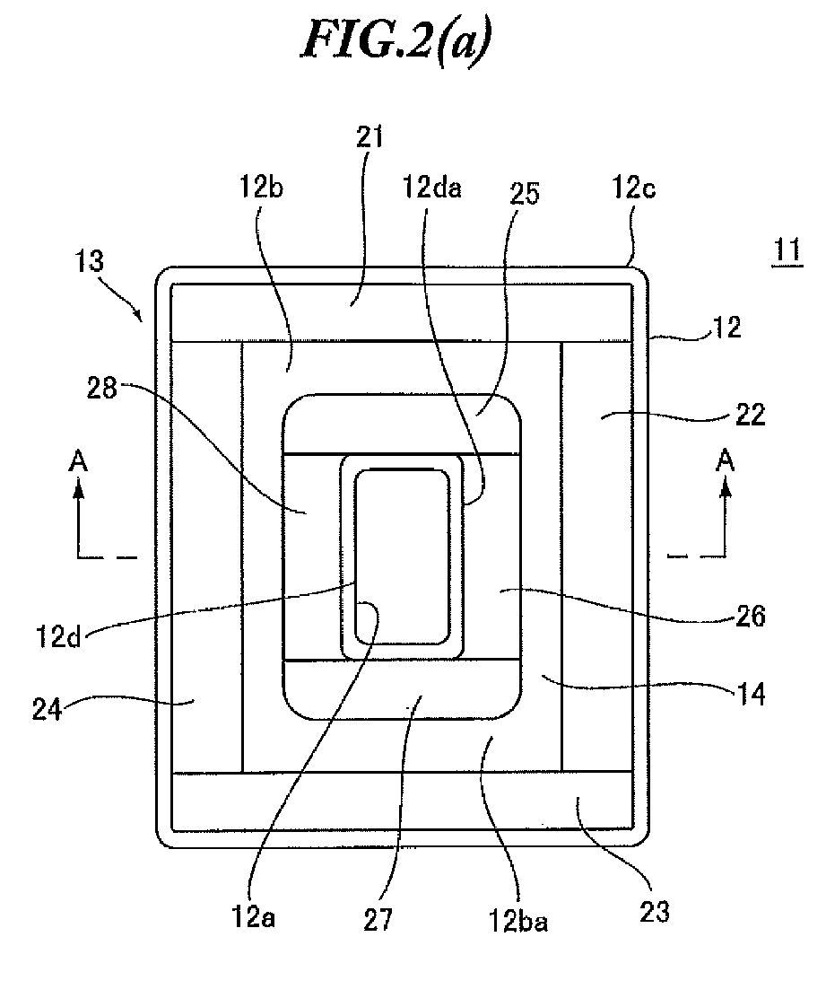
- Fig.2 is a schematic view showing the structure of a speaker magnetic circuit 11 according to embodiment 1 of the present invention, wherein Fig. 2(a) is a plan view and Fig. 2(b) is a sectional view taken along a line A-A in Fig. 2(a) .
- the speaker magnetic circuit 11 comprises a yoke 12 and a magnet group 13.
- the speaker magnetic circuit 11 is about 15mm inlongitudinal length, about 10mm intransverse length, and about 1.5mm in thickness.
- the yoke 12 is made of a pure iron, an oxygen-free steel, a silicon steel or the like.
- the whole shape of the yoke 12 is substantially rectangular in a plan view.
- a through-hole 12a having a substantially rectangular shape is formed at a substantially central portion of the yoke 12.
- the yoke 12 is formed by integrally including a bottom portion 12b, an outer circumferential side portion 12c, and an inner circumferential side portion 12d.
- the bottom potion 12b has a substantially square ring-shaped structure.
- the outer circumferential side portion 12c is set substantially upright on the outer edge of the bottom portion 12b, while the inner circumferential portion 12d is set substantially upright on the inner edge of the bottom portion 12b.
- the magnet group 13 comprises outer magnets 21-24 and inner magnets 25-28.
- the outer magnets 21-24 and the inner magnets 25-28 are made of a permanent magnet material such as Nd magnet, Sm-Co magnet, Al-Ni-Co magnet, ferrite magnet or the like.
- the outer magnets 21-24 and the inner magnets 26, 28 are each in a substantially prism shape.
- the magnets 25, 27 are fixed to the upper surface 12ba of the bottom portion 12b of the yoke 12, among eight corners of the inner magnets 25 and 27, four corners opposing the outer circumferential side portion 12c of the yoke 12 are rounded.
- the outer magnets 21-24 and the inner magnets 25-28 are each in a thickness substantially equal to a distance from the upper surface 12ba of the bottom portion 12b of the yoke 12 to the upper end of the outer circumferential side portion 12c.
- the outer magnets 21-24 are in contact not only with the upper surface 12ba of the bottom portion 12b and the inner surface 12ca of the outer circumferential side portion 12c of the yoke 12, but also with other adjacent outer magnets, and are fixed to the yoke 12 with an adhesive agent.
- the inner magnets 25-28 are in contact not only with the upper surface 12ba of the bottom portion 12b and the outer circumferential surface 12da of the inner circumferential side portion 12d of the yoke 12, but also with other adjacent inner magnets, and are fixed to the yoke 12 with an adhesive agent.
- a magnetic interval (magnetic gap) 14 is formed between the outer magnets 21-24 and the inner magnets 25-28.
- the outer magnets 21-24 and the inner magnets 25-28 are magnetized in an oblique direction with respect to their thickness direction.
- the outer magnets 21-24 as shown in Fig. 2(b) , have S pole on the front side (in sound emission direction) of the speaker device (see Fig.3 ) including the speaker magnetic circuit 11 and N pole on the rear side of the speaker device (opposite to sound emission direction), and are magnetized in a direction at an angle of about 10°-70° with respect to the horizontal direction facing outwardly from the center of the yoke 12.
- the outer magnets 21-24 are magnetized at an angle of about 10°- 70° as described above, a peak of the magnetic flux density can be disposed near a position where a voice coil described below is supported. Further, if the outer magnets 21-24 have S pole on the front side of the speaker device (in sound emission direction) and N pole on the rear side of the speaker device (opposite to sound emission direction), and are magnetized in a direction at an angle of about 30° - 45° with respect to the horizontal direction facing outwardly from the center of the yoke 12, it is possible to increase a magnetic flux density in the magnetic gap 14.
- the inner magnets 25-28 as shown in Fig.2 (b) , have S pole on the rear side of the speaker device (opposite to sound emission direction) and N pole on the front side of the speaker device (in sound emission direction) and are magnetized at an angle of about 10°-70° with respect to the horizontal direction facing outwardly from the center of the yoke 12. In this way, if the inner magnets 25-28 are magnetized at an angle of about 10°-70° as described above, the peak of magnetic flux density can be disposed near the position where the voice coil described below is supported.
- the inner magnets 25-28 have S pole on the rear side of the speaker device (opposite to sound emission direction) and N pole on the front side of the speaker device (in sound emission direction) and are magnetized at an angle of about 30°- 45° with respect to the horizontal direction facing outwardly from the center of the yoke 12, it is possible to increase the magnetic flux density in the magnetic gap 14.
- Fig.3 provides schematic sectional views showing the structure of a speaker device containing the speaker magnetic circuit shown in Fig.2 , wherein Fig. 3(a) shows an example in which the longitudinal cross-sectional shape of a diaphragm is generally conical (cone-shaped) and Fig. 3(b) shows an example in which the diaphragm is generally tabular.
- the speaker device has the speaker magnetic circuit 11 described above and a diaphragm assembly 31.
- the diaphragm assembly 31 comprises a diaphragm 32, a voice coil bobbin 33, a voice coil 34, and a frame (not shown).
- the diaphragm 32 has a generally rectangular shape in a plan view, its longitudinal cross sectional shape is generally conical (cone-shaped) (see Fig. 3(a) ) or generally tabular (see Fig.3 (b) ).
- a material forming the diaphragm 32 can be a paper, a cloth formed of a fiber, a woven fabric formed of a fiber, a non-woven fabric formed of a fiber, or a woven fabric impregnated with a phenol resin, a silicone resin or a solution containing such a resin and an organic solvent.
- the diaphragm 32 can also be formed of a metal material, a synthetic resin, or an acryl foamed material.
- the metal material can be aluminum, titanium, duralumin, beryllium, magnesium, or an alloy thereof.
- the synthetic resin can be a polypropylene, a polyethylene, a polystyrene, a polyethylene terephthalate, a polyethylene naphthalene, a polymethyl methacrylate, a polycarbonate, a polyarylate, an epoxy resin or the like.
- an acryl foamed material can be made by using a methyl methacrylate, a methacrylate, a styrene, an anhydrous maleic acid, and a methacrylamide as raw materials.
- a through-hole 32aa having a generally rectangular shape in a plan view is formed on the inner circumference 32a of the diaphragm 32 shown in Fig. 3(a) .
- the outer peripheral surface of the voice coil bobbin 33 having a generally square and tubular shape is fixed near its upper end to the through-hole 32aa with an adhesive agent.
- a voice coil 34 is wound around the outer peripheral surface of the voice coil bobbin 33 near the lower end thereof.
- a voice coil housing part 35 having a generally rectangular shape in a plan view is formed integrally with the diaphragm 32, in proximity of the inner circumference 32a of the diaphragm 32 shown in Fig. 3(b) .
- a voice coil 36 having a generally cylindrical shape is housed in the voice coil housing part 35, and is fixed therein with an adhesive agent.
- an edge portion 37 having a generally square and annular shape in a plan view is formed integrally with the voice coil housing part 35 and the diaphragm 32.
- Both ends of each of the voice coils 34 and 36 are led out respectively along the voice coil bobbin 33 or the diaphragm 32, and electrically connected to a pair of lead wires (not shown) near the inner circumference of the diaphragm 32.
- the pair of lead wires (not shown) are made of bending-resistant wires having a plurality of thin electric wires twisted.
- the audio current is supplied to the voice coil 34 or the voice coil 36 through the pair of lead wires (not shown).
- the outer magnets 21-24 and the inner magnets 25-28 are magnetized in an oblique direction with respect to their thickness direction. Therefore, the magnetic flux developed from the inner magnets 25-28 flows towards the outer magnets 21-24. Consequently, the magnetic fluxes can be efficiently collected at a position of the voice coil (described below) capable of ensuring the enough vibration amplitude for the voice coil 34 or the voice coil 36.
- the bottom surface and the side surface of the outer magnets 21-24 and the inner magnets 25-28 are in contact with the upper surface 12ba of the bottom portion 12b of the yoke 12, as well as with the inner surface 12ca of the outer circumferential side portion 12c or the outer surface 12da of the inner circumferential side portion 12d of the yoke 12, it becomes possible to reduce the magnetic flux leakage. Meanwhile, it will also be possible to increase the magnetic flux density in the magnetic gap 14 by increasing the contact area between the outer magnets 21-24 or the inner magnets 25-28 and the yoke 12 or increasing the sizes of the outer magnets 21-24 or the inner magnets 25-28.
- the magnetic flux density in the magnetic gap 14 will be greatly affected by the contact area between the outer magnets 21-24 or the inner magnets 25-28 and the yoke 12. If the outer magnets 21-24 and the inner magnets 25-28 are made of ferrite magnet, the magnetic flux density in the magnetic gap 14 will be greatly affected by the sizes of the outer magnets 21-24 and the inner magnets 25-28.
- Fig. 4 shows an example indicating a magnetic flux density distribution with respect to a distance from the upper surface 12ba of the bottom portion 12b of the yoke 12.
- curve a and b represent the characteristics of the speaker magnetic circuit 11 according to embodiment 1 of the present invention.
- Curve a represents the characteristic of the magnetic circuit when the magnetization direction of the outer magnets 21-24 and the inner magnets 25-28 is at about an angle of 60° with respect to the horizontal direction facing outwardly from the center of the yoke 12.
- Curve b represents the characteristic of the magnetic circuit when the magnetization direction of the outer magnets 21-24 and the inner magnets 25-28 is at an angle of about 30° with respect to the horizontal direction facing outwardly from the center of the yoke 12.
- curve c represents the characteristic of a conventional speaker magnetic circuit.
- BCP represents the position of voice coil. This position BCP of the voice coil represents a static position of the voice coil 34 when the speaker device is in its static state (the speaker device is not in its being-driven condition).
- the peak of the magnetic flux density distribution represented by curve a is closer to the center of the position BCP of voice coil.
- the peak of the magnetic flux density distribution represented by curve b is higher than that represented by curve c .
- an example which involves the provision of both the outer magnets 21-24 and the inner magnets 25-28.
- the present invention should not be limited to this example.
- a magnetic interval (magnetic gap) 42 is formed between the outer side face of the inner magnets 25-28 and the inner surface of the outer circumferential portion 12c of the yoke 12.
- a magnetic interval (magnetic gap 44) is formed between the inner side surface of the outer magnets 21-24 and the outer surface of the inner circumferential side portion 12d of the yoke 12.
- the parts corresponding to those shown in Fig. 2 (b) are labeled with the same reference numerals as those shown in Fig.2 (b) , with the explanations thereof omitted.
- the speaker device including the speaker magnetic circuit 41 or 43 can prevent a decrease of magnetic flux density in the magnetic gap 42 or 44, it is possible to ensure a great magnetic flux density in the magnetic gap 42 or 44. Furthermore, it is also possible to reduce the number of parts involved.
- embodiment 1 there is shown an example in which the bottom surfaces and side faces of the outer magnets 21-24 and the inner magnets 25-28 are in contact with the upper surface 12ba of the bottom portion 12b of the yoke 12, the inner surface 12ca of the outer circumferential side portion 12c, or the outer surface 12da of the inner circumferential side portion 12d.
- the above-discussed embodiment 1 also shows an example in which the outer magnets 21-24 and the inner magnets 25-28 are in a thickness substantially equal to a distance from the upper surface 12ba of the bottom portion 12b of the yoke 12 to the upper end of outer circumferential side portion 12c.
- the present invention is not limited to these examples.
- intervals are provided between the upper surface 12ba of the bottom portion 12b of the yoke 12 and the outer magnets 21-24 as well as the inner magnets 25-28, while the side faces of the outer magnets 21-24 and the inner magnets 25-28 are attached to the outer circumferential side portion 12c and the inner circumferential side portion 12d of the yoke 12.
- the parts corresponding to those shown in Fig.2 are labeled with the same reference numerals as those shown in Fig.2 , with the descriptions thereof omitted.
- FIG.7 there are outer magnets 46 and 47 corresponding to the outer magnets 22 and 24 shown in Fig. 2(a) and Fig. 2(b) but thinner than the outer magnets 22 and 24, such as having a thickness which is substantially half of the thickness of the outer magnets 22 and 24.
- Fig.7 does not show two other outer magnets corresponding to the outer magnets 21 and 23 shown in Fig.
- Fig. 7 does not show two other inner magnets corresponding to the inner magnets 25 and 27 shown in Fig. 2(a) but thinner than the inner magnets 25 and 27, such as having a thickness which is substantially half of the thickness of the inner magnets 25 and 27.
- outer magnets 46, 47 and the two other outer magnets are in contact with the inner surface 12ca of the outer circumferential side portion 12c of the yoke 12, as well as with other adjacent outer magnets, and are fixed to the yoke 12 with an adhesive agent.
- inner magnets 48, 49 and the two other inner magnets are in contact with the outer surface12da of the inner circumferential side portion 12d of the yoke 12, as well as with other adjacent inner magnets, and are fixed to the yoke 12 with an adhesive agent.
- a magnetic interval (magnetic gap) 50 is formed between the outer surfaces of the inner magnets 48, 49 as well as the two other inner magnets (not shown) and the inner surfaces of the outer magnets 46, 47 as well as the two other outer magnets (not shown).
- the outer magnets 46, 47 and the two other outer magnets have S pole on the front side of the speaker device including the speaker magnetic circuit 45 (in sound emission direction) and N pole on the rear side of the speaker device (opposite to sound emission direction), and are magnetized in a direction at an angle of about 10°-70° with respect to the horizontal direction to facing outwardly from the center of the yoke 12. In this way, if the outer magnets 46, 47 and the two other outer magnets (not shown) are magnetized at an angle of about 10°- 70° as described above, a peak of the magnetic flux density can be ensured near a position where a voice coil is supported.
- outer magnets 46, 47 and the two other outer magnets have S pole on the front side of the speaker device (in sound emission direction) and N pole on the rear side of the speaker device (opposite to sound emission direction), and are magnetized in a direction at an angle of about 30° - 45° with respect to the horizontal direction e facing outwardly from the center of the yoke 12, it is possible to increase a magnetic flux density in the magnetic gap 50.
- the inner magnets 48, 49 and the two other inner magnets have S pole on the rear side of the speaker device (opposite to sound emission direction) and N pole on the front side of the speaker device (in sound emission direction) and are magnetized at an angle of about 10°-70° with respect to the horizontal direction facing outwardly from the center of the yoke 12.
- the inner magnets 48, 49 and the two other inner magnets are magnetized at an angle of about 10°-70° as described above, the peak of magnetic flux density can be ensured near the position where the voice coil described below is supported.
- the inner magnets 48, 49 and the two other inner magnets have S pole on the rear side of the speaker device (opposite to sound emission direction) and N pole on the front side of the speaker device (in sound emission direction) and are magnetized at an angle of about 30°- 45° with respect to the horizontal direction facing outwardly from the center of the yoke 12, it is possible to increase the magnetic flux density in the magnetic gap 14.
- the yoke 12 is obtained by integrally forming the bottom portion 12b, the outer circumferential side portion 12c, and the inner circumferential side portion 12d.
- the present invention should not be limited to this example.
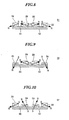
- Fig.8 parts corresponding to those shown in Fig.2 are labeled with the same reference numerals as those shown in Fig.2 , with the description thereof omitted.
- the yoke 52 can be made of a pure iron, an oxygen-free steel, a silicon steel or the like.
- the above-described outer magnets 22, 24 and the two outer magnets 21, 23 are in contact with the upper surface of the outer circumference of the yoke 52, and are fixed to the yoke 52 with an adhesive agent.
- the inner magnets 26, 28 are provided at a certain interval in a generally central position of the upper surface of the yoke 52.
- the two inner magnets 25, 27 are arranged such that their upper and lower ends of the same side surfaces are in contact with the end faces of the inner magnets 26, 28, and are fixed to the yoke 52 by applying an adhesive agent to the contacting portions.
- a magnetic gap 14 is formed between the outer circumferential surfaces of the inner magnets 26, 28 as well as the two other inner magnets 25, 27 (not shown) and the inner circumferential surfaces of the outer magnets 22, 24 as well as the two other outer magnets 21, 23 (not shown).
- Using the speaker device including the speaker magnetic circuit 51 can prevent a decrease of the magnetic flux density in the magnetic gap 14, thereby ensuring a high magnetic flux density in the magnetic gap 14.
- Fig.9 is a schematic sectional view showing the structure of a speaker magnetic circuit 53 according to embodiment 5 of the present invention.
- parts corresponding to those shown in Fig.8 are labeled with the same reference numerals as those shown in Fig. 8 , with the description thereof omitted.
- the outer magnets 22, 24 shown in Fig.8 and two other outer magnets 21, 23 have been replaced with outer magnets 54, 55 and two other outer magnets (not shown).
- outer magnets 54, 55 and the two other outer magnets are made of a material similar to the outer magnets 21-24, they are thinner than the inner magnets 26 and 28, having a thickness which is substantially a half of the thickness of the inner magnets 26 and 28.
- Fig. 9 shows the outer magnets 54, 55 and the inner magnets 26, 28, the figure does not show the two other outer magnets corresponding to the outer magnets 21, 23 in Fig.2(a) and having a smaller thickness than the outer magnets 21, 23 (for example, half the thickness of the outer magnets 21, 23).
- Fig. 9 does not show the inner magnets 25 and 27 shown in Fig. 2(a) , either.
- the outer magnets 54 and 55 described above and two other outer magnets (not shown) are in contact with the upper surface of the outer circumference of the yoke 52, as well as with other adjacent outer magnets, and are fixed to the yoke 52 with an adhesive agent.
- the inner magnets 26 and 28 are provided at a certain interval from each other in a generally central portion of the yoke 52, while two other inner magnets (not shown) are arranged in such a condition that the upper and lower ends on the same side surface are in contact with the end surfaces of the inner magnets 26 and 28, and are fixed to the yoke 52 by applying an adhesive agent to the contacting portions.
- a magnetic gap 56 is formed between the outer circumferential surfaces of the inner magnets 26, 28 and the two other inner magnets (not shown) on one hand and the inner circumferential surfaces of the outer magnets 54, 55 and two other outer magnets (not shown) on the other.
- the outer magnets 54, 55 and the two other outer magnets have S pole on the front side of the speaker device including the speaker magnetic circuit 53 (in sound emission direction) and N pole on the rear side of the speaker device (opposite to sound emission direction), and are magnetized in a direction at an angle of about 10°-70° with respect to the horizontal direction facing outwardly from the center of the yoke 52.
- the outer magnets 54, 55 and the two other outer magnets are magnetized at an angle of about 10°- 70° as described above, a peak of the magnetic flux density can be ensured near a position where a voice coil is supported.
- the outer magnets 54, 55 and the two other outer magnets have S pole on the front side of the speaker device (in sound emission direction) and N pole on the rear side of the speaker device (opposite to sound emission direction), and are magnetized in a direction at an angle of about 30° - 45° with respect to the horizontal direction facing outwardly from the center of the yoke 52, it is possible to increase a magnetic flux density in the magnetic gap 56.
- the magnetization direction of the inner magnets 25-28 is different from the magnetization direction of the outer magnets 54, 55 and two other outer magnets (not shown), it is possible to ensure the peak of the magnetic flux density near the position where the voice coil is supported.
- the speaker device including the speaker magnetic circuit 52 can prevent a decrease of magnetic flux density in the magnetic gap 56, thereby ensuring a great magnetic flux density in the magnetic gap 56.
- Fig.10 is a schematic sectional view showing the structure of the speaker magnetic circuit 57 according to embodiment 6 of the present invention.
- the parts corresponding to those shown in Fig.8 are labeled with the same reference numerals as those shown in Fig.8 , with the description thereof omitted.
- the inner magnets 26, 28 and the two other inner magnets 25, 27 have been replaced with inner magnets 58, 59 and two other inner magnets (not shown).
- the inner magnets 58, 59 and the two other outer magnets are made of a material similar to the inner magnets 25-28, they are thinner than the outer magnets 22 and 24, having a thickness which is approximately half of the thickness of the magnets 22 and 24.
- Fig. 10 shows the inner magnets 58, 59 and the outer magnets 22, 24, but does not show the two inner magnets corresponding to the inner magnets 25, 27 shown in Fig. 2(a) and thinner than the inner magnets 25 and 27 (having a thickness which is half of the thickness of the inner magnets 25 and 27).
- Fig. 10 does not show the outer magnets 21, 23 shown in Fig. 2(a) .
- the inner magnets 58, 59 and the two other inner magnets are provided in a generally central position of the upper surface of the yoke 52, with the inner magnets 58, 59 separated at a predetermined interval. Meanwhile, the two inner magnets (not shown) are arranged in a condition such that the upper and lower ends on the same side surface are in contact with the end faces of the inner magnets 58 and 59, and are fixed to the yoke 52 by applying an adhesive agent to the contacting portions.
- the outer magnets 22, 24 and the two other outer magnets 21 and 23 are in contact with the upper surface of the outer circumference of the yoke 52, as well as with other adjacent inner magnets, and are fixed to the yoke 52 with an adhesive agent.
- a magnetic gap 60 is formed between the outer circumferential surfaces of the inner magnets 58, 59 and the two other inner magnets (not shown) on one hand and the inner circumferential surfaces of the outer magnets 22, 24 and the two other outer magnets 21, 23(not shown) on the other.
- the inner magnets 58, 59 and the two other inner magnets have S pole on the rear side of the speaker device including the speaker magnetic circuit 57 (opposite to sound emission direction) and N pole on the front side of the speaker device (in sound emission direction), and are magnetized in a direction at an angle of about 10°-70° with respect to the horizontal direction facing outwardly from the center of the yoke 52.
- the inner magnets 58, 59 and the two other inner magnets (not shown) are magnetized at an angle of about 10°- 70° as described above, a peak of the magnetic flux density can be ensured near a position where a voice coil is supported.
- the inner magnets 58, 59 and the two other inner magnets have S pole on the rear side of the speaker device (opposite to sound emission direction) and N pole on the front side of the speaker device (in sound emission direction), and are magnetized in a direction at an angle of about 30° - 45° with respect to the horizontal direction facing outwardly from the center of the yoke 52, it is possible to increase a magnetic flux density in the magnetic gap 60.
- the magnetization direction of the outer magnets 21-24 is different from the magnetization direction of the inner magnets 58, 59 and two other inner magnets (not shown), it is possible to ensure the peak of the magnetic flux density near the position where the voice coil is supported.
- the speaker device including the speaker magnetic circuit 57 can prevent a decrease of magnetic flux density in the magnetic gap 60, thereby ensuring a great magnetic flux density in the magnetic gap 60.
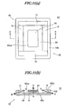
- Fig.11 is a schematic view showing the structure of a speaker magnetic circuit 61 according to embodiment 7 of the present invention, wherein Fig. 11 (a) is a plan view and Fig. 11 (b) is a sectional view taken along A-A line of Fig.11(a) .
- the speaker magnetic circuit 61 of embodiment 7 has a yoke 62, a magnet group 63, and a plate 64.
- the yoke 62 can be made of, for example, a pure iron, an oxygen-free steel, a silicon steel or the like.
- the whole shape of the yoke 62 is generally rectangular and tabular in a plan view.
- the yoke 62 can be structured such that the bottom portion 62a and the outer circumferential edge portion 62b are formed separately or integrally. In the example shown in Fig.11 , the bottom portion 62a and the outer circumferential edge portion 62b are formed separately.
- the shape of the bottom portion 62a is generally rectangular and tabular in a plan view.
- the outer circumferential edge portion 62b has a generally square and ring-shape in a plan view.
- the outer circumferential edge portion 62b is in contact with the outer circumference of the bottom portion 62a and is fixed to the bottom portion 62a with an adhesive agent.
- the magnet group 63 comprises outer magnets 71-74 and inner magnet 75.
- the outer magnets 71-74 and the inner magnet 75 can be made of a permanent magnet material such as Nd magnet, Sm-Co magnet, Al-Ni-Co magnet, ferrite magnet or the like.
- the outer magnets 71-74 are in a generally prism shape.
- the shape of the inner magnet 75 is generally rectangular and planar in a plan view.
- the outer magnets 71-74 are in a thickness substantially equal to a distance from the upper surface 62aa of the bottom portion 62a of the yoke 62 to the upper end of the outer circumferential edge portion 62b.
- the inner magnet 75 is in a thickness smaller than the thickness of the outer magnets 71-74, such as a half of a distance from the upper surface 62aa of the bottom portion 62a of the yoke 62 to the upper end of the outer circumferential edge portion 62b.
- the outer magnets 71-74 are in contact not only with the upper surface 62aa of the bottom portion 62a and the inner circumferential surface 62ba of the outer circumferential edge portion 62c of the yoke 62, but also with other adjacent outer magnets, and are fixed to the yoke 62 with an adhesive agent.
- the inner magnet 75 is fixed to a generally central position of the upper surface 62aa of the bottom portion 62a of the yoke 62 with an adhesive agent.
- the plate 64 is fixed on upper surface of the inner magnet 75 with an adhesive agent.
- the shape of the plate 64 is generally rectangular and tabular in a plan view, having a size substantially the same as the inner magnet 74.
- the plate 64 can be made of, for example, a soft magnetic material (e. g. , a low carbon steel).
- a magnetic interval (magnetic gap) 65 is formed between the outer magnets 71-74 and the inner magnet 75.
- the outer magnets 71-74 are magnetized in an oblique direction with respect to their thickness direction.
- the outer magnets 71-74 as shown in Fig. 11(b) , have S pole on the front side of the speaker device including the speaker magnetic circuit 61 (in sound emission direction) and N pole on the rear side of the speaker device (opposite to sound emission direction), and are magnetized in a direction at an angle of about 10°-70° with respect to the horizontal direction facing outwardly from the center of the yoke 62.
- the outer magnets 71-74 are magnetized at an angle of about 10°- 70° as described above, a peak of the magnetic flux density can be ensured near a position where a voice coil described below is supported. Further, if the outer magnets 71-74 have S pole on the front side of the speaker device (in sound emission direction) and N pole on the rear side of the speaker device (opposite to sound emission direction), and are magnetized in a direction at an angle of about 30° - 45° with respect to the horizontal direction facing outwardly from the center of the yoke 62, it is possible to increase a magnetic flux density in the magnetic gap 65.
- the inner magnet 75 as shown in Fig.2(b) , has S pole on the rear side of the speaker device (opposite to sound emission direction) and N pole on the front side of the speaker device (in sound emission direction) and is magnetized in a direction generally parallel to the vertical direction (thickness direction of the inner magnet 75).
- the speaker device containing the speaker magnetic circuit 61 it is possible to prevent a decrease of the magnetic flux density within the magnetic gap 65, making it possible to ensure a great magnetic flux density in the magnetic gap 65. Further, if the magnetization direction of the outer magnets 71-74 is different from the magnetization direction of the inner magnet 75, it is possible to ensure a peak of the magnetic flux density near the position where the voice coil is supported.
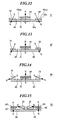
- Fig. 12 is a schematic sectional view showing the structure of a speaker magnetic circuit 81 according to embodiment 8 of the present invention.
- the parts corresponding to those shown in Fig.11 are labeled with the same reference numerals as those shown in Fig.11 , with the description thereof omitted.
- the outer circumferential side portion 62b and the outer magnets 71-74 shown in Fig. 11 have been replaced with outer circumferential side portion 62c, outer magnets 82, 83, and two other outer magnets (not shown).
- the outer circumferential side portion 62c is made of a material similar to the outer circumferential side portion 62b, having a thickness substantially equal to the thickness of the inner magnet 75.
- Fig.12 shows the inner magnet 75 and the outer magnets 82, 83, but does not show two other outer magnets corresponding to the outer magnets 71, 74 in Fig.11 and having a thickness substantially equal to the thickness of the inner magnet 75.
- the outer circumferential side portion 62c has a generally square and ring-shape in a plan view.
- the outer circumferential side portion 62c is in contact with the outer circumference of the bottom portion 62a, and is fixed to the bottom portion 62a with an adhesive agent.
- the outer magnets 82, 83 and the two other outer magnets are in contact with the upper surface 62aa of the bottom portion 62a and the inner circumferential surface 62ca of the outer circumferential side portion 62c, as well as with adjacent other outer magnets, and are fixed to the bottom portion 62a and the outer circumferential side portion 62c with an adhesive agent.
- a magnetic interval (magnetic gap) 84 is formed between the outer magnets 82, 83 and the two other outer magnets (not shown) on one hand and the inner magnet 75 on the other.
- the outer magnets 82, 83 and two other outer magnets (not shown) are magnetized in an oblique direction with respect to their thickness direction.
- the outer magnets 82, 83 and two other outer magnets have S pole on the front side of the speaker device including the speaker magnetic circuit 81 (in sound emission direction) and N pole on the rear side of the speaker device (opposite to sound emission direction), and are magnetized at an angle of about 10°- 70° with respect to the horizontal direction e facing outwardly from the center of the bottom portion 62a.
- the outer magnets 82, 83 and the two other outer magnets (not shown) are magnetized at an angle of about 10°-70° as described above, the peak of the magnetic flux density can be ensured near the position where the voice coil is supported.
- the outer magnets 82, 83 and two other outer magnets have S pole on the front side of the speaker device (in sound emission direction) and N pole on the rear side of the speaker device (opposite to sound emission direction) and are magnetized at an angle of about 30°- 45° with respect to the horizontal direction facing outwardly from the center of the bottom portion 62a, it is possible to increase the magnetic flux density in the magnetic gap 84.
- the speaker device including the speaker magnetic circuit 81, it is possible to prevent a decrease of the magnetic flux density within the magnetic gap 84, making it possible to ensure a e great magnetic flux density in the magnetic gap 84. Further, if the magnetization direction of the outer magnets 82, 83 and the two other outer magnets (not shown) is different from the magnetization direction of the inner magnet 75, it is possible to ensure a peak of the magnetic flux density near the position where the voice coil is supported.
- Fig.13 is a schematic sectional view showing the structure of the speaker magnetic circuit 85 according to embodiment 9 of the present invention.
- the parts corresponding to those shown in Fig.11 are labeled with the same reference numerals as those shown in Fig.11 , with the description thereof omitted.
- the yoke 62 shown in Fig.11 has been replaced with a yoke 86.
- the yoke 86 is made of a material similar to the bottom portion 62a, and has a generally rectangular tabular shape in a plan view. like the bottom 62a.
- the area of the yoke 86 is smaller than that of the bottom portion 62a by an area substantially equal to the bottom area of the outer circumferential side portion 62b (here, it has been removed).
- Fig.13 shows the inner magnet 75, the outer magnets 82, 83 and the plate 64, but does not show the outer magnets corresponding to the outer magnets 71, 74 in Fig.11 and having a thickness substantially equal to the thickness of the inner magnet 75.
- the outer magnets 82, 83 described above and the two other outer magnets (not shown) are in contact with the upper surface 62aa of the bottom portion 62a, as well as with adjacent other outer magnets, and are fixed to the yoke 86 with an adhesive agent.
- the inner magnet 75 is fixed to a substantially central position of the upper surface of the yoke 86.
- a magnetic interval (magnetic gap) 87 is formed between the outer magnets 82, 83 and the two other outer magnets (not shown) on one hand and the inner magnet 75 on the other.
- the speaker device including the speaker magnetic circuit 85, it is possible to prevent a decrease of the magnetic flux density within the magnetic gap 87, making it possible to ensure a great magnetic flux density in the magnetic gap 87. Further, if the magnetization direction of the outer magnets 72, 74 and the two other outer magnets (not shown) is different from the magnetization direction of the inner magnet 75, it is possible to ensure a peak of the magnetic flux density near the position where the voice coil is supported.
- Fig.14 is a schematic sectional view showing the structure of the speaker magnetic circuit 88 according to embodiment 10 of the present invention.
- parts corresponding to those shown in Fig.11 are labeled with the same reference numerals as those shown in Fig.11 , with the description thereof omitted.
- the yoke 62 shown in Fig.11 is replaced with the yoke 86 shown in Fig.13 .
- the structure of the speaker magnetic circuit 88 according to embodiment 10 is similar to the speaker magnetic circuit 61 according to embodiment 7, except the outer circumferential side portion 62b removed.
- a magnetic interval (magnetic gap) 65 is formed between the outer magnets 72, 74 and two other outer magnets71, 73 (not shown) on one hand and the inner magnet 75 on the other.
- the speaker device including the speaker magnetic circuit 88, it is possible to prevent a decrease of the magnetic flux density within the magnetic gap 65, making it possible to ensure a e great magnetic flux density in the magnetic gap 65. Further, if the magnetization direction of the outer magnets 72, 74 and the two other outer magnets (not shown) is different from the magnetization direction of the inner magnet 75, it is possible to ensure a peak of the magnetic flux density near the position where the voice coil is supported.
- Fig.15 is a schematic sectional view showing the structure of the speaker magnetic circuit 91 according to embodiment 11 of the present invention.
- parts corresponding to those shown in Fig.9 are labeled with the same reference numerals as those shown in Fig. 9 , with the description thereof omitted.
- the outer magnets 54, 55 shown in Fig.9 and two other outer magnets (not shown) isreplaced with outer magnets 92, 93 and two other outer magnets (not shown).
- plates 94, 95 and two plates (not shown) are fixed respectively on the upper surfaces of the outer magnets 92, 93 and the two other outer magnets (not shown) with an adhesive agent.
- the plates 94, 95 and the two plates (not shown) are wider than the corresponding outer magnets 92, 93 and the two outer magnets.
- the outer magnets 92, 93 and the two outer magnets (not shown), as shown in Fig.15 for example, have S pole on the front side of the speaker device including the speaker magnetic circuit 91 (in sound emission direction) and N pole on the rear side of the speaker device (opposite to sound emission direction), and are magnetized in a direction generally parallel to the vertical direction.
- a magnetic interval (magnetic gap) 96 is formed between the outer magnets 92, 93 and the two outer magnets (not shown) on one hand and the inner magnets 26, 28 on the other.
- the speaker device including the speaker magnetic circuit 91 it is possible to prevent a decrease of the magnetic flux density within the magnetic gap 96, making it possible to ensure a great magnetic flux density in the magnetic gap 96. Further, if the magnetization direction of the outer magnets 92, 93 and the two other outer magnets (not shown) is different from the magnetization direction of the inner magnets 26, 28 and the two other inner magnets (not shown), it is possible to ensure a peak of the magnetic flux density near the position where the voice coil is supported. In this way, even if a speaker device including a speaker magnetic circuit 91 is thin and compact in size, it is possible to ensure a great magnetic flux density.
- the whole shape of the speaker magnetic circuit is generally rectangular in a plan view.
- the present invention should not be limited by this.
- the whole shape of the speaker magnetic circuit to be generally circular, elliptical, or polygonal in a plan view.
- the outer magnets and the inner magnets provided on upper surface of the yoke are each composed of a plurality of magnets.
- the present invention should not be limited by this.
- each or both of the outer magnets and the inner magnets to be formed of single one annular magnet.
- description is given to explain an example in which an whole shape of the speaker magnetic circuit is generally circular in a plan view and the outer magnet and the inner magnet arranged on upper surface of the yoke are each formed of one annular magnet.
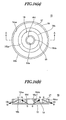
- Fig.16 is a schematic view showing the structure of a speaker magnetic circuit 15 according to embodiment 12 of the present invention, wherein Fig. 16 (a) is a plan view and Fig. 16(b) is a sectional view taken along A-A line in Fig.16 (a) .
- the speaker magnetic circuit 15 according to embodiment 12 comprises a yoke 16, an outer magnet 17, and an inner magnet 18.
- the speaker magnetic circuit 15 has, for example, an outer diameter of about 10mm and a thickness of about 1.5mm.
- the yoke 16 is made of, for example, a pure iron, an oxygen-free steel, a silicon steel or the like.
- the whole shape of the yoke 16 is generally circular in a plan view.
- a through-hole 16a having a generally circular shape.
- Yoke 16 includes a bottom portion 16b, an outer circumferential side portion 16c, and an inner circumferential side portion 16d, which are formed integrally to form the yoke.
- the bottom portion 16b is generally annular in shape.
- the outer circumferential side portion 16c is arranged generally upright on the outer circumference of the bottom portion 16b.
- the inner circumferential side portion 16d is arranged generally upright on the inner circumference of the bottom portion 16b.
- the outer magnet 17 and the inner magnet 18 are made of a permanent magnet material such as Nd magnet, Sm-Co magnet, Al-Ni-Co magnet, ferrite magnet or the like.
- the outer magnet 17 and the inner magnet 18 are each in a generally annular shape.
- the outer magnet 17 and the inner magnet 18 are each in a thickness substantially equal to a distance from the upper surface 16ba of the bottom portion 16b of the yoke 16 to the upper end of the outer circumferential side portion 16c.
- the outer magnet 17 is in contact with the upper surface 16ba of the bottom portion 16b and the inner circumferential surface 16ca of the outer circumferential side portion 16c of the yoke 16, and is fixed to the yoke 16 with an adhesive agent.
- the inner magnet 18 is in contact with the upper surface 16ba of the bottom portion 16b and the outer circumferential surface 16da of the inner circumferential side portion 16d of the yoke 16, and is fixed to the yoke 16 with an adhesive agent.
- a magnetic interval (magnetic gap) 19 is formed between the outer magnet 17 and the inner magnet 18.
- the outer magnet 17 and the inner magnet 18 are magnetized in an oblique direction with respect to their thickness direction.
- the outer magnet 17, as shown in Fig.16 (b) has S pole on the front side of the speaker device (not shown) including the speaker magnetic circuit 15 (in sound emission direction) and N pole on the rear side of the speaker device (opposite to sound emission direction), and is magnetized at an angle of about 10°-70° with respect to the horizontal direction facing outwardly from the center of the yoke 16.
- the outer magnet 17 is magnetized at an angle of about 10°-70° as described above, the peak of magnetic flux density can be ensured near the position where the voice coil is supported.
- the outer magnet 17 has S pole on the front side of the speaker device (in sound emission direction) and N pole on the rear side of the speaker device (opposite to sound emission direction), and is magnetized at an angle of about 30°- 45° with respect to the horizontal direction facing outwardly from the center of the yoke 16, it is possible to increase the magnetic flux density in the magnetic gap 19.
- the inner magnet 18, as shown in Fig.2(b) for example has S pole on the rear side of the speaker device (opposite to sound emission direction) and N pole on the front side of the speaker device (in sound emission direction) and is magnetized at an angle of about 10°-70° with respect to the horizontal direction facing outwardly from the center of the yoke 16.
- the inner magnet 18 is magnetized at an angle of about 10°-70° as described above, the peak of the magnetic flux density can be ensured near the position where the voice coil is supported.
- the inner magnet 18 has S pole on the rear side of the speaker device (opposite to sound emission direction) and N pole on the front side of the speaker device (in sound emission direction) and is magnetized at an angle of about 30°- 45° with respect to the horizontal direction facing outwardly from the center of the yoke 16, it is possible to increase the magnetic flux density within the magnetic gap 19.
- Step 1 magnet formation step
- a container 101 as shown in Fig.17 is fully filled with an amount of magnetic powder (magnetic fluid) 102.
- a magnetic field is applied in an oblique and upward direction with respect to the vertical direction (oblique with respect to the thickness direction of a magnet 103 described below) from the bottom 101a of the container 101, as represented by an arrow in Fig. 17 .
- a pressure is applied to the magnetic powder (magnetic fluid) to form a magnet (solid) 103.
- the pressure should be applied in a direction generally perpendicular to the magnetic field direction, so as to maximize the magnetic performance of the magnet 103.
- the orientation of the magnetic powder (magnetic material) 102 can be determined through the magnet formation step described above.
- the magnet 103 obtained in the above Step 1 is fixed along the outer circumference of the upper surface of the yoke 86 using an adhesive agent, thereby producing a yoke assembly.
- Step 3 magnet magnetizing step
- the magnetizing apparatus 111 comprises a magnetizing yoke 112 and a magnetizing coil 113.
- the yoke assembly obtained in the above Step 2 is set in the magnetizing apparatus 111.
- a magnetic field is applied in a direction substantially parallel to a direction of a magnetic orientation of the magnet 103, so as to magnetize the magnet 103, thereby obtaining the outer magnets 71-74.
- a plate 64 is fixed on a magnet being as an inner magnet 75, thereby producing a plate assembly.
- the plate assembly obtained in the above Step 4 is set in the magnetizing apparatus. Then, as shown in Fig.14 , a magnetic field is applied in a direction substantially parallel to the thickness direction of the above plate assembly, thereby magnetizing the magnet of the plate assembly, thus obtaining the inner magnet 75.
- the assembly obtained in the above Step 5 is fixed with an adhesive agent or a jig to a generally central position of the yoke 86 in the assembly obtained in the above Step 3, thereby obtaining the speaker magnetic circuit 88 shown in Fig.14 .
- Fig.19 is a schematic sectional view showing the structure of the speaker device according to embodiment 14 of the present invention.
- the speaker device comprises a speaker magnetic circuit 88 according to embodiment 10 of the present invention as shown in Fig.14 , a frame 121, a diaphragm 122, and a voice coil 123.
- the frame 121 can be made of a ferrous metal, a non-ferrous metal or their alloy, or a synthetic resin.
- a ferrous metal can be a pure iron, an oxygen-free steel, a silicon steel or the like.
- a non-ferrous metal can be aluminum, magnesium, zinc or the like.
- a synthetic resin can be produced by adding a glass-fiber or a fibrillated thermotropic liquid crystal polyester resin as a reinforcing filler in a thermoplastic resin such as an olefin resin including a polypropylene or the like, an ABS (acrylonitrile butadiene styrene), or a polyethylene terephthalate.
- the frame 121 can be produced, for example, by squeezing and forming a ferrous metal, or molding and forming non-ferrous metals or their alloy, or injection molding a synthetic resin.
- An whole shape of the frame 121 is generally rectangular in a plan view. Specifically, the frame 121 has a stepped engaging portion 121a formed at the upper end on the side of an inner circumference for engaging with an end of the yoke 86, and a stepped engaging portion 121b formed at the upper end on the side of an outer circumference for engaging with an end of the diaphragm 122.
- the diaphragm 122 comprises a dome-shaped vibrating part 131, a voice coil bobbin 132, a conical vibrating part 133, and an edge 134.
- the dome-shaped vibrating part 131, the voice coil bobbin 132, the conical vibrating part 133, and the edge 134 are formed integrally together.
- the diaphragm 122 can be made of, for example, a paper, a cloth formed of a fiber, a woven fabric, a non-woven fabric, , all impregnated with a phenol resin, a silicone resin or a solution containing the resins and an organic solvent.
- the diaphragm 122 can also be made of a metal material, a synthetic resin, a propylene foamed material or the like.
- the metal material can be, for example, aluminum, titanium, duralumin, beryllium, magnesium, or their alloy.
- the synthetic resin can be, for example, a polypropylene, a polyethylene, a polystyrene, a polyethylene terephthalate, a polyethylene naphthalate, a polymethyl methacrylate, a polycarbonate, a polyarylate, an epoxy resin or the like.
- the acrylic foamed material can be made from, as a raw material, a methylmethacrylate, a methacrylate, a styrene, an anhydrous maleic acid, or an methacrylamide.
- the dome-shaped vibrating part 131 has a shape protruding in the center of the diaphragm 122 on the front side of the speaker device (in sound emission direction).
- the dome-shaped vibrating part 131 has a longitudinal section formed in a radially curved shape, a semispherical domed shape, a conical shape, a multi-stepped curved shape or the like.
- the dome-shaped vibrating part 131 is so formed that its longitudinal section is in a radially curved shape and its central top is higher than the edge 134. With such configuration, it is possible to obtain a broad-angled directional characteristic.
- the dome-shaped vibrating part 131 can be supported in a predetermined position on the plate 64 with the voice coil bobbin 132, the conical vibrating part 133 and the edge 134, vibratably in the driving direction.
- the voice coil bobbin 132 is formed between the dome-shaped vibrating part 131 and the edge 134, and has a generally L-shaped cross-section in the example shown in Fig.18 .
- a voice coil 123 formed into an substantially square and tubular shape, falls into a concave part formed between the voice coil bobbin 132 and the conical vibrating part 133, and is fixed with an adhesive agent such as an epoxy resin or the like.
- the conical vibrating part 133 is formed from the lower end of the voice coil bobbin 132 to the edge 134 of the diaphragm 122. Further, the conical vibrating part 133 has a cross section whose generatrix is generally conical. In addition, the conical vibrating part 133 can be formed such that its cross section has a generatrix in a shape which is an arc-curved cone, a flat cone formed in a shape of a straight line, a parabolic cone or the like.
- the diaphragm 122 having the above-described structure vibratably supports the voice coil 123 near the end of the plate 64, .
- the diaphragm 122 in the concave part located between the voice coil bobbin 132 and the conical vibrating part 133 is formed widely extending from the bottom of the concave part to an upper opening side thereof, thereby the diaphragm 122 is formed easily.
- the edge 134 has an engaging portion 134a for engaging with the stepped portion 121b of the frame 121. Therefore, it is possible to perform a positioning of the diaphragm 122 with respect to the speaker magnetic circuit 88 and the frame 121 by performing an engagement between the stepped portion 121b of the frame 121 and the engaging portion 134a of the edge 134.
- the voice coil 123 is supported by the diaphragm 122 at a specified position within a magnetic flux distribution formed with the outer magnets 71-74, the inner magnet 75, the plate 64, and the yoke 86.
- the audio current is supplied through a pair of lead wires (not shown) to the voice coil 123.
- the outer magnets 71-74 are magnetized in an oblique direction with respect to their thickness direction, while the inner magnet 75 is magnetized in a direction generally parallel to its thickness direction. Therefore, the magnetic flux generated from the inner magnet 75 flows towards the outer magnets 71-74. As a result, the magnetic flux is collected efficiently at or near the voice coil position where the adequate vibration amplitude of the voice coil 123 can be ensured.
- the driving force in the axial direction of the speaker device is induced on the voice coil 123.
- the voice coil bobbin 132 on which the voice coil is mounted vibrates in the vertical direction in the drawing, thereby causing the vibrations of the dome-shaped vibrating part 131 and the conical vibrating part 133 accordingly.
- the speaker device Under the vibrations of the dome-shaped vibrating part 131 and the conical vibrating part 133, the speaker device emits an acoustic wave corresponding to the audio current to the front space (in sound emission direction), thereby exhibiting two characteristics, with one provided by a dome-shaped speaker device and the other by a cone-shaped speaker device.
- the speaker device comprises the speaker magnetic circuit 88, the frame 121, the diaphragm 122, and the voice coil 123.
- the speaker magnetic circuit 88 comprises the outer magnets 71-74, the inner magnet 75, the plate 64 arranged on one pole side of the inner magnet 75, and the yoke 86 arranged on the other pole side of the inner magnet 75.
- the outer magnets 71-74 are magnetized in an oblique direction with respect to their thickness direction.
- the outer magnets 71-74 are arranged around the inner magnet 75.
- the inner magnet 75 is magnetized in a direction generally parallel to its thickness direction. In fact, the inner magnet 75 and the plate 64 are stacked on the yoke 86 in an order of at first the inner magnet 75 and then the plate 64.
- the diaphragm 122 comprises the dome-shaped vibrating part 131, the voice coil bobbin 132, the conical vibrating part 133, and the edge 134.
- the diaphragm 122 and the voice coil 123 together form the diaphragm body.
- the diaphragm 122 is supported by the frame 121 via the edge 134.
- the voice coil 123 is mounted near the end of the plate 64 of the speaker magnetic circuit 88.
- the diaphragm 122 supports vibratably the voice coil 123 near the end of the plate 64.
- the diaphragm 122 comprises: the dome-shaped vibrating part (a first vibrating part) 131 formed on the center of the diaphragm 122; the conical vibrating part (a second vibrating part) 133 having an outer circumference supported by the frame 121 directly or indirectly; and the voice coil bobbin 132 formed between the dome-shaped vibrating part 131 and the conical vibrating part 133, with the voice coil 123 arranged on the voice coil bobbin 132. Since the dome-shaped vibrating part 131, the conical vibrating part 133, and the voice coil bobbin 132 can be formed integrally, by press molding, injection molding or the like, it is possible to easily obtain the diaphragm 122.
- the diaphragm 122 has an engaging portion 134a formed at the end of the diaphragm 122 for engaging with the stepped portion 121b (to be embedded) formed on the frame 121.
- the diaphragm 122 and the frame 121 engage between the stepped portion 121b of the frame 121 and the engaging portion 134a of the diaphragm 122 and are positioned, it is easy to position the diaphragm 122 and the frame 121..
- the dome-shaped vibrating part 131, the voice coil bobbin 132, and the conical vibrating part 133 are formed integrally, it becomes possible to highly accurately put the respective essential elements in the predetermined positions.
- the voice coil bobbin 132 at the predetermined position near the end of the plate 64.
- an effective vibration area can be increased and thus the sound pressure can be increased simply by fixing the inner side surface of the end of the diaphragm 122 to the outer side surface of the stepped portion 121b of the frame 121.
- the voice coil 123 can be easily attached on the voice coil bobbin 132 by fixing the voice coil 123 to the side face part of the L-shaped cross section part of the voice coil bobbin 132 with an adhesive agent.
- the diaphragm 32 has a conical longitudinal cross sectional shape
- the present invention is not limited to this.
- the diaphragm32 can have the longitudinal cross section to be generally dome-shaped, protruding to the front side (sound wave emission side) of speaker device.
- the present invention is not limited to this.
- the voice coil 123 it is also possible for the voice coil 123 to be attached on the outside of the voice coil bobbin 132.
- the polarities of the magnets are in directions indicated by the arrows shown in Fig.2(b) , Fig.5-Fig.10 , Fig.11(b) , Fig.12-Fig.15, and Fig.16(b) .
- the present invention is not limited to this.
- the above-discussed various embodiments are applicable to one another, provided that there are no contradictions in their objects and constitutions.
Landscapes
- Engineering & Computer Science (AREA)
- Physics & Mathematics (AREA)
- Acoustics & Sound (AREA)
- Signal Processing (AREA)
- Manufacturing & Machinery (AREA)
- Audible-Bandwidth Dynamoelectric Transducers Other Than Pickups (AREA)
Abstract
Description
- The present invention relates particularly to a speaker magnetic circuit suitable for use in a thin-type speaker device mounted in a portable electronic device such as a cellular phone, a portable radio set or a PDA (Personal Digital Assistants). This invention also relates to a speaker device including the speaker magnetic circuit, and a method of manufacturing the speaker magnetic circuit.
- A portable electronic device such as a cellular phone, a portable radio set, or a PDA is required to be compact in size and small in thickness in order to be portable. Therefore, a speaker device used in such a portable electronic device is also needed to have a compact size and a small thickness. To meet the requirement of having a compact size and a small thickness for the above-mentioned speaker device, it is usually considered necessary to reduce the thickness of a speaker magnetic circuit containing magnet and yoke. In order to reduce the thickness of a speaker magnetic circuit, what is required is for example to utilize a radially magnetized magnet.
- A conventional speaker magnetic circuit of the above-mentioned type can have for example the following structure. Namely, as shown in
Fig.1 , the conventional speaker magnetic circuit contains ayoke 1 having a generally tabular cross-sectional shape. Acylindrical magnet 2 is arranged at the central portion of theyoke 1, and anannular magnet 3 is arranged around thecylindrical magnet 2. In addition, atop plate 4 is fixed on thecylindrical magnet 2, and antop plate 5 is fixed on theannular magnet 3. A magnetic gap 6 is formed between thetop plate 4 and the top plate 5 (e.g., patent document 1). -
- Patent document 1: Japanese Utility Model Publication No.
1983-599 claim 1,Fig.2 , etc.) - In the conventional speaker magnetic circuit described above, the
cylindrical magnet 2 and theannular magnet 3 are magnetized in the vertical direction shown inFig. 1 , i.e., in a direction perpendicular to theyoke 1. In other words, these magnets are magnetized in a direction parallel to the oscillation direction of a voice coil (not shown) inserted into the magnetic gap 6. In such a conventional speaker magnetic circuit, if it is required to increase the magnetic flux density in the magnetic gap 6, thetop plate 5 can be removed and the thickness of thecylindrical magnet 2 can be increased by an extent substantially equal to the thickness of thetop plate 5. This, however, will cause the magnetic flux to flow from thetop plate 4 to the yoke 1 (i.e. causing a leakage of magnetic flux), resulting in a decrease of the magnetic flux density in the magnetic gap 6 formed between thecylindrical magnet 2 and theannular magnet 3, rendering it impossible to ensure a sufficient magnetic flux density in the magnetic gap 6. - Besides, in the speaker magnetic circuit described above, since the peak of the magnetic flux density is in the side of the
yoke 1, it is difficult to ensure a sufficient magnetic flux density at a position where the voice coil is mounted. On the other hand, if the voice coil is arranged at a position where the magnetic flux density is maximum, it will be difficult to ensure a sufficient vibration amplitude of the voice coil. As a result, when a speaker device is fabricated by reducing the thickness of a conventional speaker magnetic circuit, it is difficult to ensure a high sensitivity for the speaker device. - In view of the problems discussed above, it is an object of the present invention to provide a speaker magnetic circuit, a speaker device, and method of manufacturing a speaker magnetic circuit
- In order to achieve the above object, the present invention has at least the following constitutions recited in the below-mentioned independent claims.
A speaker magnetic circuit of the present invention, as recited inclaim 1, comprises magnets and yoke, with the magnet magnetized in an oblique direction with respect to its thickness direction. - A speaker device of the present invention, as recited in
claim 12, comprises a frame, a diaphragm, and a magnetic circuit. The magnetic circuit includes a magnet and a yoke. The magnet is magnetized in an oblique direction with respect to its thickness direction. - A method of manufacturing a speaker magnetic circuit of the present invention, as recited in
claim 16, comprises a magnet magnetizing step of applying a magnetic field in an oblique direction with respect to the thickness direction of a magnet -
-
Fig.1 is a cross sectional view showing the structure of a conventional speaker magnetic circuit. -
Fig.2 provides schematic views showing the structure of a speaker magnetic circuit according toembodiment 1 of the present invention, whereinFig. 2 (a) is a plan view andFig. 2 (b) is a sectional view taken along a line A-A inFig.2(a) . -
Fig.3 provides schematic sectional views showing the structure of a speaker device containing the speaker magnetic circuit shown inFig.2 , whereinFig. 3(a) shows an example in which the longitudinal sectional view of a diaphragm is generally conical (cone-shaped) andFig. 3 (b) shows an example in which the diaphragm is generally tabular. -
Fig.4 is a graph showing a magnetic flux density distribution with respect to distances from the upper surface of a bottom portion of a yoke contained in the speaker device ofFig. 3 . -
Fig.5 is a schematic sectional view showing a first example of the structure of a speaker magnetic circuit according toembodiment 2 of the present invention. -
Fig. 6 is a schematic sectional view showing a second example of the structure of the speaker magnetic circuit according toembodiment 2 of the present invention. -
Fig.7 is a schematic sectional view showing the structure of a speaker magnetic circuit according toembodiment 3 of the present invention. -
Fig.8 is a schematic sectional view showing the structure of a speaker magnetic circuit according toembodiment 4 of the present invention. -
Fig.9 is a schematic sectional view showing the structure of a speaker magnetic circuit according toembodiment 5 of the present invention. -
Fig.10 is a schematic sectional view showing the structure of a speaker magnetic circuit according to embodiment 6 of the present invention. -
Fig.11 is a schematic sectional view showing the structure of a speaker magnetic circuit according to embodiment 7 of the present invention, whereinFig. 11 (a) is a plane view andFig. 11(b) is a sectional view taken along a line A-A inFig. 11 (a) . -
Fig.12 is a schematic sectional view showing the structure of a speaker magnetic circuit according to embodiment 8 of the present invention. -
Fig.13 is a schematic sectional view showing the structure of a speaker magnetic circuit according to embodiment 9 of the present invention. -
Fig.14 is a schematic sectional view showing the structure of a speaker magnetic circuit according to embodiment 10 of the present invention. -
Fig.15 is a schematic sectional view showing the structure of a speaker magnetic circuit according toembodiment 11 of the present invention. -
Fig.16 provides schematic views showing the structure of a speaker magnetic circuit according toembodiment 12 of the present invention, whereinFig. 16 (a) is a plane view andFig. 16(b) is a sectional view taken along a line A-A inFig.16(a) . -
Fig.17 provides conceptual views showing a method of manufacturing of the speaker magnetic circuit ofembodiment 13 of the present invention. -
Fig.18 is a schematic view showing the structure of a magnetizing device used in the method of manufacturing the speaker magnetic circuit ofembodiment 13 of the present invention. -
Fig.19 is a schematic sectional view showing the structure of a speaker magnetic circuit according toembodiment 14 of the present invention. -
Fig.2 is a schematic view showing the structure of a speakermagnetic circuit 11 according toembodiment 1 of the present invention, whereinFig. 2(a) is a plan view andFig. 2(b) is a sectional view taken along a line A-A inFig. 2(a) . Inembodiment 1 of the present invention, the speakermagnetic circuit 11 comprises ayoke 12 and amagnet group 13. The speakermagnetic circuit 11 is about 15mm inlongitudinal length, about 10mm intransverse length, and about 1.5mm in thickness. - The
yoke 12 is made of a pure iron, an oxygen-free steel, a silicon steel or the like. The whole shape of theyoke 12 is substantially rectangular in a plan view. A through-hole 12a having a substantially rectangular shape is formed at a substantially central portion of theyoke 12. Theyoke 12 is formed by integrally including abottom portion 12b, an outercircumferential side portion 12c, and an innercircumferential side portion 12d. Thebottom potion 12b has a substantially square ring-shaped structure. The outercircumferential side portion 12c is set substantially upright on the outer edge of thebottom portion 12b, while the innercircumferential portion 12d is set substantially upright on the inner edge of thebottom portion 12b. - The
magnet group 13 comprises outer magnets 21-24 and inner magnets 25-28. The outer magnets 21-24 and the inner magnets 25-28 are made of a permanent magnet material such as Nd magnet, Sm-Co magnet, Al-Ni-Co magnet, ferrite magnet or the like. The outer magnets 21-24 and theinner magnets magnets bottom portion 12b of theyoke 12, among eight corners of theinner magnets circumferential side portion 12c of theyoke 12 are rounded. The outer magnets 21-24 and the inner magnets 25-28 are each in a thickness substantially equal to a distance from the upper surface 12ba of thebottom portion 12b of theyoke 12 to the upper end of the outercircumferential side portion 12c. - The outer magnets 21-24 are in contact not only with the upper surface 12ba of the
bottom portion 12b and the inner surface 12ca of the outercircumferential side portion 12c of theyoke 12, but also with other adjacent outer magnets, and are fixed to theyoke 12 with an adhesive agent. On the other hand, the inner magnets 25-28 are in contact not only with the upper surface 12ba of thebottom portion 12b and the outer circumferential surface 12da of the innercircumferential side portion 12d of theyoke 12, but also with other adjacent inner magnets, and are fixed to theyoke 12 with an adhesive agent. - A magnetic interval (magnetic gap) 14 is formed between the outer magnets 21-24 and the inner magnets 25-28. The outer magnets 21-24 and the inner magnets 25-28 are magnetized in an oblique direction with respect to their thickness direction. Specifically, the outer magnets 21-24, as shown in
Fig. 2(b) , have S pole on the front side (in sound emission direction) of the speaker device (seeFig.3 ) including the speakermagnetic circuit 11 and N pole on the rear side of the speaker device (opposite to sound emission direction), and are magnetized in a direction at an angle of about 10°-70° with respect to the horizontal direction facing outwardly from the center of theyoke 12. In this way, if the outer magnets 21-24 are magnetized at an angle of about 10°- 70° as described above, a peak of the magnetic flux density can be disposed near a position where a voice coil described below is supported. Further, if the outer magnets 21-24 have S pole on the front side of the speaker device (in sound emission direction) and N pole on the rear side of the speaker device (opposite to sound emission direction), and are magnetized in a direction at an angle of about 30° - 45° with respect to the horizontal direction facing outwardly from the center of theyoke 12, it is possible to increase a magnetic flux density in themagnetic gap 14. - On the other hand, the inner magnets 25-28, as shown in
Fig.2 (b) , have S pole on the rear side of the speaker device (opposite to sound emission direction) and N pole on the front side of the speaker device (in sound emission direction) and are magnetized at an angle of about 10°-70° with respect to the horizontal direction facing outwardly from the center of theyoke 12. In this way, if the inner magnets 25-28 are magnetized at an angle of about 10°-70° as described above, the peak of magnetic flux density can be disposed near the position where the voice coil described below is supported. Moreover, if the inner magnets 25-28 have S pole on the rear side of the speaker device (opposite to sound emission direction) and N pole on the front side of the speaker device (in sound emission direction) and are magnetized at an angle of about 30°- 45° with respect to the horizontal direction facing outwardly from the center of theyoke 12, it is possible to increase the magnetic flux density in themagnetic gap 14. -
Fig.3 provides schematic sectional views showing the structure of a speaker device containing the speaker magnetic circuit shown inFig.2 , whereinFig. 3(a) shows an example in which the longitudinal cross-sectional shape of a diaphragm is generally conical (cone-shaped) andFig. 3(b) shows an example in which the diaphragm is generally tabular. The speaker device has the speakermagnetic circuit 11 described above and adiaphragm assembly 31. Thediaphragm assembly 31 comprises adiaphragm 32, avoice coil bobbin 33, avoice coil 34, and a frame (not shown). Thediaphragm 32 has a generally rectangular shape in a plan view, its longitudinal cross sectional shape is generally conical (cone-shaped) (seeFig. 3(a) ) or generally tabular (seeFig.3 (b) ). - A material forming the
diaphragm 32 can be a paper, a cloth formed of a fiber, a woven fabric formed of a fiber, a non-woven fabric formed of a fiber, or a woven fabric impregnated with a phenol resin, a silicone resin or a solution containing such a resin and an organic solvent. Thediaphragm 32 can also be formed of a metal material, a synthetic resin, or an acryl foamed material. The metal material can be aluminum, titanium, duralumin, beryllium, magnesium, or an alloy thereof. The synthetic resin can be a polypropylene, a polyethylene, a polystyrene, a polyethylene terephthalate, a polyethylene naphthalene, a polymethyl methacrylate, a polycarbonate, a polyarylate, an epoxy resin or the like. In addition, an acryl foamed material can be made by using a methyl methacrylate, a methacrylate, a styrene, an anhydrous maleic acid, and a methacrylamide as raw materials. - A through-hole 32aa having a generally rectangular shape in a plan view is formed on the
inner circumference 32a of thediaphragm 32 shown inFig. 3(a) . The outer peripheral surface of thevoice coil bobbin 33 having a generally square and tubular shape is fixed near its upper end to the through-hole 32aa with an adhesive agent. Avoice coil 34 is wound around the outer peripheral surface of thevoice coil bobbin 33 near the lower end thereof. On the other hand, a voicecoil housing part 35 having a generally rectangular shape in a plan view is formed integrally with thediaphragm 32, in proximity of theinner circumference 32a of thediaphragm 32 shown inFig. 3(b) . Avoice coil 36 having a generally cylindrical shape is housed in the voicecoil housing part 35, and is fixed therein with an adhesive agent. In addition, in proximity of theouter circumference 35a of the voicecoil housing part 35, anedge portion 37 having a generally square and annular shape in a plan view is formed integrally with the voicecoil housing part 35 and thediaphragm 32. - Both ends of each of the voice coils 34 and 36 are led out respectively along the
voice coil bobbin 33 or thediaphragm 32, and electrically connected to a pair of lead wires (not shown) near the inner circumference of thediaphragm 32. The pair of lead wires (not shown) are made of bending-resistant wires having a plurality of thin electric wires twisted. - When audio signals (sound current) are supplied to the speaker device having the above-described structure, the audio current is supplied to the
voice coil 34 or thevoice coil 36 through the pair of lead wires (not shown). The outer magnets 21-24 and the inner magnets 25-28 are magnetized in an oblique direction with respect to their thickness direction. Therefore, the magnetic flux developed from the inner magnets 25-28 flows towards the outer magnets 21-24. Consequently, the magnetic fluxes can be efficiently collected at a position of the voice coil (described below) capable of ensuring the enough vibration amplitude for thevoice coil 34 or thevoice coil 36. - In this way, under an electromagnetic force (Lorentz force) produced by an interaction between the magnetic flux developed from the
magnet group 13 constituting the speakermagnetic circuit 11 and the audio current flowing to thevoice coil voice coil voice coil diaphragm 32. Thediaphragm 32 oscillates under the driving force, thus emitting a sound wave corresponding to the audio current towards a space on the front side (in sound emission direction). - As described above, in
embodiment 1 of the present invention, since the magnetization direction of the outer magnets 21-24 and the inner magnets 25-28 is oblique with respect to the thickness direction of the magnets and since the magnetic flux developed from the inner magnets 25-28 flows toward the outer magnets 21-24, it is possible to reduce an occurrence of a magnetic flux leakage flowing towards thebottom portion 12b of theyoke 12. Consequently, it becomes possible to increase the magnetic flux density in themagnetic gap 14 formed between the inner magnets 25-28 and the outer magnets 21-24, thereby ensuring a peak of the magnetic flux density at an position capable of inducing an enough vibration amplitude on thevoice coil Fig.3 . - In addition, since the bottom surface and the side surface of the outer magnets 21-24 and the inner magnets 25-28 are in contact with the upper surface 12ba of the
bottom portion 12b of theyoke 12, as well as with the inner surface 12ca of the outercircumferential side portion 12c or the outer surface 12da of the innercircumferential side portion 12d of theyoke 12, it becomes possible to reduce the magnetic flux leakage. Meanwhile, it will also be possible to increase the magnetic flux density in themagnetic gap 14 by increasing the contact area between the outer magnets 21-24 or the inner magnets 25-28 and theyoke 12 or increasing the sizes of the outer magnets 21-24 or the inner magnets 25-28. In particular, if the outer magnets 21-24 and the inner magnets 25-28 are made of rare-earth magnet, the magnetic flux density in themagnetic gap 14 will be greatly affected by the contact area between the outer magnets 21-24 or the inner magnets 25-28 and theyoke 12. If the outer magnets 21-24 and the inner magnets 25-28 are made of ferrite magnet, the magnetic flux density in themagnetic gap 14 will be greatly affected by the sizes of the outer magnets 21-24 and the inner magnets 25-28. - Consequently, even for a speaker device including the afore-mentioned thin-type speaker
magnetic circuit 11, it is still possible to obtain a high sensitivity. Further, according toembodiment 1 of the present invention, since the magnetic flux leakage can be reduced, it becomes possible to use a short voice coil without using a long voice coil to maximally ensure an area which allows the magnetic flux to act. -
Fig. 4 shows an example indicating a magnetic flux density distribution with respect to a distance from the upper surface 12ba of thebottom portion 12b of theyoke 12. InFig. 4 , curve a and b represent the characteristics of the speakermagnetic circuit 11 according toembodiment 1 of the present invention. Curve a represents the characteristic of the magnetic circuit when the magnetization direction of the outer magnets 21-24 and the inner magnets 25-28 is at about an angle of 60° with respect to the horizontal direction facing outwardly from the center of theyoke 12. Curve b represents the characteristic of the magnetic circuit when the magnetization direction of the outer magnets 21-24 and the inner magnets 25-28 is at an angle of about 30° with respect to the horizontal direction facing outwardly from the center of theyoke 12. On the other hand, curve c represents the characteristic of a conventional speaker magnetic circuit. Further, inFig.4 , BCP represents the position of voice coil. This position BCP of the voice coil represents a static position of thevoice coil 34 when the speaker device is in its static state (the speaker device is not in its being-driven condition). As shown inFig. 4 , as compared to curve c, the peak of the magnetic flux density distribution represented by curve a is closer to the center of the position BCP of voice coil. Further, the peak of the magnetic flux density distribution represented by curve b is higher than that represented by curve c. Thus, as can be seen from the magnetic flux density distribution shown inFig.4 , using the speakermagnetic circuit 11 according toembodiment 1 of the present invention makes it possible to ensure a high magnetic flux density in themagnetic gap 14. - In
embodiment 1 described above, an example is shown which involves the provision of both the outer magnets 21-24 and the inner magnets 25-28. However, the present invention should not be limited to this example. For example, it is also possible to provide only the inner magnets 25-28, such as the speakermagnetic circuit 41 shown inFig.5 . In the example shown inFig.5 , a magnetic interval (magnetic gap) 42 is formed between the outer side face of the inner magnets 25-28 and the inner surface of the outercircumferential portion 12c of theyoke 12. In addition, it is also possible to provide only the outer magnets 21-24, such as a speakermagnetic circuit 43 shown inFig.6 . In the example shown inFig.6 , a magnetic interval (magnetic gap 44) is formed between the inner side surface of the outer magnets 21-24 and the outer surface of the innercircumferential side portion 12d of theyoke 12. InFig. 5 and Fig.6 , the parts corresponding to those shown inFig. 2 (b) are labeled with the same reference numerals as those shown inFig.2 (b) , with the explanations thereof omitted. - In this way, since the speaker device including the speaker
magnetic circuit magnetic gap magnetic gap - In
embodiment 1 described above, there is shown an example in which the bottom surfaces and side faces of the outer magnets 21-24 and the inner magnets 25-28 are in contact with the upper surface 12ba of thebottom portion 12b of theyoke 12, the inner surface 12ca of the outercircumferential side portion 12c, or the outer surface 12da of the innercircumferential side portion 12d. The above-discussedembodiment 1 also shows an example in which the outer magnets 21-24 and the inner magnets 25-28 are in a thickness substantially equal to a distance from the upper surface 12ba of thebottom portion 12b of theyoke 12 to the upper end of outercircumferential side portion 12c. However, the present invention is not limited to these examples. For example, in place of the outer magnets 21-24 and the inner magnets 25-28, as in the speakermagnetic circuit 45 shown inFig.7 , intervals are provided between the upper surface 12ba of thebottom portion 12b of theyoke 12 and the outer magnets 21-24 as well as the inner magnets 25-28, while the side faces of the outer magnets 21-24 and the inner magnets 25-28 are attached to the outercircumferential side portion 12c and the innercircumferential side portion 12d of theyoke 12. InFig.7 , the parts corresponding to those shown inFig.2 are labeled with the same reference numerals as those shown inFig.2 , with the descriptions thereof omitted. - In the example shown in
Fig.7 , there areouter magnets outer magnets Fig. 2(a) and Fig. 2(b) but thinner than theouter magnets outer magnets inner magnets inner magnets Fig. 2(a) and Fig. 2(b) but thinner than theinner magnets inner magnets Fig.7 does not show two other outer magnets corresponding to theouter magnets Fig. 2(a) but thinner than theouter magnets outer magnets Fig. 7 does not show two other inner magnets corresponding to theinner magnets Fig. 2(a) but thinner than theinner magnets inner magnets - The above-described
outer magnets circumferential side portion 12c of theyoke 12, as well as with other adjacent outer magnets, and are fixed to theyoke 12 with an adhesive agent. On the other hand, the above-describedinner magnets circumferential side portion 12d of theyoke 12, as well as with other adjacent inner magnets, and are fixed to theyoke 12 with an adhesive agent. In the example shown inFig.7 , a magnetic interval (magnetic gap) 50 is formed between the outer surfaces of theinner magnets outer magnets - Moreover, the
outer magnets yoke 12. In this way, if theouter magnets outer magnets yoke 12, it is possible to increase a magnetic flux density in themagnetic gap 50. - On the other hand, the
inner magnets yoke 12. In this way, if theinner magnets inner magnets yoke 12, it is possible to increase the magnetic flux density in themagnetic gap 14. - In addition, it is also possible to provide a spacer between the upper surface of the
bottom portion 12a of theyoke 12 on one hand and each of the bottom surfaces of theouter magnets inner magnets - In this way, as the speaker device concluding the speaker
magnetic circuit 45 can prevent a decrease of the magnetic flux density in themagnetic gap 50, it is possible to ensure a great magnetic flux density in themagnetic gap 50. - In embodiments 1-3 described above, there is shown an example in which the
yoke 12 is obtained by integrally forming thebottom portion 12b, the outercircumferential side portion 12c, and the innercircumferential side portion 12d. However, the present invention should not be limited to this example. For example, it is possible to replace theyoke 12 with ayoke 52 having a generally rectangular tabular shape in a plan view, as shown inFig. 8 which illustrates a speakermagnetic circuit 51. InFig.8 , parts corresponding to those shown inFig.2 are labeled with the same reference numerals as those shown inFig.2 , with the description thereof omitted. Further, inFig.8 , theouter magnets inner magnets outer magnets Fig.2(a) and theinner magnets Fig.2(a) are not shown. Theyoke 52 can be made of a pure iron, an oxygen-free steel, a silicon steel or the like. - The above-described
outer magnets outer magnets 21, 23 (not shown) are in contact with the upper surface of the outer circumference of theyoke 52, and are fixed to theyoke 52 with an adhesive agent. Theinner magnets yoke 52. Meanwhile, the twoinner magnets 25, 27 (not shown) are arranged such that their upper and lower ends of the same side surfaces are in contact with the end faces of theinner magnets yoke 52 by applying an adhesive agent to the contacting portions. In the example shown inFig.8 , amagnetic gap 14 is formed between the outer circumferential surfaces of theinner magnets inner magnets 25, 27 (not shown) and the inner circumferential surfaces of theouter magnets outer magnets 21, 23 (not shown). Using the speaker device including the speakermagnetic circuit 51 can prevent a decrease of the magnetic flux density in themagnetic gap 14, thereby ensuring a high magnetic flux density in themagnetic gap 14. -
Fig.9 is a schematic sectional view showing the structure of a speakermagnetic circuit 53 according toembodiment 5 of the present invention. InFig.9 , parts corresponding to those shown inFig.8 are labeled with the same reference numerals as those shown inFig. 8 , with the description thereof omitted. As shown inFig.9 , theouter magnets Fig.8 and two otherouter magnets 21, 23 (not shown) have been replaced withouter magnets outer magnets inner magnets inner magnets Fig. 9 shows theouter magnets inner magnets outer magnets Fig.2(a) and having a smaller thickness than theouter magnets 21, 23 (for example, half the thickness of theouter magnets 21, 23). Besides,Fig. 9 does not show theinner magnets Fig. 2(a) , either. - The
outer magnets yoke 52, as well as with other adjacent outer magnets, and are fixed to theyoke 52 with an adhesive agent. On the other hand, theinner magnets yoke 52, while two other inner magnets (not shown) are arranged in such a condition that the upper and lower ends on the same side surface are in contact with the end surfaces of theinner magnets yoke 52 by applying an adhesive agent to the contacting portions. In the example shown inFig.9 , amagnetic gap 56 is formed between the outer circumferential surfaces of theinner magnets outer magnets - Moreover, the
outer magnets yoke 52. In this way, if theouter magnets outer magnets yoke 52, it is possible to increase a magnetic flux density in themagnetic gap 56. In addition, if the magnetization direction of the inner magnets 25-28 is different from the magnetization direction of theouter magnets - According to the above-described structure, the speaker device including the speaker
magnetic circuit 52 can prevent a decrease of magnetic flux density in themagnetic gap 56, thereby ensuring a great magnetic flux density in themagnetic gap 56. -
Fig.10 is a schematic sectional view showing the structure of the speakermagnetic circuit 57 according to embodiment 6 of the present invention. InFig.10 , the parts corresponding to those shown inFig.8 are labeled with the same reference numerals as those shown inFig.8 , with the description thereof omitted. As shown inFig.10 , theinner magnets inner magnets 25, 27 (not shown) have been replaced withinner magnets inner magnets outer magnets magnets Fig. 10 shows theinner magnets outer magnets inner magnets Fig. 2(a) and thinner than theinner magnets 25 and 27 (having a thickness which is half of the thickness of theinner magnets 25 and 27). Besides,Fig. 10 does not show theouter magnets Fig. 2(a) . - The
inner magnets yoke 52, with theinner magnets inner magnets yoke 52 by applying an adhesive agent to the contacting portions. On the other hand, theouter magnets outer magnets 21 and 23 (not shown) are in contact with the upper surface of the outer circumference of theyoke 52, as well as with other adjacent inner magnets, and are fixed to theyoke 52 with an adhesive agent. In the example shown inFig.10 , amagnetic gap 60 is formed between the outer circumferential surfaces of theinner magnets outer magnets outer magnets 21, 23(not shown) on the other. - Moreover, the
inner magnets yoke 52. In this way, if theinner magnets inner magnets yoke 52, it is possible to increase a magnetic flux density in themagnetic gap 60. In addition, if the magnetization direction of the outer magnets 21-24 is different from the magnetization direction of theinner magnets - According to the above-described structure, the speaker device including the speaker
magnetic circuit 57 can prevent a decrease of magnetic flux density in themagnetic gap 60, thereby ensuring a great magnetic flux density in themagnetic gap 60. -
Fig.11 is a schematic view showing the structure of a speakermagnetic circuit 61 according to embodiment 7 of the present invention, whereinFig. 11 (a) is a plan view andFig. 11 (b) is a sectional view taken along A-A line ofFig.11(a) . The speakermagnetic circuit 61 of embodiment 7 has ayoke 62, amagnet group 63, and aplate 64. Theyoke 62 can be made of, for example, a pure iron, an oxygen-free steel, a silicon steel or the like. The whole shape of theyoke 62 is generally rectangular and tabular in a plan view. Theyoke 62 can be structured such that thebottom portion 62a and the outercircumferential edge portion 62b are formed separately or integrally. In the example shown inFig.11 , thebottom portion 62a and the outercircumferential edge portion 62b are formed separately. The shape of thebottom portion 62a is generally rectangular and tabular in a plan view. The outercircumferential edge portion 62b has a generally square and ring-shape in a plan view. The outercircumferential edge portion 62b is in contact with the outer circumference of thebottom portion 62a and is fixed to thebottom portion 62a with an adhesive agent. - The
magnet group 63 comprises outer magnets 71-74 andinner magnet 75. The outer magnets 71-74 and theinner magnet 75 can be made of a permanent magnet material such as Nd magnet, Sm-Co magnet, Al-Ni-Co magnet, ferrite magnet or the like. The outer magnets 71-74 are in a generally prism shape. On the other hand, the shape of theinner magnet 75 is generally rectangular and planar in a plan view. In the example shown inFig.11 , the outer magnets 71-74 are in a thickness substantially equal to a distance from the upper surface 62aa of thebottom portion 62a of theyoke 62 to the upper end of the outercircumferential edge portion 62b. Nevertheless, in the example shown inFig.11 , theinner magnet 75 is in a thickness smaller than the thickness of the outer magnets 71-74, such as a half of a distance from the upper surface 62aa of thebottom portion 62a of theyoke 62 to the upper end of the outercircumferential edge portion 62b. - The outer magnets 71-74 are in contact not only with the upper surface 62aa of the
bottom portion 62a and the inner circumferential surface 62ba of the outercircumferential edge portion 62c of theyoke 62, but also with other adjacent outer magnets, and are fixed to theyoke 62 with an adhesive agent. On the other hand, theinner magnet 75 is fixed to a generally central position of the upper surface 62aa of thebottom portion 62a of theyoke 62 with an adhesive agent. Theplate 64 is fixed on upper surface of theinner magnet 75 with an adhesive agent. The shape of theplate 64 is generally rectangular and tabular in a plan view, having a size substantially the same as theinner magnet 74. Here, theplate 64 can be made of, for example, a soft magnetic material (e. g. , a low carbon steel). - A magnetic interval (magnetic gap) 65 is formed between the outer magnets 71-74 and the
inner magnet 75. The outer magnets 71-74 are magnetized in an oblique direction with respect to their thickness direction. Specifically, the outer magnets 71-74, as shown inFig. 11(b) , have S pole on the front side of the speaker device including the speaker magnetic circuit 61 (in sound emission direction) and N pole on the rear side of the speaker device (opposite to sound emission direction), and are magnetized in a direction at an angle of about 10°-70° with respect to the horizontal direction facing outwardly from the center of theyoke 62. In this way, if the outer magnets 71-74 are magnetized at an angle of about 10°- 70° as described above, a peak of the magnetic flux density can be ensured near a position where a voice coil described below is supported. Further, if the outer magnets 71-74 have S pole on the front side of the speaker device (in sound emission direction) and N pole on the rear side of the speaker device (opposite to sound emission direction), and are magnetized in a direction at an angle of about 30° - 45° with respect to the horizontal direction facing outwardly from the center of theyoke 62, it is possible to increase a magnetic flux density in themagnetic gap 65. - On the other hand, the
inner magnet 75, as shown inFig.2(b) , has S pole on the rear side of the speaker device (opposite to sound emission direction) and N pole on the front side of the speaker device (in sound emission direction) and is magnetized in a direction generally parallel to the vertical direction (thickness direction of the inner magnet 75). - In this way, with the speaker device containing the speaker
magnetic circuit 61, it is possible to prevent a decrease of the magnetic flux density within themagnetic gap 65, making it possible to ensure a great magnetic flux density in themagnetic gap 65. Further, if the magnetization direction of the outer magnets 71-74 is different from the magnetization direction of theinner magnet 75, it is possible to ensure a peak of the magnetic flux density near the position where the voice coil is supported. -
Fig. 12 is a schematic sectional view showing the structure of a speakermagnetic circuit 81 according to embodiment 8 of the present invention. InFig. 12 , the parts corresponding to those shown inFig.11 are labeled with the same reference numerals as those shown inFig.11 , with the description thereof omitted. As shown inFig.12 , the outercircumferential side portion 62b and the outer magnets 71-74 shown inFig. 11 have been replaced with outercircumferential side portion 62c,outer magnets circumferential side portion 62c is made of a material similar to the outercircumferential side portion 62b, having a thickness substantially equal to the thickness of theinner magnet 75.Fig.12 shows theinner magnet 75 and theouter magnets outer magnets Fig.11 and having a thickness substantially equal to the thickness of theinner magnet 75. - The outer
circumferential side portion 62c has a generally square and ring-shape in a plan view. The outercircumferential side portion 62c is in contact with the outer circumference of thebottom portion 62a, and is fixed to thebottom portion 62a with an adhesive agent. Theouter magnets bottom portion 62a and the inner circumferential surface 62ca of the outercircumferential side portion 62c, as well as with adjacent other outer magnets, and are fixed to thebottom portion 62a and the outercircumferential side portion 62c with an adhesive agent. - A magnetic interval (magnetic gap) 84 is formed between the
outer magnets inner magnet 75 on the other. Theouter magnets outer magnets Fig.12 for example, have S pole on the front side of the speaker device including the speaker magnetic circuit 81 (in sound emission direction) and N pole on the rear side of the speaker device (opposite to sound emission direction), and are magnetized at an angle of about 10°- 70° with respect to the horizontal direction e facing outwardly from the center of thebottom portion 62a. Thus, if theouter magnets outer magnets bottom portion 62a, it is possible to increase the magnetic flux density in themagnetic gap 84. - In this way, with the speaker device including the speaker
magnetic circuit 81, it is possible to prevent a decrease of the magnetic flux density within themagnetic gap 84, making it possible to ensure a e great magnetic flux density in themagnetic gap 84. Further, if the magnetization direction of theouter magnets inner magnet 75, it is possible to ensure a peak of the magnetic flux density near the position where the voice coil is supported. -
Fig.13 is a schematic sectional view showing the structure of the speakermagnetic circuit 85 according to embodiment 9 of the present invention. InFig.13 , the parts corresponding to those shown inFig.11 are labeled with the same reference numerals as those shown inFig.11 , with the description thereof omitted. As shown inFig.13 , theyoke 62 shown inFig.11 has been replaced with ayoke 86. Theyoke 86 is made of a material similar to thebottom portion 62a, and has a generally rectangular tabular shape in a plan view. like the bottom 62a. The area of theyoke 86 is smaller than that of thebottom portion 62a by an area substantially equal to the bottom area of the outercircumferential side portion 62b (here, it has been removed). Here,Fig.13 shows theinner magnet 75, theouter magnets plate 64, but does not show the outer magnets corresponding to theouter magnets Fig.11 and having a thickness substantially equal to the thickness of theinner magnet 75. - The
outer magnets bottom portion 62a, as well as with adjacent other outer magnets, and are fixed to theyoke 86 with an adhesive agent. On the other hand, theinner magnet 75 is fixed to a substantially central position of the upper surface of theyoke 86. Here, a magnetic interval (magnetic gap) 87 is formed between theouter magnets inner magnet 75 on the other. - In this way, with the speaker device including the speaker
magnetic circuit 85, it is possible to prevent a decrease of the magnetic flux density within themagnetic gap 87, making it possible to ensure a great magnetic flux density in themagnetic gap 87. Further, if the magnetization direction of theouter magnets inner magnet 75, it is possible to ensure a peak of the magnetic flux density near the position where the voice coil is supported. -
Fig.14 is a schematic sectional view showing the structure of the speakermagnetic circuit 88 according to embodiment 10 of the present invention. InFig.14 , parts corresponding to those shown inFig.11 are labeled with the same reference numerals as those shown inFig.11 , with the description thereof omitted. As shown inFig.14 , theyoke 62 shown inFig.11 is replaced with theyoke 86 shown inFig.13 . That is, the structure of the speakermagnetic circuit 88 according to embodiment 10 is similar to the speakermagnetic circuit 61 according to embodiment 7, except the outercircumferential side portion 62b removed. Here, a magnetic interval (magnetic gap) 65 is formed between theouter magnets inner magnet 75 on the other. - In this way, with the speaker device including the speaker
magnetic circuit 88, it is possible to prevent a decrease of the magnetic flux density within themagnetic gap 65, making it possible to ensure a e great magnetic flux density in themagnetic gap 65. Further, if the magnetization direction of theouter magnets inner magnet 75, it is possible to ensure a peak of the magnetic flux density near the position where the voice coil is supported. -
Fig.15 is a schematic sectional view showing the structure of the speakermagnetic circuit 91 according toembodiment 11 of the present invention. InFig. 15 , parts corresponding to those shown inFig.9 are labeled with the same reference numerals as those shown inFig. 9 , with the description thereof omitted. As shown inFig.15 , theouter magnets Fig.9 and two other outer magnets (not shown) isreplaced withouter magnets plates outer magnets Fig.15 , theplates outer magnets - In addition, the
outer magnets Fig.15 for example, have S pole on the front side of the speaker device including the speaker magnetic circuit 91 (in sound emission direction) and N pole on the rear side of the speaker device (opposite to sound emission direction), and are magnetized in a direction generally parallel to the vertical direction. Here, a magnetic interval (magnetic gap) 96 is formed between theouter magnets inner magnets - In this way, with the speaker device including the speaker
magnetic circuit 91, it is possible to prevent a decrease of the magnetic flux density within themagnetic gap 96, making it possible to ensure a great magnetic flux density in themagnetic gap 96. Further, if the magnetization direction of theouter magnets inner magnets magnetic circuit 91 is thin and compact in size, it is possible to ensure a great magnetic flux density. - In the embodiments described above, the whole shape of the speaker magnetic circuit is generally rectangular in a plan view. However, the present invention should not be limited by this. In fact, it is also possible for the whole shape of the speaker magnetic circuit to be generally circular, elliptical, or polygonal in a plan view. Further, in the embodiments described above, the outer magnets and the inner magnets provided on upper surface of the yoke are each composed of a plurality of magnets. Similarly, the present invention should not be limited by this. Actually, it is also possible for each or both of the outer magnets and the inner magnets to be formed of single one annular magnet. Hereinafter, description is given to explain an example in which an whole shape of the speaker magnetic circuit is generally circular in a plan view and the outer magnet and the inner magnet arranged on upper surface of the yoke are each formed of one annular magnet.
-
Fig.16 is a schematic view showing the structure of a speakermagnetic circuit 15 according toembodiment 12 of the present invention, whereinFig. 16 (a) is a plan view andFig. 16(b) is a sectional view taken along A-A line inFig.16 (a) . The speakermagnetic circuit 15 according toembodiment 12 comprises ayoke 16, anouter magnet 17, and aninner magnet 18. The speakermagnetic circuit 15 has, for example, an outer diameter of about 10mm and a thickness of about 1.5mm. - The
yoke 16 is made of, for example, a pure iron, an oxygen-free steel, a silicon steel or the like. The whole shape of theyoke 16 is generally circular in a plan view. At a generally central position of theyoke 16 there is formed a through-hole 16a having a generally circular shape.Yoke 16 includes abottom portion 16b, an outercircumferential side portion 16c, and an innercircumferential side portion 16d, which are formed integrally to form the yoke. Thebottom portion 16b is generally annular in shape. The outercircumferential side portion 16c is arranged generally upright on the outer circumference of thebottom portion 16b. On the other hand, the innercircumferential side portion 16d is arranged generally upright on the inner circumference of thebottom portion 16b. - The
outer magnet 17 and theinner magnet 18 are made of a permanent magnet material such as Nd magnet, Sm-Co magnet, Al-Ni-Co magnet, ferrite magnet or the like. Theouter magnet 17 and theinner magnet 18 are each in a generally annular shape. Theouter magnet 17 and theinner magnet 18 are each in a thickness substantially equal to a distance from the upper surface 16ba of thebottom portion 16b of theyoke 16 to the upper end of the outercircumferential side portion 16c. - The
outer magnet 17 is in contact with the upper surface 16ba of thebottom portion 16b and the inner circumferential surface 16ca of the outercircumferential side portion 16c of theyoke 16, and is fixed to theyoke 16 with an adhesive agent. On the other hand, theinner magnet 18 is in contact with the upper surface 16ba of thebottom portion 16b and the outer circumferential surface 16da of the innercircumferential side portion 16d of theyoke 16, and is fixed to theyoke 16 with an adhesive agent. - A magnetic interval (magnetic gap) 19 is formed between the
outer magnet 17 and theinner magnet 18. Theouter magnet 17 and theinner magnet 18 are magnetized in an oblique direction with respect to their thickness direction. Specifically, theouter magnet 17, as shown inFig.16 (b) , has S pole on the front side of the speaker device (not shown) including the speaker magnetic circuit 15 (in sound emission direction) and N pole on the rear side of the speaker device (opposite to sound emission direction), and is magnetized at an angle of about 10°-70° with respect to the horizontal direction facing outwardly from the center of theyoke 16. Thus, if theouter magnet 17 is magnetized at an angle of about 10°-70° as described above, the peak of magnetic flux density can be ensured near the position where the voice coil is supported. Moreover, for example, if theouter magnet 17 has S pole on the front side of the speaker device (in sound emission direction) and N pole on the rear side of the speaker device (opposite to sound emission direction), and is magnetized at an angle of about 30°- 45° with respect to the horizontal direction facing outwardly from the center of theyoke 16, it is possible to increase the magnetic flux density in themagnetic gap 19. - On the other hand, the
inner magnet 18, as shown inFig.2(b) for example, has S pole on the rear side of the speaker device (opposite to sound emission direction) and N pole on the front side of the speaker device (in sound emission direction) and is magnetized at an angle of about 10°-70° with respect to the horizontal direction facing outwardly from the center of theyoke 16. Thus, if theinner magnet 18 is magnetized at an angle of about 10°-70° as described above, the peak of the magnetic flux density can be ensured near the position where the voice coil is supported. Moreover, for example, if theinner magnet 18 has S pole on the rear side of the speaker device (opposite to sound emission direction) and N pole on the front side of the speaker device (in sound emission direction) and is magnetized at an angle of about 30°- 45° with respect to the horizontal direction facing outwardly from the center of theyoke 16, it is possible to increase the magnetic flux density within themagnetic gap 19. - In this way, with the speaker device including the speaker
magnetic circuit 15, it is possible to prevent a decrease of the magnetic flux density within themagnetic gap 19, making it possible to ensure a e great magnetic flux density in themagnetic gap 19. - Next, description will be given to explain a method of manufacturing the speaker
magnetic circuit 88 according to embodiment 10 of the present invention shown inFig.14 , with reference toFig.17 and Fig.18 . - First, a
container 101 as shown inFig.17 is fully filled with an amount of magnetic powder (magnetic fluid) 102. At this time, a magnetic field is applied in an oblique and upward direction with respect to the vertical direction (oblique with respect to the thickness direction of amagnet 103 described below) from the bottom 101a of thecontainer 101, as represented by an arrow inFig. 17 . Next, as shown inFig.17 , a pressure is applied to the magnetic powder (magnetic fluid) to form a magnet (solid) 103. At this moment, it is preferred that the pressure should be applied in a direction generally perpendicular to the magnetic field direction, so as to maximize the magnetic performance of themagnet 103. In this way, the orientation of the magnetic powder (magnetic material) 102 can be determined through the magnet formation step described above. - The
magnet 103 obtained in theabove Step 1 is fixed along the outer circumference of the upper surface of theyoke 86 using an adhesive agent, thereby producing a yoke assembly. - Next, description will be given to explain a magnet magnetizing step using a magnetizing
apparatus 111 shown inFig.17 . As shown, the magnetizingapparatus 111 comprises a magnetizingyoke 112 and a magnetizingcoil 113. At first, the yoke assembly obtained in theabove Step 2 is set in the magnetizingapparatus 111. Then, as shown inFig. 17 , a magnetic field is applied in a direction substantially parallel to a direction of a magnetic orientation of themagnet 103, so as to magnetize themagnet 103, thereby obtaining the outer magnets 71-74. At this point, it will be difficult to successfully magnetize themagnet 103 even if themagnet 103 is to be magnetized by applying a magnetic field in a direction different from the direction of the magnetic orientation of themagnet 103. - Then, using an adhesive agent, a
plate 64 is fixed on a magnet being as aninner magnet 75, thereby producing a plate assembly. - Next, the plate assembly obtained in the
above Step 4 is set in the magnetizing apparatus. Then, as shown inFig.14 , a magnetic field is applied in a direction substantially parallel to the thickness direction of the above plate assembly, thereby magnetizing the magnet of the plate assembly, thus obtaining theinner magnet 75. - Next, the assembly obtained in the
above Step 5 is fixed with an adhesive agent or a jig to a generally central position of theyoke 86 in the assembly obtained in theabove Step 3, thereby obtaining the speakermagnetic circuit 88 shown inFig.14 . - In this way, according to the
embodiment 13 of the present invention, it is possible to manufacture the speakermagnetic circuit 88 using a simple apparatus through simple steps. -
Fig.19 is a schematic sectional view showing the structure of the speaker device according toembodiment 14 of the present invention. InFig.19 , parts corresponding to those shown inFig.14 are labeled with the same reference numerals as those shown inFig.14 , with the description thereof omitted. As shown, the speaker device comprises a speakermagnetic circuit 88 according to embodiment 10 of the present invention as shown inFig.14 , aframe 121, adiaphragm 122, and avoice coil 123. - The
frame 121 can be made of a ferrous metal, a non-ferrous metal or their alloy, or a synthetic resin. A ferrous metal can be a pure iron, an oxygen-free steel, a silicon steel or the like. A non-ferrous metal can be aluminum, magnesium, zinc or the like. A synthetic resin can be produced by adding a glass-fiber or a fibrillated thermotropic liquid crystal polyester resin as a reinforcing filler in a thermoplastic resin such as an olefin resin including a polypropylene or the like, an ABS (acrylonitrile butadiene styrene), or a polyethylene terephthalate. Here, theframe 121 can be produced, for example, by squeezing and forming a ferrous metal, or molding and forming non-ferrous metals or their alloy, or injection molding a synthetic resin. - An whole shape of the
frame 121 is generally rectangular in a plan view. Specifically, theframe 121 has a stepped engagingportion 121a formed at the upper end on the side of an inner circumference for engaging with an end of theyoke 86, and a stepped engagingportion 121b formed at the upper end on the side of an outer circumference for engaging with an end of thediaphragm 122. - The
diaphragm 122 comprises a dome-shaped vibratingpart 131, avoice coil bobbin 132, a conical vibratingpart 133, and anedge 134. The dome-shaped vibratingpart 131, thevoice coil bobbin 132, the conical vibratingpart 133, and theedge 134 are formed integrally together. Thediaphragm 122 can be made of, for example, a paper, a cloth formed of a fiber, a woven fabric, a non-woven fabric, , all impregnated with a phenol resin, a silicone resin or a solution containing the resins and an organic solvent. Thediaphragm 122 can also be made of a metal material, a synthetic resin, a propylene foamed material or the like. The metal material can be, for example, aluminum, titanium, duralumin, beryllium, magnesium, or their alloy. The synthetic resin can be, for example, a polypropylene, a polyethylene, a polystyrene, a polyethylene terephthalate, a polyethylene naphthalate, a polymethyl methacrylate, a polycarbonate, a polyarylate, an epoxy resin or the like. In addition, the acrylic foamed material can be made from, as a raw material, a methylmethacrylate, a methacrylate, a styrene, an anhydrous maleic acid, or an methacrylamide. - The dome-shaped vibrating
part 131 has a shape protruding in the center of thediaphragm 122 on the front side of the speaker device (in sound emission direction). The dome-shaped vibratingpart 131 has a longitudinal section formed in a radially curved shape, a semispherical domed shape, a conical shape, a multi-stepped curved shape or the like. In the example shown inFig. 18 , the dome-shaped vibratingpart 131 is so formed that its longitudinal section is in a radially curved shape and its central top is higher than theedge 134. With such configuration, it is possible to obtain a broad-angled directional characteristic. The dome-shaped vibratingpart 131 can be supported in a predetermined position on theplate 64 with thevoice coil bobbin 132, the conical vibratingpart 133 and theedge 134, vibratably in the driving direction. - The
voice coil bobbin 132 is formed between the dome-shaped vibratingpart 131 and theedge 134, and has a generally L-shaped cross-section in the example shown inFig.18 . On thevoice coil bobbin 132, avoice coil 123 formed into an substantially square and tubular shape, falls into a concave part formed between thevoice coil bobbin 132 and the conical vibratingpart 133, and is fixed with an adhesive agent such as an epoxy resin or the like. - As shown in
Fig.18 , the conical vibratingpart 133 is formed from the lower end of thevoice coil bobbin 132 to theedge 134 of thediaphragm 122. Further, the conical vibratingpart 133 has a cross section whose generatrix is generally conical. In addition, the conical vibratingpart 133 can be formed such that its cross section has a generatrix in a shape which is an arc-curved cone, a flat cone formed in a shape of a straight line, a parabolic cone or the like. - Here, the
diaphragm 122 having the above-described structure vibratably supports thevoice coil 123 near the end of theplate 64, . In addition, as described above, thediaphragm 122 in the concave part located between thevoice coil bobbin 132 and the conical vibratingpart 133 is formed widely extending from the bottom of the concave part to an upper opening side thereof, thereby thediaphragm 122 is formed easily. - As shown in
Fig.18 , theedge 134 has an engagingportion 134a for engaging with the steppedportion 121b of theframe 121. Therefore, it is possible to perform a positioning of thediaphragm 122 with respect to the speakermagnetic circuit 88 and theframe 121 by performing an engagement between the steppedportion 121b of theframe 121 and the engagingportion 134a of theedge 134. In the speaker device described above, thevoice coil 123 is supported by thediaphragm 122 at a specified position within a magnetic flux distribution formed with the outer magnets 71-74, theinner magnet 75, theplate 64, and theyoke 86. - When an audio signal (audio current) is supplied to the speaker device having the structure described above, the audio current is supplied through a pair of lead wires (not shown) to the
voice coil 123. At this time, the outer magnets 71-74 are magnetized in an oblique direction with respect to their thickness direction, while theinner magnet 75 is magnetized in a direction generally parallel to its thickness direction. Therefore, the magnetic flux generated from theinner magnet 75 flows towards the outer magnets 71-74. As a result, the magnetic flux is collected efficiently at or near the voice coil position where the adequate vibration amplitude of thevoice coil 123 can be ensured. - Thus, under an electromagnetic force (Lorentz force) produced by an interaction between the magnetic flux generated from the outer magnets 71-74 and the
inner magnet 75 constituting the speakermagnetic circuit 88 on one hand and the audio current flowing to thevoice coil 123 on the other, the driving force in the axial direction of the speaker device is induced on thevoice coil 123. With the driving force, thevoice coil bobbin 132 on which the voice coil is mounted , vibrates in the vertical direction in the drawing, thereby causing the vibrations of the dome-shaped vibratingpart 131 and the conical vibratingpart 133 accordingly. Under the vibrations of the dome-shaped vibratingpart 131 and the conical vibratingpart 133, the speaker device emits an acoustic wave corresponding to the audio current to the front space (in sound emission direction), thereby exhibiting two characteristics, with one provided by a dome-shaped speaker device and the other by a cone-shaped speaker device. - As described above, the speaker device according to
embodiment 13 of the present invention comprises the speakermagnetic circuit 88, theframe 121, thediaphragm 122, and thevoice coil 123. The speakermagnetic circuit 88 comprises the outer magnets 71-74, theinner magnet 75, theplate 64 arranged on one pole side of theinner magnet 75, and theyoke 86 arranged on the other pole side of theinner magnet 75. The outer magnets 71-74 are magnetized in an oblique direction with respect to their thickness direction. The outer magnets 71-74 are arranged around theinner magnet 75. Theinner magnet 75 is magnetized in a direction generally parallel to its thickness direction. In fact, theinner magnet 75 and theplate 64 are stacked on theyoke 86 in an order of at first theinner magnet 75 and then theplate 64. - Further, the
diaphragm 122 comprises the dome-shaped vibratingpart 131, thevoice coil bobbin 132, the conical vibratingpart 133, and theedge 134. Thediaphragm 122 and thevoice coil 123 together form the diaphragm body. In fact, thediaphragm 122 is supported by theframe 121 via theedge 134. Thevoice coil 123 is mounted near the end of theplate 64 of the speakermagnetic circuit 88. Thediaphragm 122 supports vibratably thevoice coil 123 near the end of theplate 64. - Therefore, in a speaker device having the above-described structure, since it is possible to prevent a decrease of the magnetic flux density within the
magnetic gap 65, it is possible to ensure a great magnetic flux density in themagnetic gap 65. In addition, since the magnetization direction of theouter magnets inner magnet 75, it is possible to ensure the peak of the magnetic flux density near a position where thevoice coil 123 is supported. In addition, even if the speaker device is formed thin in thickness and compact in size, it is still possible to ensure a great magnetic flux density. - The
diaphragm 122 comprises: the dome-shaped vibrating part (a first vibrating part) 131 formed on the center of thediaphragm 122; the conical vibrating part (a second vibrating part) 133 having an outer circumference supported by theframe 121 directly or indirectly; and thevoice coil bobbin 132 formed between the dome-shaped vibratingpart 131 and the conical vibratingpart 133, with thevoice coil 123 arranged on thevoice coil bobbin 132. Since the dome-shaped vibratingpart 131, the conical vibratingpart 133, and thevoice coil bobbin 132 can be formed integrally, by press molding, injection molding or the like, it is possible to easily obtain thediaphragm 122. - The
diaphragm 122 has an engagingportion 134a formed at the end of thediaphragm 122 for engaging with the steppedportion 121b (to be embedded) formed on theframe 121. As thediaphragm 122 and theframe 121 engage between the steppedportion 121b of theframe 121 and the engagingportion 134a of thediaphragm 122 and are positioned, it is easy to position thediaphragm 122 and theframe 121.. - Thus, since the dome-shaped vibrating
part 131, thevoice coil bobbin 132, and the conical vibratingpart 133 are formed integrally, it becomes possible to highly accurately put the respective essential elements in the predetermined positions. In particular, according to the above structure and an easy attachment step, it is possible to highly accurately put thevoice coil bobbin 132 at the predetermined position near the end of theplate 64. - Moreover, an effective vibration area can be increased and thus the sound pressure can be increased simply by fixing the inner side surface of the end of the
diaphragm 122 to the outer side surface of the steppedportion 121b of theframe 121. In addition, thevoice coil 123 can be easily attached on thevoice coil bobbin 132 by fixing thevoice coil 123 to the side face part of the L-shaped cross section part of thevoice coil bobbin 132 with an adhesive agent. - While the above description has been given in detail to explain the embodiments of the present invention with reference to the accompanying drawings, the detailed constitutions should not be limited to those embodiments. In fact, various variations and modifications can be included in the present invention without departing from the gist of the invention.
- For example, though the above-discussed
embodiment 1 shows an example in which thediaphragm 32 has a conical longitudinal cross sectional shape, the present invention is not limited to this. For example, the diaphragm32 can have the longitudinal cross section to be generally dome-shaped, protruding to the front side (sound wave emission side) of speaker device. - Further, though the above-discussed
embodiment 4 shows an example in which thevoice coil 123 is mounted on the inner side of thevoice coil bobbin 132, the present invention is not limited to this. For example, it is also possible for thevoice coil 123 to be attached on the outside of thevoice coil bobbin 132.
Moreover, as to the above-discussedembodiment 14, it is also possible to provide a magnetic fluid between theplate 64 and thevoice coil bobbin 132 or thevoice coil 123. If the magnetic fluid is arranged in such a manner, it is possible to increase the electromagnetic force acting on thevoice coil 123, and to transfer the heat (Joule heat) produced on thevoice coil 123 to theplate 64 and then dissipate the same. - In the embodiments described above, the polarities of the magnets are in directions indicated by the arrows shown in
Fig.2(b) ,Fig.5-Fig.10 ,Fig.11(b) ,Fig.12-Fig.15, and Fig.16(b) . However, the present invention is not limited to this. For example, it is also possible for the polarities to be in directions opposite to those arrows shown in the drawings.
In addition, the above-discussed various embodiments are applicable to one another, provided that there are no contradictions in their objects and constitutions.
Claims (17)
- A speaker magnetic circuit comprising a magnet and a yoke, wherein the magnet is magnetized in an oblique direction with respect to its thickness direction.
- The speaker magnetic circuit according to claim 1, wherein the yoke has a bottom portion and said magnet is arranged on the bottom portion.
- The speaker magnetic circuit according to claim 1, wherein the yoke has a bottom portion and a side portion, said magnet is attached to the side portion.
- The speaker magnetic circuit according to claim 1, wherein the yoke has a bottom portion and an inner circumferential side portion, said magnet is attached to the inner circumferential side portion.
- The speaker magnetic circuit according to claim 1, wherein the yoke has a bottom portion and an outer circumferential side portion, said magnet is attached to the outer circumferential side portion.
- The speaker magnetic circuit according to claim 1, wherein the yoke has a substantially tabular shape, a plurality of the magnets are arranged on the yoke.
- The speaker magnetic circuit according to claim 1, wherein the yoke has a substantially tabular shape, a plurality of the magnets are arranged on the yoke, and said magnets are different from each other in thicknesses.
- The speaker magnetic circuit according to claim 1, wherein,
said magnet is arranged annularly,
a second magnet magnetized in a direction substantially parallel to its thickness direction and a plate are arranged on the inner side of said magnet. - The speaker magnetic circuit according to claim 1, wherein,
said magnet is arranged annularly,
a second magnet magnetized in a direction substantially parallel to its thickness direction and a plate are arranged on the inner side of said magnet,
said magnet and the second magnet have substantially the same thickness or different thicknesses. - The speaker magnetic circuit according to claim 1, wherein,
the yoke has a substantially tabular shape,
said magnet is arranged annularly,
a second magnet magnetized in a direction substantially parallel to its thickness direction and a plate are arranged on the inner side of said magnet. - The speaker magnetic circuit according to claim 1, wherein,
the yoke has a substantially tabular shape,
said magnet is arranged annularly,
a second magnet magnetized in a direction substantially parallel to its thickness direction and a plate are arranged on the outer side of said magnet. - A speaker device comprising a frame, a diaphragm body, and a magnetic circuit, wherein
the magnetic circuit includes a magnet and a yoke,
the magnet is magnetized in an oblique direction with respect to its thickness direction. - The speaker device according to claim 12, wherein
the diaphragm body includes a diaphragm, an edge, and a voice coil,
the diaphragm is supported by a frame through an edge. - The speaker device according to claim 12, wherein,
the magnetic circuit comprises a plate and a second magnet,
said magnet is arranged around the second magnet, the second magnet is magnetized in a direction substantially parallel to its thickness direction,
the second magnet and the plate are stacked on the yoke in an order of first the second magnet and then the plate. - The speaker device according to claim 13, wherein the diaphragm supports vibratably the voice coil near an end of the plate.
- A method of manufacturing a speaker magnetic circuit, comprising a magnet magnetizing step of applying a magnetic field in an oblique direction with respect to the thickness direction of a magnet
- The method of manufacturing a speaker magnetic circuit according to claim 16, comprising a magnet formation step of applying a pressing force to a magnetic powder in a magnetic field oriented in a predetermined direction,
wherein said predetermined direction is oblique with respect to the thickness direction of the magnet.
Applications Claiming Priority (1)
| Application Number | Priority Date | Filing Date | Title |
|---|---|---|---|
| PCT/JP2007/067752 WO2009034627A1 (en) | 2007-09-12 | 2007-09-12 | Magnetic circuit for speaker, speaker device, and manufacturing method of the magnetic circuit for speaker |
Publications (2)
| Publication Number | Publication Date |
|---|---|
| EP2190214A1 true EP2190214A1 (en) | 2010-05-26 |
| EP2190214A4 EP2190214A4 (en) | 2013-02-27 |
Family
ID=40451650
Family Applications (1)
| Application Number | Title | Priority Date | Filing Date |
|---|---|---|---|
| EP07807159A Withdrawn EP2190214A4 (en) | 2007-09-12 | 2007-09-12 | Magnetic circuit for speaker, speaker device, and manufacturing method of the magnetic circuit for speaker |
Country Status (5)
| Country | Link |
|---|---|
| US (1) | US20110150264A1 (en) |
| EP (1) | EP2190214A4 (en) |
| JP (1) | JP4970544B2 (en) |
| CN (1) | CN101790891A (en) |
| WO (1) | WO2009034627A1 (en) |
Cited By (2)
| Publication number | Priority date | Publication date | Assignee | Title |
|---|---|---|---|---|
| EP2822296A1 (en) * | 2013-07-02 | 2015-01-07 | Em-tech. Co., Ltd. | Three-magnet type microspeaker |
| WO2022101547A1 (en) * | 2020-11-10 | 2022-05-19 | Ps Audio Design Oy | Acoustic transducer with transversally oriented magnets |
Families Citing this family (15)
| Publication number | Priority date | Publication date | Assignee | Title |
|---|---|---|---|---|
| CN201789618U (en) * | 2010-09-01 | 2011-04-06 | 瑞声光电科技(常州)有限公司 | Magnetic circuit structure and loudspeaker using same |
| WO2012149938A1 (en) * | 2011-05-04 | 2012-11-08 | Dali A/S | Electromagnetic drive unit |
| KR20130089396A (en) * | 2012-02-02 | 2013-08-12 | 삼성전자주식회사 | Speaker with n-divided magnet structrue |
| JP2015039161A (en) * | 2013-07-19 | 2015-02-26 | 株式会社Jvcケンウッド | Magnetic circuit for speakers |
| CN106576206A (en) * | 2014-07-29 | 2017-04-19 | 礼电子有限公司 | Sensory signal output device |
| KR102691540B1 (en) | 2016-11-04 | 2024-08-05 | 삼성전자주식회사 | Planar magnet speaker |
| US10555085B2 (en) * | 2017-06-16 | 2020-02-04 | Apple Inc. | High aspect ratio moving coil transducer |
| CN107948883A (en) * | 2018-01-08 | 2018-04-20 | 深圳市韶音科技有限公司 | A kind of bone-conduction speaker |
| CN108600920A (en) * | 2018-01-08 | 2018-09-28 | 深圳市韶音科技有限公司 | a kind of bone-conduction speaker |
| CN107948881B (en) * | 2018-01-08 | 2024-08-06 | 深圳市韶音科技有限公司 | A bone conduction speaker |
| CN108347679B (en) * | 2018-05-14 | 2020-11-20 | 苏州上声电子股份有限公司 | High pitch loudspeaker |
| EP4084495A4 (en) * | 2020-04-29 | 2023-07-12 | Shenzhen Shokz Co., Ltd. | Acoustic device, and magnetic circuit assembly thereof |
| JP2025070638A (en) * | 2023-10-20 | 2025-05-02 | パナソニックオートモーティブシステムズ株式会社 | Diaphragm, speaker, and method for manufacturing diaphragm |
| WO2026117918A1 (en) * | 2024-12-03 | 2026-06-11 | 瑞声光电科技(常州)有限公司 | Loudspeaker |
| CN119233175B (en) * | 2024-12-03 | 2025-03-07 | 瑞声光电科技(常州)有限公司 | Loudspeaker |
Family Cites Families (7)
| Publication number | Priority date | Publication date | Assignee | Title |
|---|---|---|---|---|
| JPS6399700A (en) * | 1986-10-15 | 1988-04-30 | Seiko Epson Corp | Magnetic circuit structure for speakers |
| JP4433345B2 (en) * | 1999-12-16 | 2010-03-17 | 日立金属株式会社 | Ring magnet and speaker |
| CA2436464C (en) * | 2001-03-09 | 2007-07-10 | Akito Hanada | Electroacoustic converter |
| CN1943272B (en) * | 2005-01-28 | 2012-06-27 | 松下电器产业株式会社 | Electrokinetic electro-acoustic converter and electronic device |
| US20060239499A1 (en) * | 2005-04-25 | 2006-10-26 | Stiles Enrique M | Semi-radially-charged conical magnet for electromagnetic transducer |
| JP2006305453A (en) * | 2005-04-27 | 2006-11-09 | Sony Corp | Vibrating device, jet generating device, and electronic device |
| US7953240B2 (en) * | 2005-05-24 | 2011-05-31 | Panasonic Corporation | Loudspeaker apparatus |
-
2007
- 2007-09-12 JP JP2009532008A patent/JP4970544B2/en active Active
- 2007-09-12 EP EP07807159A patent/EP2190214A4/en not_active Withdrawn
- 2007-09-12 US US12/675,079 patent/US20110150264A1/en not_active Abandoned
- 2007-09-12 CN CN200780100363A patent/CN101790891A/en active Pending
- 2007-09-12 WO PCT/JP2007/067752 patent/WO2009034627A1/en not_active Ceased
Cited By (3)
| Publication number | Priority date | Publication date | Assignee | Title |
|---|---|---|---|---|
| EP2822296A1 (en) * | 2013-07-02 | 2015-01-07 | Em-tech. Co., Ltd. | Three-magnet type microspeaker |
| CN104284280A (en) * | 2013-07-02 | 2015-01-14 | 易音特电子株式会社 | Three-magnet type microspeaker |
| WO2022101547A1 (en) * | 2020-11-10 | 2022-05-19 | Ps Audio Design Oy | Acoustic transducer with transversally oriented magnets |
Also Published As
| Publication number | Publication date |
|---|---|
| US20110150264A1 (en) | 2011-06-23 |
| JP4970544B2 (en) | 2012-07-11 |
| EP2190214A4 (en) | 2013-02-27 |
| WO2009034627A1 (en) | 2009-03-19 |
| CN101790891A (en) | 2010-07-28 |
| JPWO2009034627A1 (en) | 2010-12-16 |
Similar Documents
| Publication | Publication Date | Title |
|---|---|---|
| US20110150264A1 (en) | Speaker magnetic circuit, speaker device, and method of manufacturing speaker magnetic circuit | |
| CN103597852B (en) | Electromechanical-electroacoustic transducer with low thickness and high stroke and method of manufacturing the same | |
| US6658133B1 (en) | Electromagnetic transducer and portable communicating device | |
| US20110255732A1 (en) | Multifunctional micro speaker | |
| CN109040917A (en) | Driver and screen sounding device | |
| CN111901735B (en) | Sound generator and electronic product comprising same | |
| CN109040916A (en) | For the vibrator component of driver, driver and screen sounding device | |
| US6671383B2 (en) | Electromagnetic transducer and portable communication device | |
| JPH06233379A (en) | Speaker | |
| EP1613126A2 (en) | Speaker device with magnetic fluid | |
| JP2004032659A (en) | Electroacoustic transducers and electronic equipment | |
| CN1620193B (en) | speaker equipment | |
| JPH08140185A (en) | Electro-acoustic transducer | |
| US11310604B2 (en) | Flat speaker driven by a single permanent magnet and one or more voice coils | |
| JP3412813B2 (en) | Electromagnetic electroacoustic transducer and portable terminal device | |
| KR200454024Y1 (en) | Multifunction micro speaker | |
| CN116389997A (en) | Vibration and sound generating devices and electronic equipment | |
| CN207200969U (en) | Loudspeaker monomer | |
| CN209787432U (en) | Vibration sound production device and electronic product | |
| JP2016502323A (en) | Electromagnetic transducer and vibration control system | |
| KR20090003687A (en) | Microspeakers Using Radial Magnetized Outer Ring Magnets | |
| CN212850994U (en) | Electroacoustic conversion device and electronic apparatus | |
| JP2013255087A (en) | Magnetic circuit and electrodynamic speaker employing the same | |
| JP2009147414A (en) | Loudspeaker apparatus | |
| KR100507700B1 (en) | Speaker having double magnetism circuit structure |
Legal Events
| Date | Code | Title | Description |
|---|---|---|---|
| PUAI | Public reference made under article 153(3) epc to a published international application that has entered the european phase |
Free format text: ORIGINAL CODE: 0009012 |
|
| 17P | Request for examination filed |
Effective date: 20100223 |
|
| AK | Designated contracting states |
Kind code of ref document: A1 Designated state(s): AT BE BG CH CY CZ DE DK EE ES FI FR GB GR HU IE IS IT LI LT LU LV MC MT NL PL PT RO SE SI SK TR |
|
| AX | Request for extension of the european patent |
Extension state: AL BA HR MK RS |
|
| DAX | Request for extension of the european patent (deleted) | ||
| RAP1 | Party data changed (applicant data changed or rights of an application transferred) |
Owner name: TOHOKU PIONEER CORPORATION Owner name: PIONEER CORPORATION |
|
| A4 | Supplementary search report drawn up and despatched |
Effective date: 20130130 |
|
| RIC1 | Information provided on ipc code assigned before grant |
Ipc: H04R 31/00 20060101ALI20130124BHEP Ipc: H04R 9/02 20060101AFI20130124BHEP |
|
| STAA | Information on the status of an ep patent application or granted ep patent |
Free format text: STATUS: THE APPLICATION HAS BEEN WITHDRAWN |
|
| 18W | Application withdrawn |
Effective date: 20130806 |