EP2190063A1 - Active antenna capable of wireless signal transmission and reception and mobile communication terminal having the same - Google Patents
Active antenna capable of wireless signal transmission and reception and mobile communication terminal having the same Download PDFInfo
- Publication number
- EP2190063A1 EP2190063A1 EP10156112A EP10156112A EP2190063A1 EP 2190063 A1 EP2190063 A1 EP 2190063A1 EP 10156112 A EP10156112 A EP 10156112A EP 10156112 A EP10156112 A EP 10156112A EP 2190063 A1 EP2190063 A1 EP 2190063A1
- Authority
- EP
- European Patent Office
- Prior art keywords
- wireless signal
- mobile communication
- antenna
- antenna element
- communication terminal
- Prior art date
- Legal status (The legal status is an assumption and is not a legal conclusion. Google has not performed a legal analysis and makes no representation as to the accuracy of the status listed.)
- Withdrawn
Links
Images




Classifications
-
- H—ELECTRICITY
- H01—ELECTRIC ELEMENTS
- H01Q—ANTENNAS, i.e. RADIO AERIALS
- H01Q1/00—Details of, or arrangements associated with, antennas
- H01Q1/12—Supports; Mounting means
- H01Q1/22—Supports; Mounting means by structural association with other equipment or articles
- H01Q1/24—Supports; Mounting means by structural association with other equipment or articles with receiving set
-
- H—ELECTRICITY
- H01—ELECTRIC ELEMENTS
- H01Q—ANTENNAS, i.e. RADIO AERIALS
- H01Q9/00—Electrically-short antennas having dimensions not more than twice the operating wavelength and consisting of conductive active radiating elements
- H01Q9/02—Non-resonant antennas
-
- H—ELECTRICITY
- H03—ELECTRONIC CIRCUITRY
- H03H—IMPEDANCE NETWORKS, e.g. RESONANT CIRCUITS; RESONATORS
- H03H7/00—Multiple-port networks comprising only passive electrical elements as network components
- H03H7/01—Frequency selective two-port networks
- H03H7/0115—Frequency selective two-port networks comprising only inductors and capacitors
-
- H—ELECTRICITY
- H03—ELECTRONIC CIRCUITRY
- H03H—IMPEDANCE NETWORKS, e.g. RESONANT CIRCUITS; RESONATORS
- H03H7/00—Multiple-port networks comprising only passive electrical elements as network components
- H03H7/01—Frequency selective two-port networks
- H03H7/17—Structural details of sub-circuits of frequency selective networks
- H03H7/1741—Comprising typical LC combinations, irrespective of presence and location of additional resistors
- H03H7/175—Series LC in series path
-
- H—ELECTRICITY
- H03—ELECTRONIC CIRCUITRY
- H03H—IMPEDANCE NETWORKS, e.g. RESONANT CIRCUITS; RESONATORS
- H03H7/00—Multiple-port networks comprising only passive electrical elements as network components
- H03H7/01—Frequency selective two-port networks
- H03H7/17—Structural details of sub-circuits of frequency selective networks
- H03H7/1741—Comprising typical LC combinations, irrespective of presence and location of additional resistors
- H03H7/1775—Parallel LC in shunt or branch path
Definitions
- Apparatuses consistent with the present invention generally relate to wireless signal transmission and reception in low frequency bands using an active antenna and a mobile communication terminal having the active antenna, and more particularly, to the transmission and reception of wireless signals in low frequency bands using an active antenna, which provides a reduced antenna size and a compact-sized mobile communication terminal.
- DMB Digital Multimedia Broadcasting
- DVD-H Digital Video Broadcasting-Handhelds
- DMB or DVB-H is a new concept of mobile multimedia broadcasting services which combines communications and broadcasting.
- the low frequency band of DMB or DVB-H services can be used through a mobile communication terminal. More specifically, the DMB service is generally classified into satellite DMB and terrestrial DMB services.
- the Digital Video Broadcasting-Handhelds (DVB-H) service is provided based on the Digital Video Broadcasting-Terrestrial (DVB-T), the Europe-oriented digital TV broadcast standard.
- the DVB-H service uses a frequency band ranging from 400MHz - 800MHz.
- the DMB services use antennas, such as a dipole antenna with a length of ⁇ /2 or a monopole antenna with a length of ⁇ /4.
- the length of the antenna decreases as the frequency band increases, and increases as the frequency band decreases.
- VHF which is the general broadcast band
- the antenna needs to have a longer length than that used in the satellite DMB. More specifically, the antenna of the terrestrial DMB system should have the same length as the TV antenna, or greater than 30cm.
- the terrestrial DMB has a relatively weak output which ranges between 1-2KW, because it uses taboo channels 8, 10 and 12.
- Channel 8 is highly likely to have interferences with channels 7 and 9 if the output is increased.
- it will be very inconvenient if the length of the antenna is prolonged in a mobile communication terminal which has to have portability and mobility.
- the antenna developers decrease the length of the antenna of the terrestrial DMB, without compromising the receptivity of the antenna.
- the antenna of the terrestrial DMB it is almost impossible for the antenna of the terrestrial DMB to operate in a length below 15cm.
- a mobile communication terminal also needs an antenna for mobile communication, to transmit and receive wireless signals.
- an antenna for mobile communication and an antenna for DMB and DVB-H services were separately installed. Accordingly, the size of the mobile communication terminal increased, which is against the customer's demands for more compact terminals.
- An active antenna has recently gained attention as the core technology to provide miniaturization, light-weight and high-quality antennas which can keep up with the commercialization of mobile communication services and satellite communication services.
- An active antenna is generally constructed by directly coupling an amplifier such as a Low Noise Amplifier (LNA) to the antenna.
- LNA Low Noise Amplifier
- the antenna element and the amplifier operated as independent elements, which resulted in an increase of the overall size of the antenna. Additionally, the requirement for a matching circuit to match the antenna element with the amplifier impeded integration and efficiency of the antenna. Active antennas of higher efficiency and greater compactness were later proposed, which removed the need for a harmonic tuning circuit by regulating harmonic components generated from the amplifier.
- the size of the antenna could be decreased and the mobile communication terminal could also be made more compact, if an antenna for DMB and DVB-H services is constructed by incorporating the active antenna.
- an active antenna capable of transmitting and receiving a wireless signal of a low frequency band, comprising: an antenna element which transmits and receives a wireless signal, a filter which filters the wireless signal being received at the antenna element such that a wireless signal belonging to a frequency band lower than the operating frequency of the antenna element is passed, and an amplifier which amplifies the wireless signal being passed through the filter.
- the present invention aims to overcome the above disadvantages and other disadvantages not described above. Also, the present invention is not required to overcome the disadvantages described above, and an exemplary embodiment of the present invention may not overcome any of the problems described above.
- the present invention provides an active antenna, which is compact-sized to reduce the size of a mobile communication terminal incorporating the same, and is capable of transmitting and receiving a wireless signal in low frequency band, and a mobile communication terminal having the active antenna.
- the filter may comprise a band pass filter (BPF), and the BPF may comprise a high pass filter (HPF) which comprises a plurality of capacitors.
- the BPF may also comprise a low pass filter (LPF) which comprises a plurality of capacitors.
- the BPF may operate as a matching circuit such that the operating frequency of the antenna element is matched with a frequency band which is lower than the operating frequency of the antenna element.
- the amplifier may comprise a low noise amplifier (LNA).
- LNA low noise amplifier
- the antenna element may be sized to be suitable for transmitting and receiving a wireless signal of a frequency band which is higher than a frequency band which is lower than the operating frequency of the antenna element.
- a mobile communication terminal comprising an active antenna, the active antenna comprising an antenna element which transmits and receives a wireless signal, a filter which filters the wireless signal being received at the antenna element such that a wireless signal belonging to a frequency band lower than the operating frequency of the antenna element is passed, and an amplifier which amplifies the wireless signal being passed through the filter, a low frequency circuit which processes a wireless signal of a low frequency band being received at the active antenna, a high frequency circuit which processes a wireless signal of an operating frequency band being transmitted and received at the antenna element, and a selective connecting unit which selectively connects the antenna element with one of the high frequency circuit and the low frequency circuit.
- the low frequency circuit may process at least one of a wireless signal for Digital Multimedia Broadcasting (DMB) service, and a wireless signal for Digital Video Broadcasting-Handhelds (DVB-H) service to a form suitable for output.
- DMB Digital Multimedia Broadcasting
- DVD-H Digital Video Broadcasting-Handhelds
- the high frequency circuit may process at least one of a wireless signal for mobile communication, a wireless signal for radio frequency identification (RFID), a wireless signal for global system for mobile communication (GSM), a wireless signal for Wireless LAN (WLAN), a wireless signal for Wireless Broadband Internet (WiBro), and a wireless signal for Bluetooth communication to a form suitable for output.
- RFID radio frequency identification
- GSM global system for mobile communication
- WLAN Wireless LAN
- WiBro Wireless Broadband Internet
- the low frequency circuit may be coupled to the amplifier of the active antenna, and the high frequency circuit may be coupled to the antenna element.
- the selective connecting unit may be interposed between the antenna element and the filter, and connect the antenna element with one of the filter and the high frequency circuit.
- the selective connecting unit may comprise at least one of a power divider, a directional coupler, a diplexer, and a switch.
- the filter may comprise a variable band pass filter (BPF) which is capable of varying filtering band.
- BPF variable band pass filter
- the active antenna and the mobile communication terminal may be configured to handle the transmission and processing of wireless signals of a low frequency band, such as a terrestrial DMB service or a DVB-H service.
- a low frequency band such as a terrestrial DMB service or a DVB-H service.
- the 'DMB' may refer to terrestrial DMB.
- FIG. 1 is a block diagram of an active antenna according to an exemplary embodiment of the present invention.
- the active antenna may include an antenna element 10, a band pass filter (BPF) 20, and a low noise amplifier (LNA) 30.
- a wireless signal which is sent from the LNA 30 is provided to a DMB processing circuit 60.
- FIG. 1 illustrates LNA 30 coupled only with the DMB processing circuit 60, one will understand that the LNA 30 may be coupled to a variety of circuits such as a DVB-H processing circuit, circuits which process low frequency band wireless signals, or the like.
- the antenna element i 0 may be mounted externally or internally, and sized so that it would not resonate with the low frequency band for the terrestrial DMB service or the DVB-H service, but would resonate with a high frequency band, i.e., a frequency band that is several hundred times higher than the low frequency band, such as the frequency band for the transmission and reception of mobile communication signals or the transmission and reception of RFID signals.
- a high frequency band i.e., a frequency band that is several hundred times higher than the low frequency band, such as the frequency band for the transmission and reception of mobile communication signals or the transmission and reception of RFID signals.
- the BPF 20 filters a wireless signal being received at the antenna element 10 such that only a signal of a predetermined frequency band, such as a DMB service band or a DVB-H service band can pass. Additionally, the BPF 20 operates as a matching circuit between the antenna element 10 and the LNA 30. Accordingly, it is not necessary to install a separate matching circuit because the antenna element 10, which is sized to transmit and receive mobile communication signals, is capable of receiving wireless signals of terrestrial DMB services or DVB-H services based on the matching operation of the BPF 20.
- the LNA 30 operates to amplify the wireless signal being passed through the BPF 20, and also minimize any noise in the wireless signal.
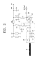
- FIG. 2 is a circuit diagram of the active antenna of FIG. 1 .
- the antenna element 10 is represented in a bar configuration. However, one will understand that the antenna element 10 may be configured such that it can be mounted internally, or externally as illustrated in FIG. 3A or FIG. 4A .
- the BPF 20 may include a low pass filter (LPF) and a high pass filter (HPF), such that the arrangement of the LPF and HPF in sequence filters the wireless signal.
- the LPF may include a first inductor L1, and first and second capacitors C1 and C2, and the HPF may include a second inductor L2, and third and fourth capacitors C4 and C5,
- the first inductor L1 and the third and fourth capacitors C4 and C5 may be coupled in series, and the first and second capacitors C1 and C2 may be arranged on a line which is branched off from the line between the first inductor L1 and the third capacitor C4.
- the first and second capacitors C1 and C2 may be arranged in parallel relation.
- the second inductor L2 may be arranged on a line which is branched off from a line between the fourth capacitor C5 and the LNA 30.
- the LNA 30 may implement a Field Effect Transistor (FET).
- FET Field Effect Transistor
- FIG. 3A is a plan view illustrating an external monopole antenna to be used as an antenna element of FIG. 1
- FIG. 3B is a graphical representation of a resonance frequency of the monopole antenna of FIG. 3A .
- a monopole antenna having a 70mm*40mm ground 11, and a 50rnm-length antenna element 10 has an operation frequency at a frequency band of 1.0GHz. Accordingly, the external antenna element 10 as shown in FIG. 3A resonates at a frequency band which is approximately five times higher than the n-equency band of a terrestrial DMB service, which is 174MHz - 216MHz.
- FIG. 4A is a plan view illustrating an internal patch antenna to be used as the antenna element of FIG. 1
- FIG. 4B is a graphical representation of a resonance frequency of the patch antenna of FIG. 4A .
- the internal patch antenna includes a 60mm*40mm ground11, a 20mm-wide antenna element 10, and has double resonance frequencies, which are 600MHz and 1.8GHz. Accordingly, the patch antenna resonates at a frequency band which is approximately three times higher than the frequency band of a terrestrial DMB service.
- the antenna element 10 is sized to accommodate the transmission and reception of mobile communication signals or RFID signals, rather than the terrestrial DMB service or the DVB-H service. Accordingly, the length of the antenna element 10 can be greatly reduced, compared to the antenna for the terrestrial DMB service or the DVB-H service.
- the antennas of FIGS. 3A and 4A are only for illustrative purposes, and the length of the antenna element 10 and the size of the ground 11 may be varied, and accordingly, the operating frequency of the external monopole antenna is variable.
- the internal patch antenna may also have a variety of configurations and sizes.
- FIG. 5 is a graphical representation illustrating the measurement of wireless signals being output from a LNA when the LNA has the BPF of FIG. 2 mounted thereon (BPF present), and when the LNA does not have the BPF of FIG. 2 mounted thereon (BPF absent).
- the antenna element 10 may implement the external monopole antenna of FIG. 3A , or the internal patch antenna of FIG. 4A .
- the antenna element 10 and the LNA 30 are not matched, if the BPF 20 is not provided.
- the operating frequency of the antenna element 10 corresponds to the length of the antenna element 10, that is, the antenna element 10 has the mobile communication frequency band as its operating frequency. Accordingly, wireless signals of a low frequency band, including the DMB service band or DVB-H service band, are not received, and the wireless signal of low frequency band is only amplified at LNA 30, but the signal cannot be extracted.
- the antenna element 10 and the LNA 30 are matched with each other, and the operating frequency of the antenna element 10 is determined according to the BPF 20.
- the antenna element 10 has the operating frequency changed to the low frequency band, and the wireless signal of low frequency band is received at the antenna element 10.
- the wireless signal of a low frequency band is then filtered through the BPF 20 such that the signal of a predetermined band such as a DMB service band or a DVB-H service band is passed, and amplified at the LNA 30.
- a wireless signal which is approximately 20dB higher than when the BPF 20 is not provided, is output.
- the experimental outputs indicate that the BPF 20 operates as a filter and as a matching circuit.
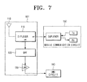
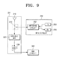
- FIGS. 6 to 9 are circuit diagrams of a mobile communication terminal having the active antenna according to an exemplary embodiment of the present invention.
- the active antenna 1 may include a power divider 15 between the antenna element 10 and the BPF 20, which operates to divide the wireless signal according to the magnitude of the power.
- the power divider 15 may divide a wireless signal being received at the antenna element 10 into a wireless signal for an 800MHz frequency of mobile communications and a wireless signal for a 200MHz band of a DMB service.
- the power divider 15 may include a first output coupled to a circuit for high frequency band wireless signals, and a second output coupled to a circuit for low frequency band wireless signals. Accordingly, a wireless signal of an 800MHz band may be passed through the first output and provided to the circuit for high frequency band wireless signals, and a wireless signal of 200MHz may be passed through the second output and provided to the circuit for high frequency band wireless signals.
- the power divider 15 may be implemented as a directional coupler.
- the circuit for high frequency band wireless signals may operate to process a wireless signal for one of mobile communication, radio frequency identification (RFID), global system for mobile communication (GSM), Wireless LAN (WLAN), Wireless Broadband Internet (WiBro), or Bluetooth.
- RFID radio frequency identification
- GSM global system for mobile communication
- WLAN Wireless LAN
- WiBro Wireless Broadband Internet
- FIGS. 6 and 7 respectively illustrate a high-frequency band wireless signal circuit 50 and 150 which processes a wireless signal for mobile communication
- FIGS. 8 and 9 illustrate a RFID circuit 250.
- the circuit 50 for mobile communication may include a duplexer 51, a receiving circuit 55 and a transmitting circuit 53.
- the duplexer 51 may divide the signal being received at the receiving circuit 55 or output at the transmitting circuit 53, according to the frequency band.
- FIGS. 6 to 9 also show a DMB circuit 60, 160, 260, and 360 respectively as the low-frequency band wireless signal circuit, which processes a wireless signal of low frequency bands such as the wireless signal of the DMB service or the DVH-B service.
- the BPF 20 and the LNA 30 of the active antenna 1 do not operate. Therefore, the operating frequency of the antenna element 10 operates in the mobile communication frequency band.
- a wireless signal in the mobile communication frequency band is transmitted and received at the antenna element 10, and the power divider 15 inputs and outputs a wireless signal at the mobile communication circuit 50, via the first output.
- the BPF 20 and the LNA 30 of the active antenna 1 operate, and the operating frequency of the antenna element 10 is converted to the DMB service frequency band by the BPF 20.
- a wireless signal received at the antenna element 10 is filtered through the BPF 20, amplified at the LNA 30 and provided to the DMB circuit 60.
- the mobile communication terminal illustrated in FIG. 7 includes a diplexer 115, instead of the power divider 15 of FIG. 6 .
- the diplexer 115 distributes signals according to the frequency band, and includes a LPF and a HPF.
- the LPF and HPF of the diplexer 115 may set their filtering bands, respectively.
- the LPF is coupled to the DMB circuit 160, and the HPF is coupled to the mobile communication circuit 150. If the filtering band of the LPF is set to 600MHz, for example, a wireless signal in low frequency band below 600MHz is provided to the DMB circuit 160, and if the HPF is set to 800MHz, the mobile communication circuit 150 receives a wireless signal of a high-frequency band above 800MHz.
- a mobile communication terminal is constructed such that a wireless signal of a high frequency band is provided to the mobile communication circuit 150 via the HPF of the diplexer 115 in a mobile communication mode, and a wireless signal of a low frequency band is selected via the LPF of the diplexer 115 in a DMB mode and is provided to the DMB circuit 160 via the BPF 120 and the LNA 130.
- FIG. 8 illustrates a mobile communication terminal as a circuit for processing a wireless signal of a high frequency band, which includes a RFID circuit 250.
- the RFID circuit 250 may include a matching circuit 252 for matching the impedance of the antenna element 210 with the RFID circuit 250, a receiving circuit 255, and a transmitting circuit 253.
- the mobile communication terminal may include a switch 215 interposed between the antenna element 210 and the BPF 220.
- the switch 215 connects the RFID circuit 250 with the antenna element 210 in a RFID mode, and connects the antenna element 210 with the BPF 220 in the DMB mode so that the active antenna 201, including the antenna element 210, the BPF 220 and the LNA 230, operates.
- the mobile communication terminal of FIG. 9 is of a similar structure as the mobile communication terminal of FIG. 8 , except that the mobile communication terminal of FIG. 9 employs a variable BPF 320 which varies the frequency band to filter. Accordingly, the frequency band of wireless signal being provided to the DMB circuit may be varied. Because the mobile communication terminal of FIG. 9 operates in a similar manner as the mobile communication terminal shown in FIG. 8 , detailed description thereof will be omitted for the sake of brevity.
- the active antenna 1 includes a BPF 20 as a matching circuit, which matches the operating frequency of the antenna element 10 with the DMB service band or the DVB-H service band.
- the DMB service or the DVB-H service may be provided, using the antenna element 10 which is sized as small as the antenna of the mobile communication terminal. As a result, the size of the antenna for the DMB service or the DVB-H service can be greatly reduced.
- the mobile communication terminal which incorporates the active antenna 1 operates the active antenna 1 during the reception of wireless signals of a low frequency band, and operates only the antenna element 10 during the transmission and reception of wireless signals of a high frequency band
- the mobile communication terminal is capable of transmitting and receiving both the wireless signals of high frequency bands such as mobile communication signals and the wireless signals of low frequency band such as the DMB service signal or the DVB-H service signal, using only one antenna. Since only one antenna is implemented, the mobile communication terminal is compact-sized.
- the size of the antenna can be greatly reduced, by the use of an active antenna which receives wireless signals of low frequency bands. Additionally, a more compact mobile communication terminal can be provided, because wireless signals of both high frequency bands and low frequency bands can be transmitted and received at one antenna.
Landscapes
- Transceivers (AREA)
- Input Circuits Of Receivers And Coupling Of Receivers And Audio Equipment (AREA)
Abstract
Description
- Apparatuses consistent with the present invention generally relate to wireless signal transmission and reception in low frequency bands using an active antenna and a mobile communication terminal having the active antenna, and more particularly, to the transmission and reception of wireless signals in low frequency bands using an active antenna, which provides a reduced antenna size and a compact-sized mobile communication terminal.
- A wide variety of services are now available through mobile communication terminals, due to the advancement of mobile communications technologies.
- The Digital Multimedia Broadcasting (DMB) or Digital Video Broadcasting-Handhelds (DVB-H) services, which receive VHF band broadcast signals and provide services, are gaining wide attention.
- DMB or DVB-H is a new concept of mobile multimedia broadcasting services which combines communications and broadcasting. The low frequency band of DMB or DVB-H services can be used through a mobile communication terminal. More specifically, the DMB service is generally classified into satellite DMB and terrestrial DMB services. The terrestrial DMB service in South Korea, for example, uses a frequency band of 174-216MHz, and the satellite DMB service uses an S-band of 2.630-2.655GHz, which is higher than the terrestrial DMB.
- The Digital Video Broadcasting-Handhelds (DVB-H) service is provided based on the Digital Video Broadcasting-Terrestrial (DVB-T), the Europe-oriented digital TV broadcast standard. The DVB-H service uses a frequency band ranging from 400MHz - 800MHz.
- The DMB services use antennas, such as a dipole antenna with a length of λ/2 or a monopole antenna with a length of λ/4. The length of the antenna decreases as the frequency band increases, and increases as the frequency band decreases. Because the terrestrial DMB service or the DVB-H service uses VHF, which is the general broadcast band, the antenna needs to have a longer length than that used in the satellite DMB. More specifically, the antenna of the terrestrial DMB system should have the same length as the TV antenna, or greater than 30cm.
- However, the terrestrial DMB has a relatively weak output which ranges between 1-2KW, because it uses
taboo channels 8, 10 and 12. Channel 8 is highly likely to have interferences with channels 7 and 9 if the output is increased. However, it will be very inconvenient if the length of the antenna is prolonged in a mobile communication terminal which has to have portability and mobility. - It is therefore very important that the antenna developers decrease the length of the antenna of the terrestrial DMB, without compromising the receptivity of the antenna. Currently, it is almost impossible for the antenna of the terrestrial DMB to operate in a length below 15cm.
- A mobile communication terminal also needs an antenna for mobile communication, to transmit and receive wireless signals. At the initial stage of the DMB and DVB-H services, an antenna for mobile communication and an antenna for DMB and DVB-H services were separately installed. Accordingly, the size of the mobile communication terminal increased, which is against the customer's demands for more compact terminals.
- Therefore, it is necessary to provide a compact antenna which is capable of transmitting and receiving wireless signals for mobile communication and signal for DMB and DVB-H services.
- An active antenna has recently gained attention as the core technology to provide miniaturization, light-weight and high-quality antennas which can keep up with the commercialization of mobile communication services and satellite communication services. An active antenna is generally constructed by directly coupling an amplifier such as a Low Noise Amplifier (LNA) to the antenna.
- In the early stage of active antennas, the antenna element and the amplifier operated as independent elements, which resulted in an increase of the overall size of the antenna. Additionally, the requirement for a matching circuit to match the antenna element with the amplifier impeded integration and efficiency of the antenna. Active antennas of higher efficiency and greater compactness were later proposed, which removed the need for a harmonic tuning circuit by regulating harmonic components generated from the amplifier.
- Accordingly, the size of the antenna could be decreased and the mobile communication terminal could also be made more compact, if an antenna for DMB and DVB-H services is constructed by incorporating the active antenna.
- According to an aspect of the present invention, there is provided an active antenna capable of transmitting and receiving a wireless signal of a low frequency band, comprising: an antenna element which transmits and receives a wireless signal, a filter which filters the wireless signal being received at the antenna element such that a wireless signal belonging to a frequency band lower than the operating frequency of the antenna element is passed, and an amplifier which amplifies the wireless signal being passed through the filter.
- The present invention aims to overcome the above disadvantages and other disadvantages not described above. Also, the present invention is not required to overcome the disadvantages described above, and an exemplary embodiment of the present invention may not overcome any of the problems described above.
- The present invention provides an active antenna, which is compact-sized to reduce the size of a mobile communication terminal incorporating the same, and is capable of transmitting and receiving a wireless signal in low frequency band, and a mobile communication terminal having the active antenna.
- The filter may comprise a band pass filter (BPF), and the BPF may comprise a high pass filter (HPF) which comprises a plurality of capacitors. The BPF may also comprise a low pass filter (LPF) which comprises a plurality of capacitors.
- The BPF may operate as a matching circuit such that the operating frequency of the antenna element is matched with a frequency band which is lower than the operating frequency of the antenna element.
- The amplifier may comprise a low noise amplifier (LNA).
- The antenna element may be sized to be suitable for transmitting and receiving a wireless signal of a frequency band which is higher than a frequency band which is lower than the operating frequency of the antenna element.
- According to another aspect of the present invention, there is provided a mobile communication terminal comprising an active antenna, the active antenna comprising an antenna element which transmits and receives a wireless signal, a filter which filters the wireless signal being received at the antenna element such that a wireless signal belonging to a frequency band lower than the operating frequency of the antenna element is passed, and an amplifier which amplifies the wireless signal being passed through the filter, a low frequency circuit which processes a wireless signal of a low frequency band being received at the active antenna, a high frequency circuit which processes a wireless signal of an operating frequency band being transmitted and received at the antenna element, and a selective connecting unit which selectively connects the antenna element with one of the high frequency circuit and the low frequency circuit.
- The low frequency circuit may process at least one of a wireless signal for Digital Multimedia Broadcasting (DMB) service, and a wireless signal for Digital Video Broadcasting-Handhelds (DVB-H) service to a form suitable for output.
- The high frequency circuit may process at least one of a wireless signal for mobile communication, a wireless signal for radio frequency identification (RFID), a wireless signal for global system for mobile communication (GSM), a wireless signal for Wireless LAN (WLAN), a wireless signal for Wireless Broadband Internet (WiBro), and a wireless signal for Bluetooth communication to a form suitable for output.
- The low frequency circuit may be coupled to the amplifier of the active antenna, and the high frequency circuit may be coupled to the antenna element.
- The selective connecting unit may be interposed between the antenna element and the filter, and connect the antenna element with one of the filter and the high frequency circuit.
- The selective connecting unit may comprise at least one of a power divider, a directional coupler, a diplexer, and a switch.
- The filter may comprise a variable band pass filter (BPF) which is capable of varying filtering band.
- These and other aspects of the present invention will become more apparent and more readily appreciated from the following description of exemplary embodiments thereof, with reference to the accompanying drawings, in which:
-
FIG. 1 is a block diagram of an active antenna according to an exemplary embodiment of the present invention; -
FIG. 2 is a circuit diagram of the active antenna ofFIG. 1 ; -
FIG. 3A is a plan view illustrating an external monopole antenna to be used as an antenna element ofFIG. 1 ; -
FIG. 3B is a graphical representation of a resonance frequency of the monopole antenna ofFIG. 3A ; -
FIG. 4A is a plan view illustrating an internal patch antenna to be used as the antenna element ofFIG. 1 ; -
FIG. 4B is a graphical representation of a resonance frequency of the patch antenna ofFIG. 4A ; -
FIG. 5 is a graphical representation illustrating the measurement of wireless signal being output from a Low noise Amplifier (LNA) when the LNA has the BPF ofFIG. 2 mounted thereon (BPF present), and when the LNA does not have the BPF ofFIG. 2 mounted thereon (BPF absent); and -
FIGS. 6 to 9 are circuit diagrams illustrating a mobile communication terminal incorporating the active antenna according to an exemplary embodiment of the present invention. - Certain exemplary embodiments of the present invention will now be described in greater detail with reference to the accompanying drawings.
- In the following description, the same drawing reference numerals are used to refer to the same elements, even in different drawings. The matters defined in the following description, such as detailed construction and element descriptions, are provided as examples to assist in a comprehensive understanding of the invention. Also, well-known functions or constructions are not described in detail, since they would obscure the invention in unnecessary detail.
- Also in the following description, the active antenna and the mobile communication terminal may be configured to handle the transmission and processing of wireless signals of a low frequency band, such as a terrestrial DMB service or a DVB-H service. Also in the later part of the description, the 'DMB' may refer to terrestrial DMB.
-
FIG. 1 is a block diagram of an active antenna according to an exemplary embodiment of the present invention. - The active antenna may include an
antenna element 10, a band pass filter (BPF) 20, and a low noise amplifier (LNA) 30. A wireless signal which is sent from theLNA 30 is provided to aDMB processing circuit 60. AlthoughFIG. 1 illustratesLNA 30 coupled only with theDMB processing circuit 60, one will understand that theLNA 30 may be coupled to a variety of circuits such as a DVB-H processing circuit, circuits which process low frequency band wireless signals, or the like. - The
antenna element i 0 may be mounted externally or internally, and sized so that it would not resonate with the low frequency band for the terrestrial DMB service or the DVB-H service, but would resonate with a high frequency band, i.e., a frequency band that is several hundred times higher than the low frequency band, such as the frequency band for the transmission and reception of mobile communication signals or the transmission and reception of RFID signals. The configurations, sizes and resonance frequencies of theantenna element 10 will be explained in greater detail below. - The
BPF 20 filters a wireless signal being received at theantenna element 10 such that only a signal of a predetermined frequency band, such as a DMB service band or a DVB-H service band can pass. Additionally, theBPF 20 operates as a matching circuit between theantenna element 10 and theLNA 30. Accordingly, it is not necessary to install a separate matching circuit because theantenna element 10, which is sized to transmit and receive mobile communication signals, is capable of receiving wireless signals of terrestrial DMB services or DVB-H services based on the matching operation of theBPF 20. - The
LNA 30 operates to amplify the wireless signal being passed through theBPF 20, and also minimize any noise in the wireless signal. -
FIG. 2 is a circuit diagram of the active antenna ofFIG. 1 . - Referring to
FIG. 2 , theantenna element 10 is represented in a bar configuration. However, one will understand that theantenna element 10 may be configured such that it can be mounted internally, or externally as illustrated inFIG. 3A orFIG. 4A . - The
BPF 20 may include a low pass filter (LPF) and a high pass filter (HPF), such that the arrangement of the LPF and HPF in sequence filters the wireless signal. The LPF may include a first inductor L1, and first and second capacitors C1 and C2, and the HPF may include a second inductor L2, and third and fourth capacitors C4 and C5, The first inductor L1 and the third and fourth capacitors C4 and C5 may be coupled in series, and the first and second capacitors C1 and C2 may be arranged on a line which is branched off from the line between the first inductor L1 and the third capacitor C4. The first and second capacitors C1 and C2 may be arranged in parallel relation. The second inductor L2 may be arranged on a line which is branched off from a line between the fourth capacitor C5 and theLNA 30. - The
LNA 30 may implement a Field Effect Transistor (FET). -
FIG. 3A is a plan view illustrating an external monopole antenna to be used as an antenna element ofFIG. 1 , andFIG. 3B is a graphical representation of a resonance frequency of the monopole antenna ofFIG. 3A . - As shown in
FIGS. 3A and3B , a monopole antenna having a 70mm*40mm ground 11, and a 50rnm-length antenna element 10 has an operation frequency at a frequency band of 1.0GHz. Accordingly, theexternal antenna element 10 as shown inFIG. 3A resonates at a frequency band which is approximately five times higher than the n-equency band of a terrestrial DMB service, which is 174MHz - 216MHz. -
FIG. 4A is a plan view illustrating an internal patch antenna to be used as the antenna element ofFIG. 1 , andFIG. 4B is a graphical representation of a resonance frequency of the patch antenna ofFIG. 4A . - As shown in
FIGS. 4A and4B , the internal patch antenna includes a 60mm*40mm ground11, a 20mm-wide antenna element 10, and has double resonance frequencies, which are 600MHz and 1.8GHz. Accordingly, the patch antenna resonates at a frequency band which is approximately three times higher than the frequency band of a terrestrial DMB service. - As explained above, the
antenna element 10 is sized to accommodate the transmission and reception of mobile communication signals or RFID signals, rather than the terrestrial DMB service or the DVB-H service. Accordingly, the length of theantenna element 10 can be greatly reduced, compared to the antenna for the terrestrial DMB service or the DVB-H service. The antennas ofFIGS. 3A and4A are only for illustrative purposes, and the length of theantenna element 10 and the size of theground 11 may be varied, and accordingly, the operating frequency of the external monopole antenna is variable. Likewise, the internal patch antenna may also have a variety of configurations and sizes. -
FIG. 5 is a graphical representation illustrating the measurement of wireless signals being output from a LNA when the LNA has the BPF ofFIG. 2 mounted thereon (BPF present), and when the LNA does not have the BPF ofFIG. 2 mounted thereon (BPF absent). - The
antenna element 10 may implement the external monopole antenna ofFIG. 3A , or the internal patch antenna ofFIG. 4A . - As shown, the
antenna element 10 and theLNA 30 are not matched, if theBPF 20 is not provided. In this case, the operating frequency of theantenna element 10 corresponds to the length of theantenna element 10, that is, theantenna element 10 has the mobile communication frequency band as its operating frequency. Accordingly, wireless signals of a low frequency band, including the DMB service band or DVB-H service band, are not received, and the wireless signal of low frequency band is only amplified atLNA 30, but the signal cannot be extracted. - If the
BPF 20 is provided, theantenna element 10 and theLNA 30 are matched with each other, and the operating frequency of theantenna element 10 is determined according to theBPF 20. As a result, theantenna element 10 has the operating frequency changed to the low frequency band, and the wireless signal of low frequency band is received at theantenna element 10. The wireless signal of a low frequency band is then filtered through theBPF 20 such that the signal of a predetermined band such as a DMB service band or a DVB-H service band is passed, and amplified at theLNA 30. As a result, a wireless signal, which is approximately 20dB higher than when theBPF 20 is not provided, is output. The experimental outputs indicate that theBPF 20 operates as a filter and as a matching circuit. -
FIGS. 6 to 9 are circuit diagrams of a mobile communication terminal having the active antenna according to an exemplary embodiment of the present invention. - Referring to
FIG. 6 , theactive antenna 1 may include apower divider 15 between theantenna element 10 and theBPF 20, which operates to divide the wireless signal according to the magnitude of the power. In one exemplary implementation, thepower divider 15 may divide a wireless signal being received at theantenna element 10 into a wireless signal for an 800MHz frequency of mobile communications and a wireless signal for a 200MHz band of a DMB service. - The
power divider 15 may include a first output coupled to a circuit for high frequency band wireless signals, and a second output coupled to a circuit for low frequency band wireless signals. Accordingly, a wireless signal of an 800MHz band may be passed through the first output and provided to the circuit for high frequency band wireless signals, and a wireless signal of 200MHz may be passed through the second output and provided to the circuit for high frequency band wireless signals. Thepower divider 15 may be implemented as a directional coupler. - The circuit for high frequency band wireless signals may operate to process a wireless signal for one of mobile communication, radio frequency identification (RFID), global system for mobile communication (GSM), Wireless LAN (WLAN), Wireless Broadband Internet (WiBro), or Bluetooth.
FIGS. 6 and7 respectively illustrate a high-frequency bandwireless signal circuit FIGS. 8 and9 illustrate aRFID circuit 250. Thecircuit 50 for mobile communication may include aduplexer 51, a receivingcircuit 55 and a transmittingcircuit 53. Theduplexer 51 may divide the signal being received at the receivingcircuit 55 or output at the transmittingcircuit 53, according to the frequency band. -
FIGS. 6 to 9 also show aDMB circuit - When a mobile communication terminal operates in a mobile communication mode in which a wireless signal for mobile communication is transmitted and received, the
BPF 20 and theLNA 30 of theactive antenna 1 do not operate. Therefore, the operating frequency of theantenna element 10 operates in the mobile communication frequency band. A wireless signal in the mobile communication frequency band is transmitted and received at theantenna element 10, and thepower divider 15 inputs and outputs a wireless signal at themobile communication circuit 50, via the first output. - When the mobile communication terminal operates in a DMB mode in which a wireless signal of a DMB service is transmitted and received, the
BPF 20 and theLNA 30 of theactive antenna 1 operate, and the operating frequency of theantenna element 10 is converted to the DMB service frequency band by theBPF 20. As a result, a wireless signal received at theantenna element 10 is filtered through theBPF 20, amplified at theLNA 30 and provided to theDMB circuit 60. - The mobile communication terminal illustrated in
FIG. 7 includes adiplexer 115, instead of thepower divider 15 ofFIG. 6 . Thediplexer 115 distributes signals according to the frequency band, and includes a LPF and a HPF. The LPF and HPF of thediplexer 115 may set their filtering bands, respectively. The LPF is coupled to theDMB circuit 160, and the HPF is coupled to themobile communication circuit 150. If the filtering band of the LPF is set to 600MHz, for example, a wireless signal in low frequency band below 600MHz is provided to theDMB circuit 160, and if the HPF is set to 800MHz, themobile communication circuit 150 receives a wireless signal of a high-frequency band above 800MHz. - A mobile communication terminal according to an exemplary embodiment of the present invention is constructed such that a wireless signal of a high frequency band is provided to the
mobile communication circuit 150 via the HPF of thediplexer 115 in a mobile communication mode, and a wireless signal of a low frequency band is selected via the LPF of thediplexer 115 in a DMB mode and is provided to theDMB circuit 160 via theBPF 120 and theLNA 130. -
FIG. 8 illustrates a mobile communication terminal as a circuit for processing a wireless signal of a high frequency band, which includes aRFID circuit 250. - The
RFID circuit 250 may include amatching circuit 252 for matching the impedance of theantenna element 210 with theRFID circuit 250, a receivingcircuit 255, and a transmittingcircuit 253. - The mobile communication terminal according to an exemplary embodiment of the present invention may include a
switch 215 interposed between theantenna element 210 and theBPF 220. Theswitch 215 connects theRFID circuit 250 with theantenna element 210 in a RFID mode, and connects theantenna element 210 with theBPF 220 in the DMB mode so that theactive antenna 201, including theantenna element 210, theBPF 220 and theLNA 230, operates. - The mobile communication terminal of
FIG. 9 is of a similar structure as the mobile communication terminal ofFIG. 8 , except that the mobile communication terminal ofFIG. 9 employs avariable BPF 320 which varies the frequency band to filter. Accordingly, the frequency band of wireless signal being provided to the DMB circuit may be varied. Because the mobile communication terminal ofFIG. 9 operates in a similar manner as the mobile communication terminal shown inFIG. 8 , detailed description thereof will be omitted for the sake of brevity. - As explained above, the
active antenna 1 according to an exemplary embodiment of the present invention includes aBPF 20 as a matching circuit, which matches the operating frequency of theantenna element 10 with the DMB service band or the DVB-H service band. With the use of theactive antenna 1, the DMB service or the DVB-H service may be provided, using theantenna element 10 which is sized as small as the antenna of the mobile communication terminal. As a result, the size of the antenna for the DMB service or the DVB-H service can be greatly reduced. - Since the mobile communication terminal which incorporates the
active antenna 1 according to the exemplary embodiment of the present invention operates theactive antenna 1 during the reception of wireless signals of a low frequency band, and operates only theantenna element 10 during the transmission and reception of wireless signals of a high frequency band, the mobile communication terminal is capable of transmitting and receiving both the wireless signals of high frequency bands such as mobile communication signals and the wireless signals of low frequency band such as the DMB service signal or the DVB-H service signal, using only one antenna. Since only one antenna is implemented, the mobile communication terminal is compact-sized. - As mentioned above, according to the exemplary embodiments of the present invention, the size of the antenna can be greatly reduced, by the use of an active antenna which receives wireless signals of low frequency bands. Additionally, a more compact mobile communication terminal can be provided, because wireless signals of both high frequency bands and low frequency bands can be transmitted and received at one antenna.
- Aspects of the invention may be summarised as follows:
- A. An active antenna capable of transmitting and receiving a wireless signal of a low frequency band, comprising: an antenna element which transmits and receives the wireless signal; a filter which filters the wireless signal being received at the antenna element such that a wireless signal belonging to a frequency band lower than an operating frequency of the antenna element is passed; and an amplifier which amplifies the wireless signal being passed through the filter.
- B. The active antenna of A wherein the filter comprises a band pass filter (BPF).
- C. The active antenna of B, wherein the BPF comprises a high pass filter (HPF) which comprises a plurality of capacitors.
- D. The active antenna of B, wherein the BPF comprises a low pass filter (LPF) which comprises a plurality of capacitors.
- E. The active antenna of B, wherein the BPF operates as a matching circuit such that the operating frequency of the antenna element is matched with a frequency band which is lower than the operating frequency of the antenna element.
- F. The active antenna of A, wherein the amplifier comprises a low noise amplifier (LNA).
- G. The active antenna of A, wherein the antenna element is sized to be suitable for transmitting and receiving a wireless signal of a frequency band which is higher than a frequency band which is lower than the operating frequency of the antenna element.
- H. A mobile communication terminal comprising an active antenna, the active antenna comprising: an antenna element which transmits and receives a wireless signal; a filter which filters the wireless signal being received at the antenna element such that a wireless signal belonging to a frequency band lower than an operating frequency of the antenna element is passed; an amplifier which amplifies the wireless signal being passed through the filter; a low frequency circuit which processes wireless signals of a low frequency band being received at the active antenna; a high frequency circuit which processes wireless signals of an operating frequency band being transmitted and received at the antenna element; and a selective connecting unit which selectively connects the antenna element with one of the high frequency circuit and the low frequency circuit.
- I. The mobile communication terminal of H, wherein the low frequency circuit processes at least one of a wireless signal for a Digital Multimedia Broadcasting (DMB) service, and a wireless signal for a Digital Video Broadcasting-Handhelds (DVB-H) service and outputs the processed signal.
- J. The mobile communication terminal of H, wherein the high frequency circuit processes at least one of a wireless signal for mobile communication, a wireless signal for radio frequency identification (RFID), a wireless signal for global system for mobile communication (GSM), a wireless signal for Wireless LAN (WLAN), a wireless signal for Wireless Broadband Internet (WiBro), and a wireless signal for Bluetooth communication and outputs the processed signal.
- K. The mobile communication terminal of H, wherein the low frequency circuit is coupled to the amplifier of the active antenna, and the high frequency circuit is coupled to the antenna element.
- L. The mobile communication terminal of H, wherein the selective connecting unit is interposed between the antenna element and the filter, and connects the antenna element with one of the filter and the high frequency circuit.
- M. The mobile communication terminal of H, wherein the selective connecting unit comprises at least one of a power divider, a directional coupler, a diplexer, and a switch.
- N. The mobile communication terminal of H, wherein the filter comprises a band pass filter (BPF).
- O. The mobile communication terminal of H, wherein the filter comprises a variable band pass filter (HPF) which is capable of varying a filtering band.
- Although a few exemplary embodiments of the present general inventive concept have been shown and described, it will be appreciated by those skilled in the art that changes may be made in these exemplary embodiments without departing from the scope of which is defined in the appended claims
Claims (15)
- An active antenna capable of transmitting and receiving a wireless signal of a low frequency band, comprising:an antenna element (10) which transmits and receives the wireless signal;a filter (20); andan amplifier (30) which amplifies the wireless signal being passed through the filter,and characterized in that:the antenna element (10) is sized to accommodate the transmission and reception of mobile communication signals or RFID signals; andthe filter (20) is adapted to filter the wireless signal being received at the antenna element such that a wireless signal belonging to a frequency band lower than an operating frequency of the antenna element is passed.
- The active antenna of claim 1, wherein the filter (20) comprises a band pass filter (BPF).
- The active antenna of claim 2, wherein the BPF comprises a high pass filter (HPF) which comprises a plurality of capacitors,
- The active antenna of claim 2, wherein the BPF comprises a low pass filter (LPF) which comprises a plurality of capacitors.
- The active antenna of claim 2, wherein the BPF operates as a matching circuit such that the operating frequency of the antenna element (10) is matched with a frequency band which is lower than the operating frequency of the antenna element (10).
- The active antenna of any preceding claim, wherein the amplifier (30) comprises a low noise amplifier (LNA).
- The active antenna of any preceding claim, wherein the antenna element (10) is sized to be suitable for transmitting and receiving a wireless signal of a frequency band which is higher than a frequency band which is lower than the operating frequency of the antenna element (10).
- A mobile communication terminal comprising an active antenna, the active antenna comprising:the active antenna of any preceding claim;a low frequency circuit which processes wireless signals of a low frequency band being received at the active antenna;a high frequency circuit which processes wireless signals of an operating frequency band being transmitted and received at the antenna element; anda selective connecting unit which selectively connects the antenna element with one of the high frequency circuit and the low frequency circuit.
- The mobile communication terminal of claim 8, wherein the low frequency circuit processes at least one of a wireless signal for a Digital Multimedia Broadcasting (DMB) service, and a wireless signal for a Digital Video Broadcasting-Handhelds (DVB-H) service and outputs the processed signal.
- The mobile communication terminal of claim 8 or 9, wherein the high frequency circuit processes at least one of a wireless signal for mobile communication, a wireless signal for radio frequency identification (RFID), a wireless signal for global system for mobile communication (GSM), a wireless signal for Wireless LAN (WLAN), a wireless signal for Wireless Broadband Internet (WiBro), and a wireless signal for Bluetooth communication and outputs the processed signal.
- The mobile communication terminal of any one of claims 8 to 10, wherein the low frequency circuit is coupled to the amplifier of the active antenna, and the high frequency circuit is coupled to the antenna element.
- The mobile communication terminal of any one of claims 8 to 11, wherein the selective connecting unit is interposed between the antenna element and the filter, and connects the antenna element with one of the filter and the high frequency circuit.
- The mobile communication terminal of any one of claims 8 to 12, wherein the selective connecting unit comprises at least one of a power divider, a directional coupler, a diplexer, and a switch.
- The mobile communication terminal of any one of claims 8 to 13, wherein the filter comprises a band pass filter (BPF).
- The mobile communication terminal of any one of claims 8 to 14, wherein the filter comprises a variable band pass filter (BPF) which is capable of varying a filtering band.
Applications Claiming Priority (2)
| Application Number | Priority Date | Filing Date | Title |
|---|---|---|---|
| KR1020060101898A KR100822475B1 (en) | 2006-10-19 | 2006-10-19 | Active antenna capable of transmitting and receiving low frequency radio signals and a mobile communication terminal having the same |
| EP07115433A EP1914829A1 (en) | 2006-10-19 | 2007-08-31 | Active antenna capable of wireless signal transmission and reception and mobile communication terminal having the same |
Related Parent Applications (1)
| Application Number | Title | Priority Date | Filing Date |
|---|---|---|---|
| EP07115433.0 Division | 2007-08-31 |
Publications (1)
| Publication Number | Publication Date |
|---|---|
| EP2190063A1 true EP2190063A1 (en) | 2010-05-26 |
Family
ID=38814265
Family Applications (2)
| Application Number | Title | Priority Date | Filing Date |
|---|---|---|---|
| EP07115433A Ceased EP1914829A1 (en) | 2006-10-19 | 2007-08-31 | Active antenna capable of wireless signal transmission and reception and mobile communication terminal having the same |
| EP10156112A Withdrawn EP2190063A1 (en) | 2006-10-19 | 2007-08-31 | Active antenna capable of wireless signal transmission and reception and mobile communication terminal having the same |
Family Applications Before (1)
| Application Number | Title | Priority Date | Filing Date |
|---|---|---|---|
| EP07115433A Ceased EP1914829A1 (en) | 2006-10-19 | 2007-08-31 | Active antenna capable of wireless signal transmission and reception and mobile communication terminal having the same |
Country Status (4)
| Country | Link |
|---|---|
| US (1) | US20080094304A1 (en) |
| EP (2) | EP1914829A1 (en) |
| JP (1) | JP2008104176A (en) |
| KR (1) | KR100822475B1 (en) |
Cited By (1)
| Publication number | Priority date | Publication date | Assignee | Title |
|---|---|---|---|---|
| CN110299618A (en) * | 2014-01-23 | 2019-10-01 | 华为终端有限公司 | A kind of antenna system and terminal |
Families Citing this family (14)
| Publication number | Priority date | Publication date | Assignee | Title |
|---|---|---|---|---|
| USD582903S1 (en) * | 2007-09-06 | 2008-12-16 | Advanced Automotive Antennas, S.L. | Aerial |
| USD585436S1 (en) * | 2008-02-19 | 2009-01-27 | Advanced Connection Technology Inc. | Antenna |
| USD608769S1 (en) * | 2008-07-11 | 2010-01-26 | Muehlbauer Ag | UHF antenna |
| KR100986049B1 (en) * | 2008-08-11 | 2010-10-07 | 주식회사 에이스테크놀로지 | Modular active antenna for multicast reception |
| US8682261B2 (en) | 2009-02-13 | 2014-03-25 | Qualcomm Incorporated | Antenna sharing for wirelessly powered devices |
| JP5380685B2 (en) * | 2009-03-25 | 2014-01-08 | Necネットワークプロダクツ株式会社 | Multi-frequency receiving system |
| EP2416442B1 (en) * | 2009-04-02 | 2017-03-22 | Amotech Co., Ltd. | Internal antenna module |
| KR20100133536A (en) * | 2009-06-12 | 2010-12-22 | 삼성전자주식회사 | Built-in antenna device of folder type portable terminal |
| KR101140958B1 (en) | 2010-01-29 | 2012-07-12 | 주식회사 팬택 | Mobile apparatus based DS-UWB |
| TWD153071S (en) * | 2011-06-30 | 2013-04-21 | 橫須賀電信研究園區股份有限公司 | Antenna for wireless communication |
| TWD148864S (en) * | 2011-06-30 | 2012-08-21 | 橫須賀電信研究園區股份有限公司 | Antenna for wireless communication |
| TWD153072S (en) * | 2011-09-13 | 2013-04-21 | 橫須賀電信研究園區股份有限公司 | Antenna for wireless communication |
| USD1011326S1 (en) * | 2022-02-02 | 2024-01-16 | Jayshri Sharad Kulkarni | MIMO antenna |
| USD1010628S1 (en) * | 2022-02-02 | 2024-01-09 | Jayshri Sharad Kulkarni | Four-port MIMO antenna with whirligig isolating structure |
Citations (3)
| Publication number | Priority date | Publication date | Assignee | Title |
|---|---|---|---|---|
| EP1545013A1 (en) | 2003-08-07 | 2005-06-22 | Matsushita Electric Industrial Co., Ltd. | Matching unit and receiver apparatus using the same |
| EP1659707A2 (en) * | 2004-11-22 | 2006-05-24 | LG Electronics Inc. | Apparatus and method for processing digital multimedia broadcast (dmb) signals |
| US20060214857A1 (en) | 2005-03-24 | 2006-09-28 | Nokia Corporation | Internal digital TV antennas for hand-held telecommunications device |
Family Cites Families (22)
| Publication number | Priority date | Publication date | Assignee | Title |
|---|---|---|---|---|
| US5758266A (en) | 1994-09-30 | 1998-05-26 | Qualcomm Incorporated | Multiple frequency communication device |
| US5907798A (en) * | 1996-06-21 | 1999-05-25 | Lucent Technologies Inc. | Wireless telephone intermodulation performance enhancement techniques |
| US5926751A (en) | 1997-02-19 | 1999-07-20 | Motorola, Inc. | Method and apparatus for receiving communication signals |
| JPH11122128A (en) * | 1997-10-17 | 1999-04-30 | Matsushita Electric Ind Co Ltd | Wireless communication and broadcasting equipment |
| US6233438B1 (en) * | 1998-03-26 | 2001-05-15 | Ericsson Inc. | Wide-range power control systems and methods for radio frequency transmitters and mobile radiotelephones |
| KR20020063777A (en) * | 2001-01-30 | 2002-08-05 | (주)컴뮤웍스 | Dual polarization diversity active base station antenna for IMT2000 and PCS |
| KR100396779B1 (en) * | 2001-07-12 | 2003-09-02 | 엘지전자 주식회사 | Mobile communication apparatus |
| KR100442833B1 (en) * | 2002-07-12 | 2004-08-02 | 삼성전자주식회사 | Method and apparatus of multi-band RF receiver in mobile unit communication system |
| US6949979B2 (en) * | 2002-12-05 | 2005-09-27 | Memetics Technology Co. LTD | Designing methods and circuits for multi-band electronic circuits |
| KR100925430B1 (en) * | 2002-12-28 | 2009-11-06 | 엘지전자 주식회사 | RF switch |
| JP2004289595A (en) * | 2003-03-24 | 2004-10-14 | Matsushita Electric Ind Co Ltd | Antenna circuit |
| JP4207641B2 (en) * | 2003-04-16 | 2009-01-14 | パナソニック株式会社 | Portable receiver |
| US7099643B2 (en) * | 2003-05-27 | 2006-08-29 | Broadcom Corporation | Analog open-loop VCO calibration method |
| JP4298468B2 (en) | 2003-10-31 | 2009-07-22 | シャープ株式会社 | Frequency conversion circuit, radio frequency receiver, and radio frequency transceiver |
| EP1703648A1 (en) * | 2004-01-09 | 2006-09-20 | Mitsubishi Denki Kabushiki Kaisha | Receiver and transmitter/receiver |
| US7773702B2 (en) * | 2004-05-03 | 2010-08-10 | Qualcomm Incorporated | Gain control for a receiver in a multi-carrier communication system |
| JP3904004B2 (en) * | 2004-07-01 | 2007-04-11 | 松下電器産業株式会社 | Matching device and portable receiver using the same |
| JP3972928B2 (en) * | 2004-09-13 | 2007-09-05 | 松下電器産業株式会社 | Matching device, duplexer using the same, and portable receiver using the same |
| US7522016B2 (en) * | 2004-09-15 | 2009-04-21 | Qualcomm, Incorporated | Tunable surface acoustic wave resonators |
| KR20060064359A (en) * | 2004-12-08 | 2006-06-13 | 주식회사 팬택앤큐리텔 | Satellite digital multimedia broadcasting signal receiving device and mobile communication terminal using same |
| US7202740B2 (en) * | 2005-01-05 | 2007-04-10 | Broadcom Corporation | Gain boosting for tuned differential LC circuits |
| US7460890B2 (en) * | 2005-07-28 | 2008-12-02 | Texas Instruments Incorporated | Bi-modal RF architecture for low power devices |
-
2006
- 2006-10-19 KR KR1020060101898A patent/KR100822475B1/en not_active Expired - Fee Related
-
2007
- 2007-03-16 US US11/723,098 patent/US20080094304A1/en not_active Abandoned
- 2007-08-31 EP EP07115433A patent/EP1914829A1/en not_active Ceased
- 2007-08-31 EP EP10156112A patent/EP2190063A1/en not_active Withdrawn
- 2007-10-11 JP JP2007265584A patent/JP2008104176A/en active Pending
Patent Citations (3)
| Publication number | Priority date | Publication date | Assignee | Title |
|---|---|---|---|---|
| EP1545013A1 (en) | 2003-08-07 | 2005-06-22 | Matsushita Electric Industrial Co., Ltd. | Matching unit and receiver apparatus using the same |
| EP1659707A2 (en) * | 2004-11-22 | 2006-05-24 | LG Electronics Inc. | Apparatus and method for processing digital multimedia broadcast (dmb) signals |
| US20060214857A1 (en) | 2005-03-24 | 2006-09-28 | Nokia Corporation | Internal digital TV antennas for hand-held telecommunications device |
Non-Patent Citations (1)
| Title |
|---|
| MEINKE H, GUNDLACH F W: "Taschenbuch der Hochfrequenztechnik Bd. 2 Komponenten", 1992, SPRINGER VERLAG, BERLIN HEIDELBERG NEW YORK, ISBN: 3540547150, XP002462630 * |
Cited By (2)
| Publication number | Priority date | Publication date | Assignee | Title |
|---|---|---|---|---|
| CN110299618A (en) * | 2014-01-23 | 2019-10-01 | 华为终端有限公司 | A kind of antenna system and terminal |
| US11949172B2 (en) | 2014-01-23 | 2024-04-02 | Honor Device Co., Ltd. | Antenna system and terminal |
Also Published As
| Publication number | Publication date |
|---|---|
| KR100822475B1 (en) | 2008-04-16 |
| EP1914829A1 (en) | 2008-04-23 |
| US20080094304A1 (en) | 2008-04-24 |
| JP2008104176A (en) | 2008-05-01 |
Similar Documents
| Publication | Publication Date | Title |
|---|---|---|
| EP1914829A1 (en) | Active antenna capable of wireless signal transmission and reception and mobile communication terminal having the same | |
| US6943746B2 (en) | Radio device and antenna structure | |
| CN106299598B (en) | Electronic device and its multi-feed antenna | |
| CN111052501B (en) | Antenna device and mobile terminal | |
| US7928909B2 (en) | Concurrent mode antenna system | |
| US8339321B2 (en) | Antenna device and portable radio apparatus | |
| KR20010014372A (en) | Impedance matching circuit for power amplifier | |
| WO2005036778A1 (en) | Method and apparatus to provide an area efficient antenna divesity receiver | |
| US20110234469A1 (en) | Wireless communication terminal | |
| KR20120050620A (en) | Device for receiving dual band signal using multi-band antenna in wireless receiver | |
| JP4875166B2 (en) | Device that allows two elements to share a common feed | |
| JP2004112397A (en) | Multi-frequency shared antenna and multi-band transmitter-receiver | |
| KR20120050618A (en) | Ear phone antenna device for receiving dual band signal | |
| US20110128193A1 (en) | Card device for wireless communication | |
| EP1536513A1 (en) | Cellulare phone capable of receiving a plurality of broadcast waves | |
| US20120120322A1 (en) | Portable wireless device | |
| US10581166B2 (en) | Reconfigurable multi-band antenna with independent control | |
| JP2004274445A (en) | Antenna device and radio equipment | |
| JP2007013965A (en) | Variable antenna control unit through data signal line | |
| JP2009296281A (en) | Multi-band antenna | |
| JP2010226579A (en) | Multiple frequency reception system | |
| JP4670741B2 (en) | Power amplifier | |
| US20080030419A1 (en) | Antenna Device | |
| EP1796211A1 (en) | Antenna for portable terminal and portable terminal | |
| JP2006135995A (en) | Antenna module for receiving broadcast frequency band signals |
Legal Events
| Date | Code | Title | Description |
|---|---|---|---|
| PUAI | Public reference made under article 153(3) epc to a published international application that has entered the european phase |
Free format text: ORIGINAL CODE: 0009012 |
|
| AC | Divisional application: reference to earlier application |
Ref document number: 1914829 Country of ref document: EP Kind code of ref document: P |
|
| AK | Designated contracting states |
Kind code of ref document: A1 Designated state(s): DE FR GB |
|
| 17P | Request for examination filed |
Effective date: 20101124 |
|
| RAP1 | Party data changed (applicant data changed or rights of an application transferred) |
Owner name: SAMSUNG ELECTRONICS CO., LTD. Owner name: SAMSUNG ELECTRO-MECHANICS CO., LTD |
|
| 17Q | First examination report despatched |
Effective date: 20141110 |
|
| STAA | Information on the status of an ep patent application or granted ep patent |
Free format text: STATUS: THE APPLICATION IS DEEMED TO BE WITHDRAWN |
|
| 18D | Application deemed to be withdrawn |
Effective date: 20150321 |