EP2189799A1 - Apparatus and method for three-pole type measuring of specific soil resistance for distribution grounding - Google Patents
Apparatus and method for three-pole type measuring of specific soil resistance for distribution grounding Download PDFInfo
- Publication number
- EP2189799A1 EP2189799A1 EP08169622A EP08169622A EP2189799A1 EP 2189799 A1 EP2189799 A1 EP 2189799A1 EP 08169622 A EP08169622 A EP 08169622A EP 08169622 A EP08169622 A EP 08169622A EP 2189799 A1 EP2189799 A1 EP 2189799A1
- Authority
- EP
- European Patent Office
- Prior art keywords
- resistance
- specific soil
- electrode
- soil resistance
- screw
- Prior art date
- Legal status (The legal status is an assumption and is not a legal conclusion. Google has not performed a legal analysis and makes no representation as to the accuracy of the status listed.)
- Withdrawn
Links
Images




Classifications
-
- G—PHYSICS
- G01—MEASURING; TESTING
- G01R—MEASURING ELECTRIC VARIABLES; MEASURING MAGNETIC VARIABLES
- G01R27/00—Arrangements for measuring resistance, reactance, impedance, or electric characteristics derived therefrom
- G01R27/02—Measuring real or complex resistance, reactance, impedance, or other two-pole characteristics derived therefrom, e.g. time constant
- G01R27/20—Measuring earth resistance; Measuring contact resistance, e.g. of earth connections, e.g. plates
Definitions
- the present invention relates to specific soil resistance measurement, and, more particularly, to an apparatus and method for measuring a specific soil resistance for distribution grounding, which uses three electrodes to measure the specific soil resistance as well as an earth resistance based on a three-electrode method in specific soil resistance measurement that is the most basic but likely to be overlooked in a practical distribution work.
- an apparatus for measuring a specific soil resistance for distribution has an advantage in that it facilitates measurement of the specific soil resistance at a point where the ground rod is buried.
- the four-electrode method used for the grounding work relating to power transmission systems measures the specific soil resistance of a large area, such as the substation grounding, the tower grounding, and the like, several times and obtains an average of the measured resistances.
- the distribution work is sporadically and widely carried out in a very small region associated with installation of a ground rod, the four-electrode method is inconvenient and thus rarely utilized.
- Fig. 1 is a view of a conventional four-electrode method for measuring the specific soil resistance.
- c1 ⁇ c2 are power connections; p1 ⁇ p2 are potential difference measurements; 1 is a length of a grounded electrode; a is a distance between the grounded electrodes; V is a voltage; and I is a current.
- Wenner's four-electrode method is a method of arranging four electrodes at regular intervals in a straight line, which was published by Frank Wenner in 1915 and is the most frequently used method for measuring the specific soil resistance.
- the soil resistivity is measured under a condition of a ⁇ 20d since it is preferable to apply the four-electrode or four-point method to measurement.
- Expression 1 represents a mean soil resistivity of soil at an approximate depth of (0.75 ⁇ 1)a.
- the soil resistivity is calculated regardless of the test voltage, current, and earth resistances at c1, c2, p1, and p2. If the distance "a" between the electrodes is large, the mean soil resistivity is measured at a depth as deep as the test current reaches. If a water pipe, a gas pipe or similar metal pipe is buried under the ground, the test current may be bypassed via such a conductive metal so that an error may occur. Therefore, to correctly measure the soil resistivity through the four-electrode method, it is desirable that the soil resistivity be measured many times and averaged while changing the arranging direction and the intervals of the four electrodes.
- Fig. 2 is a graph depicting a general correlation between a specific resistance ( ⁇ ) and a distance (a) between the electrodes. As shown in Fig. 2 , the specific soil resistance may vary depending on the intervals between the electrodes c1 ⁇ c2.
- Fig. 3 is a table showing specific soil resistances according to General Design Standard 2601;
- Fig. 4 is a table showing specific soil resistances according to a general distribution practice textbook;
- Fig. 5 is a table showing specific soil resistances according to a handbook of technical terminology (in the field of power transmission);
- Fig. 6 is a table showing specific soil resistances according to Japan Electrical Construction Association ("Soil resistivity and Earth resistance," July 1992).
- the specific soil resistances according to design standards are statistic values according to the kinds of soils, in which variation of the values is too large to be applied by a distribution designer.
- the present invention is conceived to solve the problems of the conventional techniques as described above, and an aspect of the present invention is to provide an apparatus for three-pole type specific soil resistance measurement for distribution grounding that uses three electrodes to measure a specific soil resistance as well as an earth resistance based on a three-electrode method in specific soil resistance measurement which is the most basic but likely to be overlooked in a practical distribution work.
- an apparatus for measuring a specific soil resistance for distribution through three electrodes includes: a power supply; a screw-type grounded electrode configured to receive power from the power supply and used in estimating the specific soil resistance by a three-electrode method; an earth resistance tester configured to measure an earth resistance of the screw-type grounded electrode; an A/D converter configured to convert an analog signal of an earth resistance measured by the earth resistance tester into a digital signal; a three-electrode method estimator configured to estimate the specific soil resistance using the three-electrode method based on the earth resistance converted by the A/D converter; and a display configured to display the specific soil resistance estimated by the three-electrode method estimator.
- a method of measuring a specific soil resistance for distribution through three electrodes includes: measuring an earth resistance value through a screw-type grounded electrode based on a three-electrode method; converting a signal of the measured analog earth resistance value into a signal of a digital earth resistance value; and estimating the specific soil resistance by the three-electrode method based on the converted signal of the digital earth resistance value.
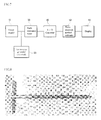
- Fig. 7 is a block diagram of an apparatus for measuring a specific soil resistance for distribution through three electrodes according to an embodiment of the present invention
- Fig. 8 shows a screw type grounded electrode of Fig. 7 .
- an apparatus for measuring a specific soil resistance for distribution through three electrodes includes a power supply 10; a screw-type grounded electrode 20 which receives the power from the power supply 10 and is used in estimating the specific soil resistance by a three-electrode method; an earth resistance tester 30 which measures the earth resistance of the screw-type grounded electrode 20; an analog to digital (A/D) converter 40 which converts an analog earth resistance measured by the earth resistance tester 30 into a digital signal; a three-electrode method estimator 50 which uses the three-electrode method to estimate the specific soil resistance based on the earth resistance converted by the A/D converter 40; and a display 60 which displays the specific soil resistance estimated by the three-electrode method estimator 50.
- the screw-type grounded electrode 20 is made of carbon steel for machine structural use.
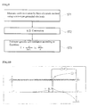
- Fig. 9 is a flowchart of a method for measuring the specific soil resistance for distribution through three electrodes according to an embodiment of the present invention.
- a method of measuring the specific soil resistance includes: measuring an earth resistance value through the screw-type grounded electrode 20 based on the three-electrode method in operation ST1; converting a signal of the analog earth resistance value measured in operation ST1 into a signal of a digital earth resistance value, in operation ST2; and estimating the specific soil resistance in operation ST3 by the three-electrode method based on the signal of the digital earth resistance value converted in operation ST2.
- R is an earth resistance ( ⁇ )
- ⁇ is a specific soil resistance ( ⁇ m)
- L is a length (m) of the screw-type grounded electrode 20
- d is a diameter (m) of the screw-type grounded electrode 20.
- the apparatus according to the invention measures the specific soil resistance as well as the earth resistance by only the three-electrode method.
- Fig. 10 is a view of measuring the specific soil resistance according to one embodiment of the present invention.
- the screw-type grounded electrode 20 was manufactured in a screw shape to be easily embedded in the earth and used repeatedly, and made of SM45C as defined in KSD 3752 (carbon steel for machine structural use).
- the specific soil resistances from respective grounded electrodes were compared with each other and analyzed by embedding a screw-type rod and a copper-type rod in the earth, followed by inversely estimating the specific soil resistance through a general earth-resistance measurement expression with an earth resistance measured by an earth tester.
- a combined tester capable of measuring the specific soil resistance was developed by incorporating an inverse estimation function into an existing digital earth tester.
- the standards of the screw-type grounded electrode 20 are as follows.
- R ⁇ 2 ⁇ ⁇ L ln 4 ⁇ L d
- R is an earth resistance ( ⁇ )
- p is a specific soil resistance ( ⁇ m)
- L is a length (m) of the screw-type grounded electrode 20
- d is a diameter (m) of the screw-type grounded electrode 20.
- Expression 2 can be changed into Expression 3 with respect to the specific soil resistance.
- ⁇ 2 ⁇ ⁇ L R ln ⁇ 4 ⁇ L d
- the specific soil resistance can be calculated by Equation 4.
- Expression 4 was expressed in the case of 350 ⁇ .
- Fig. 11 is a table of inversely calculating the specific soil resistance using a three-electrode method according to an embodiment of the present invention.
- Fig. 11 shows the specific soil resistances which are inversely calculated in the case of 350 ⁇ , 400 ⁇ and 280 ⁇ , respectively.
- the specific soil resistance estimated by the three-electrode method using the screw-type grounded electrode, the specific soil resistance obtained by the general earth-resistance measurement expression, and the specific soil resistance obtained by the conventional four-electrode method are compared and analyzed as follows.
- the specific soil resistance is estimated by the three-electrode method using a general ground copper rod for distribution.
- the specific soil resistance is obtained as in Expression 3.
- Fig. 12 is a comparative table showing actual measurements obtained using an inventive screw-type electrode, a conventional copper-type rod, and a conventional four-electrode method.
- the specific soil resistance with regard to a unit of a target ground rod approximately reaches a mean value of the screw-type or general copper-type measurement.
- Fig. 13 is a comparative table of the specific soil resistances in Fig. 12 .
- the present invention uses the three-electrode method to measure the specific soil resistance as well as the earth resistance in specific soil resistance measurement that is the most basic but likely to be overlooked in a practical distribution work.
- the apparatus and method for three-pole type specific soil resistance measurement for distribution grounding uses three electrodes, thereby providing an effect of measuring the specific soil resistance as well as an earth resistance in the specific soil resistance measurement that is the most basic but likely to be overlooked in a practical distribution work.
- the electrodes are manufactured in the form of a screw-type rod so as to be reused as a grounded electrode, and an inverse-estimation algorithm is embedded in a digital earth tester to be used as a tester for measuring both the earth resistance and the specific soil resistance.
- the apparatus has advantages in view of easy and efficient operability resulting from a combined function of measuring the earth resistance and the specific soil resistance and a portable structure, and can be directly used to enhance the quality of distribution design and/or construction.
Landscapes
- Physics & Mathematics (AREA)
- General Physics & Mathematics (AREA)
- Measurement Of Resistance Or Impedance (AREA)
- Investigating Or Analyzing Materials By The Use Of Electric Means (AREA)
Abstract
Disclosed herein is an apparatus and method for measuring a specific soil resistance for distribution grounding by a three-electrode method. The apparatus uses three electrodes to measure a specific soil resistance as well as an earth resistance based on a three-electrode method in specific soil resistance measurement that is the most basic but likely to be overlooked in a practical distribution work.
Description
- The present invention relates to specific soil resistance measurement, and, more particularly, to an apparatus and method for measuring a specific soil resistance for distribution grounding, which uses three electrodes to measure the specific soil resistance as well as an earth resistance based on a three-electrode method in specific soil resistance measurement that is the most basic but likely to be overlooked in a practical distribution work.
- In general, as a method for measuring a specific soil resistance when constructing a design of a substation grounding, a tower grounding, or similar power transmission work, a four-electrode method proposed by Wenner in 1915 has been used.
- However, since this method uses four or more electrodes (e.g., five electrodes), it is inconvenient to operate measurement instruments, and values obtained by repetitive measurements must be averaged. Further, since the specific soil resistance can vary depending on a gap between the electrodes, the four-electrode method does not ensure an advantageous measurement of the specific soil resistance. Also, the four-electrode method is inadequate for a design of distribution work using a ground rod as a unit. However, an apparatus for measuring a specific soil resistance for distribution according to this invention has an advantage in that it facilitates measurement of the specific soil resistance at a point where the ground rod is buried.
- The four-electrode method used for the grounding work relating to power transmission systems measures the specific soil resistance of a large area, such as the substation grounding, the tower grounding, and the like, several times and obtains an average of the measured resistances. However, since the distribution work is sporadically and widely carried out in a very small region associated with installation of a ground rod, the four-electrode method is inconvenient and thus rarely utilized.
-
Fig. 1 is a view of a conventional four-electrode method for measuring the specific soil resistance. - Here, c1 ∼ c2 are power connections; p1 ∼ p2 are potential difference measurements; 1 is a length of a grounded electrode; a is a distance between the grounded electrodes; V is a voltage; and I is a current.
- Wenner's four-electrode method is a method of arranging four electrodes at regular intervals in a straight line, which was published by Frank Wenner in 1915 and is the most frequently used method for measuring the specific soil resistance.
- As shown in
Fig. 1 , four electrodes are installed in the earth, and a current I flowing in opposite outer-electrodes, and a voltage V induced between two inner-electrodes are measured to thereby calculate soil resistivity. Power is supplied between two outer grounded electrodes c1 and c2 to cause current to flow through the earth, and, at this time, a potential difference between the two inner grounded electrodes p1 and p2 is measured to obtain an earth resistance R (Ω ) from V/I. Further, if a distance between the electrodes is a [m], a soil resistivity p (Ω .m) is calculated byExpression 1.
Expression 1 represents a mean soil resistivity of soil at an approximate depth of (0.75 ∼ 1)a. - The soil resistivity is calculated regardless of the test voltage, current, and earth resistances at c1, c2, p1, and p2. If the distance "a" between the electrodes is large, the mean soil resistivity is measured at a depth as deep as the test current reaches. If a water pipe, a gas pipe or similar metal pipe is buried under the ground, the test current may be bypassed via such a conductive metal so that an error may occur. Therefore, to correctly measure the soil resistivity through the four-electrode method, it is desirable that the soil resistivity be measured many times and averaged while changing the arranging direction and the intervals of the four electrodes.
-
Fig. 2 is a graph depicting a general correlation between a specific resistance (ρ ) and a distance (a) between the electrodes. As shown inFig. 2 , the specific soil resistance may vary depending on the intervals between the electrodes c1 ∼ c2. -
Fig. 3 is a table showing specific soil resistances according to General Design Standard 2601;Fig. 4 is a table showing specific soil resistances according to a general distribution practice textbook;Fig. 5 is a table showing specific soil resistances according to a handbook of technical terminology (in the field of power transmission); andFig. 6 is a table showing specific soil resistances according to Japan Electrical Construction Association ("Soil resistivity and Earth resistance," July 1992). - Referring to
Figs. 3 to 6 , the specific soil resistances according to design standards are statistic values according to the kinds of soils, in which variation of the values is too large to be applied by a distribution designer. - There is no method other than the method of burying many electrodes under the ground and using a tester to measure the specific soil resistance.
- However, since the conventional four-electrode method uses four or more electrodes, there are problems in that wiring is inconvenient and measurements are repeated many times. Further, although this method is adequate for a large area, the wiring work needs a smaller unit instrument for the grounding design and construction than that of the power transmission work, and is scattered at many points. Therefore, there is a need for a portable and convenient tester for measuring the specific soil resistance at a unit point where the ground rod is buried.
- The present invention is conceived to solve the problems of the conventional techniques as described above, and an aspect of the present invention is to provide an apparatus for three-pole type specific soil resistance measurement for distribution grounding that uses three electrodes to measure a specific soil resistance as well as an earth resistance based on a three-electrode method in specific soil resistance measurement which is the most basic but likely to be overlooked in a practical distribution work.
- In accordance with an aspect of the present invention, an apparatus for measuring a specific soil resistance for distribution through three electrodes includes: a power supply; a screw-type grounded electrode configured to receive power from the power supply and used in estimating the specific soil resistance by a three-electrode method; an earth resistance tester configured to measure an earth resistance of the screw-type grounded electrode; an A/D converter configured to convert an analog signal of an earth resistance measured by the earth resistance tester into a digital signal; a three-electrode method estimator configured to estimate the specific soil resistance using the three-electrode method based on the earth resistance converted by the A/D converter; and a display configured to display the specific soil resistance estimated by the three-electrode method estimator.
- In accordance with another aspect of the present invention, a method of measuring a specific soil resistance for distribution through three electrodes includes: measuring an earth resistance value through a screw-type grounded electrode based on a three-electrode method; converting a signal of the measured analog earth resistance value into a signal of a digital earth resistance value; and estimating the specific soil resistance by the three-electrode method based on the converted signal of the digital earth resistance value.
- The above and other aspects, features and advantages of the present invention will become apparent from the following description of exemplary embodiments given in conjunction with the accompanying drawings, in which:
-
Fig. 1 is a view of a conventional four-electrode method for measuring a specific soil resistance; -
Fig. 2 is a graph depicting a general correlation between a specific resistance (ρ ) and a distance (a) between electrodes; -
Fig. 3 is a table showing specific soil resistances according to General Design Standard 2601; -
Fig. 4 is a table showing specific soil resistances according to a general distribution practice textbook; -
Fig. 5 is a table showing specific soil resistances according to a handbook of technical terminology (in the field of power transmission); -
Fig. 6 is a table showing specific soil resistances according to Japan Electrical Construction Association ("Soil Resistivity and Earth Resistance," July 1992); -
Fig. 7 is a block diagram of an apparatus which measures a specific soil resistance for distribution through three electrodes according to an embodiment of the present invention; -
Fig. 8 shows a screw type grounded electrode ofFig. 7 ; -
Fig. 9 is a flowchart of a method for measuring the specific soil resistance for distribution through three electrodes according to an embodiment of the present invention; -
Fig. 10 is a view of measuring the specific soil resistance according to an embodiment of the present invention; -
Fig. 11 is a table showing inversely calculated specific soil resistances by a three-electrode method according to an embodiment of the present invention; -
Fig. 12 is a comparative table showing actual measurements obtained using an inventive screw-type electrode, a conventional copper-type rod, and a conventional four-electrode method; and -
Fig. 13 is a comparative table of the specific soil resistances inFig. 12 . - Hereinafter, exemplary embodiments of the present invention will be described with reference to accompanying drawings.
-
Fig. 7 is a block diagram of an apparatus for measuring a specific soil resistance for distribution through three electrodes according to an embodiment of the present invention, andFig. 8 shows a screw type grounded electrode ofFig. 7 . - As shown therein, an apparatus for measuring a specific soil resistance for distribution through three electrodes according to an embodiment of the present invention includes a
power supply 10; a screw-type groundedelectrode 20 which receives the power from thepower supply 10 and is used in estimating the specific soil resistance by a three-electrode method; anearth resistance tester 30 which measures the earth resistance of the screw-type groundedelectrode 20; an analog to digital (A/D)converter 40 which converts an analog earth resistance measured by theearth resistance tester 30 into a digital signal; a three-electrode method estimator 50 which uses the three-electrode method to estimate the specific soil resistance based on the earth resistance converted by the A/D converter 40; and adisplay 60 which displays the specific soil resistance estimated by the three-electrode method estimator 50. - In this embodiment, the screw-type grounded
electrode 20 is made of carbon steel for machine structural use. - The three-
electrode method estimator 50 estimates the specific soil resistance based on the following expression:
electrode 20, and d is a diameter (m) of the screw-type groundedelectrode 20. -
Fig. 9 is a flowchart of a method for measuring the specific soil resistance for distribution through three electrodes according to an embodiment of the present invention. - As shown therein, a method of measuring the specific soil resistance includes: measuring an earth resistance value through the screw-type grounded
electrode 20 based on the three-electrode method in operation ST1; converting a signal of the analog earth resistance value measured in operation ST1 into a signal of a digital earth resistance value, in operation ST2; and estimating the specific soil resistance in operation ST3 by the three-electrode method based on the signal of the digital earth resistance value converted in operation ST2. - In this embodiment, the specific soil resistance is estimated in operation ST3 by the following expression:

electrode 20, and d is a diameter (m) of the screw-type groundedelectrode 20. - With this configuration, the apparatus and the method for measuring the specific soil resistance through the three electrodes according to the present invention will be described as follows.
- Herein, a detailed description of publicly known functions or configurations will be omitted for clarity so as not to unnecessarily obscure the subject matter of the invention. Further, the following terms are defined in consideration of functions of the present invention, which can be changed according to users, intention of an operator, a judicial precedent, etc., and should be understood based on the overall disclosure in this specification.
- First, the apparatus according to the invention measures the specific soil resistance as well as the earth resistance by only the three-electrode method.
-
Fig. 10 is a view of measuring the specific soil resistance according to one embodiment of the present invention. - According to this embodiment, the screw-type grounded
electrode 20 was manufactured in a screw shape to be easily embedded in the earth and used repeatedly, and made of SM45C as defined in KSD 3752 (carbon steel for machine structural use). Second, the specific soil resistances from respective grounded electrodes were compared with each other and analyzed by embedding a screw-type rod and a copper-type rod in the earth, followed by inversely estimating the specific soil resistance through a general earth-resistance measurement expression with an earth resistance measured by an earth tester. Third, a combined tester capable of measuring the specific soil resistance was developed by incorporating an inverse estimation function into an existing digital earth tester. - The standards of the screw-type grounded
electrode 20 are as follows. - 1) Straight length to a screw end point : 430mm
- 2) Screw creepage-length: 1,401 mm
- 3) Outer diameter of screw: 25mm
- 4) Inner diameter of screw: 12.5mm
- 5) Cross-sectional area of screw: 55,030mm2 (= 2π * R * h = 2π * R * 430)
- 6) Converted diameter: 40.736mm (straight length and cross-sectional area are constant)(=55,030/2π * R * 430)
- Further, inverse calculation of the specific soil resistance using the three-electrode method is based on
Expression 2.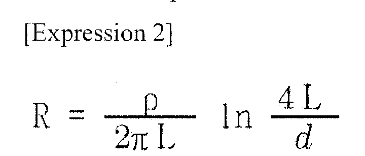
electrode 20, and d is a diameter (m) of the screw-type groundedelectrode 20. -
Expression 2 can be changed intoExpression 3 with respect to the specific soil resistance.
- For example, if the ground rod (11000*ψ 14) is embedded within a construction site and 350Ω , 400Ω and 280Ω are measured, the specific soil resistance can be calculated by
Equation 4.
-
Expression 4 was expressed in the case of 350Ω . -
Fig. 11 is a table of inversely calculating the specific soil resistance using a three-electrode method according to an embodiment of the present invention.Fig. 11 shows the specific soil resistances which are inversely calculated in the case of 350Ω, 400Ω and 280Ω, respectively. - Meanwhile, the specific soil resistance estimated by the three-electrode method using the screw-type grounded electrode, the specific soil resistance obtained by the general earth-resistance measurement expression, and the specific soil resistance obtained by the conventional four-electrode method are compared and analyzed as follows.
- First, in the case of using a general earth-resistance measurement expression,
- The specific soil resistance is estimated by the three-electrode method using a general ground copper rod for distribution.
- The ground copper rod having a size of 14 φ and 1,000 mm was sunk to a depth of only 700mm, so that it can be installed and removed repeatedly for measurement. Here, 1 = 0.7 [m], d = 0.014 [m]
- Tester model: digital earth tester TK-2040
- Specific soil resistance: obtained by inversely estimating the earth resistance through the general earth resistance expression.
- Second, in the case of using the conventional four-electrode method,
- Tester model: earth insulator tester (MI-2088) of METREL Horjul
- Specific soil resistance: obtained by direct measurement based on the four-electrode method (Wenner's four-electrode method)
- Third, in the case of using the three-electrode method with the screw-type grounded electrode to estimate the specific soil resistance,
- The rod manufactured in a screw shape and having a size of 40.736φ and 430 mm (converted diameter and straight length) was used. Here, 1 = 0.43 [m], d = 0.040736 [m].
- Tester model: digital earth tester TK-2040
- Specific soil resistance: obtained by inversely estimating the earth resistance through the general earth resistance expression.
- The specific soil resistance is obtained as in
Expression 3. -
Fig. 12 is a comparative table showing actual measurements obtained using an inventive screw-type electrode, a conventional copper-type rod, and a conventional four-electrode method. - Results from comparing the specific soil resistance tester for distribution with the ground copper rod are shown in
Fig. 12 . However, the measurement based on the four-electrode method is provided merely for reference since this method is not applied to a small area where the ground rod is regarded as a unit. - Thus, based on results from analyzing the actual measurement, a measurement correlation between the inventive screw-type and the general copper rod is 0.8 as shown in
Expression 5.
- Further, as can be understood from the table shown in
Fig. 12 , the specific soil resistance with regard to a unit of a target ground rod approximately reaches a mean value of the screw-type or general copper-type measurement. -
Fig. 13 is a comparative table of the specific soil resistances inFig. 12 . - As such, the present invention uses the three-electrode method to measure the specific soil resistance as well as the earth resistance in specific soil resistance measurement that is the most basic but likely to be overlooked in a practical distribution work.
- As apparent from the foregoing description, the apparatus and method for three-pole type specific soil resistance measurement for distribution grounding according to the present invention uses three electrodes, thereby providing an effect of measuring the specific soil resistance as well as an earth resistance in the specific soil resistance measurement that is the most basic but likely to be overlooked in a practical distribution work.
- In development of the apparatus (three electrodes) for measuring the specific soil resistance for distribution, the electrodes are manufactured in the form of a screw-type rod so as to be reused as a grounded electrode, and an inverse-estimation algorithm is embedded in a digital earth tester to be used as a tester for measuring both the earth resistance and the specific soil resistance.
- According to the present invention, the apparatus has advantages in view of easy and efficient operability resulting from a combined function of measuring the earth resistance and the specific soil resistance and a portable structure, and can be directly used to enhance the quality of distribution design and/or construction.
- Although the present invention has been described with reference to the embodiments and the accompanying drawings, it should be be apparent to those skilled in the art that the embodiments are given by way of illustration and that various modifications and equivalent embodiments can be made without departing from the spirit and scope of the present invention, as defined only by the accompanying claims.
Claims (5)
- An apparatus for measuring a specific soil resistance for distribution through three electrodes, comprising:a power supply;a screw-type grounded electrode configured to receive power from the power supply and used in estimating the specific soil resistance by a three-electrode method;an earth resistance tester configured to measure an earth resistance of the screw-type grounded electrode;an A/D converter configured to convert an analog signal of an earth resistance measured by the earth resistance tester into a digital signal;a three-electrode method estimator configured to estimate the specific soil resistance using the three-electrode method based on the earth resistance converted by the A/D converter; anda display configured to display the specific soil resistance estimated by the three-electrode method estimator.
- The apparatus according to claim 1, wherein the screw-type grounded electrode comprises carbon steel for machine structural use.
- The apparatus according to claim 1 or 2, wherein the three-electrode method estimator estimates the specific soil resistance by the following expression:

- A method of measuring a specific soil resistance for distribution through three electrodes, the method comprising:measuring an earth resistance value through a screw-type grounded electrode based on a three-electrode method;converting a signal of the measured analog earth resistance value into a signal of a digital earth resistance value; andestimating the specific soil resistance by the three-electrode method based on the converted signal of the digital earth resistance value.
- The method according to claim 4, wherein the specific soil resistance is estimated by the following expression:

Priority Applications (1)
| Application Number | Priority Date | Filing Date | Title |
|---|---|---|---|
| EP08169622A EP2189799A1 (en) | 2008-11-21 | 2008-11-21 | Apparatus and method for three-pole type measuring of specific soil resistance for distribution grounding |
Applications Claiming Priority (1)
| Application Number | Priority Date | Filing Date | Title |
|---|---|---|---|
| EP08169622A EP2189799A1 (en) | 2008-11-21 | 2008-11-21 | Apparatus and method for three-pole type measuring of specific soil resistance for distribution grounding |
Publications (1)
| Publication Number | Publication Date |
|---|---|
| EP2189799A1 true EP2189799A1 (en) | 2010-05-26 |
Family
ID=40547780
Family Applications (1)
| Application Number | Title | Priority Date | Filing Date |
|---|---|---|---|
| EP08169622A Withdrawn EP2189799A1 (en) | 2008-11-21 | 2008-11-21 | Apparatus and method for three-pole type measuring of specific soil resistance for distribution grounding |
Country Status (1)
| Country | Link |
|---|---|
| EP (1) | EP2189799A1 (en) |
Cited By (8)
| Publication number | Priority date | Publication date | Assignee | Title |
|---|---|---|---|---|
| DE202011050790U1 (en) | 2011-07-22 | 2012-07-09 | Uwe Bröhl | Device and measuring arrangement for determining the specific earth resistance |
| CN103941095A (en) * | 2014-05-13 | 2014-07-23 | 尚兵 | Method for testing electrical resistivity of earth around underground metallic conduit |
| JP2014153324A (en) * | 2013-02-13 | 2014-08-25 | East Japan Railway Co | Measuring method and measuring device of ground resistance |
| CN104502726A (en) * | 2014-12-01 | 2015-04-08 | 国网辽宁省电力有限公司锦州供电公司 | Method for measuring the power-frequency grounding resistance of tower and cement pole |
| CN105425049A (en) * | 2015-10-29 | 2016-03-23 | 国网浙江省电力公司台州供电公司 | A method of testing the grounding resistance of the earth grid |
| CN105823932A (en) * | 2016-03-11 | 2016-08-03 | 成都信息工程大学 | Grounding resistance testing method for frozen earth and snow-covered environments |
| US11061079B2 (en) | 2017-02-04 | 2021-07-13 | Shanxi Quan'an New Technology Development Co., Ltd. | Grounding monitoring system, method, device and computer readable storage medium |
| CN120928042A (en) * | 2025-09-09 | 2025-11-11 | 西安合电电气有限公司 | On-line monitoring method and system for grounding resistance, storage medium and electronic equipment |
Citations (6)
| Publication number | Priority date | Publication date | Assignee | Title |
|---|---|---|---|---|
| US4209741A (en) * | 1978-03-08 | 1980-06-24 | The United States Of America As Represented By The Secretary Of The Interior | Apparatus for the continuous monitoring of ground bed resistance |
| FR2668138A1 (en) * | 1990-10-19 | 1992-04-24 | Electricite De France | Apparatus for unreeling or rewinding one or more wires of great length and application to the measurement of earth-connection resistance |
| WO1993019379A1 (en) * | 1992-03-19 | 1993-09-30 | Electronic Development, Inc. | Apparatus and method for measuring ground to earth impedance |
| JPH112650A (en) * | 1997-06-13 | 1999-01-06 | Nippon Telegr & Teleph Corp <Ntt> | Ground resistance measuring device and measuring method thereof |
| EP1239292A2 (en) * | 2001-03-08 | 2002-09-11 | Lem Norma GmbH | Device for the measurement of the resistance to ground |
| WO2006115380A1 (en) * | 2005-04-27 | 2006-11-02 | Electronics And Telecommunications Research Institute | Method of detecting soil structure using voltage slope and measuring earth resistance |
-
2008
- 2008-11-21 EP EP08169622A patent/EP2189799A1/en not_active Withdrawn
Patent Citations (6)
| Publication number | Priority date | Publication date | Assignee | Title |
|---|---|---|---|---|
| US4209741A (en) * | 1978-03-08 | 1980-06-24 | The United States Of America As Represented By The Secretary Of The Interior | Apparatus for the continuous monitoring of ground bed resistance |
| FR2668138A1 (en) * | 1990-10-19 | 1992-04-24 | Electricite De France | Apparatus for unreeling or rewinding one or more wires of great length and application to the measurement of earth-connection resistance |
| WO1993019379A1 (en) * | 1992-03-19 | 1993-09-30 | Electronic Development, Inc. | Apparatus and method for measuring ground to earth impedance |
| JPH112650A (en) * | 1997-06-13 | 1999-01-06 | Nippon Telegr & Teleph Corp <Ntt> | Ground resistance measuring device and measuring method thereof |
| EP1239292A2 (en) * | 2001-03-08 | 2002-09-11 | Lem Norma GmbH | Device for the measurement of the resistance to ground |
| WO2006115380A1 (en) * | 2005-04-27 | 2006-11-02 | Electronics And Telecommunications Research Institute | Method of detecting soil structure using voltage slope and measuring earth resistance |
Non-Patent Citations (7)
| Title |
|---|
| CHEN Y ET AL: "Correlation between laboratory and field tests on the impulse impedance of rod-type ground electrodes", IEE PROCEEDINGS: GENERATION, TRANSMISSION AND DISTRIBUTION, INSTITUTION OF ELECTRICAL ENGINEERS, GB, vol. 150, no. 4, 14 July 2003 (2003-07-14), pages 420 - 426, XP006020476, ISSN: 1350-2360 * |
| CLARK R J ET AL: "Some Chemical Treatments to Reduce the Resistance of Ground Connections", IEEE TRANSACTIONS ON POWER APPARATUS AND SYSTEMS, IEEE INC. NEW YORK, US, vol. 71, no. 3, 1 April 1960 (1960-04-01), pages 1016 - 1023, XP011210758, ISSN: 0018-9510 * |
| MICHAELS K M: "Earth ground resistance testing for low voltage power systems", INDUSTRIAL AND COMMERCIAL POWER SYSTEMS TECHNICAL CONFERENCE, 1994. CO NFERENCE RECORD, PAPERS PRESENTED AT THE 1994 ANNUAL MEETING, 1994 IEE E IRVINE, CA, USA 1-5 MAY 1994, NEW YORK, NY, USA,IEEE, 1 May 1994 (1994-05-01), pages 143 - 151, XP010121699, ISBN: 978-0-7803-1877-9 * |
| RUAN W ET AL: "Perfonnance of HVDC ground electrode in various soil structures", POWER SYSTEM TECHNOLOGY, 2002. PROCEEDINGS. POWERCON 2002. INTERNATION AL CONFERENCE ON, PISCATAWAY, NJ, USA,IEEE, vol. 2, 13 October 2002 (2002-10-13), pages 962 - 968, XP010614898, ISBN: 978-0-7803-7459-1 * |
| SOIL RESISTIVITY AND EARTH RESISTANCE, July 1992 (1992-07-01) |
| TAKAGI S ET AL: "A new method of measuring earth resistance by using the three-electrode method in which the grounding conductor is not disconnected from the earth electrode", TELECOMMUNICATIONS ENERGY CONFERENCE, 2000. INTELEC. TWENTY-SECOND INT ERNATIONAL SEPTEMBER 10-14, 2000, PISCATAWAY, NJ, USA,IEEE, 10 September 2000 (2000-09-10), pages 659 - 664, XP010523256, ISBN: 978-0-7803-6407-3 * |
| ZIPSE D W ED - ANONYMOUS: "Earthing - grounding methods: a primer", INDUSTRIAL AND COMMERICAL POWER SYSTEMS TECHNICAL CONFERENCE, 2002. 20 02 IEEE, IEEE, PI, 1 January 2002 (2002-01-01), pages 158 - 177, XP031098497, ISBN: 978-0-7803-7483-6 * |
Cited By (10)
| Publication number | Priority date | Publication date | Assignee | Title |
|---|---|---|---|---|
| DE202011050790U1 (en) | 2011-07-22 | 2012-07-09 | Uwe Bröhl | Device and measuring arrangement for determining the specific earth resistance |
| JP2014153324A (en) * | 2013-02-13 | 2014-08-25 | East Japan Railway Co | Measuring method and measuring device of ground resistance |
| CN103941095A (en) * | 2014-05-13 | 2014-07-23 | 尚兵 | Method for testing electrical resistivity of earth around underground metallic conduit |
| CN103941095B (en) * | 2014-05-13 | 2016-05-04 | 尹春峰 | A kind of method that the resistivity of underground metallic conduit surrounding soil is tested |
| CN104502726A (en) * | 2014-12-01 | 2015-04-08 | 国网辽宁省电力有限公司锦州供电公司 | Method for measuring the power-frequency grounding resistance of tower and cement pole |
| CN105425049A (en) * | 2015-10-29 | 2016-03-23 | 国网浙江省电力公司台州供电公司 | A method of testing the grounding resistance of the earth grid |
| CN105823932A (en) * | 2016-03-11 | 2016-08-03 | 成都信息工程大学 | Grounding resistance testing method for frozen earth and snow-covered environments |
| US11061079B2 (en) | 2017-02-04 | 2021-07-13 | Shanxi Quan'an New Technology Development Co., Ltd. | Grounding monitoring system, method, device and computer readable storage medium |
| CN120928042A (en) * | 2025-09-09 | 2025-11-11 | 西安合电电气有限公司 | On-line monitoring method and system for grounding resistance, storage medium and electronic equipment |
| CN120928042B (en) * | 2025-09-09 | 2026-02-06 | 西安合电电气有限公司 | Methods, systems, storage media and electronic equipment for online monitoring of grounding resistance |
Similar Documents
| Publication | Publication Date | Title |
|---|---|---|
| US8310251B2 (en) | System for assessing pipeline condition | |
| CN112430817B (en) | Buried metal pipeline corrosion parameter test probe split device and test method | |
| JPH10332622A (en) | Method and apparatus for determining state of cathodic protection using steel probe | |
| US20100134114A1 (en) | Apparatus and Method for Three-Pole Type Measuring Specific Soil Resistance Measurement for Distribution Grounding | |
| EP1223631A3 (en) | Arrangement and method for determining the electroconductivity of a coolant in a fuel cell stack by differential voltage measurements | |
| CN106896299A (en) | Test method for insulation performance of pipeline insulation devices | |
| JP2010266342A (en) | Metal corrosion diagnosis method | |
| JP2010127851A (en) | Apparatus and method for measuring earth resistivity for use in power distribution using three electrodes | |
| KR100870061B1 (en) | Electric resistivity monitoring electrode and side line designed using it | |
| CN115420791B (en) | A method, system and device for detecting corrosion of macro cells in power transmission and transformation grounding grid | |
| KR20090032380A (en) | Apparatus for measuring high dielectric constant resistance for distribution using 3-electrode and its method | |
| JP2005091191A (en) | Method for detecting coating defects in buried metal pipes | |
| CN101750543A (en) | Ground inherent resistance measuring device using three electrodes for power distribution and method thereof | |
| KR101127071B1 (en) | Device and method for measuring | |
| CN108872321B (en) | Moisture content measuring device based on plug-in conductivity sensor | |
| KR100508877B1 (en) | method for detecting the coating defect and corrosion points of the pipelines in soil using the electrochemical impedance spectroscopy | |
| CN113791028B (en) | A detection device and method for directly detecting soil corrosion rate of metal materials | |
| JP3177049B2 (en) | Corrosion protection potential estimation method | |
| RU2626609C1 (en) | Method of estimating technical condition of insulating coating of underground pipeline | |
| JPH0423748B2 (en) | ||
| Zhang et al. | Development of an electrochemical in situ detection sensor for grounding grid corrosion | |
| CN107490725A (en) | The pole method of testing of special industry place grounding resistance three | |
| CN112014618B (en) | Contact voltage detection device, grounding system and contact voltage detection method | |
| JP3084154B2 (en) | Estimation method of anticorrosion potential of buried pipe | |
| CN112014619A (en) | Step voltage detection device, grounding system and step voltage detection method |
Legal Events
| Date | Code | Title | Description |
|---|---|---|---|
| PUAI | Public reference made under article 153(3) epc to a published international application that has entered the european phase |
Free format text: ORIGINAL CODE: 0009012 |
|
| AK | Designated contracting states |
Kind code of ref document: A1 Designated state(s): AT BE BG CH CY CZ DE DK EE ES FI FR GB GR HR HU IE IS IT LI LT LU LV MC MT NL NO PL PT RO SE SI SK TR |
|
| AX | Request for extension of the european patent |
Extension state: AL BA MK RS |
|
| AKY | No designation fees paid | ||
| REG | Reference to a national code |
Ref country code: DE Ref legal event code: 8566 |
|
| STAA | Information on the status of an ep patent application or granted ep patent |
Free format text: STATUS: THE APPLICATION IS DEEMED TO BE WITHDRAWN |
|
| 18D | Application deemed to be withdrawn |
Effective date: 20101127 |