EP2189699A1 - Duplex pipe fitting, exclusive tool for the duplex pipe fitting, refrigeration system employing the duplex pipe fitting, and separation type air conditioner - Google Patents
Duplex pipe fitting, exclusive tool for the duplex pipe fitting, refrigeration system employing the duplex pipe fitting, and separation type air conditioner Download PDFInfo
- Publication number
- EP2189699A1 EP2189699A1 EP08829965A EP08829965A EP2189699A1 EP 2189699 A1 EP2189699 A1 EP 2189699A1 EP 08829965 A EP08829965 A EP 08829965A EP 08829965 A EP08829965 A EP 08829965A EP 2189699 A1 EP2189699 A1 EP 2189699A1
- Authority
- EP
- European Patent Office
- Prior art keywords
- pipe
- main body
- coupling member
- fitting
- fitting main
- Prior art date
- Legal status (The legal status is an assumption and is not a legal conclusion. Google has not performed a legal analysis and makes no representation as to the accuracy of the status listed.)
- Granted
Links
Images






Classifications
-
- B—PERFORMING OPERATIONS; TRANSPORTING
- B25—HAND TOOLS; PORTABLE POWER-DRIVEN TOOLS; MANIPULATORS
- B25B—TOOLS OR BENCH DEVICES NOT OTHERWISE PROVIDED FOR, FOR FASTENING, CONNECTING, DISENGAGING, OR HOLDING
- B25B13/00—Spanners; Wrenches
- B25B13/48—Spanners; Wrenches for special purposes
-
- B—PERFORMING OPERATIONS; TRANSPORTING
- B25—HAND TOOLS; PORTABLE POWER-DRIVEN TOOLS; MANIPULATORS
- B25B—TOOLS OR BENCH DEVICES NOT OTHERWISE PROVIDED FOR, FOR FASTENING, CONNECTING, DISENGAGING, OR HOLDING
- B25B13/00—Spanners; Wrenches
- B25B13/02—Spanners; Wrenches with rigid jaws
-
- F—MECHANICAL ENGINEERING; LIGHTING; HEATING; WEAPONS; BLASTING
- F16—ENGINEERING ELEMENTS AND UNITS; GENERAL MEASURES FOR PRODUCING AND MAINTAINING EFFECTIVE FUNCTIONING OF MACHINES OR INSTALLATIONS; THERMAL INSULATION IN GENERAL
- F16L—PIPES; JOINTS OR FITTINGS FOR PIPES; SUPPORTS FOR PIPES, CABLES OR PROTECTIVE TUBING; MEANS FOR THERMAL INSULATION IN GENERAL
- F16L19/00—Joints in which sealing surfaces are pressed together by means of a member, e.g. a swivel nut, screwed on, or into, one of the joint parts
-
- F—MECHANICAL ENGINEERING; LIGHTING; HEATING; WEAPONS; BLASTING
- F16—ENGINEERING ELEMENTS AND UNITS; GENERAL MEASURES FOR PRODUCING AND MAINTAINING EFFECTIVE FUNCTIONING OF MACHINES OR INSTALLATIONS; THERMAL INSULATION IN GENERAL
- F16L—PIPES; JOINTS OR FITTINGS FOR PIPES; SUPPORTS FOR PIPES, CABLES OR PROTECTIVE TUBING; MEANS FOR THERMAL INSULATION IN GENERAL
- F16L19/00—Joints in which sealing surfaces are pressed together by means of a member, e.g. a swivel nut, screwed on, or into, one of the joint parts
- F16L19/04—Joints in which sealing surfaces are pressed together by means of a member, e.g. a swivel nut, screwed on, or into, one of the joint parts using additional rigid rings, sealing directly on at least one pipe end, which is flared either before or during the making of the connection
-
- F—MECHANICAL ENGINEERING; LIGHTING; HEATING; WEAPONS; BLASTING
- F16—ENGINEERING ELEMENTS AND UNITS; GENERAL MEASURES FOR PRODUCING AND MAINTAINING EFFECTIVE FUNCTIONING OF MACHINES OR INSTALLATIONS; THERMAL INSULATION IN GENERAL
- F16L—PIPES; JOINTS OR FITTINGS FOR PIPES; SUPPORTS FOR PIPES, CABLES OR PROTECTIVE TUBING; MEANS FOR THERMAL INSULATION IN GENERAL
- F16L19/00—Joints in which sealing surfaces are pressed together by means of a member, e.g. a swivel nut, screwed on, or into, one of the joint parts
- F16L19/08—Joints in which sealing surfaces are pressed together by means of a member, e.g. a swivel nut, screwed on, or into, one of the joint parts with metal rings which bite into the wall of the pipe
- F16L19/10—Joints in which sealing surfaces are pressed together by means of a member, e.g. a swivel nut, screwed on, or into, one of the joint parts with metal rings which bite into the wall of the pipe the profile of the ring being altered
-
- F—MECHANICAL ENGINEERING; LIGHTING; HEATING; WEAPONS; BLASTING
- F16—ENGINEERING ELEMENTS AND UNITS; GENERAL MEASURES FOR PRODUCING AND MAINTAINING EFFECTIVE FUNCTIONING OF MACHINES OR INSTALLATIONS; THERMAL INSULATION IN GENERAL
- F16L—PIPES; JOINTS OR FITTINGS FOR PIPES; SUPPORTS FOR PIPES, CABLES OR PROTECTIVE TUBING; MEANS FOR THERMAL INSULATION IN GENERAL
- F16L19/00—Joints in which sealing surfaces are pressed together by means of a member, e.g. a swivel nut, screwed on, or into, one of the joint parts
- F16L19/08—Joints in which sealing surfaces are pressed together by means of a member, e.g. a swivel nut, screwed on, or into, one of the joint parts with metal rings which bite into the wall of the pipe
- F16L19/10—Joints in which sealing surfaces are pressed together by means of a member, e.g. a swivel nut, screwed on, or into, one of the joint parts with metal rings which bite into the wall of the pipe the profile of the ring being altered
- F16L19/103—Joints in which sealing surfaces are pressed together by means of a member, e.g. a swivel nut, screwed on, or into, one of the joint parts with metal rings which bite into the wall of the pipe the profile of the ring being altered with more than one ring per pipe end being used
-
- F—MECHANICAL ENGINEERING; LIGHTING; HEATING; WEAPONS; BLASTING
- F16—ENGINEERING ELEMENTS AND UNITS; GENERAL MEASURES FOR PRODUCING AND MAINTAINING EFFECTIVE FUNCTIONING OF MACHINES OR INSTALLATIONS; THERMAL INSULATION IN GENERAL
- F16L—PIPES; JOINTS OR FITTINGS FOR PIPES; SUPPORTS FOR PIPES, CABLES OR PROTECTIVE TUBING; MEANS FOR THERMAL INSULATION IN GENERAL
- F16L19/00—Joints in which sealing surfaces are pressed together by means of a member, e.g. a swivel nut, screwed on, or into, one of the joint parts
- F16L19/08—Joints in which sealing surfaces are pressed together by means of a member, e.g. a swivel nut, screwed on, or into, one of the joint parts with metal rings which bite into the wall of the pipe
- F16L19/10—Joints in which sealing surfaces are pressed together by means of a member, e.g. a swivel nut, screwed on, or into, one of the joint parts with metal rings which bite into the wall of the pipe the profile of the ring being altered
- F16L19/14—Joints in which sealing surfaces are pressed together by means of a member, e.g. a swivel nut, screwed on, or into, one of the joint parts with metal rings which bite into the wall of the pipe the profile of the ring being altered the rings being integral with one of the connecting parts
-
- F—MECHANICAL ENGINEERING; LIGHTING; HEATING; WEAPONS; BLASTING
- F25—REFRIGERATION OR COOLING; COMBINED HEATING AND REFRIGERATION SYSTEMS; HEAT PUMP SYSTEMS; MANUFACTURE OR STORAGE OF ICE; LIQUEFACTION SOLIDIFICATION OF GASES
- F25B—REFRIGERATION MACHINES, PLANTS OR SYSTEMS; COMBINED HEATING AND REFRIGERATION SYSTEMS; HEAT PUMP SYSTEMS
- F25B41/00—Fluid-circulation arrangements
- F25B41/40—Fluid line arrangements
-
- Y—GENERAL TAGGING OF NEW TECHNOLOGICAL DEVELOPMENTS; GENERAL TAGGING OF CROSS-SECTIONAL TECHNOLOGIES SPANNING OVER SEVERAL SECTIONS OF THE IPC; TECHNICAL SUBJECTS COVERED BY FORMER USPC CROSS-REFERENCE ART COLLECTIONS [XRACs] AND DIGESTS
- Y10—TECHNICAL SUBJECTS COVERED BY FORMER USPC
- Y10T—TECHNICAL SUBJECTS COVERED BY FORMER US CLASSIFICATION
- Y10T29/00—Metal working
- Y10T29/53—Means to assemble or disassemble
- Y10T29/5367—Coupling to conduit
Definitions
- the present invention relates to a duplex pipe fitting having a thread portion at either end, and more particularly, to a duplex pipe fitting having a connecting structure that cannot be easily disassembled after pipes are connected thereto.
- a simplex pipe fitting As one type of pipe fittings used for fluid pipes through which fluid is passed, a simplex pipe fitting has been known that includes a first end and a second end. The first end has a pipe connecting port, to which a pipe is connected by brazing. The second end has a thread portion, to which a pipe is connected by threading a coupling member (nut), or by through screwing.
- Duplex pipe fittings are also known, which have a thread potion at either end, to which a pipe is connected by threading a coupling member (nut).
- Fig. 13 shows an example of piping for a separation type air conditioner using the latter duplex pipe fitting, which is disclosed in Patent Document 1.
- a pipe 102 is drawn to the outside from an indoor heat exchanger mounted in an indoor unit 101 of a prior art separation type air conditioner, and the distal end of the pipe 102 is connected to a flare type simplex pipe fitting 103.
- the simplex pipe fitting 103 is provided as a connecting portion of the indoor unit 101.
- an outdoor unit 105 has a flare type simplex pipe fitting 106 serving as a connecting portion.
- a first connecting pipe (communication pipe) 104 and a second connecting pipe 107 are connected to the inside and outside connecting portions, and the first connecting pipe 104 and the second connecting pipe 107 are connected to each other at their distal ends.
- Patent Document 2 discloses a specific structure of a duplex pipe fitting in addition to Patent Document 1.
- the duplex pipe fitting disclosed in Patent Document 2 includes a fitting body having a thread portion to be connected to a pipe at either end, two nuts threaded to the thread portion, and sleeves accommodated in the nuts.
- the simplex pipe fittings 103, 106 and the duplex pipe fitting 108 which are used in the above example of piping, are installed by tightening the coupling members (nuts in some cases) with fastening tools.
- the fastening is continuously executed until the tightening torque reaches a value that indicates the completion of fastening.
- the tightening torque reaches the completion indicating value, the fastening is finished, and the pipe connecting is ended.
- the first and second connecting pipes 104, 107 and the pipe fittings 103, 106, 108 are used without being changed.
- a pipe fitting having a structure that cannot be easily loosened is desired.
- a duplex pipe fitting that includes a fitting main body having a pair of first thread portions and a pair of coupling members having second thread portions which are threaded to the respective first thread portions of the fitting main body while being attached to pipes to be connected to the fitting main body.
- Each of the coupling member is threaded to the fitting main body so that two pipes are connected to each other with the fitting main body.
- Each of the coupling members has a holding portion including a holding surface formed of a pair of or a plurality of pairs of planes facing each other. The holding portion is capable of being held with a general fastening tool. At least a part of the holding portion including the holding surface is separated in the course of pipe connecting.
- “Separation” includes the following cases. (1) A case where an integrally formed portion is cut or broken. (2) A case where parts that have been separately formed are joined by engaging means such as adhesion or engagement are cut or broken at the joint portion. (3) A case where parts that are engaged with each other under normal use conditions, but are disengaged under a certain condition are disengaged under the certain condition.
- the last case (3) includes a case where, when the rotational torque for tightening the coupling member to the fitting main body reaches a value indicating the completion of fastening, the coupling mechanism formed between a holding surface and the thread portion operates such that the rotational torque is no longer transmitted from the holding surface to the thread portion.
- the duplex pipe fitting according to the present invention having such structural characteristics allows a pipe to be connected to each end of a fitting main body that has a threaded portion at either end in the axial direction. Also, since at least a part of the holding portion that includes the holding surface is formed by the separation in the course of the pipe connecting, general fastening tools can be no longer used after the pipe connecting is complete. Therefore, the thread portions of the pipe fitting cannot be easily loosened, and the pipes cannot be easily removed by loosening the thread portions. As a result, inadvertent leakage and discharge of refrigerant gas into the atmosphere are prevented. Further, in a case where the thread portions of the fitting main body and the coupling member need to be loosened, such loosening has to be performed by a specialist. This reduces the unwanted discharging of chlorofluorocarbon gas into the atmosphere.
- the part including the holding surface can be configured to be separated when a rotational torque for tightening the coupling member to the fitting main body reaches a value indicating the completion of fastening.
- the strength of the parts to be separated needs to be set in accordance with the rotational torque. Since the portion including the holding surface is separated at the same time as the fastening of the coupling member is finished, the fastening operation is simplified. When the portion including the holding surface is separated, the rotational torque abruptly drops. Thus, the worker should be watchful about such a torque drop.
- the coupling member preferably includes a pipe through hole extending along a central axis, a slit formed on the entire circumference of the coupling member in such a manner as to divide the coupling member into two parts, and a thin-wall tubular coupling portion formed between the slit and the pipe through hole.
- a portion of the coupling member that is on a side opposite to the fitting main body of the slit is formed as the holding portion, and a portion of the coupling member that is on the same side as the fitting main body of the slit is formed as a pipe connecting portion.
- the pipe connecting portion includes the thread portions that are threaded to the fitting main body and constituting a pipe connecting mechanism for hermetically joining the fitting main body and the pipe.
- the part including the holding surface is separated at the tubular coupling portion when the rotational torque for tightening the coupling member to the fitting main body reaches the value indicating the completion of fastening.
- the fitting main body preferably has a cylindrical portion in which the entire pipe connecting portion is accommodated in a state after the fastening is complete, and the coupling member is preferably located at a position where the slit substantially coincides with the end of the cylindrical portion in a state after the fastening is complete.
- the tubular coupling portion is cut at the same time when the fastening process of the coupling member is complete, so that the entire pipe connecting portion is accommodated in the fitting main body, and the holding portion is separated. Therefore, the thread portion is more reliably prevented from being easily loosened, for example, to remove the pipe, by anybody.
- a plurality of engaging holes are preferably formed on an end face opposite to the fitting main body of the pipe connecting portion.
- the pipe connecting portion is easily loosened by using the specialized tool having engaging projections engaged with the engaging holes.
- the engaging holes are formed as engaging portions with which the specialized tool is engaged, but do not project with respect to the slit. This allows the width of the slit to be reduced, so that the pipe fitting is compact.
- the plurality of engaging holes are preferably formed in such a manner as to extend in the axial direction, and a plurality of machining holes used for machining the plurality of engaging holes preferably pass through the holding portion.
- the machining holes are formed at positions corresponding to the engaging holes on the holding portion. In this configuration, despite the existence of the holding portion, the engaging hole can be formed from a side of the holding body opposite to the fitting main body. Also, since the inner diameter of the machining hole is the same as the inner diameter of the engaging hole, these holes can be formed simultaneously.
- the plurality of engaging holes are preferably spaced at equal intervals on a circumference. In this configuration, when the specialized tool having engaging projections to be engaged with the engaging holes is used, the engaging projection of the specialized tool can be engaged with the engaging hole.
- the specialized tool is easy to use.
- the specialized tool of the present invention has engaging holes formed on an end face of the pipe connecting portion opposite to the fitting main body as described above, and is used for a duplex pipe fitting.
- the specialized tool is characterized by a generally semi-annular shaped base body which has an inner diameter larger than the outer diameter of the pipe, a handle attached to the base body, and engaging projections formed on the side face of the base body, which are engaged with the engaging holes. Therefore, by using the specialized tool, the pipe connecting portion, to which the fitting main body is threaded, can be removed without removing the holding portion from the pipe. The piping can be easily redone.
- a refrigeration system using the above described duplex pipe fitting in a refrigerant circuit is provided.
- the durability of the refrigeration system is improved.
- a separation type air conditioner is provided.
- An indoor unit installed in a room and an outdoor unit installed outside a room are connected to each other with a communication pipe installed on site, and the air conditioner is characterized in that the above described duplex pipe fitting is used for connection of the communication pipe.
- the pipe cannot be easily disassembled after being installed.
- a separation type air conditioner in which an indoor unit installed above a ceiling and an outdoor unit installed outside a room are connected to each other with a communication pipe installed on site.
- the air conditioner is characterized in that the communication pipe is connected above the ceiling with the above described duplex pipe fitting.
- the indoor unit and the communication pipe can be connected above the ceiling using the above described duplex pipe fitting, without brazing, in such a manner that the pipes cannot be easily disassembled.
- the pipe fitting of the first embodiment is a duplex pipe fitting used in a refrigerant circuit of a refrigerating device used, for example, as a heat pump type water heating device.
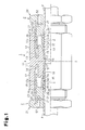
- Fig. 1 is a partial cross-sectional view illustrating a state immediately before the fastening of the duplex piping is started.
- This duplex pipe fitting 1 includes, as shown in Fig. 1 , a fitting main body 1 that has internal threads 12a as first thread portions at both ends in the axial direction, two coupling members 2 that have external threads 25a as second thread portions threaded to the internal threads 12a of the fitting main body and ferrules 3 integrally formed on the coupling members 2.
- Each coupling member 2 is attached to one of a pair of pipes P connected by the fitting main body 1.
- this duplex pipe fitting is formed symmetrically with respect to the radial center line A-A of the fitting main body 1. Therefore, the description below includes only the explanation about the coupling member 2 and the ferrule 3 on the right side and their functions. Explanation about the configuration of the left side is omitted in order to avoid overlap. Further, in the explanation of the configuration of the right side, the side corresponding to the fitting main body 1, that is, the left side in Fig. 1 , is referred to as the front side, while the side corresponding to the coupling member 2, that is, the right side in Fig. 1 , is referred to as the rear side. The same applies to the other embodiments described later.
- the fitting main body 1 has a symmetrical shape with respect to center line A-A as shown in Fig. 1 .
- the fitting main body 1 has a base portion 11 on its central part and bite type pipe connecting structures for connecting pipes P formed at both ends of the fitting main body 1. Therefore, on both sides of the base portion 11, internal thread cylindrical portions 12 are formed, which have, on their inner circumferential surface, the internal threads 12a as the first thread portions to which the coupling members 2 are threaded.
- the base portion 11 and the internal thread cylindrical portions 12 at both sides are integrally formed into a hexagon nut shape. Therefore, the base portion 11 and the internal thread cylindrical portions 12 are easily held with a general tool.
- the fitting main body 1 has two bosses 13 projecting from both sides of the base portion 11 into the respective internal thread cylindrical portions 12.
- an annular space 14 in which a protective cylindrical portion 26 of the coupling member 2 is inserted is formed on the outer circumferential surface of each boss 13, on the inner circumferential surface of each boss 13 extending from the boss 13 to the base portion 11, an insertion port 15 is formed, in which a pipe P is inserted at the time of pipe connecting.
- a communication hole 16 is formed between the insertion ports 15 on both sides. Between the insertion port 15 and the communication hole 16, a step (counter bore) 17 is formed. By causing the distal end of the pipe P inserted in the insertion port 15 to contact the step 17, the pipe P is held at a predetermined position.
- each cam surface 18 is formed at the entrance of each insertion port 15.
- Each cam surface 18 is continuous to the insertion port 15 on the side corresponding to the base portion 11 and formed like a cone with its diameter increasing toward the rear side (toward the coupling member 2).
- the inclination angle of the cam surface 18 relative to the central axis of the pipe fitting is formed so as to be greater than that of the tapered surface 32 of the distal end of the ferrule 3 described later.
- two coupling members 2 are threaded to both ends of the fitting main body 1, respectively. These coupling members 2 have the same structure and are attached in mutually opposite orientations. The coupling members 2 will now be explained below. Since the coupling members 2 on both sides have the same structure, only the coupling member threaded to the right side in Fig. 1 will be explained as mentioned above.
- the coupling member 2 has a pipe through hole 21 in the central axis, through which the pipe P is passed, as shown in Fig. 1 .
- a slit 22 having a U-shaped cross section is formed on the entire circumference of the coupling member 2 in such a manner as to divide the coupling member 2.
- a pipe connecting portion 23 which is threaded to the fitting main body 1 and has a pipe connecting mechanism is formed.
- a holding portion 24 which can be held with a general fastening tool is formed on a side of the slit 22 opposite to the fitting main body 1 (rear side).
- the position in the axial direction of the slit 22 substantially coincides with the end portion of the fitting main body 1, that is, the internal thread cylindrical portion 12 forming a tubular portion, in a state where the coupling member 2 is fastened to the fitting main body 1 (see Figs. 4 and 5 ) .
- the pipe connecting portion 23 also includes a base portion 25. On the outer circumferential surface of the side corresponding to the fitting main body 1 (front side) of the base portion 25, a protective cylindrical portion 26 for protecting a ferrule 3 is formed. On the outer circumferential surface from the protective cylindrical portion 26 to the base portion 25, an external thread 25a serving as a second thread portion to which the fitting main body 1 is threaded is formed.
- the holding portion 24 is formed into a hexagon nut shape so that it can be held with a general fastening tool.
- a thin-wall tubular coupling portion 27 is formed between the slit 22 and the pipe through hole 21, a thin-wall tubular coupling portion 27 is formed.
- the pipe connecting portion 23 and the holding portion 24 are connected to each other with the tubular coupling portion 27.
- the tubular coupling portion 27 is designed to have such a strength that it is cut when the tightening torque of the coupling member 2 for tightening the holding portion 24 reaches a value indicating the completion of fastening.
- the pipe connecting mechanism in this embodiment includes members such as the above-described ferrule 3, the external thread 25a, and the internal thread 12a.
- each machining hole 52 is formed at a position facing each corresponding engaging hole 51 and spaced at equal intervals on a circumference.
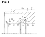
- the ferrule 3 is formed in an annular shape having a through hole 31, through which the pipe P is passed, at its central axis and connected to the base portion 25 with a thin-wall portion 4 extending in the radial direction at its rear end.
- the ferrule 3 is integrally formed with the coupling member 2.
- the ferrule 3 has a rear portion having a substantially constant wall thickness and a front portion having a tapered surface 32 on its outer circumference.
- the ferrule 3 is formed so that the tapered surface 32 tapers down toward the distal end.
- the inclination angle of the tapered surface 32 is set to be a little smaller than that of the above-mentioned cam surface 18.
- the rear surface 33 of the ferrule 3 is formed in such a manner as to face a pressing surface 28 formed on the base portion 25 via a first notch 34 which is recessed radially outward from the inner circumferential side.
- the first notch 34 has a generally V-shaped cross section.
- the first notch 34 includes a pair of wall surfaces which extend in the direction orthogonal to the central shaft line of the base portion 25 and face each other in the front and rear directions, respectively.
- a largest inner circumferential portion 34a of the first notch 34 is located on the cylindrical surface which has a shorter axial length.
- the outer circumference of the ferrule 3 and the front side of the thin-wall portion 4 are connected substantially at a right angle, as shown in Fig. 2 .
- the right-angle corner portion is formed as an incision 41 at the thin-wall portion 4.
- a thinnest wall portion 42 whose thickness is locally small is formed. Therefore, when an axial force acts on the coupling member 2, stress concentrates on the thinnest wall portion 42.
- a second notch 35 is provided on the inner circumferential surface in the vicinity of a distal end 3a of the ferrule 3.
- a third notch 36 is provided on the inner circumferential surface closer to the rear end of the ferrule 3.
- the second notch 35 is provided to facilitate deformation of the distal end 3a of the ferrule 3.
- the second notch 35 has a V-shaped cross section and is located on a plane where the rear cutting surface is orthogonal to the central axis. In a case where the coupling member 2 is tightened manually, the pipe P can be temporarily held by inserting the distal end 3a of the second notch 35, in a wedge-like fashion, between the pipe P and the insertion port 15.
- the crossing portion of the rear cutting surface and the inner circumferential surface of the second notch 35 forms an edge portion 3b.
- the edge portion 3b bends, thereby allowing the distal end 3a of the ferrule 3 to bite into the pipe P (see Fig. 3(c) ).
- the third notch 36 has a cross sectional which is substantially identical to that of the first notch 34.
- an annular thin-wall portion 37 (see Fig. 2 ) is formed between the innermost portion of the third notch 36 and the outer circumference of the rear part of the ferrule 3.
- the third notch 36 is formed and the annular thin-wall portion 37 is formed, so that the edge portion 3b of the distal end 3a of the ferrule 3 is deformed in such a manner as to bite into the pipe P and an edge portion 3c that forms the inner circumferential edge of the rear surface 33 is deformed in such a manner as to bite into the pipe P.
- the entire ferrule 3 is deformed at both ends toward the central axis with the third notch 36 interposed between them (see Fig. 3(c) ).
- the edge portion 3c at the rear end of the ferrule 3 is deformed in such a manner as to bite into the pipe P in order: (1) to hold the pipe P so that it is not disconnected, (2) to prevent vibration transmitted to the pipe P from being transmitted to the edge portion 3b, and (3) to maintain a high sealing performance and pipe retaining performance by biting of the edge portion 3b at the distal end 3a.
- the pipe P is made of copper and the fitting main body 1, the coupling member 2 and the ferrule 3 are made of brass materials.
- the above materials are most suitable for refrigeration systems and have general versatility.
- the method for connecting the pipe P using this duplex pipe fitting will be described.
- the pipe P is inserted into the pipe through hole 21 of the coupling member 2 to attach the coupling member 2 to the pipe P.
- the distal end of the pipe P is inserted into the insertion port 15 through the through hole 31 of the ferrule 3, and the coupling member 2 is threaded to the fitting main body 1 with the distal end of the pipe P contacting the step 17. This state is shown in Fig. 1 .
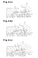
- the coupling member 2 is tightened manually, so that the distal end 3a of the ferrule 3 contacts the cam surface 18. If the coupling member 2 is further tightened from this state, the distal end 3a of the ferrule 3 is pressed in between the pipe P and the insertion port 15 and the pipe P is temporarily held. This state is shown in Fig. 3(a) .
- the ferrule 3 operates as an independent ferrule.
- the coupling member 2 is further tightened from the state where the cut end on the outer circumferential side continuous with the rear surface 33 is pressed by the pressing surface 28, the ferrule 3 is easily bent around the third notch 36 at its front and rear portions toward the central axis, because the part of the pressing surface 28 is formed as an inclined surface extending rearward from the largest inner circumferential portion 34a. Therefore, at the front portion of the third notch 36, the edge portion 3b is inclined around the third notch 36 in such a manner as to bite into the pipe P. In contrast, at the rear portion of the third notch 36, the edge portion 3c on the inner circumferential side of the rear surface 33 is inclined around the third notch 36 in such a manner as to bite into the pipe P (see Fig. 3(c) ).
- the rear portion of the ferrule 3 is deformed in such a manner as to be inclined around the third notch 36, so that the edge portion 3c bites into the pipe P.
- the third notch 36 is shaped so that the front surface and the rear surface forming the third notch 36 contact each other on their substantially entire surface to close the notch when the biting amount reaches a proper value.
- the shape is as mentioned above and has a generally V-shape as in the case with the first notch 34 as shown in the enlarged view of Fig. 2 .
- At the innermost portion, included is a narrow cylindrical surface 36a.
- the inclination around the third notch 36 is regulated to prevent an excessive biting of the edge portion 3c.
- the slit 22 is positioned so that the end of the internal thread cylindrical portion 12 of the fitting main body 1 and the side corresponding to the fitting main body 1 of the slit 22 substantially coincide with each other as shown in Fig. 4 when the bite amount of the edge portion 3b at the distal end 3a of the ferrule 3 and the bite amount of the edge portion 3c at the rear end portion of the ferrule 3 reach predetermined levels.
- the rotational torque for tightening the coupling member 2 reaches a value indicating the completion of fastening, as shown in Fig. 5 .
- the tubular coupling portion 27 is cut, and the holding portion 24 which projects from the internal thread cylindrical portion 12 of the fitting main body 1 is separated.
- tightening of the coupling member 2 is complete and connection of the pipe P is complete.
- a specialized tool 60 as shown in Fig. 6 , for example, is used.
- This specialized tool 60 has a generally semi-annular shaped base body 61 and a handle 62 attached to the base body 61.
- the inner diameter of an arc portion 63 of the base body 61 is formed to be a little larger than the outer diameter of the pipe P.
- On the side face of the base body 61 three engaging projections 64 which are engaged with the engaging holes 51 on the pipe connecting portion 23 are provided. These engaging projections 64 can be engaged with any three adjacent engaging holes of four engaging holes 51 provided on the pipe connecting portion 23.
- Three engaging projections 64 of the specialized tool 60 are fit into any three adjacent engaging holes 51 of the pipe connecting portion 23, respectively.
- the base body 61 is turned to loosen the threading with the fitting main body 1, so that the pipe P can be removed from the fitting main body 1.
- the pipe P can be removed by loosening the pipe connecting portion 23 without being cut. This facilitates the pipe disconnection work.
- the pipe P can be removed with the fitting main body 1 left attached.
- the pipe P can be re-connected to the fitting main body 1.
- the duplex pipe fitting according to the first embodiment having the above-mentioned configuration has the following advantages.
- the second embodiment is different from the first embodiment in that the positions of the internal thread 12a and the external thread 25a serving as a thread portion of the fitting main body 1 and the coupling member 2 are interchanged and that the ferrule 3 is formed as an independent ferrule which has two divided parts.
- the components that are the same as or correspond to those of the first embodiment are designated by the same reference numerals and their descriptions will be omitted or simplified.
- the fitting main body 1 includes an external thread 13a as a first thread portion formed on the outer circumference surface of a boss 13 formed on either end of a base portion 11, as shown in Fig. 7 .
- no tubular portion is formed on the outer circumference of the external thread 13a.
- the coupling member 2 which is threaded to either end of the fitting main body 1 does not have anything like a protective cylindrical portion in the first embodiment.
- an internal thread cylindrical portion 71 is formed on the side corresponding to the fitting main body 1 of the base portion 25.
- the internal thread cylindrical portion 71 includes an internal thread 71a as a second thread portion on its inner circumference which is threaded to the external thread 13a of the fitting main body 1.
- the entire outer circumference of the pipe connecting portion 23 is formed in a cylindrical shape.
- the ferrule 73 is formed by a front ferrule 74 and a back ferrule 75.
- pipe through holes 74a, 75a are formed, respectively.
- the rear surface of the front ferrule 74 and the front surface of the back ferrule 75 are each formed as an inclined surface, which inclines increasingly toward the central axis as they approach the fitting main body 1 from the rear, and the ferrules 74 and 75 contact each other.
- the second embodiment has the above-mentioned configuration and has the following advantages.
- the third embodiment is basically different from the second embodiment in that a flare type pipe connecting mechanism is used.
- the components that are the same as or correspond to those of the second embodiment are designated by the same reference numerals and their descriptions will be omitted or simplified.
- the fitting main body 1 has a flared receiving surface 81, instead of a cam surface, formed at the distal end of the boss 13, as shown in Fig. 8 . Further, in the central axis of the boss 13, a communication hole 82 which connects the bosses 13 provided at both ends to each other and has an inner diameter almost the same as that of the pipe P is formed.
- the pipe connecting portion 23 is formed on the side corresponding to the fitting main body 1 with the slit 22 interposed therebetween, and the holding portion 24 is formed on the side opposite to the fitting main body 1.
- the pipe connecting portion 23 has, on the side corresponding to the fitting main body 1 of the base portion 25, the internal thread cylindrical portion 71 with the internal thread 71a a formed on the inner circumferential surface.
- the pipe connecting portion 23 has a flared pressure surface 84 formed on the end face of the side corresponding to the fitting main body 1 of the base portion 25. The flared pressure surface 84 is pressed against a flare 83 formed on the pipe P.
- the flare type pipe fitting having the above-mentioned configuration is connected in the procedure mentioned below.
- the pipe P is inserted into the pipe through hole 21 of the coupling member 2, so that the pipe P is attached to the coupling member 2.
- the flare 83 is formed at the distal end of the pipe P using a separate tool.
- pressing the flare 83 against the flared receiving surface 81 the coupling member 2 is tightened to the fitting main body 1.
- the rotational torque for tightening the coupling member 2 reaches a value indicating the completion of fastening, the flare 83 gets caught between the flared receiving surface 81 and the flared pressure surface 84, as shown in Fig. 8 .
- the holding portion 24 (not shown) is separated, so that the fastening of the coupling member 2 is finished and the pipe connection is complete.
- the pipe connecting portion 23 cannot be held with a general fastening tool. Therefore, threading of the fitting main body 1 and the pipe connecting portion 23 cannot be loosened.
- the specialized tool 60 as shown in Fig. 6 is used to loosen threading of the fitting main body 1 and the pipe connecting portion 23.
- the third embodiment shows that the present invention is also applicable to such a case where the fitting main body 1 and the coupling member 2 have different pipe connecting mechanisms, and it has the same advantages as those of the invention according to the second embodiment.
- a duplex pipe fitting according to a fourth embodiment will now be described with reference to Figs. 9 to 11 .
- the fourth embodiment is different from the first embodiment in dimensions of each portion.
- a ferrule 3 is formed separately from the coupling member 2 and the ferrule 3 is temporarily held to the coupling member 2 before being assembled.
- Fig. 9 is a cross-sectional view of a duplex pipe fitting according to the fourth embodiment, showing a state when fastening is started.
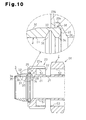
- Fig. 10 is a cross-sectional view of the same duplex pipe fitting, showing a state when the ferrule is temporarily held to the coupling member.
- Fig. 11 is a cross-sectional view of the same duplex pipe fitting, showing a state after pipe connecting is complete.
- the components that are the same as or correspond to those of the first embodiment are designated by the same reference numerals and their descriptions will be omitted or simplified.
- the duplex pipe fitting according to the fourth embodiment is basically the same as the first embodiment, except for the above-mentioned differences.
- the fitting main body 1 includes no protective cylindrical portion 26 like the one in the first embodiment formed to the coupling member 2. Therefore, the axial length of the annular space 14 is shorter than that of the first embodiment.
- a release port 5 is formed, through which the space (including the annular space 14) formed between the fitting main body 1 and the coupling member 2 when they are threaded to each other communicates with the outside. In a case where the space is cooled and water in the air freezes inside, the release port 5 releases an expansion force of ice caused by freezing to the outside.
- the pipe connecting portion 23 of the coupling member 2 includes a temporary holding mechanism for temporarily holding the ferrule 3 formed as a separate part, as shown in Fig. 10 .
- the pressing surface 28 for pressing the rear end of the ferrule 3 is formed on the pipe connecting portion 23.
- a large diameter portion 29a is formed forward of the pressing surface 28.
- the large diameter portion 29a and the projection 29b constitute a temporary holding mechanism of the coupling member 2.
- the inner diameters of the engaging holes 51 and the machining holes 52 in this embodiment are larger than those of the engaging hole 51 and the machining hole 52 in the first embodiment. Accordingly, the engaging projections 64 of the specialized tool 60 used for this duplex pipe fitting (see Fig. 6 according to the first embodiment) which are inserted in the engaging holes 51 need to have a larger diameter.
- annular projection 38 projecting radially outward is formed as a temporary holding mechanism.
- the projection 38 has an outer diameter which is slightly larger than the inner diameter of the annular projection 29b of the coupling member 2 and smaller than the inner diameter of the large diameter portion 29a.
- the axial length of the projection 38 is shorter than the axial length of the large diameter portion 29a.
- the projection 38 is pressed in the large diameter portion 29a, as shown in Fig. 10 .
- the projection 38 is held in the large diameter portion 29a as long as it is not pulled strongly, so that the ferrule 3 is temporarily held to the coupling member 2.
- the coupling member 2 to which the ferrule 3 is temporarily held is attached to the pipe P with the ferrule 3 being temporarily held, and the coupling member 2 is tightened manually so that the distal end of the ferrule 3 contacts the cam surface 18 (see Fig. 9 ).
- This is a state where fastening is started.
- the coupling member 2 is tightened manually, the distal end 3a of the ferrule 3 is pressed in a wedge-like fashion between the pipe P and the insertion port 15 as described above, so that the pipe P is temporarily held.
- the coupling member 2 is tightened using a fastening tool, the pipe P is fastened to the fitting main body 1 as in the case with the first embodiment (see Fig. 11 ).
- the fourth embodiment Since the fourth embodiment has the above-mentioned configuration, it has the same advantages as the first embodiment.
- the release port 5 is formed on the fitting main body 1. Therefore, even if moisture in the air freezes in the space including the annular space 14 formed between the fitting main body 1 and the coupling member 2, the expansion force of ice is released to the outside through the release port 5. Consequently, the sealing performance is not degraded by freezing of moisture in the air.
- this separation type air conditioner includes one outdoor unit 91 and a plurality of (four, in this case) indoor units 92 connected to the outdoor unit 91.
- the indoor unit 92 is a ceiling-embedded type unit installed above the ceiling.
- shut-off valves 93 are installed respectively, and main communication pipes 94 are connected to the shut-off valves 93 in the on-site piping installation works.
- branch pipes 95 are branched and connected to the main communication pipes 94 in the on-site piping installation works.
- Each branch pipe 95 is connected to a connecting portion 97 on the pipes drawn out of the indoor units 92 using a duplex pipe fitting 96.
- each indoor unit 92 is connected in parallel to the outdoor unit 91 through the main communication pipe 94, the branch pipe 95 and the duplex pipe fitting 96.
- the duplex pipe fitting 96 employs a bite type pipe connecting structure according to any of the embodiments described above. Accordingly, in a case where the indoor unit 92 is installed above the ceiling, the pipe cannot easily be disassembled. Brazing of pipes for preventing the pipes from being easily disassembled is not required. Therefore a safe piping installation work can be performed.
- the present invention may be modified as follows.
Landscapes
- Engineering & Computer Science (AREA)
- General Engineering & Computer Science (AREA)
- Mechanical Engineering (AREA)
- Joints With Pressure Members (AREA)
- Quick-Acting Or Multi-Walled Pipe Joints (AREA)
- Other Air-Conditioning Systems (AREA)
- Details Of Spanners, Wrenches, And Screw Drivers And Accessories (AREA)
Abstract
Description
- The present invention relates to a duplex pipe fitting having a thread portion at either end, and more particularly, to a duplex pipe fitting having a connecting structure that cannot be easily disassembled after pipes are connected thereto.
- As one type of pipe fittings used for fluid pipes through which fluid is passed, a simplex pipe fitting has been known that includes a first end and a second end. The first end has a pipe connecting port, to which a pipe is connected by brazing. The second end has a thread portion, to which a pipe is connected by threading a coupling member (nut), or by through screwing. Duplex pipe fittings are also known, which have a thread potion at either end, to which a pipe is connected by threading a coupling member (nut).
Fig. 13 shows an example of piping for a separation type air conditioner using the latter duplex pipe fitting, which is disclosed inPatent Document 1. - As shown in
Fig. 13 , apipe 102 is drawn to the outside from an indoor heat exchanger mounted in anindoor unit 101 of a prior art separation type air conditioner, and the distal end of thepipe 102 is connected to a flare typesimplex pipe fitting 103. Thesimplex pipe fitting 103 is provided as a connecting portion of theindoor unit 101. Also, anoutdoor unit 105 has a flare type simplex pipe fitting 106 serving as a connecting portion. A first connecting pipe (communication pipe) 104 and a second connectingpipe 107 are connected to the inside and outside connecting portions, and the first connectingpipe 104 and the second connectingpipe 107 are connected to each other at their distal ends. In this manner, theindoor unit 101 and theoutdoor unit 105 are connected to each other with the first and second connectingpipes duplex pipe fitting 108 is used for connecting the first connectingpipe 104 and the second connectingpipe 107 to each other. As an example of conventional duplex pipe fittings,Patent Document 2 discloses a specific structure of a duplex pipe fitting in addition toPatent Document 1. Specifically, the duplex pipe fitting disclosed inPatent Document 2 includes a fitting body having a thread portion to be connected to a pipe at either end, two nuts threaded to the thread portion, and sleeves accommodated in the nuts. - The
simplex pipe fittings duplex pipe fitting 108, which are used in the above example of piping, are installed by tightening the coupling members (nuts in some cases) with fastening tools. The fastening is continuously executed until the tightening torque reaches a value that indicates the completion of fastening. When the tightening torque reaches the completion indicating value, the fastening is finished, and the pipe connecting is ended. After the completion of the pipe connecting, the first and second connectingpipes pipe fittings pipe fittings pipes - However, recently, the handling of chlorofluorocarbon gas, which is in heavy usage as refrigerants of refrigeration apparatuses, has become stricter year by year. This is because chlorofluorocarbon gas is a factor of generating problems of ozone layer destruction, global warming and the like when discharged into the atmosphere. In recent years, a structure of pipe fittings that cannot be easily disassembled has been needed for parts to which pipes are connected with pipe fittings.
- In
Fig. 13 , if theindoor unit 101 is located above the ceiling, a pipe fitting having a structure that cannot be easily loosened is desired. However, no suitable pipe fittings exist that meet such demands. That is, no suitable pipe fitting that connects thepipe 102 drawn from theindoor unit 101 to the first connectingpipe 104 exists. If theindoor unit 101 is installed above the ceiling by means of brazing, all possible measures must be taken to ensure fire prevention. - Patent Document 1: Japanese Laid-Open Patent Publication No.
11-141921 - Patent Document 2: Japanese Laid-Open Patent Publication No.
2007-120741 - Accordingly, it is an objective of the present invention to provide a duplex pipe fitting that cannot be loosened using a general fastening tool after pipe connecting is complete. Another objective of the present invention is to provide a specialized tool for loosening thread portions of the duplex pipe fitting and to provide a refrigeration system and an air conditioner each employing the duplex pipe fitting.
- To achieve the foregoing objective and in accordance with one aspect of the present invention, a duplex pipe fitting is provided that includes a fitting main body having a pair of first thread portions and a pair of coupling members having second thread portions which are threaded to the respective first thread portions of the fitting main body while being attached to pipes to be connected to the fitting main body. Each of the coupling member is threaded to the fitting main body so that two pipes are connected to each other with the fitting main body. Each of the coupling members has a holding portion including a holding surface formed of a pair of or a plurality of pairs of planes facing each other. The holding portion is capable of being held with a general fastening tool. At least a part of the holding portion including the holding surface is separated in the course of pipe connecting.
- "Separation" includes the following cases. (1) A case where an integrally formed portion is cut or broken. (2) A case where parts that have been separately formed are joined by engaging means such as adhesion or engagement are cut or broken at the joint portion. (3) A case where parts that are engaged with each other under normal use conditions, but are disengaged under a certain condition are disengaged under the certain condition. The last case (3) includes a case where, when the rotational torque for tightening the coupling member to the fitting main body reaches a value indicating the completion of fastening, the coupling mechanism formed between a holding surface and the thread portion operates such that the rotational torque is no longer transmitted from the holding surface to the thread portion.
- The duplex pipe fitting according to the present invention having such structural characteristics allows a pipe to be connected to each end of a fitting main body that has a threaded portion at either end in the axial direction. Also, since at least a part of the holding portion that includes the holding surface is formed by the separation in the course of the pipe connecting, general fastening tools can be no longer used after the pipe connecting is complete. Therefore, the thread portions of the pipe fitting cannot be easily loosened, and the pipes cannot be easily removed by loosening the thread portions. As a result, inadvertent leakage and discharge of refrigerant gas into the atmosphere are prevented. Further, in a case where the thread portions of the fitting main body and the coupling member need to be loosened, such loosening has to be performed by a specialist. This reduces the unwanted discharging of chlorofluorocarbon gas into the atmosphere.
- The part including the holding surface can be configured to be separated when a rotational torque for tightening the coupling member to the fitting main body reaches a value indicating the completion of fastening. In this case, the strength of the parts to be separated needs to be set in accordance with the rotational torque. Since the portion including the holding surface is separated at the same time as the fastening of the coupling member is finished, the fastening operation is simplified. When the portion including the holding surface is separated, the rotational torque abruptly drops. Thus, the worker should be watchful about such a torque drop.
- The coupling member preferably includes a pipe through hole extending along a central axis, a slit formed on the entire circumference of the coupling member in such a manner as to divide the coupling member into two parts, and a thin-wall tubular coupling portion formed between the slit and the pipe through hole. A portion of the coupling member that is on a side opposite to the fitting main body of the slit is formed as the holding portion, and a portion of the coupling member that is on the same side as the fitting main body of the slit is formed as a pipe connecting portion. The pipe connecting portion includes the thread portions that are threaded to the fitting main body and constituting a pipe connecting mechanism for hermetically joining the fitting main body and the pipe. The part including the holding surface is separated at the tubular coupling portion when the rotational torque for tightening the coupling member to the fitting main body reaches the value indicating the completion of fastening.
- In this configuration, when the rotational torque for tightening the coupling member reaches the value indicating the completion of fastening, the entire holding portion, which is held with a general fastening tool, is separated from the pipe connecting portion threaded to the fitting main body, so that the fastening process of the coupling member is finished. Therefore, after the pipes are connected, the pipe connecting portion, which is threaded to the fitting main body, cannot be easily removed. Although the holding portion becomes movable freely on the pipe, this causes no particular problem.
- Also, in this case, the fitting main body preferably has a cylindrical portion in which the entire pipe connecting portion is accommodated in a state after the fastening is complete, and the coupling member is preferably located at a position where the slit substantially coincides with the end of the cylindrical portion in a state after the fastening is complete. In this configuration, the tubular coupling portion is cut at the same time when the fastening process of the coupling member is complete, so that the entire pipe connecting portion is accommodated in the fitting main body, and the holding portion is separated. Therefore, the thread portion is more reliably prevented from being easily loosened, for example, to remove the pipe, by anybody.
- Further, a plurality of engaging holes are preferably formed on an end face opposite to the fitting main body of the pipe connecting portion. In this configuration, the pipe connecting portion is easily loosened by using the specialized tool having engaging projections engaged with the engaging holes. The engaging holes are formed as engaging portions with which the specialized tool is engaged, but do not project with respect to the slit. This allows the width of the slit to be reduced, so that the pipe fitting is compact.
- The plurality of engaging holes are preferably formed in such a manner as to extend in the axial direction, and a plurality of machining holes used for machining the plurality of engaging holes preferably pass through the holding portion. The machining holes are formed at positions corresponding to the engaging holes on the holding portion. In this configuration, despite the existence of the holding portion, the engaging hole can be formed from a side of the holding body opposite to the fitting main body. Also, since the inner diameter of the machining hole is the same as the inner diameter of the engaging hole, these holes can be formed simultaneously.
- The plurality of engaging holes are preferably spaced at equal intervals on a circumference. In this configuration, when the specialized tool having engaging projections to be engaged with the engaging holes is used, the engaging projection of the specialized tool can be engaged with the engaging hole. The specialized tool is easy to use.
- Also, the specialized tool of the present invention has engaging holes formed on an end face of the pipe connecting portion opposite to the fitting main body as described above, and is used for a duplex pipe fitting. The specialized tool is characterized by a generally semi-annular shaped base body which has an inner diameter larger than the outer diameter of the pipe, a handle attached to the base body, and engaging projections formed on the side face of the base body, which are engaged with the engaging holes. Therefore, by using the specialized tool, the pipe connecting portion, to which the fitting main body is threaded, can be removed without removing the holding portion from the pipe. The piping can be easily redone.
- According to another aspect of the present invention, a refrigeration system using the above described duplex pipe fitting in a refrigerant circuit is provided. Thus, the durability of the refrigeration system is improved.
- In accordance with another aspect of the present invention, a separation type air conditioner is provided. An indoor unit installed in a room and an outdoor unit installed outside a room are connected to each other with a communication pipe installed on site, and the air conditioner is characterized in that the above described duplex pipe fitting is used for connection of the communication pipe. In this configuration, when the indoor unit and the outdoor unit are connected by the communication pipe, the pipe cannot be easily disassembled after being installed.
- In accordance with another aspect of the present invention, a separation type air conditioner is provided, in which an indoor unit installed above a ceiling and an outdoor unit installed outside a room are connected to each other with a communication pipe installed on site. The air conditioner is characterized in that the communication pipe is connected above the ceiling with the above described duplex pipe fitting. In this configuration, the indoor unit and the communication pipe can be connected above the ceiling using the above described duplex pipe fitting, without brazing, in such a manner that the pipes cannot be easily disassembled.
-
-
Fig. 1 is a partial cross-sectional view of a duplex pipe fitting according to a first embodiment of the present invention, showing a state before fastening is started; -
Fig. 2 is an enlarged cross-sectional view illustrating the ferrule and its surroundings in the duplex pipe coupling shown inFig. 1 ; -
Figs. 3 are cross-sectional views illustrating the ferrule and its surroundings during the fastening process of the duplex pipe fitting ofFig. 1 , whereFig. 3(a) shows a state of temporary joint in which the distal end of the ferrule is caused to bite into the pipe by manual fastening,Fig. 3(b) shows a state in which the ferrule is separated from the coupling member, andFig. 3(c) shows a state where the fastening is complete; -
Fig. 4 is a partial cross-sectional view illustrating a state immediately before the fastening of the duplex pipe fitting shown inFig. 1 is complete; -
Fig. 5 is a partial cross-sectional view illustrating a state after the fastening of the duplex pipe fitting shown inFig. 1 is complete; -
Fig. 6 is a perspective view showing one example of a specialized tool for loosening the threading of the coupling member in the duplex pipe fitting shown inFig. 1 ; -
Fig. 7 is a partial cross-sectional view of a duplex pipe fitting according to a second embodiment of the present invention, showing a state when fastening is started; -
Fig. 8 is a partial cross-sectional view of a duplex pipe fitting according to a third embodiment of the present invention, showing a state immediately before the fastening is complete; -
Fig. 9 is a partial cross-sectional view of a duplex pipe fitting according to a fourth embodiment of the present invention, showing a state when fastening is started; -
Fig. 10 is a cross-sectional view of the duplex pipe fitting shown inFig. 9 , illustrating a state in which the ferrule is temporarily held by the coupling member; -
Fig. 11 is a cross-sectional view illustrating a state in which pipe connecting using the duplex pipe fitting shown inFig. 9 is complete; -
Fig. 12 is a block diagram showing a piping system of a separation type air conditioner according to a modified embodiment; and -
Fig. 13 is a diagram showing a piping system of a conventional separation type air conditioner. - A pipe fitting according to a first embodiment will now be described with reference to
Figs. 1 to 6 . The pipe fitting of the first embodiment is a duplex pipe fitting used in a refrigerant circuit of a refrigerating device used, for example, as a heat pump type water heating device.Fig. 1 is a partial cross-sectional view illustrating a state immediately before the fastening of the duplex piping is started. - This duplex pipe fitting 1 includes, as shown in
Fig. 1 , a fittingmain body 1 that hasinternal threads 12a as first thread portions at both ends in the axial direction, twocoupling members 2 that haveexternal threads 25a as second thread portions threaded to theinternal threads 12a of the fitting main body andferrules 3 integrally formed on thecoupling members 2. Eachcoupling member 2 is attached to one of a pair of pipes P connected by the fittingmain body 1. - Also, this duplex pipe fitting is formed symmetrically with respect to the radial center line A-A of the fitting
main body 1. Therefore, the description below includes only the explanation about thecoupling member 2 and theferrule 3 on the right side and their functions. Explanation about the configuration of the left side is omitted in order to avoid overlap. Further, in the explanation of the configuration of the right side, the side corresponding to the fittingmain body 1, that is, the left side inFig. 1 , is referred to as the front side, while the side corresponding to thecoupling member 2, that is, the right side inFig. 1 , is referred to as the rear side. The same applies to the other embodiments described later. - The fitting
main body 1 has a symmetrical shape with respect to center line A-A as shown inFig. 1 . The fittingmain body 1 has abase portion 11 on its central part and bite type pipe connecting structures for connecting pipes P formed at both ends of the fittingmain body 1. Therefore, on both sides of thebase portion 11, internal threadcylindrical portions 12 are formed, which have, on their inner circumferential surface, theinternal threads 12a as the first thread portions to which thecoupling members 2 are threaded. Thebase portion 11 and the internal threadcylindrical portions 12 at both sides are integrally formed into a hexagon nut shape. Therefore, thebase portion 11 and the internal threadcylindrical portions 12 are easily held with a general tool. - Also, the fitting
main body 1 has twobosses 13 projecting from both sides of thebase portion 11 into the respective internal threadcylindrical portions 12. On the outer circumferential surface of eachboss 13, anannular space 14 in which a protectivecylindrical portion 26 of thecoupling member 2 is inserted is formed. Also, on the inner circumferential surface of eachboss 13 extending from theboss 13 to thebase portion 11, aninsertion port 15 is formed, in which a pipe P is inserted at the time of pipe connecting. In addition, acommunication hole 16 is formed between theinsertion ports 15 on both sides. Between theinsertion port 15 and thecommunication hole 16, a step (counter bore) 17 is formed. By causing the distal end of the pipe P inserted in theinsertion port 15 to contact thestep 17, the pipe P is held at a predetermined position. - Also, at the entrance of each
insertion port 15, acam surface 18 is formed. Eachcam surface 18 is continuous to theinsertion port 15 on the side corresponding to thebase portion 11 and formed like a cone with its diameter increasing toward the rear side (toward the coupling member 2). The inclination angle of thecam surface 18 relative to the central axis of the pipe fitting is formed so as to be greater than that of the taperedsurface 32 of the distal end of theferrule 3 described later. - As mentioned above, two
coupling members 2 are threaded to both ends of the fittingmain body 1, respectively. Thesecoupling members 2 have the same structure and are attached in mutually opposite orientations. Thecoupling members 2 will now be explained below. Since thecoupling members 2 on both sides have the same structure, only the coupling member threaded to the right side inFig. 1 will be explained as mentioned above. - The
coupling member 2 has a pipe throughhole 21 in the central axis, through which the pipe P is passed, as shown inFig. 1 . On thecoupling member 2, aslit 22 having a U-shaped cross section is formed on the entire circumference of thecoupling member 2 in such a manner as to divide thecoupling member 2. On the side corresponding to the fitting main body 1 (front side) of theslit 22, apipe connecting portion 23 which is threaded to the fittingmain body 1 and has a pipe connecting mechanism is formed. On a side of theslit 22 opposite to the fitting main body 1 (rear side), a holdingportion 24 which can be held with a general fastening tool is formed. The position in the axial direction of theslit 22 substantially coincides with the end portion of the fittingmain body 1, that is, the internal threadcylindrical portion 12 forming a tubular portion, in a state where thecoupling member 2 is fastened to the fitting main body 1 (seeFigs. 4 and5 ) . - The
pipe connecting portion 23 also includes abase portion 25. On the outer circumferential surface of the side corresponding to the fitting main body 1 (front side) of thebase portion 25, a protectivecylindrical portion 26 for protecting aferrule 3 is formed. On the outer circumferential surface from the protectivecylindrical portion 26 to thebase portion 25, anexternal thread 25a serving as a second thread portion to which the fittingmain body 1 is threaded is formed. - Also, the holding
portion 24 is formed into a hexagon nut shape so that it can be held with a general fastening tool. Between theslit 22 and the pipe throughhole 21, a thin-walltubular coupling portion 27 is formed. Thepipe connecting portion 23 and the holdingportion 24 are connected to each other with thetubular coupling portion 27. Thetubular coupling portion 27 is designed to have such a strength that it is cut when the tightening torque of thecoupling member 2 for tightening the holdingportion 24 reaches a value indicating the completion of fastening. The pipe connecting mechanism in this embodiment includes members such as the above-describedferrule 3, theexternal thread 25a, and theinternal thread 12a. - On the side opposite to the fitting main body 1 (rear side) of the
pipe connecting portion 23, four engagingholes 51 which are circular and have a predetermined depth are formed. These engagingholes 51 function as a portion that is engaged with an engaging portion of a specialized tool described later. On the holdingportion 24, fourmachining holes 52 are formed, which enable the engagingholes 51 to be machined from the side corresponding to the fitting main body 1 (rear side) of the holdingportion 24. Eachmachining hole 52 is formed at a position facing each corresponding engaginghole 51 and spaced at equal intervals on a circumference. - As shown in
Fig. 2 , theferrule 3 is formed in an annular shape having a throughhole 31, through which the pipe P is passed, at its central axis and connected to thebase portion 25 with a thin-wall portion 4 extending in the radial direction at its rear end. Theferrule 3 is integrally formed with thecoupling member 2. - Also, as shown in
Fig. 2 , theferrule 3 has a rear portion having a substantially constant wall thickness and a front portion having a taperedsurface 32 on its outer circumference. Theferrule 3 is formed so that the taperedsurface 32 tapers down toward the distal end. The inclination angle of the taperedsurface 32 is set to be a little smaller than that of the above-mentionedcam surface 18. Therear surface 33 of theferrule 3 is formed in such a manner as to face apressing surface 28 formed on thebase portion 25 via afirst notch 34 which is recessed radially outward from the inner circumferential side. Thefirst notch 34 has a generally V-shaped cross section. Thefirst notch 34 includes a pair of wall surfaces which extend in the direction orthogonal to the central shaft line of thebase portion 25 and face each other in the front and rear directions, respectively. A largest innercircumferential portion 34a of thefirst notch 34 is located on the cylindrical surface which has a shorter axial length. - On the other hand, the outer circumference of the
ferrule 3 and the front side of the thin-wall portion 4 (that is, the proximal side of the ferrule 3) are connected substantially at a right angle, as shown inFig. 2 . The right-angle corner portion is formed as anincision 41 at the thin-wall portion 4. At the portion forming theincision 41, athinnest wall portion 42 whose thickness is locally small is formed. Therefore, when an axial force acts on thecoupling member 2, stress concentrates on thethinnest wall portion 42. - On the inner circumferential surface in the vicinity of a
distal end 3a of theferrule 3, asecond notch 35 is provided. On the inner circumferential surface closer to the rear end of theferrule 3, athird notch 36 is provided. Thesecond notch 35 is provided to facilitate deformation of thedistal end 3a of theferrule 3. Thesecond notch 35 has a V-shaped cross section and is located on a plane where the rear cutting surface is orthogonal to the central axis. In a case where thecoupling member 2 is tightened manually, the pipe P can be temporarily held by inserting thedistal end 3a of thesecond notch 35, in a wedge-like fashion, between the pipe P and theinsertion port 15. Also, the crossing portion of the rear cutting surface and the inner circumferential surface of thesecond notch 35 forms anedge portion 3b. Theedge portion 3b bends, thereby allowing thedistal end 3a of theferrule 3 to bite into the pipe P (seeFig. 3(c) ). - The
third notch 36 has a cross sectional which is substantially identical to that of thefirst notch 34. By formation of thethird notch 36, an annular thin-wall portion 37 (seeFig. 2 ) is formed between the innermost portion of thethird notch 36 and the outer circumference of the rear part of theferrule 3. In this manner, thethird notch 36 is formed and the annular thin-wall portion 37 is formed, so that theedge portion 3b of thedistal end 3a of theferrule 3 is deformed in such a manner as to bite into the pipe P and anedge portion 3c that forms the inner circumferential edge of therear surface 33 is deformed in such a manner as to bite into the pipe P. Consequently, theentire ferrule 3 is deformed at both ends toward the central axis with thethird notch 36 interposed between them (seeFig. 3(c) ). In addition to biting of theedge portion 3b at thedistal end 3a of theferrule 3, theedge portion 3c at the rear end of theferrule 3 is deformed in such a manner as to bite into the pipe P in order: (1) to hold the pipe P so that it is not disconnected, (2) to prevent vibration transmitted to the pipe P from being transmitted to theedge portion 3b, and (3) to maintain a high sealing performance and pipe retaining performance by biting of theedge portion 3b at thedistal end 3a. - In the above configuration, the pipe P is made of copper and the fitting
main body 1, thecoupling member 2 and theferrule 3 are made of brass materials. The above materials are most suitable for refrigeration systems and have general versatility. - Next, the method for connecting pipes of this duplex pipe fitting having the above-mentioned configuration will now be described with reference to
Fig. 1 andFigs. 3 to 6 . The pipe connection on the right side and the pipe connection on the left side shown inFig. 1 are the same, except that they are conducted symmetrically. Therefore, in the description below, the pipe connecting on the right side will be explained. - The method for connecting the pipe P using this duplex pipe fitting will be described. First, the pipe P is inserted into the pipe through
hole 21 of thecoupling member 2 to attach thecoupling member 2 to the pipe P. Then, the distal end of the pipe P is inserted into theinsertion port 15 through the throughhole 31 of theferrule 3, and thecoupling member 2 is threaded to the fittingmain body 1 with the distal end of the pipe P contacting thestep 17. This state is shown inFig. 1 . - From this state, the
coupling member 2 is tightened manually, so that thedistal end 3a of theferrule 3 contacts thecam surface 18. If thecoupling member 2 is further tightened from this state, thedistal end 3a of theferrule 3 is pressed in between the pipe P and theinsertion port 15 and the pipe P is temporarily held. This state is shown inFig. 3(a) . - Thereafter, the tapered
surface 32 at the front side of thesecond notch 35 of theferrule 3 contacts thecam surface 18, and a larger rotational torque is required for further tightening of thecoupling member 2. Therefore, in the subsequent processes, a general fastening tool is used to tighten thecoupling member 2 to the fittingmain body 1. As with the conventional cases, in the above tightening process, thecoupling member 2 is tightened with thedistal end 3a of theferrule 3 pressed against thecam surface 18, so that a forward force in the axial direction acts on the thin-wall portion 4. At this time, stress concentrates on the crossing portion of the outer circumferential surface of theferrule 3 and the front surface of the thin-wall portion 4, that is, thethinnest wall portion 42 having an incision 41 (seeFig. 3(a) ). As a result, the thin-wall portion 4 is cut at thethinnest wall portion 42, and the outer circumferential end which is continuous with therear surface 33 contacts the pressing surface 28 (seeFig. 3(b) ). - Thereafter, the
ferrule 3 operates as an independent ferrule. In other words, when thecoupling member 2 is further tightened from the state where the cut end on the outer circumferential side continuous with therear surface 33 is pressed by thepressing surface 28, theferrule 3 is easily bent around thethird notch 36 at its front and rear portions toward the central axis, because the part of thepressing surface 28 is formed as an inclined surface extending rearward from the largest innercircumferential portion 34a. Therefore, at the front portion of thethird notch 36, theedge portion 3b is inclined around thethird notch 36 in such a manner as to bite into the pipe P. In contrast, at the rear portion of thethird notch 36, theedge portion 3c on the inner circumferential side of therear surface 33 is inclined around thethird notch 36 in such a manner as to bite into the pipe P (seeFig. 3(c) ). - Furthermore, the rear portion of the
ferrule 3 is deformed in such a manner as to be inclined around thethird notch 36, so that theedge portion 3c bites into the pipe P. Thethird notch 36 is shaped so that the front surface and the rear surface forming thethird notch 36 contact each other on their substantially entire surface to close the notch when the biting amount reaches a proper value. The shape is as mentioned above and has a generally V-shape as in the case with thefirst notch 34 as shown in the enlarged view ofFig. 2 . At the innermost portion, included is a narrow cylindrical surface 36a. Accordingly, in theferrule 3 according to the first embodiment, after the front surface and the rear surface forming thethird notch 36 contact each other on their substantially entire surfaces, the inclination around thethird notch 36 is regulated to prevent an excessive biting of theedge portion 3c. - In this manner, the
slit 22 is positioned so that the end of the internal threadcylindrical portion 12 of the fittingmain body 1 and the side corresponding to the fittingmain body 1 of theslit 22 substantially coincide with each other as shown inFig. 4 when the bite amount of theedge portion 3b at thedistal end 3a of theferrule 3 and the bite amount of theedge portion 3c at the rear end portion of theferrule 3 reach predetermined levels. When thecoupling member 2 is further tightened, the rotational torque for tightening thecoupling member 2 reaches a value indicating the completion of fastening, as shown inFig. 5 . Then, thetubular coupling portion 27 is cut, and the holdingportion 24 which projects from the internal threadcylindrical portion 12 of the fittingmain body 1 is separated. Thus, tightening of thecoupling member 2 is complete and connection of the pipe P is complete. - Next, the method for loosening the pipe connection that has been fastened as described above using a specialized tool will now be described. In this case, a
specialized tool 60 as shown inFig. 6 , for example, is used. Thisspecialized tool 60 has a generally semi-annular shapedbase body 61 and ahandle 62 attached to thebase body 61. The inner diameter of anarc portion 63 of thebase body 61 is formed to be a little larger than the outer diameter of the pipe P. On the side face of thebase body 61, three engagingprojections 64 which are engaged with the engagingholes 51 on thepipe connecting portion 23 are provided. These engagingprojections 64 can be engaged with any three adjacent engaging holes of fourengaging holes 51 provided on thepipe connecting portion 23. - Three engaging
projections 64 of thespecialized tool 60 are fit into any three adjacent engagingholes 51 of thepipe connecting portion 23, respectively. Using thehandle 62 of thespecialized tool 60, thebase body 61 is turned to loosen the threading with the fittingmain body 1, so that the pipe P can be removed from the fittingmain body 1. According to this method for loosening the pipe connection, the pipe P can be removed by loosening thepipe connecting portion 23 without being cut. This facilitates the pipe disconnection work. Also, the pipe P can be removed with the fittingmain body 1 left attached. Using anew coupling member 2, the pipe P can be re-connected to the fittingmain body 1. - The duplex pipe fitting according to the first embodiment having the above-mentioned configuration has the following advantages.
- (1) To the fitting
main body 1 including the first thread portion (internal thread 12a) at either end in the axial direction, the pipe P can be connected at either end. In other words, the fittingmain body 1 includes the internal threadcylindrical portion 12 as the first thread portion at either end in the axial direction, which has thecam surface 18 having a pipe connecting mechanism and theinternal thread 12a on the inner circumferential surface. Thecoupling member 2 including theexternal thread 25a and formed integrally with theferrule 3 is formed in such a manner as to be threaded to the above-mentionedinternal thread 12a. Consequently, the pipe P can be connected to either end of the fittingmain body 1 in a biting manner. - (2) In a case where the
coupling member 2 is fastened to the fittingmain body 1, the pipe P is sealed to the fittingmain body 1 and supported to the fittingmain body 1 when the rotational torque for tightening thecoupling member 2 to the fittingmain body 1 reaches a value indicating the completion of fastening. Further, at this time, thetubular coupling portion 27 of thecoupling member 2 is cut, the tightening of thecoupling member 2 is finished, and the pipe connecting work is complete. Accordingly, after pipe connection, thepipe connecting portion 23 cannot be easily loosened because the holdingportion 24 is separated from thepipe connecting portion 23 to be threaded to the fittingmain body 1. Consequently, the pipe P cannot be easily removed, and inadvertent leakage and discharge of refrigerant gas into the atmosphere are prevented. - (3) The fitting
main body 1 includes the internal threadcylindrical portion 12 as a tubular portion in which the entirepipe connecting portion 23 of thecoupling member 2 is accommodated when the fastening is complete. On the other hand, thecoupling member 2 is located at a position where theslit 22 substantially coincides with the end portion of the internal threadcylindrical portion 12 as a tubular portion. Therefore, after the holdingportion 24 is cut, the remainingpipe connecting portion 23 is entirely accommodated within the fittingmain body 1. Consequently, in this embodiment, the thread portion of thepipe connecting portion 23 to the fittingmain body 1 is more reliably prevented from being easily loosened or loosened to remove the pipe P by anybody. - (4) On the end face opposite to the fitting main body 1 (rear side) of the
pipe connecting portion 23, the plurality of engagingholes 51 are formed. Therefore, thepipe connecting portion 23 can easily be loosened by using thespecialized tool 60 having the engagingprojections 64 which are engaged with the engaging holes 51. The engagingholes 51 are formed as an engaging portion with which thespecialized tool 60 is engaged but configured so as not to project to theslit 22. This configuration allows the width of theslit 22 to be reduced, so that the pipe fitting becomes compact. - (5) The engaging
holes 51 are formed in such a manner as to extend in the axial direction. At each position corresponding to the engagingholes 51 on the holdingportion 24, machining holes 52 used for machining the engagingholes 51 which pass through the holdingportion 24 are formed. Therefore, despite the existence of the holdingportion 24, the engagingholes 51 can be machined from the side opposite to the fitting main body 1 (rear side) of the holdingportion 24. Also, since the diameter of themachining hole 52 is the same as the diameter of the engaginghole 51, theseholes - (6) Since the engaging
holes 51 are spaced at equal intervals on a circumference, the engagingprojections 64 provided on thespecialized tool 60 can be engaged with any engagingholes 51 of thepipe connecting portion 23. Thus, thespecialized tool 60 is easy to use. - (7) The
specialized tool 60 includes thebase body 61 having thearc portion 63 with an inner diameter larger than the outer diameter of the pipe P, thehandle 62 attached to thebase body 61 and the engagingprojections 64 formed on the side face of thebase body 61, which are engaged with the engaging holes 51. Therefore, by using thespecialized tool 60, thepipe connecting portion 23 threaded to the fittingmain body 1 can be removed without removing the holdingportion 24 from the pipe P. This facilitates reconnection of the pipe P. - (8) In a refrigeration system using the above described duplex pipe fitting in a refrigeration circuit, two pipes P can easily be connected, but the connected pipes P cannot easily be removed. Therefore, leakage of refrigerant can be strictly controlled.
- Next, a second embodiment will now be described with reference to
Fig. 7 . The second embodiment is different from the first embodiment in that the positions of theinternal thread 12a and theexternal thread 25a serving as a thread portion of the fittingmain body 1 and thecoupling member 2 are interchanged and that theferrule 3 is formed as an independent ferrule which has two divided parts. InFig. 7 , the components that are the same as or correspond to those of the first embodiment are designated by the same reference numerals and their descriptions will be omitted or simplified. - The fitting
main body 1 according to the second embodiment includes anexternal thread 13a as a first thread portion formed on the outer circumference surface of aboss 13 formed on either end of abase portion 11, as shown inFig. 7 . Differently from the first embodiment, no tubular portion is formed on the outer circumference of theexternal thread 13a. Also, thecoupling member 2 which is threaded to either end of the fittingmain body 1 does not have anything like a protective cylindrical portion in the first embodiment. Instead, an internal threadcylindrical portion 71 is formed on the side corresponding to the fittingmain body 1 of thebase portion 25. The internal threadcylindrical portion 71 includes aninternal thread 71a as a second thread portion on its inner circumference which is threaded to theexternal thread 13a of the fittingmain body 1. The entire outer circumference of thepipe connecting portion 23 is formed in a cylindrical shape. - The
ferrule 73 is formed by afront ferrule 74 and aback ferrule 75. In the central axis portion of thefront ferrule 74 and theback ferrule 75, pipe throughholes front ferrule 74 and the front surface of theback ferrule 75 are each formed as an inclined surface, which inclines increasingly toward the central axis as they approach the fittingmain body 1 from the rear, and theferrules - In the duplex pipe fitting having this configuration, when the
ferrule 73 is pressed by thepressing surface 28, the edge portion 76 at the rear end of theferrule 73 bites into the pipe P and the pipe P is supported in the fittingmain body 1 and thepipe connecting portion 23. Theferrule 73 is pressed by thepressing surface 28, so that thedistal end 77 offront ferrule 74 bites into the pipe P to seal the space between the pipe P and theferrule 73. At the same time, the outer circumferential tapered surface 78 of thefront ferrule 74 closely contacts thecam surface 18, and the space between theferrule 73 and thecam surface 18 is sealed.Fig. 7 shows a state where tightening of thecoupling member 2 has just been started. A state where the edge portion 76 at the rear end and thedistal end 77 bite into the pipe P is not shown. - The second embodiment has the above-mentioned configuration and has the following advantages.
- (1) At either end in the axial direction of the fitting
main body 1, thecam surface 18 and theexternal thread 13a as the first thread portion are formed. Therefore, by fastening thecoupling member 2 attached to the pipe P with theferrule 73 interposed therebetween to the fittingmain body 1, the pipe P can be connected to the fittingmain body 1. - (2) In a state after pipe connection is complete, as in the case with the first embodiment, the holding
portion 24 is separated from thepipe connecting portion 23 to be threaded to the fittingmain body 1. Therefore, the threading of thepipe connecting portion 23 is not easily loosened. Consequently, the pipe P cannot easily be removed, and inadvertent leakage and discharge of refrigerant gas into the atmosphere are prevented. - (3) Further, in the second embodiment, as in the case with the first embodiment, a plurality of engaging
holes 51 are formed on the end face opposite to the fittingmain body 1 of thepipe connecting portion 23 and machining holes 52 are formed on the holdingportion 24. Therefore, the second embodiment has the same advantages as the advantages (4), (5) and (8) in the first embodiment. Also, thespecialized tool 60 similar to that in the first embodiment can be used. - Next, a third embodiment will now be described with reference to
Fig. 8 . The third embodiment is basically different from the second embodiment in that a flare type pipe connecting mechanism is used. In this figure, the components that are the same as or correspond to those of the second embodiment are designated by the same reference numerals and their descriptions will be omitted or simplified. - The fitting
main body 1 according to the third embodiment has a flared receivingsurface 81, instead of a cam surface, formed at the distal end of theboss 13, as shown inFig. 8 . Further, in the central axis of theboss 13, acommunication hole 82 which connects thebosses 13 provided at both ends to each other and has an inner diameter almost the same as that of the pipe P is formed. - On each of the pair of
coupling members 2 threaded to the either end of the fittingmain body 1, as in the case with the second embodiment, thepipe connecting portion 23 is formed on the side corresponding to the fittingmain body 1 with theslit 22 interposed therebetween, and the holdingportion 24 is formed on the side opposite to the fittingmain body 1. Thepipe connecting portion 23 has, on the side corresponding to the fittingmain body 1 of thebase portion 25, the internal threadcylindrical portion 71 with theinternal thread 71a a formed on the inner circumferential surface. Thepipe connecting portion 23 has a flaredpressure surface 84 formed on the end face of the side corresponding to the fittingmain body 1 of thebase portion 25. The flaredpressure surface 84 is pressed against aflare 83 formed on the pipe P. - The flare type pipe fitting having the above-mentioned configuration is connected in the procedure mentioned below. First, the pipe P is inserted into the pipe through
hole 21 of thecoupling member 2, so that the pipe P is attached to thecoupling member 2. Thereafter, theflare 83 is formed at the distal end of the pipe P using a separate tool. Next, pressing theflare 83 against the flared receivingsurface 81, thecoupling member 2 is tightened to the fittingmain body 1. When the rotational torque for tightening thecoupling member 2 reaches a value indicating the completion of fastening, theflare 83 gets caught between the flared receivingsurface 81 and the flaredpressure surface 84, as shown inFig. 8 . Almost at the same time, the holding portion 24 (not shown) is separated, so that the fastening of thecoupling member 2 is finished and the pipe connection is complete. At this time, since the outer circumference of thepipe connecting portion 23 is formed in a cylindrical shape, thepipe connecting portion 23 cannot be held with a general fastening tool. Therefore, threading of the fittingmain body 1 and thepipe connecting portion 23 cannot be loosened. Thespecialized tool 60 as shown inFig. 6 is used to loosen threading of the fittingmain body 1 and thepipe connecting portion 23. - The third embodiment shows that the present invention is also applicable to such a case where the fitting
main body 1 and thecoupling member 2 have different pipe connecting mechanisms, and it has the same advantages as those of the invention according to the second embodiment. - Next, a duplex pipe fitting according to a fourth embodiment will now be described with reference to
Figs. 9 to 11 . The fourth embodiment is different from the first embodiment in dimensions of each portion. In addition, in the fourth embodiment, aferrule 3 is formed separately from thecoupling member 2 and theferrule 3 is temporarily held to thecoupling member 2 before being assembled.Fig. 9 is a cross-sectional view of a duplex pipe fitting according to the fourth embodiment, showing a state when fastening is started.Fig. 10 is a cross-sectional view of the same duplex pipe fitting, showing a state when the ferrule is temporarily held to the coupling member.Fig. 11 is a cross-sectional view of the same duplex pipe fitting, showing a state after pipe connecting is complete. InFigs. 9 to 11 , the components that are the same as or correspond to those of the first embodiment are designated by the same reference numerals and their descriptions will be omitted or simplified. - The duplex pipe fitting according to the fourth embodiment is basically the same as the first embodiment, except for the above-mentioned differences. In the fourth embodiment, the fitting
main body 1 includes no protectivecylindrical portion 26 like the one in the first embodiment formed to thecoupling member 2. Therefore, the axial length of theannular space 14 is shorter than that of the first embodiment. On the duplex pipe fitting according to this embodiment, arelease port 5 is formed, through which the space (including the annular space 14) formed between the fittingmain body 1 and thecoupling member 2 when they are threaded to each other communicates with the outside. In a case where the space is cooled and water in the air freezes inside, therelease port 5 releases an expansion force of ice caused by freezing to the outside. - The
pipe connecting portion 23 of thecoupling member 2 includes a temporary holding mechanism for temporarily holding theferrule 3 formed as a separate part, as shown inFig. 10 . Thepressing surface 28 for pressing the rear end of theferrule 3 is formed on thepipe connecting portion 23. Also, alarge diameter portion 29a is formed forward of thepressing surface 28. Further, forward of thelarge diameter portion 29a, anannular projection 29b projecting radially inward formed. Thelarge diameter portion 29a and theprojection 29b constitute a temporary holding mechanism of thecoupling member 2. The inner diameters of the engagingholes 51 and the machining holes 52 in this embodiment are larger than those of the engaginghole 51 and themachining hole 52 in the first embodiment. Accordingly, the engagingprojections 64 of thespecialized tool 60 used for this duplex pipe fitting (seeFig. 6 according to the first embodiment) which are inserted in the engagingholes 51 need to have a larger diameter. - At the rear end of the
ferrule 3, anannular projection 38 projecting radially outward is formed as a temporary holding mechanism. Theprojection 38 has an outer diameter which is slightly larger than the inner diameter of theannular projection 29b of thecoupling member 2 and smaller than the inner diameter of thelarge diameter portion 29a. In addition, the axial length of theprojection 38 is shorter than the axial length of thelarge diameter portion 29a. - In the
ferrule 3 having this configuration, by pressing theprojection 38 at the rear end against theprojection 29b of thecoupling member 2, theprojection 38 is pressed in thelarge diameter portion 29a, as shown inFig. 10 . As a result, theprojection 38 is held in thelarge diameter portion 29a as long as it is not pulled strongly, so that theferrule 3 is temporarily held to thecoupling member 2. - The
coupling member 2 to which theferrule 3 is temporarily held is attached to the pipe P with theferrule 3 being temporarily held, and thecoupling member 2 is tightened manually so that the distal end of theferrule 3 contacts the cam surface 18 (seeFig. 9 ). This is a state where fastening is started. Continuously, when thecoupling member 2 is tightened manually, thedistal end 3a of theferrule 3 is pressed in a wedge-like fashion between the pipe P and theinsertion port 15 as described above, so that the pipe P is temporarily held. Thereafter, when thecoupling member 2 is tightened using a fastening tool, the pipe P is fastened to the fittingmain body 1 as in the case with the first embodiment (seeFig. 11 ). - Since the fourth embodiment has the above-mentioned configuration, it has the same advantages as the first embodiment. In this embodiment, the
release port 5 is formed on the fittingmain body 1. Therefore, even if moisture in the air freezes in the space including theannular space 14 formed between the fittingmain body 1 and thecoupling member 2, the expansion force of ice is released to the outside through therelease port 5. Consequently, the sealing performance is not degraded by freezing of moisture in the air. - Next, a multi-split separation type air conditioner according to a modified embodiment of a duplex pipe fitting of the embodiments mentioned above will now be described with reference to
Fig. 12 . - In this separation type air conditioner, HC (hydro carbon) refrigerant such as propane is used.
Fig. 12 shows a schematic view of the piping system. As shown in the figure, this separation type air conditioner includes oneoutdoor unit 91 and a plurality of (four, in this case)indoor units 92 connected to theoutdoor unit 91. Theindoor unit 92 is a ceiling-embedded type unit installed above the ceiling. At the inlet and outlet of theoutdoor unit 91, shut-offvalves 93 are installed respectively, andmain communication pipes 94 are connected to the shut-offvalves 93 in the on-site piping installation works. Further,branch pipes 95 are branched and connected to themain communication pipes 94 in the on-site piping installation works. Eachbranch pipe 95 is connected to a connectingportion 97 on the pipes drawn out of theindoor units 92 using a duplex pipe fitting 96. In this manner, eachindoor unit 92 is connected in parallel to theoutdoor unit 91 through themain communication pipe 94, thebranch pipe 95 and the duplex pipe fitting 96. - In the above configuration, the duplex pipe fitting 96 employs a bite type pipe connecting structure according to any of the embodiments described above. Accordingly, in a case where the
indoor unit 92 is installed above the ceiling, the pipe cannot easily be disassembled. Brazing of pipes for preventing the pipes from being easily disassembled is not required. Therefore a safe piping installation work can be performed. - The present invention may be modified as follows.
- (1) Each of the embodiments described above describes only the configuration where the
tubular coupling portion 27 is separated by transmitting the rotational torque to thetubular coupling portion 27 when thecoupling member 2 is fastened, but the configuration may be modified as mentioned below. When the rotational torque for fastening thecoupling member 2 reaches a value indicating the completion of fastening, the sealing performance and holding force of the pipe P are fully delivered, so that tightening of thecoupling member 2 to the fittingmain body 1 is finished. At this time, thetubular coupling portion 27 is not separated yet, and thecoupling member 2 can be additionally tightened. In this case, the rotational torque is controlled based on the rotation angle of thecoupling member 2 or the position of thecoupling member 2, as in the conventional case. Thereafter, by exerting an axial force to the holdingportion 24, thetubular coupling portion 27 is separated. The force may be exerted by tapping the holdingportion 24 in the axial direction with a fastening tool or by repeatedly pulling or bending the holdingportion 24 pinched with a tool such as pliers in the longitudinal direction of the central axis. In any case, pipe connecting work is complete after the separation process of thetubular coupling portion 27. Thetubular coupling portion 27 is formed as a portion that integrally connects thepipe connecting portion 23 and the holdingportion 24, but it is not limited to such an integrally formed configuration and it may be formed as a separate portion. In this case, thepipe connecting portion 23 and the holdingportion 24 may be connected by connecting means such as an adhesive through the separate tubular coupling portion. - (2) In each embodiment, as another method for removing the
pipe connecting portion 23, a method in which no engaginghole 51 is provided may be adopted. In this case, the machining holes 52 provided on the holdingportion 24 can be omitted. - (3) In each embodiment, the pipes connected at both ends of the duplex pipe fitting have the same size, but the duplex pipe fitting may be used for the pipes which have different outer diameters.
- (4) In each embodiment, the holding
portion 24 is configured so that it is separated entirely. However, the configuration is not limited to such a configuration as long as at least a portion including the holding surface is separated. - (5) In each embodiment, the outside shape of the holding
portion 24 is a hexagon nut shape so that it can be held with a general fastening tool. On the other hand, the holdingportion 24 may have a different shape as long as it has a polygonal shape so that it can be held with a general fastening tool. For example, the holding portion may be a quadrangle.
Claims (11)
- A duplex pipe fitting comprising a fitting main body having a pair of first thread portions and a pair of coupling members having second thread portions which are threaded to the respective first thread portions of the fitting main body while being attached to pipes to be connected to the fitting main body, each of the coupling member being threaded to the fitting main body so that two pipes are connected to each other with the fitting main body,
the duplex pipe fitting being characterized in that each of the coupling members has a holding portion including a holding surface formed of a pair of or a plurality of pairs of planes facing each other, the holding portion being capable of being held with a general fastening tool
wherein at least a part of the holding portion including the holding surface is separated in the course of pipe connecting. - The pipe fitting according to claim 1, characterized in that the part including the holding surface is separated when a rotational torque for tightening the coupling member to the fitting main body reaches a value indicating the completion of fastening.
- The duplex pipe fitting according to claim 2, characterized in that the coupling member includes a pipe through hole extending along a central axis, a slit formed on the entire circumference of the coupling member in such a manner as to divide the coupling member into two parts, and a thin-wall tubular coupling portion formed between the slit and the pipe through hole,
wherein a portion of the coupling member that is on a side opposite to the fitting main body of the slit is formed as the holding portion, and a portion of the coupling member that is on the same side as the fitting main body of the slit is formed as a pipe connecting portion, the pipe connecting portion including the thread portions that are threaded to the fitting main body and constituting a pipe connecting mechanism for hermetically joining the fitting main body and the pipe, and
wherein the part including the holding surface is separated at the tubular coupling portion when the rotational torque for tightening the coupling member to the fitting main body reaches the value indicating the completion of fastening. - The duplex pipe fitting according to claim 3, characterized in that the fitting main body has a cylindrical portion in which the entire pipe connecting portion is accommodated in a state after the fastening is complete, and the coupling member is located at a position where the slit substantially coincides with the end of the cylindrical portion in a state after the fastening is complete.
- The duplex pipe fitting according to claim 3 or 4, characterized in that a plurality of engaging holes are formed on an end face opposite to the fitting main body of the pipe connecting portion.
- The duplex pipe fitting according to claim 5, characterized in that the plurality of engaging holes are formed in such a manner as to extend in the axial direction, wherein a plurality of machining holes used for machining the plurality of engaging holes pass through the holding portion, the machining holes being formed at positions corresponding to the engaging holes on the holding portion.
- The duplex pipe fitting according to claim 6, characterized in that the plurality of engaging holes are spaced at equal intervals on a circumference.
- A specialized tool used for the duplex pipe fitting according to claim 5 or 6, characterized by a generally semi-annular shaped base body which has an inner diameter larger than the outer diameter of the pipe, a handle attached to the base body and engaging projections formed on the side face of the base body, which are engaged with the engaging holes.
- A refrigeration system, characterized in that the duplex pipe fitting according to any one of claims 1 to 7 is used in a refrigerant circuit.
- A separation type air conditioner, wherein an indoor unit installed in a room and an outdoor unit installed outside a room are connected to each other with a communication pipe installed on site, the air conditioner being characterized in that the duplex pipe fitting according to any one of claims 1 to 7 is used for connection of the communication pipe.
- A separation type air conditioner, wherein an indoor unit installed above a ceiling and an outdoor unit installed outside a room are connected to each other with a communication pipe installed on site, the air conditioner being characterized in that the communication pipe is connected above the ceiling with the duplex pipe fitting according to any one of claims 1 to 7.
Applications Claiming Priority (3)
| Application Number | Priority Date | Filing Date | Title |
|---|---|---|---|
| JP2007235990 | 2007-09-11 | ||
| JP2008211013A JP5266956B2 (en) | 2007-09-11 | 2008-08-19 | Dual-use pipe joint, dedicated tool for this dual-use pipe joint, refrigeration equipment, separation type air conditioner |
| PCT/JP2008/066178 WO2009034948A1 (en) | 2007-09-11 | 2008-09-08 | Duplex pipe fitting, exclusive tool for the duplex pipe fitting, refrigeration system employing the duplex pipe fitting, and separation type air conditioner |
Publications (3)
| Publication Number | Publication Date |
|---|---|
| EP2189699A1 true EP2189699A1 (en) | 2010-05-26 |
| EP2189699A4 EP2189699A4 (en) | 2012-03-28 |
| EP2189699B1 EP2189699B1 (en) | 2013-04-24 |
Family
ID=40451956
Family Applications (1)
| Application Number | Title | Priority Date | Filing Date |
|---|---|---|---|
| EP08829965.6A Not-in-force EP2189699B1 (en) | 2007-09-11 | 2008-09-08 | Duplex pipe fitting, refrigeration system and separation type air conditioner employing the duplex pipe fitting, respectively |
Country Status (8)
| Country | Link |
|---|---|
| US (1) | US8262135B2 (en) |
| EP (1) | EP2189699B1 (en) |
| JP (1) | JP5266956B2 (en) |
| KR (1) | KR101161499B1 (en) |
| CN (1) | CN101784831B (en) |
| AU (1) | AU2008298279B2 (en) |
| ES (1) | ES2420838T3 (en) |
| WO (1) | WO2009034948A1 (en) |
Families Citing this family (17)
| Publication number | Priority date | Publication date | Assignee | Title |
|---|---|---|---|---|
| JP5417794B2 (en) * | 2008-01-17 | 2014-02-19 | ダイキン工業株式会社 | Biting type pipe connection structure, valve, biting type pipe fitting and refrigeration system |
| EP3156709A1 (en) | 2008-12-10 | 2017-04-19 | Swagelok Company | Ferrule assembly for conduit fitting |
| JP5948251B2 (en) | 2010-01-21 | 2016-07-06 | スウエイジロク・カンパニー | Conduit gripping device having retention structure for conduit joint |
| JP5371811B2 (en) * | 2010-01-27 | 2013-12-18 | 前澤給装工業株式会社 | Flexible pipe connection fitting |
| CN102679061A (en) * | 2012-05-09 | 2012-09-19 | 葛文宇 | Slideway type locking pipe fitting |
| CN103574206A (en) * | 2012-07-18 | 2014-02-12 | 上海汽车空调配件有限公司 | Cooling system sealing connector |
| KR102398921B1 (en) | 2014-05-09 | 2022-05-16 | 스와겔로크 컴패니 | Conduit fitting with components adapted for facilitating assembly |
| NO347639B1 (en) * | 2017-03-15 | 2024-02-12 | Liitos As | Pipe connection to connect two pipes and method of connecting two pipes |
| US11215216B2 (en) * | 2018-04-27 | 2022-01-04 | Greaves Corporation | Breakaway nut |
| WO2019210016A1 (en) | 2018-04-27 | 2019-10-31 | Swagelok Company | Ferrule assembly for conduit fitting |
| KR102178457B1 (en) * | 2020-04-10 | 2020-11-13 | 이윤철 | Connecting device |
| KR102798617B1 (en) | 2020-10-26 | 2025-04-23 | 외티커 엔와이, 인크. | Fluid connection assembly |
| KR102798563B1 (en) | 2020-10-26 | 2025-04-23 | 외티커 엔와이, 인크. | Fluid connection assembly |
| JP2023547911A (en) | 2020-10-26 | 2023-11-14 | オエティカ エヌワイ インク | fluid connection assembly |
| KR102798626B1 (en) | 2020-10-26 | 2025-04-23 | 외티커 엔와이, 인크. | Fluid connection assembly |
| WO2022256757A1 (en) | 2021-06-02 | 2022-12-08 | Oetiker Ny, Inc. | Fluid connection assembly |
| EP4505103A1 (en) | 2022-04-05 | 2025-02-12 | Oetiker NY, Inc. | Fluid connection assembly |
Family Cites Families (22)
| Publication number | Priority date | Publication date | Assignee | Title |
|---|---|---|---|---|
| US4575274A (en) * | 1983-03-02 | 1986-03-11 | Gilbert Engineering Company Inc. | Controlled torque connector assembly |
| US4789759A (en) * | 1986-03-25 | 1988-12-06 | Amp Incorporated | Assembly for an electrical cable providing strain relief and a water-tight seal |
| US4836584A (en) * | 1988-07-18 | 1989-06-06 | General Motors Corporation | Serviceable threaded conduit coupling |
| US4848808A (en) * | 1988-09-23 | 1989-07-18 | Tyler Pipe Industries, Inc. | Mechanical pipe joint |
| US4930816A (en) * | 1989-05-17 | 1990-06-05 | Biing Yih Hwang | Joining structures for metal pipes |
| DE3929074A1 (en) * | 1989-09-01 | 1991-03-07 | Teves Gmbh Alfred | MOUNTING AND MOUNTING METHOD |
| JPH04362391A (en) * | 1991-06-07 | 1992-12-15 | Toyo Fuitsutengu Kk | Pipe joint |
| US5362109A (en) * | 1993-03-22 | 1994-11-08 | Butterworth Jetting Systems, Inc. | Quick disconnect for high pressure fluid line |
| JP2624941B2 (en) * | 1994-04-18 | 1997-06-25 | シーケーディ株式会社 | Fluid coupling |
| FR2728951A1 (en) * | 1994-12-28 | 1996-07-05 | Banides & Debeaurain | DEVICE FORMING SAFETY CONNECTION FOR COMBUSTIBLE FLUID |
| JP2840204B2 (en) * | 1995-01-19 | 1998-12-24 | シーケーディ株式会社 | Fluid coupling and its wrench |
| US5772252A (en) * | 1995-06-16 | 1998-06-30 | Malani; Jugal K. | Pipe junction holder with a novel torque-limiting device |
| US5658017A (en) * | 1995-10-03 | 1997-08-19 | Chirehdast; Mehran | Tube nut torque limiting method and apparatus |
| JPH11141921A (en) * | 1997-11-05 | 1999-05-28 | Ok Kizai Kk | Air conditioner, air conditioner connection pipe, and method of piping connection for air conditioner |
| JP2005036947A (en) * | 2003-07-18 | 2005-02-10 | Ihara Science Corp | Pipe fitting |
| JP4241686B2 (en) * | 2004-12-27 | 2009-03-18 | 因幡電機産業株式会社 | Pipe fitting |
| US20060138771A1 (en) * | 2004-12-27 | 2006-06-29 | Carrier Corporation | Braze-free connector for joining a pair of flow lines |
| JP3940850B2 (en) * | 2005-09-30 | 2007-07-04 | ダイキン工業株式会社 | Pipe fittings, refrigeration equipment, heat pump water heater, shut-off valve, water supply piping, piping connection method, and local piping construction method |
| JP2007211847A (en) * | 2006-02-08 | 2007-08-23 | Daikin Ind Ltd | Biting type pipe connection structure, pipe fitting, valve, closing valve, refrigeration cycle device, hot water supply device, biting type pipe connecting method, and local piping connecting method |
| JP5012118B2 (en) * | 2007-03-19 | 2012-08-29 | ダイキン工業株式会社 | Bite type fittings, refrigeration equipment and hot water equipment |
| US7862089B2 (en) * | 2007-05-25 | 2011-01-04 | Quick Fitting, Inc. | Piping joint assembly system and method |
| US7900967B2 (en) * | 2008-09-16 | 2011-03-08 | GM Global Technology Operations LLC | Engine fitting and method of assembling vehicles |
-
2008
- 2008-08-19 JP JP2008211013A patent/JP5266956B2/en not_active Expired - Fee Related
- 2008-09-08 KR KR1020107003668A patent/KR101161499B1/en not_active Expired - Fee Related
- 2008-09-08 CN CN2008801025278A patent/CN101784831B/en not_active Expired - Fee Related
- 2008-09-08 AU AU2008298279A patent/AU2008298279B2/en not_active Ceased
- 2008-09-08 WO PCT/JP2008/066178 patent/WO2009034948A1/en not_active Ceased
- 2008-09-08 EP EP08829965.6A patent/EP2189699B1/en not_active Not-in-force
- 2008-09-08 US US12/677,252 patent/US8262135B2/en not_active Expired - Fee Related
- 2008-09-08 ES ES08829965T patent/ES2420838T3/en active Active
Also Published As
| Publication number | Publication date |
|---|---|
| JP5266956B2 (en) | 2013-08-21 |
| EP2189699B1 (en) | 2013-04-24 |
| US20110006517A1 (en) | 2011-01-13 |
| CN101784831B (en) | 2012-07-04 |
| ES2420838T3 (en) | 2013-08-27 |
| AU2008298279A1 (en) | 2009-03-19 |
| AU2008298279B2 (en) | 2011-11-17 |
| CN101784831A (en) | 2010-07-21 |
| US8262135B2 (en) | 2012-09-11 |
| KR101161499B1 (en) | 2012-07-02 |
| JP2009085431A (en) | 2009-04-23 |
| EP2189699A4 (en) | 2012-03-28 |
| WO2009034948A1 (en) | 2009-03-19 |
| KR20100035179A (en) | 2010-04-02 |
Similar Documents
| Publication | Publication Date | Title |
|---|---|---|
| US8262135B2 (en) | Duplex pipe fitting, exclusive tool for the duplex pipe fitting, refrigeration system employing the duplex pipe fitting, and separation type air conditioner | |
| JP5023721B2 (en) | Bite-type pipe connection structure | |
| AU2008304883B2 (en) | Bite type pipe connection structure, valve, bite type pipe joint, and freezing device | |
| US20060244257A1 (en) | Pipe joint | |
| CN101617159A (en) | Bite-in type pipe joint, refrigeration device, and water heating device | |
| JP3939311B2 (en) | Pipe fitting | |
| JP4007391B2 (en) | Biting-in type pipe connection structure, pipe joint, valve, closing valve, refrigeration cycle apparatus, and hot water supply apparatus | |
| CN101535703B (en) | Pipe fittings, refrigeration units and heat pump water heating units | |
| EP1956279A1 (en) | Pipe joint | |
| WO2010010885A1 (en) | Flareless pipe coupling structure, valve using the flareless pipe coupling structure, flareless pipe fitting, and refrigerating device | |
| US20100084861A1 (en) | Bite type pipe coupling, refrigeration device, and water heating device | |
| EP4067720B1 (en) | Air conditioning system with disassembly-prevention nut assembly | |
| JP2007211847A (en) | Biting type pipe connection structure, pipe fitting, valve, closing valve, refrigeration cycle device, hot water supply device, biting type pipe connecting method, and local piping connecting method | |
| JP2009085343A (en) | Biting type pipe connection structure, valve, biting type pipe fitting and refrigeration system | |
| JP2003074769A (en) | Pipe fitting structure | |
| WO2010018772A1 (en) | Bite-type pipe connection structures and valves, bite-type pipe joints and freezers | |
| EP2230434A1 (en) | Bite type pipe connection structure, valve, bite type pipe joint, and freezing apparatus | |
| JP2009150442A (en) | Pipe connection structure, valve, pipe joint and refrigeration equipment | |
| JP2009150443A (en) | Pipe connection structure, valve, pipe joint and refrigeration equipment | |
| JP2009150445A (en) | Pipe connection structure, valve, pipe joint and refrigeration equipment |
Legal Events
| Date | Code | Title | Description |
|---|---|---|---|
| PUAI | Public reference made under article 153(3) epc to a published international application that has entered the european phase |
Free format text: ORIGINAL CODE: 0009012 |
|
| 17P | Request for examination filed |
Effective date: 20100311 |
|
| AK | Designated contracting states |
Kind code of ref document: A1 Designated state(s): AT BE BG CH CY CZ DE DK EE ES FI FR GB GR HR HU IE IS IT LI LT LU LV MC MT NL NO PL PT RO SE SI SK TR |
|
| AX | Request for extension of the european patent |
Extension state: AL BA MK RS |
|
| DAX | Request for extension of the european patent (deleted) | ||
| A4 | Supplementary search report drawn up and despatched |
Effective date: 20120229 |
|
| RIC1 | Information provided on ipc code assigned before grant |
Ipc: F16L 19/10 20060101ALI20120223BHEP Ipc: F16L 19/14 20060101ALI20120223BHEP Ipc: B25B 13/02 20060101ALI20120223BHEP Ipc: B25B 13/48 20060101ALI20120223BHEP Ipc: F16L 19/00 20060101AFI20120223BHEP Ipc: F16L 19/04 20060101ALI20120223BHEP |
|
| REG | Reference to a national code |
Ref country code: DE Ref legal event code: R079 Ref document number: 602008024132 Country of ref document: DE Free format text: PREVIOUS MAIN CLASS: F16L0019080000 Ipc: F16L0019000000 |
|
| GRAP | Despatch of communication of intention to grant a patent |
Free format text: ORIGINAL CODE: EPIDOSNIGR1 |
|
| RIC1 | Information provided on ipc code assigned before grant |
Ipc: B25B 13/02 20060101ALI20121019BHEP Ipc: F16L 19/00 20060101AFI20121019BHEP Ipc: B25B 13/48 20060101ALI20121019BHEP Ipc: F16L 19/10 20060101ALI20121019BHEP Ipc: F16L 19/04 20060101ALI20121019BHEP Ipc: F16L 19/14 20060101ALI20121019BHEP |
|
| GRAS | Grant fee paid |
Free format text: ORIGINAL CODE: EPIDOSNIGR3 |
|
| GRAA | (expected) grant |
Free format text: ORIGINAL CODE: 0009210 |
|
| AK | Designated contracting states |
Kind code of ref document: B1 Designated state(s): AT BE BG CH CY CZ DE DK EE ES FI FR GB GR HR HU IE IS IT LI LT LU LV MC MT NL NO PL PT RO SE SI SK TR |
|
| REG | Reference to a national code |
Ref country code: GB Ref legal event code: FG4D |
|
| REG | Reference to a national code |
Ref country code: CH Ref legal event code: EP |
|
| REG | Reference to a national code |
Ref country code: AT Ref legal event code: REF Ref document number: 608827 Country of ref document: AT Kind code of ref document: T Effective date: 20130515 |
|
| REG | Reference to a national code |
Ref country code: IE Ref legal event code: FG4D |
|
| REG | Reference to a national code |
Ref country code: DE Ref legal event code: R096 Ref document number: 602008024132 Country of ref document: DE Effective date: 20130620 |
|
| REG | Reference to a national code |
Ref country code: ES Ref legal event code: FG2A Ref document number: 2420838 Country of ref document: ES Kind code of ref document: T3 Effective date: 20130827 |
|
| REG | Reference to a national code |
Ref country code: AT Ref legal event code: MK05 Ref document number: 608827 Country of ref document: AT Kind code of ref document: T Effective date: 20130424 |
|
| REG | Reference to a national code |
Ref country code: LT Ref legal event code: MG4D |
|
| REG | Reference to a national code |
Ref country code: NL Ref legal event code: VDEP Effective date: 20130424 |
|
| PG25 | Lapsed in a contracting state [announced via postgrant information from national office to epo] |
Ref country code: NO Free format text: LAPSE BECAUSE OF FAILURE TO SUBMIT A TRANSLATION OF THE DESCRIPTION OR TO PAY THE FEE WITHIN THE PRESCRIBED TIME-LIMIT Effective date: 20130724 Ref country code: BE Free format text: LAPSE BECAUSE OF FAILURE TO SUBMIT A TRANSLATION OF THE DESCRIPTION OR TO PAY THE FEE WITHIN THE PRESCRIBED TIME-LIMIT Effective date: 20130424 Ref country code: LT Free format text: LAPSE BECAUSE OF FAILURE TO SUBMIT A TRANSLATION OF THE DESCRIPTION OR TO PAY THE FEE WITHIN THE PRESCRIBED TIME-LIMIT Effective date: 20130424 Ref country code: SE Free format text: LAPSE BECAUSE OF FAILURE TO SUBMIT A TRANSLATION OF THE DESCRIPTION OR TO PAY THE FEE WITHIN THE PRESCRIBED TIME-LIMIT Effective date: 20130424 Ref country code: SI Free format text: LAPSE BECAUSE OF FAILURE TO SUBMIT A TRANSLATION OF THE DESCRIPTION OR TO PAY THE FEE WITHIN THE PRESCRIBED TIME-LIMIT Effective date: 20130424 Ref country code: IS Free format text: LAPSE BECAUSE OF FAILURE TO SUBMIT A TRANSLATION OF THE DESCRIPTION OR TO PAY THE FEE WITHIN THE PRESCRIBED TIME-LIMIT Effective date: 20130824 Ref country code: FI Free format text: LAPSE BECAUSE OF FAILURE TO SUBMIT A TRANSLATION OF THE DESCRIPTION OR TO PAY THE FEE WITHIN THE PRESCRIBED TIME-LIMIT Effective date: 20130424 Ref country code: AT Free format text: LAPSE BECAUSE OF FAILURE TO SUBMIT A TRANSLATION OF THE DESCRIPTION OR TO PAY THE FEE WITHIN THE PRESCRIBED TIME-LIMIT Effective date: 20130424 Ref country code: GR Free format text: LAPSE BECAUSE OF FAILURE TO SUBMIT A TRANSLATION OF THE DESCRIPTION OR TO PAY THE FEE WITHIN THE PRESCRIBED TIME-LIMIT Effective date: 20130725 Ref country code: PT Free format text: LAPSE BECAUSE OF FAILURE TO SUBMIT A TRANSLATION OF THE DESCRIPTION OR TO PAY THE FEE WITHIN THE PRESCRIBED TIME-LIMIT Effective date: 20130826 |
|
| PG25 | Lapsed in a contracting state [announced via postgrant information from national office to epo] |
Ref country code: BG Free format text: LAPSE BECAUSE OF FAILURE TO SUBMIT A TRANSLATION OF THE DESCRIPTION OR TO PAY THE FEE WITHIN THE PRESCRIBED TIME-LIMIT Effective date: 20130724 Ref country code: CY Free format text: LAPSE BECAUSE OF FAILURE TO SUBMIT A TRANSLATION OF THE DESCRIPTION OR TO PAY THE FEE WITHIN THE PRESCRIBED TIME-LIMIT Effective date: 20130424 Ref country code: LV Free format text: LAPSE BECAUSE OF FAILURE TO SUBMIT A TRANSLATION OF THE DESCRIPTION OR TO PAY THE FEE WITHIN THE PRESCRIBED TIME-LIMIT Effective date: 20130424 Ref country code: PL Free format text: LAPSE BECAUSE OF FAILURE TO SUBMIT A TRANSLATION OF THE DESCRIPTION OR TO PAY THE FEE WITHIN THE PRESCRIBED TIME-LIMIT Effective date: 20130424 Ref country code: HR Free format text: LAPSE BECAUSE OF FAILURE TO SUBMIT A TRANSLATION OF THE DESCRIPTION OR TO PAY THE FEE WITHIN THE PRESCRIBED TIME-LIMIT Effective date: 20130424 |
|
| PG25 | Lapsed in a contracting state [announced via postgrant information from national office to epo] |
Ref country code: SK Free format text: LAPSE BECAUSE OF FAILURE TO SUBMIT A TRANSLATION OF THE DESCRIPTION OR TO PAY THE FEE WITHIN THE PRESCRIBED TIME-LIMIT Effective date: 20130424 Ref country code: CZ Free format text: LAPSE BECAUSE OF FAILURE TO SUBMIT A TRANSLATION OF THE DESCRIPTION OR TO PAY THE FEE WITHIN THE PRESCRIBED TIME-LIMIT Effective date: 20130424 Ref country code: EE Free format text: LAPSE BECAUSE OF FAILURE TO SUBMIT A TRANSLATION OF THE DESCRIPTION OR TO PAY THE FEE WITHIN THE PRESCRIBED TIME-LIMIT Effective date: 20130424 Ref country code: DK Free format text: LAPSE BECAUSE OF FAILURE TO SUBMIT A TRANSLATION OF THE DESCRIPTION OR TO PAY THE FEE WITHIN THE PRESCRIBED TIME-LIMIT Effective date: 20130424 |
|
| PG25 | Lapsed in a contracting state [announced via postgrant information from national office to epo] |
Ref country code: RO Free format text: LAPSE BECAUSE OF FAILURE TO SUBMIT A TRANSLATION OF THE DESCRIPTION OR TO PAY THE FEE WITHIN THE PRESCRIBED TIME-LIMIT Effective date: 20130424 Ref country code: NL Free format text: LAPSE BECAUSE OF FAILURE TO SUBMIT A TRANSLATION OF THE DESCRIPTION OR TO PAY THE FEE WITHIN THE PRESCRIBED TIME-LIMIT Effective date: 20130424 |
|
| PLBE | No opposition filed within time limit |
Free format text: ORIGINAL CODE: 0009261 |
|
| STAA | Information on the status of an ep patent application or granted ep patent |
Free format text: STATUS: NO OPPOSITION FILED WITHIN TIME LIMIT |
|
| 26N | No opposition filed |
Effective date: 20140127 |
|
| PG25 | Lapsed in a contracting state [announced via postgrant information from national office to epo] |
Ref country code: MC Free format text: LAPSE BECAUSE OF FAILURE TO SUBMIT A TRANSLATION OF THE DESCRIPTION OR TO PAY THE FEE WITHIN THE PRESCRIBED TIME-LIMIT Effective date: 20130424 |
|
| REG | Reference to a national code |
Ref country code: CH Ref legal event code: PL |
|
| REG | Reference to a national code |
Ref country code: DE Ref legal event code: R097 Ref document number: 602008024132 Country of ref document: DE Effective date: 20140127 |
|
| REG | Reference to a national code |
Ref country code: IE Ref legal event code: MM4A |
|
| PG25 | Lapsed in a contracting state [announced via postgrant information from national office to epo] |
Ref country code: IE Free format text: LAPSE BECAUSE OF NON-PAYMENT OF DUE FEES Effective date: 20130908 Ref country code: CH Free format text: LAPSE BECAUSE OF NON-PAYMENT OF DUE FEES Effective date: 20130930 Ref country code: LI Free format text: LAPSE BECAUSE OF NON-PAYMENT OF DUE FEES Effective date: 20130930 |
|
| PGFP | Annual fee paid to national office [announced via postgrant information from national office to epo] |
Ref country code: DE Payment date: 20140903 Year of fee payment: 7 |
|
| PGFP | Annual fee paid to national office [announced via postgrant information from national office to epo] |
Ref country code: GB Payment date: 20140903 Year of fee payment: 7 Ref country code: ES Payment date: 20140812 Year of fee payment: 7 |
|
| PGFP | Annual fee paid to national office [announced via postgrant information from national office to epo] |
Ref country code: IT Payment date: 20140915 Year of fee payment: 7 |
|
| PGFP | Annual fee paid to national office [announced via postgrant information from national office to epo] |
Ref country code: FR Payment date: 20140906 Year of fee payment: 7 |
|
| PG25 | Lapsed in a contracting state [announced via postgrant information from national office to epo] |
Ref country code: MT Free format text: LAPSE BECAUSE OF FAILURE TO SUBMIT A TRANSLATION OF THE DESCRIPTION OR TO PAY THE FEE WITHIN THE PRESCRIBED TIME-LIMIT Effective date: 20130424 Ref country code: TR Free format text: LAPSE BECAUSE OF FAILURE TO SUBMIT A TRANSLATION OF THE DESCRIPTION OR TO PAY THE FEE WITHIN THE PRESCRIBED TIME-LIMIT Effective date: 20130424 |
|
| PG25 | Lapsed in a contracting state [announced via postgrant information from national office to epo] |
Ref country code: LU Free format text: LAPSE BECAUSE OF NON-PAYMENT OF DUE FEES Effective date: 20130908 Ref country code: HU Free format text: LAPSE BECAUSE OF FAILURE TO SUBMIT A TRANSLATION OF THE DESCRIPTION OR TO PAY THE FEE WITHIN THE PRESCRIBED TIME-LIMIT; INVALID AB INITIO Effective date: 20080908 |
|
| REG | Reference to a national code |
Ref country code: DE Ref legal event code: R119 Ref document number: 602008024132 Country of ref document: DE |
|
| PG25 | Lapsed in a contracting state [announced via postgrant information from national office to epo] |
Ref country code: IT Free format text: LAPSE BECAUSE OF NON-PAYMENT OF DUE FEES Effective date: 20150908 |
|
| GBPC | Gb: european patent ceased through non-payment of renewal fee |
Effective date: 20150908 |
|
| REG | Reference to a national code |
Ref country code: FR Ref legal event code: ST Effective date: 20160531 |
|
| PG25 | Lapsed in a contracting state [announced via postgrant information from national office to epo] |
Ref country code: GB Free format text: LAPSE BECAUSE OF NON-PAYMENT OF DUE FEES Effective date: 20150908 Ref country code: DE Free format text: LAPSE BECAUSE OF NON-PAYMENT OF DUE FEES Effective date: 20160401 |
|
| PG25 | Lapsed in a contracting state [announced via postgrant information from national office to epo] |
Ref country code: FR Free format text: LAPSE BECAUSE OF NON-PAYMENT OF DUE FEES Effective date: 20150930 |
|
| REG | Reference to a national code |
Ref country code: ES Ref legal event code: FD2A Effective date: 20161026 |
|
| PG25 | Lapsed in a contracting state [announced via postgrant information from national office to epo] |
Ref country code: ES Free format text: LAPSE BECAUSE OF NON-PAYMENT OF DUE FEES Effective date: 20150909 |