EP2189402A2 - Arrangement for mounting an ingestion assembly of a singulating apparatus - Google Patents
Arrangement for mounting an ingestion assembly of a singulating apparatus Download PDFInfo
- Publication number
- EP2189402A2 EP2189402A2 EP09173015A EP09173015A EP2189402A2 EP 2189402 A2 EP2189402 A2 EP 2189402A2 EP 09173015 A EP09173015 A EP 09173015A EP 09173015 A EP09173015 A EP 09173015A EP 2189402 A2 EP2189402 A2 EP 2189402A2
- Authority
- EP
- European Patent Office
- Prior art keywords
- radial bearing
- ingestion
- ingestion assembly
- assembly
- mounting
- Prior art date
- Legal status (The legal status is an assumption and is not a legal conclusion. Google has not performed a legal analysis and makes no representation as to the accuracy of the status listed.)
- Withdrawn
Links
- 230000037406 food intake Effects 0.000 title claims abstract description 88
- 239000000463 material Substances 0.000 claims abstract description 35
- 239000012530 fluid Substances 0.000 claims description 15
- 241001504664 Crossocheilus latius Species 0.000 description 14
- 238000012423 maintenance Methods 0.000 description 8
- 241000879952 Campostoma Species 0.000 description 4
- 238000006073 displacement reaction Methods 0.000 description 4
- 238000011144 upstream manufacturing Methods 0.000 description 4
- 230000000712 assembly Effects 0.000 description 3
- 238000000429 assembly Methods 0.000 description 3
- 238000005452 bending Methods 0.000 description 3
- 230000000694 effects Effects 0.000 description 3
- 239000004575 stone Substances 0.000 description 3
- 229910052782 aluminium Inorganic materials 0.000 description 2
- XAGFODPZIPBFFR-UHFFFAOYSA-N aluminium Chemical compound [Al] XAGFODPZIPBFFR-UHFFFAOYSA-N 0.000 description 2
- 238000000926 separation method Methods 0.000 description 2
- 229910000838 Al alloy Inorganic materials 0.000 description 1
- 229910000831 Steel Inorganic materials 0.000 description 1
- 238000006243 chemical reaction Methods 0.000 description 1
- -1 e.g. Substances 0.000 description 1
- 238000004519 manufacturing process Methods 0.000 description 1
- 230000013011 mating Effects 0.000 description 1
- 229910052751 metal Inorganic materials 0.000 description 1
- 239000002184 metal Substances 0.000 description 1
- 239000007787 solid Substances 0.000 description 1
- 239000010935 stainless steel Substances 0.000 description 1
- 229910001220 stainless steel Inorganic materials 0.000 description 1
- 239000010959 steel Substances 0.000 description 1
Images


Classifications
-
- B—PERFORMING OPERATIONS; TRANSPORTING
- B65—CONVEYING; PACKING; STORING; HANDLING THIN OR FILAMENTARY MATERIAL
- B65H—HANDLING THIN OR FILAMENTARY MATERIAL, e.g. SHEETS, WEBS, CABLES
- B65H3/00—Separating articles from piles
- B65H3/02—Separating articles from piles using friction forces between articles and separator
- B65H3/06—Rollers or like rotary separators
- B65H3/063—Rollers or like rotary separators separating from the bottom of pile
-
- B—PERFORMING OPERATIONS; TRANSPORTING
- B65—CONVEYING; PACKING; STORING; HANDLING THIN OR FILAMENTARY MATERIAL
- B65H—HANDLING THIN OR FILAMENTARY MATERIAL, e.g. SHEETS, WEBS, CABLES
- B65H2402/00—Constructional details of the handling apparatus
- B65H2402/30—Supports; Subassemblies; Mountings thereof
- B65H2402/31—Pivoting support means
-
- B—PERFORMING OPERATIONS; TRANSPORTING
- B65—CONVEYING; PACKING; STORING; HANDLING THIN OR FILAMENTARY MATERIAL
- B65H—HANDLING THIN OR FILAMENTARY MATERIAL, e.g. SHEETS, WEBS, CABLES
- B65H2402/00—Constructional details of the handling apparatus
- B65H2402/30—Supports; Subassemblies; Mountings thereof
- B65H2402/33—Supports; Subassemblies; Mountings thereof cantilever support means
-
- B—PERFORMING OPERATIONS; TRANSPORTING
- B65—CONVEYING; PACKING; STORING; HANDLING THIN OR FILAMENTARY MATERIAL
- B65H—HANDLING THIN OR FILAMENTARY MATERIAL, e.g. SHEETS, WEBS, CABLES
- B65H2402/00—Constructional details of the handling apparatus
- B65H2402/50—Machine elements
- B65H2402/52—Bearings, e.g. magnetic or hydrostatic bearings
-
- B—PERFORMING OPERATIONS; TRANSPORTING
- B65—CONVEYING; PACKING; STORING; HANDLING THIN OR FILAMENTARY MATERIAL
- B65H—HANDLING THIN OR FILAMENTARY MATERIAL, e.g. SHEETS, WEBS, CABLES
- B65H2402/00—Constructional details of the handling apparatus
- B65H2402/50—Machine elements
- B65H2402/54—Springs, e.g. helical or leaf springs
-
- B—PERFORMING OPERATIONS; TRANSPORTING
- B65—CONVEYING; PACKING; STORING; HANDLING THIN OR FILAMENTARY MATERIAL
- B65H—HANDLING THIN OR FILAMENTARY MATERIAL, e.g. SHEETS, WEBS, CABLES
- B65H2601/00—Problem to be solved or advantage achieved
- B65H2601/10—Ensuring correct operation
- B65H2601/11—Clearing faulty handling, e.g. jams
-
- B—PERFORMING OPERATIONS; TRANSPORTING
- B65—CONVEYING; PACKING; STORING; HANDLING THIN OR FILAMENTARY MATERIAL
- B65H—HANDLING THIN OR FILAMENTARY MATERIAL, e.g. SHEETS, WEBS, CABLES
- B65H2601/00—Problem to be solved or advantage achieved
- B65H2601/30—Facilitating or easing
- B65H2601/32—Facilitating or easing entities relating to handling machine
- B65H2601/321—Access
-
- B—PERFORMING OPERATIONS; TRANSPORTING
- B65—CONVEYING; PACKING; STORING; HANDLING THIN OR FILAMENTARY MATERIAL
- B65H—HANDLING THIN OR FILAMENTARY MATERIAL, e.g. SHEETS, WEBS, CABLES
- B65H2701/00—Handled material; Storage means
- B65H2701/10—Handled articles or webs
- B65H2701/19—Specific article or web
- B65H2701/1916—Envelopes and articles of mail
Definitions
- This invention relates to singulating sheet material/media, and more particularly, to a new and useful arrangement for mounting an ingestion assembly of a singulating module/apparatus.
- Material handling apparatus such as mailpiece inserters or mailing machines commonly employ rollers and/or belts for transporting and separating/singulating sheet material.
- sheet material is used generically to describe any substantially flat, two-dimensional media such as sheets of paper, postcards, laminate, mailpieces, etc.
- a combination of belts and rollers (fixed or rotating) are employed, e.g., a roller opposing a set of belts, to separate/singulate individual sheets from a stack of sheet material.
- a common singulating apparatus used in a variety mailpiece inserters, employs one or more horizontal conveyor belts/rollers moving in one direction along a transport deck and at least one roller disposed above the belts to form a V-shaped ingestion area or throat between the rollers and the belt(s).
- a stationary stone roller disposed a fixed distance above a conveyor belt/roller to define a gap which permits the passage of the lowermost sheet of material from a stack of sheet material.
- a drive roller may oppose the stone roller, immediately downstream of a conveyor belt to form the V-shaped throat for accepting sheet material from the conveyor belt.
- a roller is similarly positioned above a conveyor belt/roller but is driven at a speed, or in a direction, which opposes the motion of the conveyor belt/roller to facilitate singulation of sheet of material.
- the roller(s), disposed above the driven belt/roller(s), are commonly mounted within a housing which includes an ingestion guide which is operative to prevent all but the lowermost sheets of a stack from approaching the ingestion throat, and an adjustment mechanism operative to define the singulation gap, i.e., the distance between the upper roller(s) and the underlying conveyor belt/roller, to accommodate sheets/mailpieces of various thickness.
- the roller(s), housing, ingestion guide and adjustment mechanism will collectively be referred to as an "ingestion assembly" inasmuch as these elements are principally responsible for the ingestion/singulation of sheet material.
- the ingestion assembly roller(s) must be precisely aligned with the underlying drive belt(s)/roller(s) to ensure that sheet material is reliably singulated, i.e., without skewing or damage to the singulated sheets.
- the singulation gap must be reliably and accurately controlled/maintained to reliably singulate the sheet material. That is, the ingestion assembly must be rigidly mounted above the drive belt(s)/roller(s) to maintain the singulation gap without deviation/variation.
- the ingestion assembly must be removable/ detachable to access jammed sheet material from, or for the repair/maintenance of the underlying belt(s)/roller(s) of, the singulating apparatus.
- Prior art ingestion assemblies are typically mounted to the deck of the singulating apparatus by a rigid box structure which spans laterally across the feed path, i.e., from one side of the singulating apparatus to the other.
- the box structure is typically fabricated from a high strength steel or aluminum and comprises several, high stiffness, cross members which rigidly suspend the ingestion assembly above the conveyor belt(s)/roller(s).
- the box structure and deck include precise mating surfaces, i.e., machined surfaces, to ensure accurate placement of the ingestion assembly.
- box structure is attached to the deck by large set-screws/knobs which enable the structure to be detached and reassembled should a jam occur, or when repair/maintenance of the ingestion assembly or underlying belt(s)/roller(s) is required.
- An arrangement for mounting an ingestion assembly within a singulating apparatus operative to singulate and convey sheet material along a feed path.
- the mounting arrangement includes a radial bearing pivotally mounting the ingestion assembly to a stationary support structure of the singulating apparatus.
- the radial bearing is operative to pivot the singulating assembly from an operating position to an idle position about a pivot axis which is substantially orthogonal to the feed path of the sheet material.
- the mounting arrangement also includes an over-center mechanism disposed in combination with the radial bearing for biasing the ingestion assembly about the pivot axis such that the ingestion assembly is forcibly held in each of the operating and idle positions.
- Optimum space utilization and ease of use is provided by the radial bearing which cantilever mounts the ingestion assembly to the singulating apparatus.
- the mounting arrangement of the present invention is described in the context of a singulating apparatus for mailing machines, though the invention is applicable to any singulation module/assembly for separating sheet material.
- other sheet material handling apparatus which require separation of individual sheets from a stack of sheets include mailpiece sorting machines, copying and facsimile machines, etc.
- the mounting arrangement is described in the context of an ingestion assembly having various components and assemblies for singulating sheet material, the ingestion assembly may employ any of variety of features which function to singulated/separate sheet material from a stack of material.
- the ingestion assembly includes a stone roller for singulating sheet material
- other singulating rollers may be employed.
- singulating rollers which rotate in a direction opposing the movement of the underlying conveyor belts, or in the same direction but at a reduced velocity relative thereto, may be employed.
- an ingestion assembly 10 mounts above a transport deck 12 which conveys a stack of sheet material 14 (see Fig. 3 ) along a feed path FP.
- the transport deck 12 accepts the sheet material 14 from a plurality of input rollers 16 (see Figs. 1 and 2 ) upstream of the deck 12 and includes a primary input conveyor belt 18, a secondary input conveyor belt 20 adjacent and downstream of the primary input conveyor belt 18, a drive roller 22 downstream of the input conveyor belts 18, 20 and a take-away roller 24.
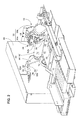
- the ingestion assembly 10 is shown in an operating position, i.e., for receiving the stack of sheet material 14, while, in Fig. 2 , the ingestion assembly 10 is shown in an idle position, i.e., pivoted upwardly to facilitate the removal of debris, jammed sheet material, and repair/maintenance.
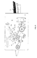
- the ingestion assembly 10 establishes the upper bounds of the ingestion area and includes: (i) a stone roller 26 disposed in opposed relation to the underlying drive roller 22, (ii) an idler roller 28, (iii) a housing assembly 30 for mounting the stone and idler rollers 26, 28, (iv) an adjustment mechanism 32 for varying a singulation gap between the drive and stone rollers 22, 26, and (v) an ingestion guide 34 disposed upstream of the drive and stone rollers 22, 26.
- the stone roller 26 is fixedly mounted about a first shaft 36 within the housing 26 while the idler roller 28 is mounted for rotation about a second shaft 38.
- the housing assembly 30 includes side plates 30a, 30b which are integrated by the shafts 36, 38 in addition to cross members (not viewable in Figs.
- the housing 30 includes a forward bell crank block 44 which is mounted between the side plates 30a, 30b about a third shaft 46.
- the bell crank block 44 mounts the stone roller 26 and serves to raise or lower the roller 26 by pivoting about the third shaft 46.
- a T-shaped handle 40 is mounted to an upper portion of the housing 30 and serves to facilitate rotation of the ingestion assembly 10 into and out of the operating and idle positions, seen in Figs. 1 and 2 , respectively.
- the adjustment mechanism 32 includes a threaded rod 42 disposed through an elongate aperture of the housing 30 which extends from the bell crank block 44 to an opening in an aft end of the housing 30.
- the threaded rod 42 is pin mounted to the bell crank block 44 at a forward end thereof and threadably engages an adjustment knob 46 at the aft end.
- the threaded rod 42 is biased forwardly by an internal coil spring 48 and may be displaced, i.e., forward and aft, by turning the adjustment knob 46, i.e., against the biasing force of the spring 48.
- the threaded rod 42 is displaced forwardly to rotate the bell crank block 44 in a counterclockwise direction about the shaft 46.
- the stone roller 26 is displaced downwardly to decrease the size of the singulation gap.
- Turning the adjustment knob 46 in the opposite direction causes the rod 42 to be drawn aft against the biasing force of the coil spring 48. Consequently, the bell crank block 44 rotates in a clockwise direction to lift the stone roller 26 and increase the singulation gap.
- the ingestion guide 34 improves the reliability of the singulating apparatus 10 by allowing only a few sheets, i.e., the lowermost sheets of the stack 14, to enter the ingestion area. More specifically, the ingestion guide 34 includes a moveable guide plate 52 which is pivotally mounted to a forward end of the housing 30, i.e., upstream of the stone roller 26.
- the guide plate 52 defines an inclined surface 52S (best seen in Figs. 1 and 2 ) which initiates shingling of the stack 14 ( Fig. 3 ) to prevent the stack 14 from wedging beneath, and lifting, the stone roller 26. With respect to the latter, it will be appreciated that forces tending to lift the stone roller 26 may increase the singulation gap and allow more than one sheet to pass under the stone roller 26.
- an arrangement 60 is provided for mounting the ingestion assembly 10 which (i) rigidly suspends the ingestion assembly 10 above the transport deck 12, i.e., the underlying conveyor belt(s)/roller(s) 18, 20, 22, 24, (i) permits rotation of the ingestion assembly from an operating position ( Fig. 1 ) to and idle position ( Fig. 2 ) to enable rapid access to the ingestion area, i.e., the area between the ingestion assembly 10 and the conveyor belt(s)/roller(s) 18, 20, 22, 24, and positively holds the ingestion assembly 10 in the operating and idle positions.
- the mounting arrangement 60 includes a radial bearing mount 62 and an over-center biasing mechanism 64.
- the radial bearing mount 62 provides a cantilevered support, i.e., to one side of the ingestion assembly, which provides rigidly and easy access to the underlying ingestion area.
- cantilevered means that the ingestion assembly 10 is suspended from a mounting structure which is rigidly affixed, at one end only, to a support structure.
- the over-center biasing mechanism 64 is coupled to the radial bearing mount 62 and forcibly holds the ingestion assembly 10 in each of the operational and idle positions.
- the radial bearing mount 62 couples the ingestion assembly 10 to a first support structure of the singulating apparatus, i.e., a vertical side wall structure 66 of the singulating apparatus.
- the radial bearing mount 62 includes first and second cylindrical members 70, 72, which are co-axially aligned about a pivot axis 70A which is substantially orthogonal to the feed path FP of the sheet material 14.
- the first cylindrical member 70 is mounted at a first end to the housing 30 of the ingestion assembly 10 and extends through a cylindrical orifice 720 in the second cylindrical member 72.
- the second cylindrical member 72 is mounted at one end to a first end to the vertical support structure 66 and is disposed over, or envelopes, the first cylindrical member 70.
- the radial bearing mount 62 furthermore, includes a pair of bearings 74 (only one is shown in Fig. 4 ) which are disposed between the outer and inner cylindrical surfaces walls 70S, 72S of the first and second cylindrical members 70, 72, and permit rotation of the first cylindrical member 70 relative to the second cylindrical member 72 about the pivot axis 70A.
- each bearing 74 may include a plurality of spherical balls 76 disposed in inner and outer bearing races 68a, 68b. While a ball-bearing assembly is described and is shown in Fig. 4 , the bearings 64 may be any roller, anti-friction or journal-type bearings, i.e., bearings which principally react radial loads and permit relative motion about an axis of rotation.
- the radial bearing mount 62 provides a high degree of bending stiffness along the pivot axis 70A for mounting the ingestion assembly 10 without flexure or deformation while in use.
- the radial bearing mount 62 is fabricated from a high stiffness metal such as stainless steel, aluminum or aluminum alloy, and has a diameter of between about one inch (1") to about one and one-half inches (1 1/2").
- the bearings 74 are spaced-apart, i.e., disposed at each end of the cylindrical members 70, 72 to provide bending moment stability along the pivot axis 70A.
- the radial bearing mount 62 may include a pair of drill bushings disposed in combination with a lapped fit pivot rod (not shown).
- the pivot rod extends the length of the pivot axis 70A and provides the requisite rigidity with minimal radial play to maintain the accuracy of the ingestion assembly 10, i.e., maintain the singulation gap between the drive and stone rollers 22, 26.
- the large separation distance between the drill bushings provides added journaling for bending moment stability.
- the over-center biasing mechanism 64 includes at least one telescoping strut 80 mounting to a second support structure of the singulating apparatus.
- the first and secondary support structures are integrated by a common vertical side wall structure 66, however, it should be appreciated that the stationary support structures may be distinct and separate elements of the singulating apparatus.
- the telescoping strut 80 is pivot mounted to the side wall structure 66 at one end thereof about a second pivot axis 80A and coupled to the radial bearing mount 62 at the other end.
- an actuation arm 82 is rigidly affixed to the second end of the first cylindrical member 70, i.e., an end which passes through the second cylindrical member 72 of the radial bearing mount 62 passing and the side-wall structure 66 of the singulating apparatus.
- the second end is also opposite the first end which mounts to the ingestion assembly 10.
- the over-center biasing mechanism 64 includes a pair of telescoping struts 80a, 80b disposed in juxtaposed relation (best seen in the perspective views of Fig. 1 and Fig. 2 ) and a single actuation arm 82.
- Each of the telescoping struts 80a, 80b includes a pneumatic or gas chamber 82 which is filled with a compressible fluid, e.g., air, under pressure.
- An extensible rod 84 is disposed in combination with the gas chamber and extends under the pressure applied by the fluid. More specifically, the pressurized fluid causes the rod 84 to fully extend and is compressed when the rod 84 is retracted.
- the rod 84 is fitted with a ringed-piston (not shown) which is sealed against the internal cylindrical walls of the gas cylinder 82 such that when the rod 84 is forced to retract, pressure builds within the fluid. Consequently, the forces which counteract the motion increases as a function of the displacement, in much the same way forces governing the reaction of a coil spring are a function of its displacement.
- the actuation arm 82 is pivotally mounted to each actuation rod 84 of the telescoping struts 80a, 80b at one end and rigidly affixed to the first cylindrical member 70 at the opposite end. Furthermore, the actuation arm 82 projects radially from the pivot axis 70A of the radial bearing mount.62. Moreover, the actuation arm 82 is connected to the first cylindrical member 70 on an opposite side of the support structure 66, i.e., opposite the ingestion assembly 10.
- the over-center mechanism 64 crosses a line of action LA which passes through the pivot axes 70A, 80A of the radial bearing mount 62 and the telescoping struts 80a, 80b, respectively.
- the telescoping struts 80a, 80b are initially compressed, i.e., causing the actuation rod 88 to compress the fluid within the gas chambers 86.
- the pressurized fluid forms a gas/air spring such that, when the actuation arm 82 crosses the line of action LA, the telescoping struts 80a, 80b of the over-center mechanism 64 expand to apply a biasing moment to the radial bearing mount 62. That is, the telescoping struts 80a, 80b apply a biasing moment about the pivot axis 70A through the actuation arm 82.
- the actuation arm 92 rotates until reaching a geometric or physical stop and the ingestion assembly 10 is forcibly urged into the operational position (shown in Fig. 1 ).
- the actuation arm 82 is urged against a stop pin 92, however, a stop disposed internally of the struts 80a, 80b, may be employed to urge the ingestion assembly 10 into its operational position.
- the ingestion assembly 10 is ready to singulate sheet material along the feed path and the singulation gap, i.e., the space between the drive and stone rollers 22, 26 (see Fig. 3 ), may then be controlled by the adjustment mechanism 32, described supra.
- the actuation arm 82 rotates until reaching a second stop, e.g., a second stop pin 94, and the ingestion assembly 10 is forcibly urged into the idle position.
- a second stop e.g., a second stop pin 94
- the ingestion assembly 10 is forcibly urged into the idle position.
- the various belt(s)/roller(s) of the singulating apparatus, 18, 20, 22, 24, 26, 28, may be inspected for repair and maintenance.
- the mounting arrangement 10 of the present invention includes an over-center mechanism 64 having a pair of juxtaposed telescoping struts 80a, 80b
- a single telescoping strut may be employed to apply the biasing moments about the radial bearing mount 62.
- the side-by-side struts 80 increase the biasing force applied to the radial bearing mount 62 without changing the geometry of the over-center mechanism 64 or increasing the profile dimension thereof.
- the described embodiment employs a side-wall structure 66 forming a solid vertical plane which is disposed to a side of, and vertically upward from, the transport deck 12. While a single planar structure may simplify manufacture and assembly, it will be appreciated that other support structures may be contemplated, e.g., a first structural support for the radial bearing mount 62 and a second structural support for mounting the over-center mechanism 64.
Landscapes
- Engineering & Computer Science (AREA)
- Mechanical Engineering (AREA)
- General Preparation And Processing Of Foods (AREA)
Abstract
An arrangement for mounting an ingestion assembly (10) within a singulating apparatus operative to singulate and convey sheet material (12) along a feed path. The mounting arrangement includes a radial bearing (62) pivotally mounting the ingestion assembly (10) to a stationary support structure (66) of the singulating apparatus. The radial bearing (62) is operative to pivot the singulating assembly (10) from an operating position to an idle position about a pivot axis which is substantially orthogonal to the feed path of the sheet material. The mounting arrangement also includes an over-center mechanism (64) disposed in combination with the radial bearing (62) for biasing the ingestion assembly (10) about the pivot axis such that the ingestion assembly (10) is forcibly held in each of the operating and idle positions. Optimum space utilization and ease of use is provided by the radial bearing (62) which cantilever mounts the ingestion assembly (10) to the singulating apparatus.
Description
- This invention relates to singulating sheet material/media, and more particularly, to a new and useful arrangement for mounting an ingestion assembly of a singulating module/apparatus.
- Material handling apparatus such as mailpiece inserters or mailing machines commonly employ rollers and/or belts for transporting and separating/singulating sheet material. In the context used herein, "sheet material" is used generically to describe any substantially flat, two-dimensional media such as sheets of paper, postcards, laminate, mailpieces, etc. Oftentimes, a combination of belts and rollers (fixed or rotating) are employed, e.g., a roller opposing a set of belts, to separate/singulate individual sheets from a stack of sheet material.
- A common singulating apparatus, used in a variety mailpiece inserters, employs one or more horizontal conveyor belts/rollers moving in one direction along a transport deck and at least one roller disposed above the belts to form a V-shaped ingestion area or throat between the rollers and the belt(s). In mailpiece inserters it is common to employ a stationary stone roller disposed a fixed distance above a conveyor belt/roller to define a gap which permits the passage of the lowermost sheet of material from a stack of sheet material. Alternatively, a drive roller may oppose the stone roller, immediately downstream of a conveyor belt to form the V-shaped throat for accepting sheet material from the conveyor belt. In other sheet handling apparatus, such as a mailing machine, a roller is similarly positioned above a conveyor belt/roller but is driven at a speed, or in a direction, which opposes the motion of the conveyor belt/roller to facilitate singulation of sheet of material. The roller(s), disposed above the driven belt/roller(s), are commonly mounted within a housing which includes an ingestion guide which is operative to prevent all but the lowermost sheets of a stack from approaching the ingestion throat, and an adjustment mechanism operative to define the singulation gap, i.e., the distance between the upper roller(s) and the underlying conveyor belt/roller, to accommodate sheets/mailpieces of various thickness. Hereinafter, the roller(s), housing, ingestion guide and adjustment mechanism will collectively be referred to as an "ingestion assembly" inasmuch as these elements are principally responsible for the ingestion/singulation of sheet material.
- A variety of factors associated with the geometry and arrangement of the ingestion assembly can be difficult to control and/or to optimize the effectiveness of the singulating apparatus. For example, the ingestion assembly roller(s) must be precisely aligned with the underlying drive belt(s)/roller(s) to ensure that sheet material is reliably singulated, i.e., without skewing or damage to the singulated sheets. Furthermore, the singulation gap must be reliably and accurately controlled/maintained to reliably singulate the sheet material. That is, the ingestion assembly must be rigidly mounted above the drive belt(s)/roller(s) to maintain the singulation gap without deviation/variation. Furthermore, the ingestion assembly must be removable/ detachable to access jammed sheet material from, or for the repair/maintenance of the underlying belt(s)/roller(s) of, the singulating apparatus.
- Prior art ingestion assemblies are typically mounted to the deck of the singulating apparatus by a rigid box structure which spans laterally across the feed path, i.e., from one side of the singulating apparatus to the other. The box structure is typically fabricated from a high strength steel or aluminum and comprises several, high stiffness, cross members which rigidly suspend the ingestion assembly above the conveyor belt(s)/roller(s). Furthermore, the box structure and deck include precise mating surfaces, i.e., machined surfaces, to ensure accurate placement of the ingestion assembly. Finally, the box structure is attached to the deck by large set-screws/knobs which enable the structure to be detached and reassembled should a jam occur, or when repair/maintenance of the ingestion assembly or underlying belt(s)/roller(s) is required.
- While this mounting arrangement provides the necessary rigidity, accuracy and flexibility to perform repair/maintenance, the box structure of the prior art is costly to fabricate and is cumbersome to assembly/reassemble, i.e., for such routine and, possibly frequent, activities associated with jam access and repair/maintenance.
- A need, therefore, exists for a mounting arrangement which rigidly and accurately positions the ingestion assembly above the underlying conveyor belt(s)/roller(s) of the singulating apparatus while facilitating access, repair and maintenance.
- The accompanying drawings illustrate presently preferred embodiments of the invention and, together with the general description given above and the detailed description given below serve to explain the principles of the invention. As shown throughout the drawings, like reference numerals designate like or corresponding parts.
-
Figure 1 is a partially broken-away perspective view of an arrangement for mounting an ingestion assembly to a singulating apparatus including a cantilevered radial bearing for pivotally mounting the ingestion assembly to a stationary support structure, e.g., a side wall structure, of the singulating apparatus. -
Figure 2 depicts a partially broken-away perspective view of the mounting arrangement wherein the ingestion assembly is pivoted upwardly and includes an over-center mechanism operative to bias the ingestion assembly into idle and operational positions. -
Figure 3 is a cross-sectional view taken substantially along line 3 - 3 ofFig. 1 wherein the ingestion assembly includes a stone roller disposed in opposed relation to an underlying drive roller, a housing assembly for fixedly mounting the stone roller, an adjustment mechanism for varying a singulation gap between the stone and drive rollers, and an ingestion guide disposed upstream of the stone and drive rollers. -
Figure 4 is a cross-sectional view taken substantially along line 4 - 4 ofFig. 1 depicting a view through the cantilevered radial bearing mount. -
Figure 5 is a rear profile view of the over-center mechanism wherein an extensible strut is adapted to apply a biasing moment about the pivot axis of the ingestion assembly to urge and retain the ingestion assembly into one of idle or operating positions. - An arrangement is provided for mounting an ingestion assembly within a singulating apparatus operative to singulate and convey sheet material along a feed path. The mounting arrangement includes a radial bearing pivotally mounting the ingestion assembly to a stationary support structure of the singulating apparatus. The radial bearing is operative to pivot the singulating assembly from an operating position to an idle position about a pivot axis which is substantially orthogonal to the feed path of the sheet material. The mounting arrangement also includes an over-center mechanism disposed in combination with the radial bearing for biasing the ingestion assembly about the pivot axis such that the ingestion assembly is forcibly held in each of the operating and idle positions. Optimum space utilization and ease of use is provided by the radial bearing which cantilever mounts the ingestion assembly to the singulating apparatus.
- The mounting arrangement of the present invention is described in the context of a singulating apparatus for mailing machines, though the invention is applicable to any singulation module/assembly for separating sheet material. For example, other sheet material handling apparatus which require separation of individual sheets from a stack of sheets include mailpiece sorting machines, copying and facsimile machines, etc. Furthermore, while the mounting arrangement is described in the context of an ingestion assembly having various components and assemblies for singulating sheet material, the ingestion assembly may employ any of variety of features which function to singulated/separate sheet material from a stack of material. For example, while the ingestion assembly includes a stone roller for singulating sheet material, other singulating rollers may be employed. For example, singulating rollers which rotate in a direction opposing the movement of the underlying conveyor belts, or in the same direction but at a reduced velocity relative thereto, may be employed.
- Referring to
Figs. 1 ,2 and3 , aningestion assembly 10 mounts above atransport deck 12 which conveys a stack of sheet material 14 (seeFig. 3 ) along a feed path FP. Thetransport deck 12 accepts thesheet material 14 from a plurality of input rollers 16 (seeFigs. 1 and2 ) upstream of thedeck 12 and includes a primaryinput conveyor belt 18, a secondaryinput conveyor belt 20 adjacent and downstream of the primaryinput conveyor belt 18, adrive roller 22 downstream of theinput conveyor belts away roller 24. InFigs. 1 and3 , theingestion assembly 10 is shown in an operating position, i.e., for receiving the stack ofsheet material 14, while, inFig. 2 , theingestion assembly 10 is shown in an idle position, i.e., pivoted upwardly to facilitate the removal of debris, jammed sheet material, and repair/maintenance. - The
ingestion assembly 10 establishes the upper bounds of the ingestion area and includes: (i) astone roller 26 disposed in opposed relation to theunderlying drive roller 22, (ii) anidler roller 28, (iii) ahousing assembly 30 for mounting the stone andidler rollers adjustment mechanism 32 for varying a singulation gap between the drive andstone rollers ingestion guide 34 disposed upstream of the drive andstone rollers stone roller 26 is fixedly mounted about a first shaft 36 within thehousing 26 while theidler roller 28 is mounted for rotation about a second shaft 38. Thehousing assembly 30 includesside plates Figs. 1 through 3 ) which provide additional structural integrity. Additionally, thehousing 30 includes a forwardbell crank block 44 which is mounted between theside plates third shaft 46. Thebell crank block 44 mounts thestone roller 26 and serves to raise or lower theroller 26 by pivoting about thethird shaft 46. A T-shaped handle 40 is mounted to an upper portion of thehousing 30 and serves to facilitate rotation of theingestion assembly 10 into and out of the operating and idle positions, seen inFigs. 1 and2 , respectively. - In
Fig. 3 , theadjustment mechanism 32 includes a threadedrod 42 disposed through an elongate aperture of thehousing 30 which extends from thebell crank block 44 to an opening in an aft end of thehousing 30. The threadedrod 42 is pin mounted to thebell crank block 44 at a forward end thereof and threadably engages anadjustment knob 46 at the aft end. Furthermore, the threadedrod 42 is biased forwardly by aninternal coil spring 48 and may be displaced, i.e., forward and aft, by turning theadjustment knob 46, i.e., against the biasing force of thespring 48. By turning theknob 46 in one direction, the threadedrod 42 is displaced forwardly to rotate thebell crank block 44 in a counterclockwise direction about theshaft 46. As a result, thestone roller 26 is displaced downwardly to decrease the size of the singulation gap. Turning theadjustment knob 46 in the opposite direction causes therod 42 to be drawn aft against the biasing force of thecoil spring 48. Consequently, thebell crank block 44 rotates in a clockwise direction to lift thestone roller 26 and increase the singulation gap. - The
ingestion guide 34 improves the reliability of thesingulating apparatus 10 by allowing only a few sheets, i.e., the lowermost sheets of thestack 14, to enter the ingestion area. More specifically, theingestion guide 34 includes amoveable guide plate 52 which is pivotally mounted to a forward end of thehousing 30, i.e., upstream of thestone roller 26. Theguide plate 52 defines aninclined surface 52S (best seen inFigs. 1 and2 ) which initiates shingling of the stack 14 (Fig. 3 ) to prevent thestack 14 from wedging beneath, and lifting, thestone roller 26. With respect to the latter, it will be appreciated that forces tending to lift thestone roller 26 may increase the singulation gap and allow more than one sheet to pass under thestone roller 26. - According to the present invention, an
arrangement 60 is provided for mounting theingestion assembly 10 which (i) rigidly suspends theingestion assembly 10 above thetransport deck 12, i.e., the underlying conveyor belt(s)/roller(s) 18, 20, 22, 24, (i) permits rotation of the ingestion assembly from an operating position (Fig. 1 ) to and idle position (Fig. 2 ) to enable rapid access to the ingestion area, i.e., the area between theingestion assembly 10 and the conveyor belt(s)/roller(s) 18, 20, 22, 24, and positively holds theingestion assembly 10 in the operating and idle positions. More specifically, themounting arrangement 60 includes aradial bearing mount 62 and an over-centerbiasing mechanism 64. Theradial bearing mount 62 provides a cantilevered support, i.e., to one side of the ingestion assembly, which provides rigidly and easy access to the underlying ingestion area. In the context used herein, the term "cantilevered" means that theingestion assembly 10 is suspended from a mounting structure which is rigidly affixed, at one end only, to a support structure. The over-centerbiasing mechanism 64 is coupled to theradial bearing mount 62 and forcibly holds theingestion assembly 10 in each of the operational and idle positions. Each of these assemblies/components will be described in greater detail in subsequent paragraphs. - In
Figs. 1 through 4 , theradial bearing mount 62 couples theingestion assembly 10 to a first support structure of the singulating apparatus, i.e., a verticalside wall structure 66 of the singulating apparatus. InFigs. 3 and 4 , the radial bearing mount 62 includes first and secondcylindrical members pivot axis 70A which is substantially orthogonal to the feed path FP of thesheet material 14. The firstcylindrical member 70 is mounted at a first end to thehousing 30 of theingestion assembly 10 and extends through acylindrical orifice 720 in the secondcylindrical member 72. The secondcylindrical member 72 is mounted at one end to a first end to thevertical support structure 66 and is disposed over, or envelopes, the firstcylindrical member 70. - The
radial bearing mount 62, furthermore, includes a pair of bearings 74 (only one is shown inFig. 4 ) which are disposed between the outer and innercylindrical surfaces walls cylindrical members cylindrical member 70 relative to the secondcylindrical member 72 about thepivot axis 70A. In the illustrated embodiment, each bearing 74 may include a plurality of spherical balls 76 disposed in inner and outer bearing races 68a, 68b. While a ball-bearing assembly is described and is shown inFig. 4 , thebearings 64 may be any roller, anti-friction or journal-type bearings, i.e., bearings which principally react radial loads and permit relative motion about an axis of rotation. - The radial bearing mount 62 provides a high degree of bending stiffness along the
pivot axis 70A for mounting theingestion assembly 10 without flexure or deformation while in use. In the described embodiment, the radial bearing mount 62 is fabricated from a high stiffness metal such as stainless steel, aluminum or aluminum alloy, and has a diameter of between about one inch (1") to about one and one-half inches (1 1/2"). Furthermore, thebearings 74 are spaced-apart, i.e., disposed at each end of thecylindrical members pivot axis 70A. - In another embodiment of the invention, the radial bearing mount 62 may include a pair of drill bushings disposed in combination with a lapped fit pivot rod (not shown). The pivot rod extends the length of the
pivot axis 70A and provides the requisite rigidity with minimal radial play to maintain the accuracy of theingestion assembly 10, i.e., maintain the singulation gap between the drive andstone rollers - In
Figs. 1 ,2 , and5 , theover-center biasing mechanism 64 includes at least one telescoping strut 80 mounting to a second support structure of the singulating apparatus. In the described embodiment, the first and secondary support structures are integrated by a common verticalside wall structure 66, however, it should be appreciated that the stationary support structures may be distinct and separate elements of the singulating apparatus. The telescoping strut 80 is pivot mounted to theside wall structure 66 at one end thereof about asecond pivot axis 80A and coupled to the radial bearing mount 62 at the other end. In the described embodiment, an actuation arm 82 is rigidly affixed to the second end of the firstcylindrical member 70, i.e., an end which passes through the secondcylindrical member 72 of the radial bearing mount 62 passing and the side-wall structure 66 of the singulating apparatus. The second end is also opposite the first end which mounts to theingestion assembly 10. - In the described embodiment, the
over-center biasing mechanism 64 includes a pair oftelescoping struts Fig. 1 andFig. 2 ) and a single actuation arm 82. Each of the telescoping struts 80a, 80b includes a pneumatic or gas chamber 82 which is filled with a compressible fluid, e.g., air, under pressure. An extensible rod 84 is disposed in combination with the gas chamber and extends under the pressure applied by the fluid. More specifically, the pressurized fluid causes the rod 84 to fully extend and is compressed when the rod 84 is retracted. With respect to the latter, the rod 84 is fitted with a ringed-piston (not shown) which is sealed against the internal cylindrical walls of the gas cylinder 82 such that when the rod 84 is forced to retract, pressure builds within the fluid. Consequently, the forces which counteract the motion increases as a function of the displacement, in much the same way forces governing the reaction of a coil spring are a function of its displacement. - The actuation arm 82 is pivotally mounted to each actuation rod 84 of the telescoping struts 80a, 80b at one end and rigidly affixed to the first
cylindrical member 70 at the opposite end. Furthermore, the actuation arm 82 projects radially from thepivot axis 70A of the radial bearing mount.62. Moreover, the actuation arm 82 is connected to the firstcylindrical member 70 on an opposite side of thesupport structure 66, i.e., opposite theingestion assembly 10. - In operation, when the singulating apparatus is prepared to feed
sheet material 14, an operator rotates the handle 40 (affixed to thehousing 30 of the ingestion assembly 10) downwardly to rotationally displace theingestion assembly 10 into the operating position (shown inFig. 1 ). Rotation of theingestion assembly 10 effects rotation of the firstcylindrical member 70 about thepivot axis 70A and causes the actuation arm 82 of theover-center mechanism 64 to rotate through an angle θ (seeFig. 5 ). In the described embodiment, the angle θ is about forty-five degrees (45°), however, the total angular displacement may increase or decrease depending upon the amount of desired access beneath theingestion assembly 10. As the actuation arm 82 is displaced in a clockwise direction CL about thepivot axis 70A, theover-center mechanism 64 crosses a line of action LA which passes through the pivot axes 70A, 80A of theradial bearing mount 62 and the telescoping struts 80a, 80b, respectively. During rotational displacement, the telescoping struts 80a, 80b are initially compressed, i.e., causing theactuation rod 88 to compress the fluid within thegas chambers 86. The pressurized fluid forms a gas/air spring such that, when the actuation arm 82 crosses the line of action LA, the telescoping struts 80a, 80b of theover-center mechanism 64 expand to apply a biasing moment to theradial bearing mount 62. That is, the telescoping struts 80a, 80b apply a biasing moment about thepivot axis 70A through the actuation arm 82. As a consequence, the actuation arm 92 rotates until reaching a geometric or physical stop and theingestion assembly 10 is forcibly urged into the operational position (shown inFig. 1 ). In the described embodiment, the actuation arm 82 is urged against a stop pin 92, however, a stop disposed internally of thestruts ingestion assembly 10 into its operational position. In the operational position, theingestion assembly 10 is ready to singulate sheet material along the feed path and the singulation gap, i.e., the space between the drive andstone rollers 22, 26 (seeFig. 3 ), may then be controlled by theadjustment mechanism 32, described supra. - When the singulating apparatus is opened for jam access, repair or maintenance, an operator rotates the
handle 40 upwardly to rotationally displace theingestion assembly 10 into the idle position (shown inFig. 2 ). Rotation of theingestion assembly 10 effects rotation of the firstcylindrical member 70 in a counterclockwise direction CC about thepivot axis 70A. As a result, theover-center mechanism 64 crosses the line of action LA to, once again, compress and pressurize the fluid within the telescoping struts 80a, 80b. Similar to the motion described above, the telescoping struts 80a, 80b expand to apply a biasing moment to theradial bearing mount 62. As a consequence, the actuation arm 82 rotates until reaching a second stop, e.g., asecond stop pin 94, and theingestion assembly 10 is forcibly urged into the idle position. In the idle position, areas prone to sheet material jams may be accessed and the various belt(s)/roller(s) of the singulating apparatus, 18, 20, 22, 24, 26, 28, may be inspected for repair and maintenance. - Although the invention has been described with respect to a preferred embodiment thereof, it will be understood by those skilled in the art that the foregoing and various other changes, omissions and deviations in the form and detail thereof may be made without departing from the scope of this invention. For example, while the mounting
arrangement 10 of the present invention includes anover-center mechanism 64 having a pair of juxtaposed telescoping struts 80a, 80b, a single telescoping strut may be employed to apply the biasing moments about theradial bearing mount 62. In the described embodiment, the side-by-side struts 80 increase the biasing force applied to the radial bearing mount 62 without changing the geometry of theover-center mechanism 64 or increasing the profile dimension thereof. Furthermore, the described embodiment employs a side-wall structure 66 forming a solid vertical plane which is disposed to a side of, and vertically upward from, thetransport deck 12. While a single planar structure may simplify manufacture and assembly, it will be appreciated that other support structures may be contemplated, e.g., a first structural support for theradial bearing mount 62 and a second structural support for mounting theover-center mechanism 64.
Claims (14)
- A mounting arrangement for mounting an ingestion assembly (10) within a singulating apparatus, the singulating apparatus operative to singulate sheet material (14) which is fed along a feed path (FP), the mounting arrangement comprising:a radial bearing mount (62) connecting the ingestion assembly to a support structure (66) of the singulating apparatus, the radial bearing mount (62) pivotally mounting about a pivot axis (70A) substantially orthogonal to the sheet material feed path and operative to pivot the ingestion assembly (10) from an operating position to an idle position; andan over-center mechanism (64) coupled to the radial bearing mount (62) for biasing the ingestion assembly (10) about the pivot axis (70A) such that the ingestion assembly (10) is forcibly held in each of the operating and idle positions.
- The mounting arrangement according to Claim 1, wherein the over-center mechanism (64) includes at least one telescoping strut (80) pivotally mounting about a pivot axis (80A) to a support structure (66) of the singulating apparatus, the over-center mechanism (64) defining a line of action passing through the pivot axes of the radial bearing mount (62) and the at least one telescoping strut (80), and projecting radially from the pivot axis (70A) of the radial bearing mount (62), the telescoping strut (80) operative to extend when disposed to either side of the line of action and apply a biasing moment about the pivot axis of the radial bearing mount (62) when the strut is disposed to either side of the line of action.
- The mounting arrangement according to Claim 2, wherein the telescoping strut (80) is an extensible strut having a gas chamber (86) and an actuation rod (84), the gas chamber (86) having a pressurized fluid therein and operative to bias the actuation rod (84) as a function of the magnitude of pressure within the pressurized fluid.
- The mounting arrangement according to Claim 3, wherein the radial bearing mount (62) is a cantilever mount.
- The mounting arrangement according to Claim 2 wherein the over-center mechanism (64) includes a pair of extensible struts (80a, 80b) disposed in juxtaposed relation.
- The mounting arrangement according to Claim 5, wherein each of the telescoping struts (80a, 80b) is an extensible strut having a gas chamber (86) and an actuation rod (84), the gas chamber having a pressurized fluid therein and operative to bias the actuation rod (84) as a function of the magnitude of pressure within the pressurized fluid.
- The mounting arrangement according to any one of Claims 1 to 6, wherein the radial bearing mount (62) is a cantilever mount.
- The mounting arrangement according to Claim 7, wherein the singulating apparatus includes a side-wall structure (66) and wherein the cantilever mount is affixed at one end to the side-wall structure and at the other end to a side of the ingestion assembly.
- A method for mounting an ingestion assembly (10) within a singulating apparatus, the singulating apparatus operative to singulate sheet material (12) which is fed along a feed path, the method comprising the steps of:connecting the ingestion assembly (10) to a support structure (66) of the singulating apparatus by a radial bearing mount (62), the radial bearing mount (62) pivotally mounting about a pivot axis (70A) substantially orthogonal to the sheet material feed path and operative to pivot the ingestion assembly (10) from an operating position to an idle position; andbiasing the ingestion assembly (10) about the pivot axis such that the ingestion assembly is forcibly held in each of the operating and idle positions.
- The method according to Claim 9, wherein the step of connecting the ingestion assembly (10) to the support structure (66) includes the step of mounting the ingestion assembly (10) to the support structure by a cantilever mount.
- The method according to Claim 9 or 10, wherein the step of biasing the ingestion assembly (10) includes the step of providing an over-center mechanism (64) having at least one telescoping strut (80) pivotally mounting about a pivot axis (80A) to a support structure (66) of the singulating apparatus, the over-center mechanism (64) defining a line of action projecting radially from the pivot axis (80A) and passing through the pivot axes of the radial bearing mount (62) and the at least one telescoping strut (80), and causing the telescoping strut (80) to extend when disposed to either side of the line of action and apply a biasing moment about the pivot axis of the radial bearing mount (62) when the strut is disposed to either side of the line of action.
- The method according to Claim 11, wherein the step of causing the telescoping strut (80) to extend includes the steps of: providing an extensible strut having a gas chamber (86) and an actuation rod (84), pressurizing the gas chamber with a compressible fluid and biasing the actuation rod (84) as a function of the magnitude of pressure within the pressurized fluid.
- The method according to Claim 11 or 12, wherein the step of providing an over-center mechanism (64) having at least one telescoping strut includes the step of providing a pair of telescoping struts (80a, 80b) disposed in juxtaposed relation.
- The method according to Claim 13, wherein the step of providing a pair of telescoping struts (80a, 80b) includes the steps of providing a pair of extensible struts each having a gas chamber (86) and an actuation rod (84), pressurizing the gas chamber of each with a compressible fluid and biasing the actuation rods (84) as a function of the magnitude of pressure within the pressurized fluid.
Applications Claiming Priority (1)
| Application Number | Priority Date | Filing Date | Title |
|---|---|---|---|
| US12/276,534 US7934715B2 (en) | 2008-11-24 | 2008-11-24 | Arrangement for mounting an ingestion assembly of a singulating apparatus |
Publications (1)
| Publication Number | Publication Date |
|---|---|
| EP2189402A2 true EP2189402A2 (en) | 2010-05-26 |
Family
ID=41349249
Family Applications (1)
| Application Number | Title | Priority Date | Filing Date |
|---|---|---|---|
| EP09173015A Withdrawn EP2189402A2 (en) | 2008-11-24 | 2009-10-14 | Arrangement for mounting an ingestion assembly of a singulating apparatus |
Country Status (2)
| Country | Link |
|---|---|
| US (1) | US7934715B2 (en) |
| EP (1) | EP2189402A2 (en) |
Families Citing this family (2)
| Publication number | Priority date | Publication date | Assignee | Title |
|---|---|---|---|---|
| DE102009039067A1 (en) * | 2009-08-27 | 2011-03-10 | Siemens Aktiengesellschaft | Device and method for separating flat objects by means of two laterally offset singler |
| DE202015102333U1 (en) * | 2015-05-07 | 2015-05-20 | Francotyp-Postalia Gmbh | Good processing device for creating and separating flat goods |
Family Cites Families (5)
| Publication number | Priority date | Publication date | Assignee | Title |
|---|---|---|---|---|
| DE4122329C2 (en) * | 1991-07-05 | 1995-08-10 | Heidelberger Druckmasch Ag | Device for feeding sheets and their further processing in sheet-fed rotary printing machines |
| JP3863381B2 (en) * | 2000-04-28 | 2006-12-27 | 京セラミタ株式会社 | Document transport apparatus and image forming machine |
| FR2833934B1 (en) * | 2001-12-24 | 2004-07-09 | Neopost Ind | MAIL ARTICLE SELECTOR DEVICE |
| US6779792B2 (en) * | 2002-10-28 | 2004-08-24 | Pitney Bowes Inc. | Jam release mechanism for a mailing machine |
| US7789387B2 (en) * | 2008-12-22 | 2010-09-07 | Pitney Bowes Inc. | Roller assembly for feeding stacked sheet material |
-
2008
- 2008-11-24 US US12/276,534 patent/US7934715B2/en active Active
-
2009
- 2009-10-14 EP EP09173015A patent/EP2189402A2/en not_active Withdrawn
Also Published As
| Publication number | Publication date |
|---|---|
| US7934715B2 (en) | 2011-05-03 |
| US20100127449A1 (en) | 2010-05-27 |
Similar Documents
| Publication | Publication Date | Title |
|---|---|---|
| US6217020B1 (en) | Method and apparatus for detecting proper mailpiece position for feeding | |
| EP2439156B1 (en) | Sheet separating mechanism | |
| CA2249482C (en) | A nudger for a mail handling system | |
| US20090008859A1 (en) | Multi-segment weight measurement apparatus and method for processing sheet material | |
| US7934715B2 (en) | Arrangement for mounting an ingestion assembly of a singulating apparatus | |
| US7841594B2 (en) | Apparatus for altering the orientation and/or direction of sheet material in mailpiece fabrication systems | |
| NO20160721A1 (en) | Goods processing apparatus to place and singularize flat goods and method | |
| CA2100373A1 (en) | Single pass pressure sealer for planar or nested media | |
| US7601923B2 (en) | Parallel path weight measurement system for sheet handling devices | |
| US8353510B2 (en) | Variable media feed system and printhead apparatus | |
| US6585251B2 (en) | Articulating separator | |
| CA2240602C (en) | Sorting device in a conveyor of plate-like workpieces | |
| CN103662941A (en) | Sheet storing apparatus, post-processing apparatus and image forming system having the same | |
| US7789387B2 (en) | Roller assembly for feeding stacked sheet material | |
| EP1918231A2 (en) | Singulation module/belt for separating sheet material | |
| US7810687B2 (en) | Self-aligning nip for web feeding mechanism | |
| US8998201B2 (en) | Sheet retention device | |
| EP1946939B1 (en) | Thick product feeder | |
| EP2149524B1 (en) | Vacuum Sheet Feeder | |
| CN212639275U (en) | Card paper material feeding unit | |
| EP1894869B1 (en) | Sheet material inverter | |
| US8038149B2 (en) | Alignment/registration and conveyance apparatus | |
| US5641159A (en) | Synchronizing roller arrangement for transporting sheets into a sheet-processing machine | |
| CN112573275A (en) | Paper discharge device, control method for paper discharge device, processing device, and recording system | |
| CN217024602U (en) | Paper separating mechanism and paper feeding equipment with same |
Legal Events
| Date | Code | Title | Description |
|---|---|---|---|
| PUAI | Public reference made under article 153(3) epc to a published international application that has entered the european phase |
Free format text: ORIGINAL CODE: 0009012 |
|
| AK | Designated contracting states |
Kind code of ref document: A2 Designated state(s): AT BE BG CH CY CZ DE DK EE ES FI FR GB GR HR HU IE IS IT LI LT LU LV MC MK MT NL NO PL PT RO SE SI SK SM TR |
|
| AX | Request for extension of the european patent |
Extension state: AL BA RS |
|
| STAA | Information on the status of an ep patent application or granted ep patent |
Free format text: STATUS: THE APPLICATION HAS BEEN WITHDRAWN |
|
| 18W | Application withdrawn |
Effective date: 20110317 |