EP2189128A1 - Medical device system - Google Patents
Medical device system Download PDFInfo
- Publication number
- EP2189128A1 EP2189128A1 EP08740051A EP08740051A EP2189128A1 EP 2189128 A1 EP2189128 A1 EP 2189128A1 EP 08740051 A EP08740051 A EP 08740051A EP 08740051 A EP08740051 A EP 08740051A EP 2189128 A1 EP2189128 A1 EP 2189128A1
- Authority
- EP
- European Patent Office
- Prior art keywords
- medical device
- warning
- electrode
- inter
- contact
- Prior art date
- Legal status (The legal status is an assumption and is not a legal conclusion. Google has not performed a legal analysis and makes no representation as to the accuracy of the status listed.)
- Granted
Links
Images





Classifications
-
- A—HUMAN NECESSITIES
- A61—MEDICAL OR VETERINARY SCIENCE; HYGIENE
- A61B—DIAGNOSIS; SURGERY; IDENTIFICATION
- A61B1/00—Instruments for performing medical examinations of the interior of cavities or tubes of the body by visual or photographical inspection, e.g. endoscopes; Illuminating arrangements therefor
- A61B1/00147—Holding or positioning arrangements
-
- A—HUMAN NECESSITIES
- A61—MEDICAL OR VETERINARY SCIENCE; HYGIENE
- A61B—DIAGNOSIS; SURGERY; IDENTIFICATION
- A61B1/00—Instruments for performing medical examinations of the interior of cavities or tubes of the body by visual or photographical inspection, e.g. endoscopes; Illuminating arrangements therefor
- A61B1/00064—Constructional details of the endoscope body
- A61B1/00071—Insertion part of the endoscope body
- A61B1/0008—Insertion part of the endoscope body characterised by distal tip features
- A61B1/00097—Sensors
-
- A—HUMAN NECESSITIES
- A61—MEDICAL OR VETERINARY SCIENCE; HYGIENE
- A61B—DIAGNOSIS; SURGERY; IDENTIFICATION
- A61B1/00—Instruments for performing medical examinations of the interior of cavities or tubes of the body by visual or photographical inspection, e.g. endoscopes; Illuminating arrangements therefor
- A61B1/005—Flexible endoscopes
-
- A—HUMAN NECESSITIES
- A61—MEDICAL OR VETERINARY SCIENCE; HYGIENE
- A61B—DIAGNOSIS; SURGERY; IDENTIFICATION
- A61B34/00—Computer-aided surgery; Manipulators or robots specially adapted for use in surgery
- A61B34/30—Surgical robots
-
- A—HUMAN NECESSITIES
- A61—MEDICAL OR VETERINARY SCIENCE; HYGIENE
- A61B—DIAGNOSIS; SURGERY; IDENTIFICATION
- A61B34/00—Computer-aided surgery; Manipulators or robots specially adapted for use in surgery
- A61B34/70—Manipulators specially adapted for use in surgery
-
- A—HUMAN NECESSITIES
- A61—MEDICAL OR VETERINARY SCIENCE; HYGIENE
- A61B—DIAGNOSIS; SURGERY; IDENTIFICATION
- A61B5/00—Measuring for diagnostic purposes; Identification of persons
- A61B5/05—Detecting, measuring or recording for diagnosis by means of electric currents or magnetic fields; Measuring using microwaves or radio waves
- A61B5/053—Measuring electrical impedance or conductance of a portion of the body
- A61B5/0538—Measuring electrical impedance or conductance of a portion of the body invasively, e.g. using a catheter
-
- A—HUMAN NECESSITIES
- A61—MEDICAL OR VETERINARY SCIENCE; HYGIENE
- A61B—DIAGNOSIS; SURGERY; IDENTIFICATION
- A61B5/00—Measuring for diagnostic purposes; Identification of persons
- A61B5/68—Arrangements of detecting, measuring or recording means, e.g. sensors, in relation to patient
- A61B5/6846—Arrangements of detecting, measuring or recording means, e.g. sensors, in relation to patient specially adapted to be brought in contact with an internal body part, i.e. invasive
- A61B5/6885—Monitoring or controlling sensor contact pressure
-
- A—HUMAN NECESSITIES
- A61—MEDICAL OR VETERINARY SCIENCE; HYGIENE
- A61B—DIAGNOSIS; SURGERY; IDENTIFICATION
- A61B1/00—Instruments for performing medical examinations of the interior of cavities or tubes of the body by visual or photographical inspection, e.g. endoscopes; Illuminating arrangements therefor
- A61B1/012—Instruments for performing medical examinations of the interior of cavities or tubes of the body by visual or photographical inspection, e.g. endoscopes; Illuminating arrangements therefor characterised by internal passages or accessories therefor
- A61B1/018—Instruments for performing medical examinations of the interior of cavities or tubes of the body by visual or photographical inspection, e.g. endoscopes; Illuminating arrangements therefor characterised by internal passages or accessories therefor for receiving instruments
-
- A—HUMAN NECESSITIES
- A61—MEDICAL OR VETERINARY SCIENCE; HYGIENE
- A61B—DIAGNOSIS; SURGERY; IDENTIFICATION
- A61B17/00—Surgical instruments, devices or methods
- A61B2017/00017—Electrical control of surgical instruments
- A61B2017/00115—Electrical control of surgical instruments with audible or visual output
- A61B2017/00119—Electrical control of surgical instruments with audible or visual output alarm; indicating an abnormal situation
-
- A—HUMAN NECESSITIES
- A61—MEDICAL OR VETERINARY SCIENCE; HYGIENE
- A61B—DIAGNOSIS; SURGERY; IDENTIFICATION
- A61B18/00—Surgical instruments, devices or methods for transferring non-mechanical forms of energy to or from the body
- A61B2018/00636—Sensing and controlling the application of energy
- A61B2018/00773—Sensed parameters
- A61B2018/00875—Resistance or impedance
-
- A—HUMAN NECESSITIES
- A61—MEDICAL OR VETERINARY SCIENCE; HYGIENE
- A61B—DIAGNOSIS; SURGERY; IDENTIFICATION
- A61B18/00—Surgical instruments, devices or methods for transferring non-mechanical forms of energy to or from the body
- A61B2018/00636—Sensing and controlling the application of energy
- A61B2018/00898—Alarms or notifications created in response to an abnormal condition
-
- A—HUMAN NECESSITIES
- A61—MEDICAL OR VETERINARY SCIENCE; HYGIENE
- A61B—DIAGNOSIS; SURGERY; IDENTIFICATION
- A61B34/00—Computer-aided surgery; Manipulators or robots specially adapted for use in surgery
- A61B34/30—Surgical robots
- A61B2034/301—Surgical robots for introducing or steering flexible instruments inserted into the body, e.g. catheters or endoscopes
-
- A—HUMAN NECESSITIES
- A61—MEDICAL OR VETERINARY SCIENCE; HYGIENE
- A61B—DIAGNOSIS; SURGERY; IDENTIFICATION
- A61B90/00—Instruments, implements or accessories specially adapted for surgery or diagnosis and not covered by any of the groups A61B1/00 - A61B50/00, e.g. for luxation treatment or for protecting wound edges
- A61B90/06—Measuring instruments not otherwise provided for
- A61B2090/064—Measuring instruments not otherwise provided for for measuring force, pressure or mechanical tension
- A61B2090/065—Measuring instruments not otherwise provided for for measuring force, pressure or mechanical tension for measuring contact or contact pressure
Definitions
- the present invention relates to a medical device system, and, more particularly to a medical device system having plural medical devices that are likely to come into contact with one another in a body cavity.
- laparoscopic surgical operation is an operation performed by using a medical device inserted through a small dissected opening of the skin of a patient.
- a medical device having an elongated insertion portion is inserted through a trocar (a mantle tube) pierced into an epigastria region while the region being observed by an endoscope and the operation is performed.
- Japanese Patent Application Laid-Open Publication No. 2004-81277 discloses an endoscope added with a function for detecting, when a surgical device used for the endoscopic surgical operation comes into contact with the endoscope, the contact using an arranged sensor and avoiding the contact.
- Japanese Patent Application Laid-Open Publication No. 2004-89591 discloses a medical device having an electric manipulator in the endoscopic surgical operation.
- the sensor for detecting the contact between the surgical device and the endoscope disclosed in Japanese Patent Application Laid-Open Publication 2004-81277 is a gyro sensor and detects the contact as angular velocity. Therefore, structure and control of a detection system are complicated. When the gyro sensor is disposed in the surgical device used for the endoscopic surgical operation, it is likely that an insertion portion is increased in thickness.
- medical devices located at distal ends of two manipulators are medical devices to which positive voltage is alternately applied.
- a purpose of this voltage application is to bum and stanch a diseased part.
- the electrically-driven medical device also has a problem that, even if contact occurs among the medical devices, a surgeon is late in noticing the occurrence of the contact.
- the present invention can provide a medical device system that can detect, at an early stage, contact among medical devices used in a body cavity and prevent breakage and the like of the medical devices.
- a medical device system includes: first and second medical devices, each of which is used in a body cavity and surfaces of which have conductivity; a first electrode electrically connected to the surface of the first medical device; a second electrode electrically connected to the surface of the second medical device; resistance measuring means for measuring an inter-device electric resistance value as electric resistance between the first electrode and the second electrode; threshold storing means for storing an inter-device resistance threshold as a lower limit value of the inter-device resistance value; determining means for determining, when the inter-device resistance value is lower than the inter-device resistance threshold, that the first medical device and the second medical device have come into contact with each other; and warning generating means for generating a warning when the determining means determines that the first medical device and the second medical device have come into contact with each other.
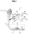
- Fig. 1 is a configuration diagram for explaining a medical device system 1 according to a first embodiment of the present invention.
- the medical device system 1 includes an endoscope 10 including an observation lens 11 at a distal end thereof, a first medical device 21, a second medical device 22, driving means 42a and 42b, a control device 30, and input means 40a and 40b.
- the first medical device 21 and the second medical device 22 project from a distal end portion of the endoscope 10 inserted in vivo and are used for performing an operation on a living tissue VA in body cavity V.
- the first medical device 21 and the second medical device 22 are active medical devices that are electrically driven with input information from the respective manual-operation input means 40a and 40b transmitted to the respective driving means 42a and 42b via the control device 30.
- the manual-operation input means 40a and 40b are input means for converting three-dimensional motion of operation arms of an input device by a surgeon, i.e., physical displacement of the input device into an electric signal.
- the respective manual-operation input means are devices adjusted to the respective medical devices. For example, when the medical devices have two joints, the manual-operation input means also have two joints. Therefore, the surgeon can apply desired operation to the medical devices by operating the manual-operation input means. When a motion amount of the medical devices is set small with respect to an actual physical displacement amount of the operation arms of the manual-operation input means, the surgeon can easily realize extremely fine motion of the medical devices.
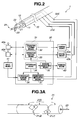
- Fig. 2 is a block diagram of the medical device system 1 according to the present embodiment.
- the first medical device 21 and the second medical device 22 project from forceps holes 12 at the distal end portion of the endoscope 10.
- Surfaces of the medical devices have conductivity. This does not mean that the medical devices themselves do not always need to be made of a conductive material, for example, SUS and the surfaces of the medical devices at least have to be coated with a material having conductivity.
- the medical device system 1 includes a first electrode 21E electrically connected to the surface of the first medical device 21 by an electric wire and a second electrode 22E electrically connected to the surface of the second medical device 22 by an electric wire. Electric resistance between the first electrode 21E and the second electrode 22E, i.e., an inter-device electric resistance value is measured by resistance measuring means 37.
- the first medical device 21 and the second medical device 22 respectively have a knife arm 23 and hand arms 24.
- the first medical device 21 and the second medical device 22 are active medical devices driven by the driving means 42a and 42b according to instructions from the respective input means 40a and 40b via the control means 31.
- the control device 30 includes threshold storing means 36 for storing a threshold of inter-device resistance inputted from the input means 41, determining means 34 for determining whether the inter-device resistance is smaller than the threshold of the inter-device resistance stored in the threshold storing means 36, and warning generating means 35 for generating a warning on the basis of the determination of the determining means 34.
- the warning generated by the warning generating means 35 is transmitted to the surgeon by publicly-known warning such as sound, light, or vibration of warning means 43.
- the warning generated by the warning generating means 35 is transmitted to the control means 31 as an electric signal.
- the control means 31 controls to perform contact avoiding operation explained later.
- the manual-operation input means 40a and 40b are different depending on a type of an electric driving mechanism for medical devices.
- manual-operation input means for a biaxially operating medical device a normal joystick can be used.
- the manual operation input means called operation arms for converting three-dimensional motion of hands of a surgeon to front and back, up and down, and left and right into an electric signal is used.
- the motion of the hands of the surgeon is detected by sensors or the like disposed in the manual-operation input means. Information concerning physical displacement of the manual-operation input means is converted into an electric signal.
- the manual-operation input means 40a and 40b themselves have not-shown driving mechanisms.
- the manual-operation input means 40a and 40b having the driving mechanisms contrary to converting the motion of the hands of the surgeon into an electric signal, it is possible to generate force in an opposite direction against operation of the operation arms or the like by the motion of the hands of the surgeon to restrict the motion of the hands of the surgeon or change displacement of the operation arms or the like according to motion of the active medical devices unrelated to the surgeon as explained later.
- the control device 30 may have operation storing means 32.
- the operation storing means 32 stores, together with elapsed time, operation of the first medical device 21 and the second medical device 22 by the operation control means 33 and displacement of the manual-operation input means 40a and 40b.
- Fig. 3A is a perspective view of the first medical device 21 and Fig. 3B is a sectional view in a longitudinal vertical direction of the first medical device 21.
- the first medical device 21 has two bendable joints 21J1 and 21J2. Not-shown wires are connected to the two joints 21J1 and 21J2. The respective wires are connected to the driving means 42a and 42b. The two joints 21J1 and 21J2 are bendable according to advance and retract of the wires.
- the first medical device 21 is made of SUS.
- the first medical device 21 electrically has integrated structure.
- An electric wire 21e is connected from a connecting section provided in an inside thereof to the electrode 21 E.
- a knife arm 23 is inserted through the first medical device 21.
- a distal end of the first medical device 21 is made of an insulating material for electric insulation from the knife arm 23.
- a surface 21 A of the first medical device 21 other than the distal end has conductivity.
- the second medical device 22 is also a multi-joint manipulator having a configuration similar to that of the first medical device 21. Therefore, the medical device system 1 according to the present embodiment can detect contact between the first electrode of the first medical device and the second medical device by measuring electric resistance between the first electrode of the first medical device and the second electrode of the second medical device.
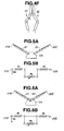
- Figs. 4A to 4F are diagrams for explaining driving states of the first medical device 21 and the second medical device 21.
- Figs. 5A, 5B, 6A, and 6B are diagrams for explaining inter-device electric resistance value between the surface of the first medical device 21 and the surface of the second medical device 21.
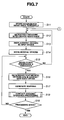
- Figs. 7 and 8 are flowcharts for explaining a flow of the operation of the medical device system 1 according to the present embodiment.
- the first medical device 21 and the second medical device 22 are projected from the forceps holes 12 to start treatment.
- the first medical device 21 and the second medical device 22 are projected from the distal end portion of the endoscope 10 and used.
- the first medical device 21 and the second medical device 22 may be projected when the endoscope 10 is inserted.
- the threshold storing means 36 stores an inter-device resistance threshold Rc inputted by the surgeon using the input means.
- the inter-device resistance threshold Rc is a resistance value as a reference for the determining means 34 to determine, when inter-device resistance R is smaller than the inter-device resistance threshold Rc, that the first medical device 21 and the second medical device 22 are in contact with each other.
- the inter-device resistance threshold Rc a value stored by another storing means in advance, a value inputted from the surgeon using the input means 41, or the like is used.
- the inter-device resistance threshold Rc is desirably 0.1 to 1000 ohms and, particularly desirably 5 to 10 ohms.
- the inter-device resistance threshold Rc is smaller than the range, in some cases, it is determined by the determining means that the first medical device 21 and the second medical device 22 are in non-contact with each other although the medical devices are actually in contact with each other.
- the inter-device resistance threshold Rc exceeds the range, in some cases, it is determined that the first medical device 21 and the second medical device 22 are in contact with each other although the medical devices are actually in non-contact with each other.
- the inter-device resistance threshold Rc is calculated from an inter-device resistance value R1 at the start of operation of the medical device system 1.
- the inter-device resistance value R1 at the start of the operation of the medical device system 1 is a resistance value R1 at the time when the first medical device 21 and the second medical device 22 are in non-contact with each other not only directly but also indirectly via the living tissue VA. It is advisable to set a resistance value of, for example, one tenth of this resistance value R1 as the inter-device resistance threshold Rc.
- inter-device resistance Rr indicates a low value and the determining means 34 malfunctions.
- the inter-device resistance threshold Rc is set lower than usual.
- an inter-device resistance value R2 at the time when the first medical device 21 and the second medical device 22 are indirectly in contact with each other via the living tissue VA, which is actually being treated, may be measured by the resistance measuring means 37 and the inter-device resistance threshold Rc may be calculated from R2.
- the electric current and the voltage may be intermittently applied to measure resistance.
- the measurement of an inter-device resistance value may be performed by any one of driving systems, i.e., constant current driving and constant voltage driving.
- the measurement of an inter-device resistance value may be performed by an alternating current rather than a direct current.
- FIG. 5A shows a state in which the first medical device 21 and the second medical device 22 are electrically in contact with each other via the living tissue VA.
- Fig. 5B shows resistance in the state.
- An inter-device resistance value between the first electrode 21 E and the second electrode 22E is a sum (R1+R2+R4) of resistance R1 of the first medical device 21 itself, resistance R2 of the second medical device 22 itself, and resistance R4 of the living tissue VA.
- the resistance R4 of the living tissue VA is a value that changes according to, for example, a positional relation between the first medical device 21 and the second medical device 22.
- R3 is resistance from the first electrode 22E1 to the ground and can be arbitrarily set.
- R1, R2, and R3 are resistances of a conductive material and are extremely low compared with the resistance R4 of the living tissue VA. In other words, since R4 » R1, R2, and R3, the inter-device resistance value (R1+R2+R4) is substantially (R4).
- the operation control means 33 drives the driving means 42a and, as shown in Figs. 4A to 4B , the first medical device 21 starts movement.
- the inter-device resistance value between the first electrode 21E and the second electrode 22E can be regarded as a sum (R1+R2) of the resistance R1 of the first medical device 21 itself and the resistance R2 of the second medical device 22 itself.
- R4 >> R1 and R2.
- the inter-device resistance value (R1+R2) is a value smaller than the inter-device resistance threshold Rc.
- the control device 30 When the inter-device resistance value is higher than the inter-device resistance threshold Rc (NO), the control device 30 returns to step S12 and continues normal control.
- the determining means 34 determines that the first medical device 21 and the second medical device 22 come into contact with each other and sends a signal to the warning generating means 35.
- the warning generating means 35 generates warning according to the determination by the determining means 34 that the first medical device 21 and the second medical device 22 come into contact with each other.
- the warning is transmitted to the surgeon by a publicly-known warning method.
- the warning generated by the warning generating means 35 is transmitted to the control means 31 as an electric signal.
- the control means 31 controls to perform contact avoiding operation processing explained later.
- the control device 30 When the inter-device resistance value increases to be higher than the inter-device resistance threshold Rc according to contact avoiding operation, i.e., when the contact is released, the control device 30 returns to (I) and continues the normal control until a treatment end instruction is received (YES).
- the control means 31 of the medical device system 1 according to the present embodiment can also perform auxiliary operation when the surgeon learns occurrence of contact according to warning and performs operation for contact release.
- the control means 31 checks whether treatment of any one of contact avoiding operations (a), (b), and (c) selected by the surgeon in advance is performed or the avoiding operation control is not performed when warning is generated by the warning generating means 35, i.e., when a warning signal is received from the warning generating means 35.
- the control means 31 of the medical device system 1 can avoid further contact by performing control for stopping the operation of the driving means 42a and 42b when warning is generated by the warning generating means 35.
- control means 31 cancels all inputs of operations signals by the operation arm of the manual-operation input means 40a and stops moving operation of the first medical device 21 as shown in Fig. 4D .
- the operation storing means 32 has stored therein operation information of the driving means, i.e., operation information of the medical devices. Therefore, the control means 31 can control, on the basis of the operation information stored by the operation storing means 32, the driving means 31 to prohibit further movement in a moving direction in which the first medical device 21 moves before the control means 31 receives warning, i.e., before contact occurs. Prohibiting the movement means that, even if a moving instruction from the input means or the like by the surgeon is received, the instruction is cancelled and is not executed.
- the surgeon can safely separate the first medical device 21 from the second medical device 22 by moving the first medical device 21 in a movable direction different from the moving direction of the first medical device before the contact as shown in Fig. 4E .
- control means 31 can avoid further contact between the medical devices by prohibiting movement in the (+X, -Y, +Z) direction and allowing the first medical device 21 to move only in an opposite vector direction.
- the operation storing means 32 has stored therein the operation information of the driving means, i.e., the operation information of the medical devices. Therefore, as shown in Fig. 4F , the control means 31 can return a state of the driving means 42a, i.e., a state of the first medical device 21 to a state before the control means 31 receives warning, i.e., a state before the contact.
- the surgeon selects a degree of returning the state of the first medical device 21 to the state before the contact occurrence.
- a unit for returning the state of the first medical device 21 to the state before the contact occurrence for example, an operation step unit of the driving means, a time unit, or the like can be selected. However, for example, it is advisable to return the state of the first medical device 21 to a state two seconds before the contact occurrence.
- the operation storing means 32 has stored therein the operation of the first medical device. Therefore, the control means 31 can control the driving means to return the state of the driving means 42a, i.e., the state of the first medical device 21 to the state before the warning occurrence by the warning generating means 35, i.e., the state before the contact.
- the operation arm of the manual-operation input means 40a can be returned to a position before the contact in the same manner as the return operation of the first medical device 21.
- the control means 31 performs control for returning a state of physical displacement of the manual-operation input means having the driving mechanism to a state before the contact.
- Step S23 and step S24 are simultaneously performed in parallel.
- the contact avoiding operation and the returning operation are performed according to selection by the surgeon.
- the surgeon may select the operations in advance, may select the operation according to a state after contact occurrence, or may select another operation during or after the contact avoiding operation.
- the first medical device 21 moves.
- Figs. 9 to 9G are diagrams for explaining combinations of the first medical device 21 and the second medical device 22 as modifications of the first embodiment.
- one or both of the first medical device 21 and the second medical device 22 are active medical devises having driving means, for example, active treatment instruments or active endoscopes.
- Fig. 9A is a case in which the first medical device 21 is an active treatment instrument 21a of the endoscope 10 and the second medical device 22 is an active treatment instrument 22a of the endoscope 10.
- Fig. 9B is a case in which the first medical device 21 is an active treatment instrument 21 b of an endoscope 10a and the second medical device 22 is an active treatment instrument active treatment instrument 22b of another endoscope 10b.
- Fig. 9C is a case in which the first medical device 21 is the endoscope 10a (21 c) itself and the second medical device 22 is an active treatment instrument active treatment instrument 22c of the endoscope 10a.
- Fig. 9D is a case in which the first medical device 21 is an active treatment instrument active treatment instrument 21d of the endoscope 10a and the second medical device 22 is an endoscope 10c (22d) itself.
- Fig. 9E is a case in which the first medical device 21 is an active endoscope 10d (21e) itself and the second medical device 22 is the active endoscope 10d (22e) itself.
- Fig. 9F is a case in which the first medical device 21 is the active endoscope 10d (21 f) itself and the second medical device 22 is another rigid endoscope 10e (22f) itself.
- Fig. 9G is a case in which the first medical device 21 is an active treatment instrument 21 g of a rigid endoscope 10f and the second medical device 22 is the active endoscope 10c (22g) itself.
- Fig. 10 shows a case in which the first medical device 21 is the active endoscope 21e and the second medical device 22 is another active endoscope 22e.
- the active endoscope 21e and the active endoscope 22e are respectively configured such that surfaces 53 and 54 thereof are conductive. Therefore, when the active endoscope 21e and the active endoscope 22e come into contact with each other, the control device 30 can detect the contact and perform the contact avoiding operation.
- Fig. 11 shows a case in which the first medical device 21 is the endoscope 21 c and the second medical device 22 is the active treatment instrument 22c of the endoscope 21 c.
- the first medical device 21 is the endoscope 21 c and the second medical device 22 is projected from a distal end portion of the endoscope 21c and used.
- a surface 55 of the endoscope 21c and a surface of the active treatment instrument 22c are configured to be conductive. Therefore, when the endoscope 21c and the active treatment instrument 22c come into contact with each other, the control device 30 can detect the contact and perform the contact avoiding operation.
- first medical device 21 and the second medical device 22 with other single or plural medical devices, contact among which does not need to be detected, or detect contact among three or more medical devices.
- contact among the three or more medical devices is detected, surfaces of all the medical devices as contact detection targets are made conductive and inter-device resistance among the medical devices is measured.
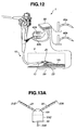
- FIG. 12 is a configuration diagram of the medical device system 1 according to the present embodiment.
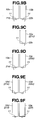
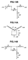
- Fig. 13A , 13B, 14A, and 14B are diagrams for explaining an inter-device electric resistance value and an electrode-to-human body resistance value of the medical device system 1 according to the present embodiment.
- a basic configuration of the medical device system 1 according to the present embodiment is similar to that of the medical device system according to the first embodiment shown in Figs. 1 and 2 .
- the medical device system 1 according to the present embodiment includes a human body electrode plate 59 and a human body electrode 59E connected to the human body electrode plate 59.
- the human body electrode plate 59 is an electrode plate that is brought into contact with the human body.
- the resistance measuring means 37 measures, together with an inter-device resistance value, an electrode-to-human body resistance value as electric resistance between the first electrode or the second electrode and the human body electrode.
- Fig. 13A shows a state in which the first medical device 21 and the second medical device 22 are electrically in contact with each other via the living tissue AV.
- Fig. 13B shows resistance in the state.
- the inter-device resistance value between the first electrode 21E and the second electrode 22E is a sum (R1+R2+R4) of the resistance R1 of the first medical device 21 itself, the resistance R2 of the second medical device 22 itself, and the resistance R4 of the living tissue VA.
- the resistance R4 of the living tissue AV is a value that changes according to, for example, a positional relation between the first medical device 21 and the second medical device 22.
- R3 and R6 are up resistance from the ground.
- An electrode-to-human body resistance value as electric resistance between the second electrode and the human body electrode is a sum (R2+R5) of R5 as electric resistance of the human body and the resistance R2 of the second medical device 22 itself. Therefore, an electric resistance value ratio as a ratio of the inter-device electric resistance value and the electrode-to-human body resistance value is (R1+R2+R4)/(R2+R5). Since R5 as the electric resistance of the human body is higher than the resistance R4 of the living tissue VA, R5 >> R4 >> R1, R2, R3, and R6.
- the inter-device resistance value between the first electrode 21E and the second electrode 22E is substantially a sum (R1+R2) of the resistance R1 of the medical device 21 itself and the resistance R2 of the second medical device 22 itself.
- the electrode-to-human body resistance value does not change from (R2+R5). Therefore, the electric resistance value ratio as the ratio of the inter-device electric resistance value and the electrode-to-human body resistance value is (R1+R2)/(R2+R5). Therefore, it is evident that the electric resistance value ratio substantially decreases because of the contact. In other words, since the electric resistance value ratio substantially decreases from 1/2 to 1/100, it is possible to determine that the first medical device 21 comes into contact with the second medical device 22.
- the medical device system 1 it is possible to determine presence or absence of contact on the basis of a ratio of electric resistances rather than level of electric resistances. Therefore, highly accurate contact detection is possible.
- the electric resistance between the second electrode and the human body electrode is set as the electrode-to-human body resistance value.
- contact between the first medical device 21 and the second medical device 22 is determined according to electric resistance.
- Electric current, voltage, and resistance may be used for contact detection in combination.
- Figs. 15, 16A, and 16B are diagrams for explaining the modification of the medical device 21 or 22 according to the present embodiment.
- a conductive area 51 A on the surface of the first medical device 21 shown in Fig. 15 is divided into three portions 51 a, 51 b, and 51 c. Areas among the portions are nonconductive. Electrodes electrically connected to respective conductive area surfaces are provided. Therefore, when the first medical device 21 and the not-shown second medical device 22 come into contact with each other, it is seen which of the three portions 51 a, 51 b, and 51c of the first medical device 21 is in contact with the second medical device 22. Therefore, the surgeon can more safely take contact avoiding measures.
- the conductive area 51 A on the surface of the first medical device 21 shown in Figs. 16A and 16B is divided into four portions 51d, 51 e, 51 f, and 51 g in a circumferential direction as shown in a medical device longitudinal vertical direction sectional view of Fig. 16B . Areas among the portions are nonconductive. Therefore, when the first medical device 21 and the not-shown second medical device 22 come into contact with each other, it is seen in which direction the second medical device 22 is in contact with the first medical device. Therefore, the surgeon can more safely take contact avoiding measures.
- an electrode may be formed for each of links.
- the medical device 21 or 22 having a large number of divided conductive surface areas can obtain more detailed information concerning a contact place.
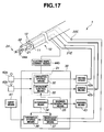
- Fig. 17 is a block diagram of the medical device system 1 having the medical device 21 including an electric knife 44a.
- the medical device system 1 according to the present embodiment includes the electric knife 44a in the first medical device 21 and further includes electric knife control means 44b, a not-shown high-frequency power supply, and the like for the electric knife 44a.
- An electric knife device is used for performing treatment such as dissection, coagulation, and hemostasis for a living tissue.
- the electric knife device includes the electric knife control means 44b, the not-shown high-frequency power supply connected to the electric knife control means 44b, and the electric knife 44a.
- the electric knife device supplies high-frequency power from the high-frequency power supply to the electric knife 44a, which is brought into contact with the living tissue, and cauterizes the living tissue with energy of the high-frequency power.
- the control means 31 performs control for controlling the electric knife control means 44b to stop or reduce output of the electric knife 44a.
- the control means 31 performs control of the electric knife control means 44b.
- the control means 31 sends a signal to the electric knife control means 44b and stops or reduces output of the high-frequency power supply. The surgeon sets in the control means 31 in advance what kind of control of the electric knife control means should be performed.
- the output of the electric knife 44a stops or falls. Therefore, it is possible to more safely perform treatment.
- the present invention is not limited to the embodiments above. Various modifications, alterations, and the like are possible in a range in which the gist of the present invention is not changed.
Landscapes
- Health & Medical Sciences (AREA)
- Life Sciences & Earth Sciences (AREA)
- Surgery (AREA)
- Engineering & Computer Science (AREA)
- General Health & Medical Sciences (AREA)
- Veterinary Medicine (AREA)
- Public Health (AREA)
- Animal Behavior & Ethology (AREA)
- Molecular Biology (AREA)
- Medical Informatics (AREA)
- Biomedical Technology (AREA)
- Heart & Thoracic Surgery (AREA)
- Nuclear Medicine, Radiotherapy & Molecular Imaging (AREA)
- Biophysics (AREA)
- Physics & Mathematics (AREA)
- Pathology (AREA)
- Radiology & Medical Imaging (AREA)
- Optics & Photonics (AREA)
- Robotics (AREA)
- Surgical Instruments (AREA)
- Endoscopes (AREA)
- Investigating Or Analyzing Materials By The Use Of Electric Means (AREA)
Abstract
Description
- The present invention relates to a medical device system, and, more particularly to a medical device system having plural medical devices that are likely to come into contact with one another in a body cavity.
- In recent years, so-called endoscopic surgery that can minimize invasion in a patient compared with surgical operation involving laparotomy, thoracotomy, and the like has been performed. In particular, laparoscopic surgical operation is widely performed. This laparoscopic surgical operation is an operation performed by using a medical device inserted through a small dissected opening of the skin of a patient. In the laparoscopic surgical operation, after CO2 is injected into an abdominal cavity to form a space necessary for the operation as pneumoperitoneum, a medical device having an elongated insertion portion is inserted through a trocar (a mantle tube) pierced into an epigastria region while the region being observed by an endoscope and the operation is performed.
- In endoscopic surgical operation, since the endoscope and the medical device have to be operated in the narrow pneumoperitoneum or the like, contact between endoscope and medical devices, or when plural medical devices are used, contact among the medical devices tends to occur. When contact between the endoscope and the medical devices or contact among the medical devices occurs, unnecessary force is applied to the medical devices. It is likely that breakage of the medical devices or an operation failure of the medical devices, specifically, wire cut, breakage or deformation of a movable portion, or the like occur. It is also likely that action of the medical devices unintended by a surgeon occurs because of the influence of the contact among the medical devices.
- In order to avoid such contact among the medical devices, Japanese Patent Application Laid-Open Publication No.
2004-81277 - Japanese Patent Application Laid-Open Publication No.
2004-89591 - Specifically, the sensor for detecting the contact between the surgical device and the endoscope disclosed in Japanese Patent Application Laid-Open Publication
2004-81277 - In the medical device having the electric manipulator disclosed in Japanese Patent Application Laid-Open Publication No.
2004-89591 - On the other hand, the present invention can provide a medical device system that can detect, at an early stage, contact among medical devices used in a body cavity and prevent breakage and the like of the medical devices.
- In order to attain the object, a medical device system according to the present invention includes: first and second medical devices, each of which is used in a body cavity and surfaces of which have conductivity; a first electrode electrically connected to the surface of the first medical device; a second electrode electrically connected to the surface of the second medical device; resistance measuring means for measuring an inter-device electric resistance value as electric resistance between the first electrode and the second electrode; threshold storing means for storing an inter-device resistance threshold as a lower limit value of the inter-device resistance value; determining means for determining, when the inter-device resistance value is lower than the inter-device resistance threshold, that the first medical device and the second medical device have come into contact with each other; and warning generating means for generating a warning when the determining means determines that the first medical device and the second medical device have come into contact with each other.
-
-
Fig. 1 is a configuration diagram of a medical device system according to a first embodiment; -
Fig. 2 is a block diagram of amedical device system 1 according to the first embodiment; -
Fig. 3A is a perspective view of a first medical device; -
Fig. 3B is a sectional view in a longitudinal vertical direction of the first medical device; -
Fig. 4A is a diagram for explaining driving states of the first medical device and a second medical device; -
Fig. 4B is a diagram for explaining driving states of the first medical device and the second medical device; -
Fig. 4C is a diagram for explaining driving states of the first medical device and the second medical device; -
Fig. 4D is a diagram for explaining driving states of the first medical device and the second medical device; -
Fig. 4E is a diagram for explaining driving states of the first medical device and the second medical device; -
Fig. 4F is a diagram for explaining driving states of the first medical device and the second medical device; -
Fig. 5A is a diagram for explaining an inter-device electric resistance value between a surface of the first medical device and a surface of the second medical device; -
Fig. 5B is a diagram for explaining the inter-device electric resistance value between the surface of the first medical device and the surface of the second medical device; -
Fig. 6A is a diagram for explaining an inter-device electric resistance value between the surface of the first medical device and the surface of the second medical device; -
Fig. 6B is a diagram for explaining the inter-device electric resistance value between the surface of the first medical device and the surface of the second medical device; -
Fig. 7 is a flowchart for explaining a flow of operation of the medical device system; -
Fig. 8 is a flowchart for explaining a flow of operation of the medical device system; -
Fig. 9A is a diagram for explaining a combination of a first medical device and a second medical device as a modification of the first embodiment; -
Fig. 9B is a diagram for explaining a combination of the first medical device and the second medical device as a modification of the first embodiment; -
Fig. 9C is a diagram for explaining a combination of the first medical device and the second medical device as a modification of the first embodiment; -
Fig. 9D is a diagram for explaining a combination of the first medical device and the second medical device as a modification of the first embodiment; -
Fig. 9E is a diagram for explaining a combination of the first medical device and the second medical device as a modification of the first embodiment; -
Fig. 9F is a diagram for explaining a combination of the first medical device and the second medical device as a modification of the first embodiment; -
Fig. 9G is a diagram for explaining a combination of the first medical device and the second medical device as a modification of the first embodiment; -
Fig. 10 is a diagram for explaining a combination of the first medical device and the second medical device as a modification of the first embodiment; -
Fig. 11 is a diagram for explaining a combination of the first medical device and the second medical device as a modification of the first embodiment; -
Fig. 12 is a configuration diagram of a medical device system according to a second embodiment; -
Fig. 13A is a diagram for explaining an inter-device electric resistance value and an electrode-to-human body resistance value of the medical device system according to the second embodiment; -
Fig. 13B is a diagram for explaining the inter-device electric resistance value and the electrode-to-human body resistance value of the medical device system according to the second embodiment; -
Fig. 14A is a diagram for explaining an inter-device electric resistance value and an electrode-to-human body resistance value of the medical device system according to the second embodiment; -
Fig. 14B is a diagram for explaining the inter-device electric resistance value and the electrode-to-human body resistance value of the medical device system according to the second embodiment; -
Fig. 15 is a diagram for explaining a modification of the medical device; -
Fig. 16A is a diagram for explaining a modification of the medical device; -
Fig. 16B is a diagram for explaining the modification of the medical device; and -
Fig. 17 is a block diagram of a medical device system having medical devices including electric knives. - Embodiments of the present invention are explained below with reference to the drawings.
-
Fig. 1 is a configuration diagram for explaining amedical device system 1 according to a first embodiment of the present invention. Themedical device system 1 includes anendoscope 10 including anobservation lens 11 at a distal end thereof, a firstmedical device 21, a secondmedical device 22, driving means 42a and 42b, acontrol device 30, and input means 40a and 40b. - The first
medical device 21 and the secondmedical device 22 project from a distal end portion of theendoscope 10 inserted in vivo and are used for performing an operation on a living tissue VA in body cavity V. The firstmedical device 21 and the secondmedical device 22 are active medical devices that are electrically driven with input information from the respective manual-operation input means 40a and 40b transmitted to the respective driving means 42a and 42b via thecontrol device 30. The manual-operation input means 40a and 40b are input means for converting three-dimensional motion of operation arms of an input device by a surgeon, i.e., physical displacement of the input device into an electric signal. - The respective manual-operation input means are devices adjusted to the respective medical devices. For example, when the medical devices have two joints, the manual-operation input means also have two joints. Therefore, the surgeon can apply desired operation to the medical devices by operating the manual-operation input means. When a motion amount of the medical devices is set small with respect to an actual physical displacement amount of the operation arms of the manual-operation input means, the surgeon can easily realize extremely fine motion of the medical devices.
- Next,
Fig. 2 is a block diagram of themedical device system 1 according to the present embodiment. As shown inFig. 2 , the firstmedical device 21 and the secondmedical device 22 project fromforceps holes 12 at the distal end portion of theendoscope 10. Surfaces of the medical devices have conductivity. This does not mean that the medical devices themselves do not always need to be made of a conductive material, for example, SUS and the surfaces of the medical devices at least have to be coated with a material having conductivity. Themedical device system 1 includes afirst electrode 21E electrically connected to the surface of the firstmedical device 21 by an electric wire and asecond electrode 22E electrically connected to the surface of the secondmedical device 22 by an electric wire. Electric resistance between thefirst electrode 21E and thesecond electrode 22E, i.e., an inter-device electric resistance value is measured by resistance measuring means 37. - The first
medical device 21 and the secondmedical device 22 respectively have aknife arm 23 andhand arms 24. The firstmedical device 21 and the secondmedical device 22 are active medical devices driven by the driving means 42a and 42b according to instructions from the respective input means 40a and 40b via the control means 31. Thecontrol device 30 includes threshold storing means 36 for storing a threshold of inter-device resistance inputted from the input means 41, determining means 34 for determining whether the inter-device resistance is smaller than the threshold of the inter-device resistance stored in the threshold storing means 36, and warning generating means 35 for generating a warning on the basis of the determination of the determiningmeans 34. The warning generated by the warning generating means 35 is transmitted to the surgeon by publicly-known warning such as sound, light, or vibration of warning means 43. The warning generated by the warning generating means 35 is transmitted to the control means 31 as an electric signal. When the control means 31 receives the warning signal, the control means 31 controls to perform contact avoiding operation explained later. - The manual-operation input means 40a and 40b are different depending on a type of an electric driving mechanism for medical devices. As manual-operation input means for a biaxially operating medical device, a normal joystick can be used. In a medical device that can perform more complicated operation, the manual operation input means called operation arms for converting three-dimensional motion of hands of a surgeon to front and back, up and down, and left and right into an electric signal is used. In both the manual-operation input means, the motion of the hands of the surgeon is detected by sensors or the like disposed in the manual-operation input means. Information concerning physical displacement of the manual-operation input means is converted into an electric signal.
- The manual-operation input means 40a and 40b themselves have not-shown driving mechanisms. By using the manual-operation input means 40a and 40b having the driving mechanisms, contrary to converting the motion of the hands of the surgeon into an electric signal, it is possible to generate force in an opposite direction against operation of the operation arms or the like by the motion of the hands of the surgeon to restrict the motion of the hands of the surgeon or change displacement of the operation arms or the like according to motion of the active medical devices unrelated to the surgeon as explained later.
- The
control device 30 may have operation storing means 32. The operation storing means 32 stores, together with elapsed time, operation of the firstmedical device 21 and the secondmedical device 22 by the operation control means 33 and displacement of the manual-operation input means 40a and 40b. - Next, an example of the first
medical device 21 according to the present embodiment is explained with reference toFigs. 3A and3B .Fig. 3A is a perspective view of the firstmedical device 21 andFig. 3B is a sectional view in a longitudinal vertical direction of the firstmedical device 21. As shown inFig. 3A , the firstmedical device 21 has two bendable joints 21J1 and 21J2. Not-shown wires are connected to the two joints 21J1 and 21J2. The respective wires are connected to the driving means 42a and 42b. The two joints 21J1 and 21J2 are bendable according to advance and retract of the wires. The firstmedical device 21 is made of SUS. Even if the firstmedical device 21 is joined via the two joints 21J1 and 21 J2, since links of bending portions are formed of a highly conductive raw material, for example, SUS, the firstmedical device 21 electrically has integrated structure. Anelectric wire 21e is connected from a connecting section provided in an inside thereof to theelectrode 21 E. - A
knife arm 23 is inserted through the firstmedical device 21. A distal end of the firstmedical device 21 is made of an insulating material for electric insulation from theknife arm 23. However, asurface 21 A of the firstmedical device 21 other than the distal end has conductivity. - The second
medical device 22 is also a multi-joint manipulator having a configuration similar to that of the firstmedical device 21. Therefore, themedical device system 1 according to the present embodiment can detect contact between the first electrode of the first medical device and the second medical device by measuring electric resistance between the first electrode of the first medical device and the second electrode of the second medical device. - Next, operation of the
medical device system 1 according to the present embodiment is explained with reference toFigs. 4A to 8 .Figs. 4A to 4F are diagrams for explaining driving states of the firstmedical device 21 and the secondmedical device 21.Figs. 5A, 5B, 6A, and 6B are diagrams for explaining inter-device electric resistance value between the surface of the firstmedical device 21 and the surface of the secondmedical device 21.Figs. 7 and8 are flowcharts for explaining a flow of the operation of themedical device system 1 according to the present embodiment. - The flow of the operation of the
medical device system 1 according to the present embodiment is explained below according to the flowchart shown inFig. 7 . - When the
endoscope 10 is inserted into a body cavity V and reaches a target region, the firstmedical device 21 and the secondmedical device 22 are projected from the forceps holes 12 to start treatment. In other words, the firstmedical device 21 and the secondmedical device 22 are projected from the distal end portion of theendoscope 10 and used. The firstmedical device 21 and the secondmedical device 22 may be projected when theendoscope 10 is inserted. - The threshold storing means 36 stores an inter-device resistance threshold Rc inputted by the surgeon using the input means. The inter-device resistance threshold Rc is a resistance value as a reference for the determining means 34 to determine, when inter-device resistance R is smaller than the inter-device resistance threshold Rc, that the first
medical device 21 and the secondmedical device 22 are in contact with each other. - As the inter-device resistance threshold Rc, a value stored by another storing means in advance, a value inputted from the surgeon using the input means 41, or the like is used. For example, the inter-device resistance threshold Rc is desirably 0.1 to 1000 ohms and, particularly desirably 5 to 10 ohms. When the inter-device resistance threshold Rc is smaller than the range, in some cases, it is determined by the determining means that the first
medical device 21 and the secondmedical device 22 are in non-contact with each other although the medical devices are actually in contact with each other. When the inter-device resistance threshold Rc exceeds the range, in some cases, it is determined that the firstmedical device 21 and the secondmedical device 22 are in contact with each other although the medical devices are actually in non-contact with each other. - It is also possible to calculate the inter-device resistance threshold Rc from an inter-device resistance value R1 at the start of operation of the
medical device system 1. Specifically, the inter-device resistance value R1 at the start of the operation of themedical device system 1 is a resistance value R1 at the time when the firstmedical device 21 and the secondmedical device 22 are in non-contact with each other not only directly but also indirectly via the living tissue VA. It is advisable to set a resistance value of, for example, one tenth of this resistance value R1 as the inter-device resistance threshold Rc. - Depending on a living tissue, since a resistance value thereof is relatively small, when the first
medical device 21 and the secondmedical device 22 indirectly come into contact with each other via the living tissue VA, in some cases, inter-device resistance Rr indicates a low value and the determiningmeans 34 malfunctions. In this case, the inter-device resistance threshold Rc is set lower than usual. Alternatively, an inter-device resistance value R2 at the time when the firstmedical device 21 and the secondmedical device 22 are indirectly in contact with each other via the living tissue VA, which is actually being treated, may be measured by the resistance measuring means 37 and the inter-device resistance threshold Rc may be calculated from R2. - Measurement of inter-device resistance value by the
resistance detecting means 37 is started. - It is advisable to set electric current and voltage used for measurement of an inter-device resistance value by the
resistance detecting means 37 to feeble electric current and voltage that do not damage the living tissue VA, for example, 0.1 to 10 V and 0.1 to 500 mA. When the electric current and the voltage are smaller than the ranges, in some cases, accurate resistance measurement is difficult because of noise or the like. When the electric current and the voltage are equal to or larger than the ranges, in some cases, the living tissue VA is damaged. - For the measurement of an inter-device resistance value by the
resistance detecting means 37, it is unnecessary to continuously apply the electric current and the voltage. The electric current and the voltage may be intermittently applied to measure resistance. The measurement of an inter-device resistance value may be performed by any one of driving systems, i.e., constant current driving and constant voltage driving. The measurement of an inter-device resistance value may be performed by an alternating current rather than a direct current. - An inter-device electric resistance value at a stage when the measurement of an inter-device resistance value is started is explained with reference to
Figs. 5A and 5B. Fig. 5A shows a state in which the firstmedical device 21 and the secondmedical device 22 are electrically in contact with each other via the living tissue VA.Fig. 5B shows resistance in the state. An inter-device resistance value between thefirst electrode 21 E and thesecond electrode 22E is a sum (R1+R2+R4) of resistance R1 of the firstmedical device 21 itself, resistance R2 of the secondmedical device 22 itself, and resistance R4 of the living tissue VA. The resistance R4 of the living tissue VA is a value that changes according to, for example, a positional relation between the firstmedical device 21 and the secondmedical device 22. R3 is resistance from the first electrode 22E1 to the ground and can be arbitrarily set. - R1, R2, and R3 are resistances of a conductive material and are extremely low compared with the resistance R4 of the living tissue VA. In other words, since R4 » R1, R2, and R3, the inter-device resistance value (R1+R2+R4) is substantially (R4).
- It is evident that an inter-device resistance value in a state in which the first
medical device 21 and the secondmedical device 22 are not in contact with the living tissue VA is extremely large resistance due to a leak current or the like. - Physical displacement occurs in the operation arm of the manual-operation input means 40a because of the operation by the surgeon.
- According to the physical displacement of the manual-operation input means 40a converted into an electric signal, the operation control means 33 drives the driving means 42a and, as shown in
Figs. 4A to 4B , the firstmedical device 21 starts movement. - Next, an inter-device resistance value in the case in which the first
medical device 21 and the secondmedical device 22 come into contact with each other as shown inFig. 4C is explained with reference toFigs. 6A and 6B . - When the first
medical device 21 comes into contact with the secondmedical device 22 as shown inFig. 6A (YES), since the surfaces of both the medical devices have conductivity, resistance between the surfaces of both the medical devices is extremely low. Therefore, the inter-device resistance value between thefirst electrode 21E and thesecond electrode 22E can be regarded as a sum (R1+R2) of the resistance R1 of the firstmedical device 21 itself and the resistance R2 of the secondmedical device 22 itself. As explained in step S12, R4 >> R1 and R2. The inter-device resistance value (R1+R2) is a value smaller than the inter-device resistance threshold Rc. - When the inter-device resistance value is higher than the inter-device resistance threshold Rc (NO), the
control device 30 returns to step S12 and continues normal control. - When the inter-device resistance value decreases to be lower than the inter-device resistance threshold Rc, the determining
means 34 determines that the firstmedical device 21 and the secondmedical device 22 come into contact with each other and sends a signal to the warning generating means 35. - The warning generating means 35 generates warning according to the determination by the determining means 34 that the first
medical device 21 and the secondmedical device 22 come into contact with each other. The warning is transmitted to the surgeon by a publicly-known warning method. - The warning generated by the warning generating means 35 is transmitted to the control means 31 as an electric signal. When the control means 31 receives the warning signal, the control means 31 controls to perform contact avoiding operation processing explained later.
- When the inter-device resistance value increases to be higher than the inter-device resistance threshold Rc according to contact avoiding operation, i.e., when the contact is released, the
control device 30 returns to (I) and continues the normal control until a treatment end instruction is received (YES). - Next, contact avoiding operation is explained with reference to
Fig. 8 . The control means 31 of themedical device system 1 according to the present embodiment can also perform auxiliary operation when the surgeon learns occurrence of contact according to warning and performs operation for contact release. - The control means 31 checks whether treatment of any one of contact avoiding operations (a), (b), and (c) selected by the surgeon in advance is performed or the avoiding operation control is not performed when warning is generated by the warning generating means 35, i.e., when a warning signal is received from the warning generating means 35.
- The control means 31 of the
medical device system 1 according to the present embodiment can avoid further contact by performing control for stopping the operation of the driving means 42a and 42b when warning is generated by the warning generating means 35. - Specifically, the control means 31 cancels all inputs of operations signals by the operation arm of the manual-operation input means 40a and stops moving operation of the first
medical device 21 as shown inFig. 4D . - Since the operation of the first medical device is stopped, damage to the medical device and the like due to further contact are prevented. To continue the treatment again, it is necessary to perform moving operation for safely separating the first
medical device 21 from the secondmedical device 22. - In the
medical device system 1 according to the present embodiment, the operation storing means 32 has stored therein operation information of the driving means, i.e., operation information of the medical devices. Therefore, the control means 31 can control, on the basis of the operation information stored by the operation storing means 32, the driving means 31 to prohibit further movement in a moving direction in which the firstmedical device 21 moves before the control means 31 receives warning, i.e., before contact occurs. Prohibiting the movement means that, even if a moving instruction from the input means or the like by the surgeon is received, the instruction is cancelled and is not executed. - Therefore, the surgeon can safely separate the first
medical device 21 from the secondmedical device 22 by moving the firstmedical device 21 in a movable direction different from the moving direction of the first medical device before the contact as shown inFig. 4E . - Specifically, for example, when a moving direction of the
medical device 21 immediately before the contact is a certain direction vector (+X, -Y, +Z) in a three-dimensional space, the control means 31 can avoid further contact between the medical devices by prohibiting movement in the (+X, -Y, +Z) direction and allowing the firstmedical device 21 to move only in an opposite vector direction. - In the
medical device system 1 according to the present embodiment, the operation storing means 32 has stored therein the operation information of the driving means, i.e., the operation information of the medical devices. Therefore, as shown inFig. 4F , the control means 31 can return a state of the driving means 42a, i.e., a state of the firstmedical device 21 to a state before the control means 31 receives warning, i.e., a state before the contact. - The surgeon selects a degree of returning the state of the first
medical device 21 to the state before the contact occurrence. As a unit for returning the state of the firstmedical device 21 to the state before the contact occurrence, for example, an operation step unit of the driving means, a time unit, or the like can be selected. However, for example, it is advisable to return the state of the firstmedical device 21 to a state two seconds before the contact occurrence. - In the
medical device system 1 according to the present embodiment, the operation storing means 32 has stored therein the operation of the first medical device. Therefore, the control means 31 can control the driving means to return the state of the driving means 42a, i.e., the state of the firstmedical device 21 to the state before the warning occurrence by the warning generating means 35, i.e., the state before the contact. - Further, the operation arm of the manual-operation input means 40a can be returned to a position before the contact in the same manner as the return operation of the first
medical device 21. Specifically, the control means 31 performs control for returning a state of physical displacement of the manual-operation input means having the driving mechanism to a state before the contact. - The surgeon can resume the operation after checking a returned state of the first
medical device 21 according to a state change of the operation arm of the manual-operation input means 40a. Step S23 and step S24 are simultaneously performed in parallel. - The contact avoiding operation and the returning operation are performed according to selection by the surgeon. The surgeon may select the operations in advance, may select the operation according to a state after contact occurrence, or may select another operation during or after the contact avoiding operation.
- In the above explanation, the first
medical device 21 moves. However, the same holds true in the case of contact occurrence due to movement of the secondmedical device 22 and when contact occurs while both the firstmedical device 21 and the secondmedical device 22 simultaneously move. - Combinations of the medical devices as modifications of the first embodiment are explained with reference to
Figs. 9A to 9G .Figs. 9 to 9G are diagrams for explaining combinations of the firstmedical device 21 and the secondmedical device 22 as modifications of the first embodiment. In the modifications of the first embodiment, one or both of the firstmedical device 21 and the secondmedical device 22 are active medical devises having driving means, for example, active treatment instruments or active endoscopes. -
Fig. 9A is a case in which the firstmedical device 21 is anactive treatment instrument 21a of theendoscope 10 and the secondmedical device 22 is anactive treatment instrument 22a of theendoscope 10.Fig. 9B is a case in which the firstmedical device 21 is anactive treatment instrument 21 b of anendoscope 10a and the secondmedical device 22 is an active treatment instrumentactive treatment instrument 22b of anotherendoscope 10b.Fig. 9C is a case in which the firstmedical device 21 is theendoscope 10a (21 c) itself and the secondmedical device 22 is an active treatment instrumentactive treatment instrument 22c of theendoscope 10a.Fig. 9D is a case in which the firstmedical device 21 is an active treatment instrumentactive treatment instrument 21d of theendoscope 10a and the secondmedical device 22 is anendoscope 10c (22d) itself. -
Fig. 9E is a case in which the firstmedical device 21 is anactive endoscope 10d (21e) itself and the secondmedical device 22 is theactive endoscope 10d (22e) itself.Fig. 9F is a case in which the firstmedical device 21 is theactive endoscope 10d (21 f) itself and the secondmedical device 22 is anotherrigid endoscope 10e (22f) itself.Fig. 9G is a case in which the firstmedical device 21 is anactive treatment instrument 21 g of arigid endoscope 10f and the secondmedical device 22 is theactive endoscope 10c (22g) itself. -
Fig. 10 shows a case in which the firstmedical device 21 is theactive endoscope 21e and the secondmedical device 22 is anotheractive endoscope 22e. Theactive endoscope 21e and theactive endoscope 22e are respectively configured such that surfaces 53 and 54 thereof are conductive. Therefore, when theactive endoscope 21e and theactive endoscope 22e come into contact with each other, thecontrol device 30 can detect the contact and perform the contact avoiding operation. -
Fig. 11 shows a case in which the firstmedical device 21 is theendoscope 21 c and the secondmedical device 22 is theactive treatment instrument 22c of theendoscope 21 c. Specifically, the firstmedical device 21 is theendoscope 21 c and the secondmedical device 22 is projected from a distal end portion of theendoscope 21c and used. Asurface 55 of theendoscope 21c and a surface of theactive treatment instrument 22c are configured to be conductive. Therefore, when theendoscope 21c and theactive treatment instrument 22c come into contact with each other, thecontrol device 30 can detect the contact and perform the contact avoiding operation. - As explained above, various modifications of the medical devices according to the present embodiment are possible. It is also possible to combine the first
medical device 21 and the secondmedical device 22 with other single or plural medical devices, contact among which does not need to be detected, or detect contact among three or more medical devices. When the contact among the three or more medical devices is detected, surfaces of all the medical devices as contact detection targets are made conductive and inter-device resistance among the medical devices is measured. - A contact detecting method by the
medical device system 1 according to a second embodiment of the present invention is explained with reference toFigs. 12 to 14B .Fig. 12 is a configuration diagram of themedical device system 1 according to the present embodiment.Fig. 13A ,13B, 14A, and 14B are diagrams for explaining an inter-device electric resistance value and an electrode-to-human body resistance value of themedical device system 1 according to the present embodiment. - As shown in
Fig. 12 , a basic configuration of themedical device system 1 according to the present embodiment is similar to that of the medical device system according to the first embodiment shown inFigs. 1 and2 . However, themedical device system 1 according to the present embodiment includes a humanbody electrode plate 59 and ahuman body electrode 59E connected to the humanbody electrode plate 59. In order to come into contact with a living tissue as a part of a not-shown human body and measure electric resistance of an organism as a conductor, the humanbody electrode plate 59 is an electrode plate that is brought into contact with the human body. The resistance measuring means 37 measures, together with an inter-device resistance value, an electrode-to-human body resistance value as electric resistance between the first electrode or the second electrode and the human body electrode. - A resistance value at a stage when measurement of the inter-device resistance value and the electrode-to-human body resistance value is started is explained with reference to
Figs. 13A and13B .Fig. 13A shows a state in which the firstmedical device 21 and the secondmedical device 22 are electrically in contact with each other via the living tissue AV.Fig. 13B shows resistance in the state. - The inter-device resistance value between the
first electrode 21E and thesecond electrode 22E is a sum (R1+R2+R4) of the resistance R1 of the firstmedical device 21 itself, the resistance R2 of the secondmedical device 22 itself, and the resistance R4 of the living tissue VA. The resistance R4 of the living tissue AV is a value that changes according to, for example, a positional relation between the firstmedical device 21 and the secondmedical device 22. R3 and R6 are up resistance from the ground. - An electrode-to-human body resistance value as electric resistance between the second electrode and the human body electrode is a sum (R2+R5) of R5 as electric resistance of the human body and the resistance R2 of the second
medical device 22 itself. Therefore, an electric resistance value ratio as a ratio of the inter-device electric resistance value and the electrode-to-human body resistance value is (R1+R2+R4)/(R2+R5). Since R5 as the electric resistance of the human body is higher than the resistance R4 of the living tissue VA, R5 >> R4 >> R1, R2, R3, and R6. - In a state in which the first
medical device 21 and the secondmedical device 22 are not in contact with the living tissue VA, it is evident that the inter-device electric resistance value is an extremely large value and, as a result, the electric resistance value ratio is also an extremely large value. - Next, an inter-device resistance value in the case in which the first
medical device 21 comes into contact with the secondmedical device 22 is explained with reference toFig. 14B . - As shown in
Fig. 14B , when the firstmedical device 21 comes into contact with the secondmedical device 22, since the surfaces of both the medical devices have conductivity, resistance between the surfaces of both the medical devices is extremely low. Therefore, the inter-device resistance value between thefirst electrode 21E and thesecond electrode 22E is substantially a sum (R1+R2) of the resistance R1 of themedical device 21 itself and the resistance R2 of the secondmedical device 22 itself. On the other hand, the electrode-to-human body resistance value does not change from (R2+R5). Therefore, the electric resistance value ratio as the ratio of the inter-device electric resistance value and the electrode-to-human body resistance value is (R1+R2)/(R2+R5). Therefore, it is evident that the electric resistance value ratio substantially decreases because of the contact. In other words, since the electric resistance value ratio substantially decreases from 1/2 to 1/100, it is possible to determine that the firstmedical device 21 comes into contact with the secondmedical device 22. - In the
medical device system 1 according to the present embodiment, it is possible to determine presence or absence of contact on the basis of a ratio of electric resistances rather than level of electric resistances. Therefore, highly accurate contact detection is possible. - In the present embodiment, the electric resistance between the second electrode and the human body electrode is set as the electrode-to-human body resistance value. However, the same holds true when the electric resistance between the first electrode and the human body electrode is set as the electrode-to-human body resistance value.
- According to the first embodiment and the second embodiment, contact between the first
medical device 21 and the secondmedical device 22 is determined according to electric resistance. On the other hand, it is also possible to determine contact between the firstmedical device 21 and the secondmedical device 22 according to electric current or voltage. - For example, in
Figs. 13B and 14B , when voltage V is applied to thesecond electrode 22E, voltage of thefirst electrode 21 E and voltage of thehuman body electrode 59E are nearly zero in a complete non-contact state of the firstmedical device 21 and the secondmedical device 22. When the firstmedical device 21 and the secondmedical device 22 are in contact with each other via the living tissue VA, both the voltage of thefirst electrode 21 E and the voltage of thehuman body electrode 59E are not zero. When the firstmedical device 21 and the secondmedical device 22 are in contact with each other, the voltage of thefirst electrode 21 E is not zero but the voltage of thehuman body electrode 59E is nearly zero. It is possible to determine a contact state from such a voltage change. - Electric current, voltage, and resistance may be used for contact detection in combination.
- Next, as a modification of the
medical device medical device Figs. 15, 16A, and 16B. Figs. 15, 16A, and 16B are diagrams for explaining the modification of themedical device - A
conductive area 51 A on the surface of the firstmedical device 21 shown inFig. 15 is divided into threeportions medical device 21 and the not-shown secondmedical device 22 come into contact with each other, it is seen which of the threeportions medical device 21 is in contact with the secondmedical device 22. Therefore, the surgeon can more safely take contact avoiding measures. - It goes without saying that, by dividing a conductive area on the surface of the not-shown second
medical device 22 in the same manner, a contact place of the secondmedical device 22 is also known. The surgeon can more safely take contact avoiding measures. - The
conductive area 51 A on the surface of the firstmedical device 21 shown inFigs. 16A and 16B is divided into fourportions Fig. 16B . Areas among the portions are nonconductive. Therefore, when the firstmedical device 21 and the not-shown secondmedical device 22 come into contact with each other, it is seen in which direction the secondmedical device 22 is in contact with the first medical device. Therefore, the surgeon can more safely take contact avoiding measures. - When the
medical device medical device - Next,
Fig. 17 is a block diagram of themedical device system 1 having themedical device 21 including anelectric knife 44a. As shown inFig. 17 , themedical device system 1 according to the present embodiment includes theelectric knife 44a in the firstmedical device 21 and further includes electric knife control means 44b, a not-shown high-frequency power supply, and the like for theelectric knife 44a. - An electric knife device is used for performing treatment such as dissection, coagulation, and hemostasis for a living tissue. The electric knife device includes the electric knife control means 44b, the not-shown high-frequency power supply connected to the electric knife control means 44b, and the
electric knife 44a. The electric knife device supplies high-frequency power from the high-frequency power supply to theelectric knife 44a, which is brought into contact with the living tissue, and cauterizes the living tissue with energy of the high-frequency power. - When contact occurs between the
medical devices electric knife 44a, a high-frequency current flows through an unexpected path. Therefore, in themedical device system 1 according to the present embodiment, when contact occurs between the medical devices during use of theelectric knife 44a provided in themedical device electric knife 44a. - As shown in
Fig. 17 , in themedical device system 1 according to the present embodiment, the control means 31 performs control of the electric knife control means 44b. When contact between the medical devices occurs and a warning signal is received from the warning generating means 35, the control means 31 sends a signal to the electric knife control means 44b and stops or reduces output of the high-frequency power supply. The surgeon sets in the control means 31 in advance what kind of control of the electric knife control means should be performed. - Since a stray current due to a high-frequency current flows to in vivo V of the patient during use of the
electric knife 44a, it is difficult to measure inter-device electric resistance and the like. Therefore, high-frequency current application to theelectric knife 44a and inter-device electric resistance measurement are performed to be timed to coincide with each other. Specifically, ON/OFF of the high-frequency current of theelectric knife 44a is periodically repeated and inter-device current resistance measurement is measured only while the high-frequency current of theelectric knife 44a is OFF. Although an ON/OFF period of the high-frequency current is not specifically limited, about 1 to 1000 ms is desirable. Control is difficult when the ON/OFF period is smaller than the range. When the ON/OFF period exceeds the range, detection of contact between the medical devices is delayed. - In the
medical device system 1 according to the present embodiment, when contact between the medical devices occurs, the output of theelectric knife 44a stops or falls. Therefore, it is possible to more safely perform treatment. - The present invention is not limited to the embodiments above. Various modifications, alterations, and the like are possible in a range in which the gist of the present invention is not changed.
Claims (18)
- A medical device system comprising:first and second medical devices, each of which is used in a body cavity and surfaces of which have conductivity;a first electrode electrically connected to the surface of the first medical device;a second electrode electrically connected to the surface of the second medical device;resistance measuring means for measuring an inter-device electric resistance value as electric resistance between the first electrode and the second electrode;threshold storing means for storing an inter-device resistance threshold as a lower limit value of the inter-device resistance value;determining means for determining, when the inter-device resistance value is lower than the inter-device resistance threshold, that the first medical device and the second medical device have come into contact with each other; andwarning generating means for generating a warning when the determining means determines that the first medical device and the second medical device have come into contact with each other.
- The medical device system according to claim 1, wherein
the first medical device and/or the second medical device is an active medical device including driving means,
the medical device system includes control means for controlling operation of the driving means,
the control means is control means for performing control of the driving means on the basis of information of manual-operation input means, and
the manual-operation input means is manual-operation input means for converting physical displacement of input means by manual operation into an electric signal. - The medical device system according to claim 1, wherein the control means performs, when the warning is generated by the warning generating means, control for stopping the operation of the driving means.
- The medical device system according to claim 2, wherein the control means controls, when the warning is generated by the warning generating means, the driving means to prohibit the first medical device and/or the second medical device from moving in a moving direction before reception of the warning.
- The medical device system according to claim 2, wherein the control means includes operation storing means for storing operation information of the driving means and controls, when the warning is generated by the warning generating means, on the basis of the operation information stored by the operation storing means, the driving means to return a state of the driving means to a state before reception of the warning.
- The medical device system according to claim 5, wherein the control means performs control for returning a state of the physical displacement of the input device to a state before reception of the warning.
- The medical device system according to claim 1, wherein the first medical device or/and the second medical device are projected from a distal end portion of an endoscope and used.
- The medical device system according to claim 1, wherein the first medical device is an endoscope and the second medical device is projected from a distal end portion of the endoscope and used.
- The medical device system according to claim 1, wherein
the first medical device includes an electric knife, and
the control means controls, on the basis of the warning of the warning generating means, electric knife control means to stop or reduce output of the electric knife. - A medical device system comprising:first and second medical devices, each of which is used in a body cavity and surfaces of which have conductivity;a first electrode electrically connected to the surface of the first medical device;a second electrode electrically connected to the surface of the second medical device;a human body electrode plate that can come into contact with a surface of a human body outside of a body cavity;a human body electrode electrically connected to the human body electrode plate;resistance measuring means for measuring an inter-device electric resistance value as electric resistance between the first electrode and the second electrode and an electrode-to-human body resistance value as electric resistance between the first electrode or the second electrode and the human body electrode;determining means for determining, when an electric resistance value ratio as a ratio of the inter-device electric resistance value and the electrode-to-human body resistance value decreases, that the first medical device and the second medical device have come into contact with each other; andwarning generating means for generating a warning when the determining means determines that the first medical device and the second medical device have come into contact with each other.
- The medical device system according to claim 10, wherein
the first medical device and/or the second medical device is an active medical device including driving means,
the medical device system includes control means for controlling operation of the driving means,
the control means is control means for performing control of the driving means on the basis of information of manual-operation input means, and
the manual-operation input means is manual-operation input means for converting physical displacement of input means by manual operation into an electric signal. - The medical device system according to claim 11, wherein the control means performs, when the warning is generated by the warning generating means, control for stopping the operation of the driving means.
- The medical device system according to claim 11, wherein the control means controls, when the warning is generated by the warning generating means, the driving means to prohibit the first medical device and/or the second medical device from moving in a moving direction before reception of the warning.
- The medical device system according to claim 11, wherein the control means includes operation storing means for storing operation information of the driving means and controls, when the warning is generated by the warning generating means, on the basis of the operation information stored by the operation storing means, the driving means to return a state of the driving means to a state before reception of the warning.
- The medical device system according to claim 14, wherein the control means performs control for returning a state of the physical displacement of the input device to a state before reception of the warning.
- The medical device system according to claim 10, wherein the first medical device or/and the second medical device are projected from a distal end portion of an endoscope and used.
- The medical device system according to claim 10, wherein the first medical device is an endoscope and the second medical device is projected from a distal end portion of the endoscope and used.
- The medical device system according to claim 10, wherein
the first medical device includes an electric knife, and
the control means controls, on the basis of the warning of the warning generating means, electric knife control means to stop or reduce output of the electric knife.
Applications Claiming Priority (2)
| Application Number | Priority Date | Filing Date | Title |
|---|---|---|---|
| JP2007237046A JP4912993B2 (en) | 2007-09-12 | 2007-09-12 | Medical equipment system |
| PCT/JP2008/056948 WO2009034734A1 (en) | 2007-09-12 | 2008-04-08 | Medical device system |
Publications (3)
| Publication Number | Publication Date |
|---|---|
| EP2189128A1 true EP2189128A1 (en) | 2010-05-26 |
| EP2189128A4 EP2189128A4 (en) | 2015-03-04 |
| EP2189128B1 EP2189128B1 (en) | 2016-06-15 |
Family
ID=40451748
Family Applications (1)
| Application Number | Title | Priority Date | Filing Date |
|---|---|---|---|
| EP08740051.1A Not-in-force EP2189128B1 (en) | 2007-09-12 | 2008-04-08 | Medical device system for detecting contact between two medical devices |
Country Status (4)
| Country | Link |
|---|---|
| US (1) | US8454592B2 (en) |
| EP (1) | EP2189128B1 (en) |
| JP (1) | JP4912993B2 (en) |
| WO (1) | WO2009034734A1 (en) |
Families Citing this family (9)
| Publication number | Priority date | Publication date | Assignee | Title |
|---|---|---|---|---|
| US8418073B2 (en) * | 2009-03-09 | 2013-04-09 | Intuitive Surgical Operations, Inc. | User interfaces for electrosurgical tools in robotic surgical systems |
| EP2486846A4 (en) * | 2009-10-09 | 2016-07-13 | Olympus Corp | Endoscope device |
| WO2012074564A1 (en) | 2010-12-02 | 2012-06-07 | Freehand Endoscopic Devices, Inc. | Surgical tool |
| EP2537479B1 (en) * | 2011-06-20 | 2014-04-16 | Erbe Elektromedizin GmbH | Controlling a medical device depending on neutral electrode impedance |
| WO2015015845A1 (en) * | 2013-07-31 | 2015-02-05 | オリンパス株式会社 | Guide tube for endoscope and endoscope |
| US10856928B2 (en) | 2017-08-29 | 2020-12-08 | Ethicon Llc | Electrically-powered surgical systems |
| US10835310B2 (en) * | 2017-08-29 | 2020-11-17 | Ethicon Llc | Electrically-powered surgical systems |
| WO2022013953A1 (en) * | 2020-07-14 | 2022-01-20 | オリンパス株式会社 | Imaging system, endoscope, and control device |
| US20240390058A1 (en) * | 2023-05-24 | 2024-11-28 | The Board Of Regents Of The University Of Texas System | Reconfigurable multi-purpose surgical tool systems, methods, and devices |
Family Cites Families (18)
| Publication number | Priority date | Publication date | Assignee | Title |
|---|---|---|---|---|
| JP3695779B2 (en) * | 1994-09-27 | 2005-09-14 | オリンパス株式会社 | Manipulator system |
| JPH08275958A (en) * | 1995-04-07 | 1996-10-22 | Olympus Optical Co Ltd | Manipulator device for operation |
| US6039732A (en) * | 1995-04-18 | 2000-03-21 | Olympus Optical Co., Ltd. | Electric operation apparatus |
| US5868742A (en) * | 1995-10-18 | 1999-02-09 | Conmed Corporation | Auxiliary reference electrode and potential referencing technique for endoscopic electrosurgical instruments |
| JP3582348B2 (en) * | 1998-03-19 | 2004-10-27 | 株式会社日立製作所 | Surgical equipment |
| US6659939B2 (en) * | 1998-11-20 | 2003-12-09 | Intuitive Surgical, Inc. | Cooperative minimally invasive telesurgical system |
| US8004229B2 (en) * | 2005-05-19 | 2011-08-23 | Intuitive Surgical Operations, Inc. | Software center and highly configurable robotic systems for surgery and other uses |
| JP2002336269A (en) * | 2001-05-18 | 2002-11-26 | Olympus Optical Co Ltd | Medical appliance controlling system |
| EP1302172B1 (en) * | 2001-10-10 | 2008-03-05 | BrainLAB AG | Medical instrument having a touch sensitive tip |
| JP2004081277A (en) | 2002-08-23 | 2004-03-18 | Yamaguchi Technology Licensing Organization Ltd | Automatic interference avoidance endoscope |
| JP3797302B2 (en) * | 2002-09-04 | 2006-07-19 | 株式会社日立製作所 | Medical manipulator system and operation method thereof |
| US7171286B2 (en) * | 2003-02-24 | 2007-01-30 | Intouch Technologies, Inc. | Healthcare tele-robotic system with a robot that also functions as a remote station |
| US7566332B2 (en) * | 2003-11-06 | 2009-07-28 | Boston Scientific Scimed, Inc. | Methods and apparatus for dispersing current flow in electrosurgery |
| JP2005334237A (en) * | 2004-05-26 | 2005-12-08 | Olympus Corp | Endoscope apparatus |
| DE102004039202B3 (en) * | 2004-08-12 | 2006-01-19 | Erbe Elektromedizin Gmbh | Device for measuring a relative position of a surgical instrument and use thereof |
| US9789608B2 (en) * | 2006-06-29 | 2017-10-17 | Intuitive Surgical Operations, Inc. | Synthetic representation of a surgical robot |
| JP2007029232A (en) * | 2005-07-25 | 2007-02-08 | Hitachi Medical Corp | System for supporting endoscopic operation |
| US20100168517A1 (en) * | 2006-09-28 | 2010-07-01 | Intromedic Co., Ltd. | Endoscope and a method for finding its location |
-
2007
- 2007-09-12 JP JP2007237046A patent/JP4912993B2/en not_active Expired - Fee Related
-
2008
- 2008-04-08 EP EP08740051.1A patent/EP2189128B1/en not_active Not-in-force
- 2008-04-08 WO PCT/JP2008/056948 patent/WO2009034734A1/en not_active Ceased
-
2010
- 2010-03-11 US US12/722,149 patent/US8454592B2/en active Active
Non-Patent Citations (1)
| Title |
|---|
| See references of WO2009034734A1 * |
Also Published As
| Publication number | Publication date |
|---|---|
| EP2189128A4 (en) | 2015-03-04 |
| US8454592B2 (en) | 2013-06-04 |
| JP4912993B2 (en) | 2012-04-11 |
| WO2009034734A1 (en) | 2009-03-19 |
| US20100168744A1 (en) | 2010-07-01 |
| JP2009066144A (en) | 2009-04-02 |
| EP2189128B1 (en) | 2016-06-15 |
Similar Documents
| Publication | Publication Date | Title |
|---|---|---|
| US8454592B2 (en) | Medical device system for determining contact between first medical device and second medical device | |
| US12285155B2 (en) | Systems and methods for preventing laser fiber misfiring within endoscopic access devices | |
| ES2346247T3 (en) | SYSTEM TO CONTROL ELECTROCHIRURGICAL CHAMPS. | |
| EP3321045B1 (en) | Joint for robot arm, and surgical instrument | |
| US9358072B2 (en) | Systems and methods for minimally invasive surgical tools with haptic feedback | |
| US8801710B2 (en) | Electrosurgical sealing tool having haptic feedback | |
| KR101782814B1 (en) | Flexible harmonic waveguides/blades for surgical instruments | |
| ES2377483T3 (en) | Surgical instruments that include microelectromechanical systems (MEMS) | |
| US20210077212A1 (en) | Surgical system and related methods | |
| US20090292165A1 (en) | Endoscopic surgical apparatus | |
| US20110257671A1 (en) | Contact detection tubes, methods and systems for medical procedures | |
| CN111031944A (en) | Combined ultrasonic and electrosurgical instrument with adjustable energy pattern and method for limiting blade temperature | |
| JP2009178416A (en) | Medical instruments | |
| WO2015005072A1 (en) | Surgical assistance robot | |
| EP3476347A1 (en) | Method and system for gap detection in ablation lines | |
| KR102016063B1 (en) | Apparatus for providing touch pressure feedback of a laparoscopic grasper and method for operating thereof | |
| EP3241519B1 (en) | Devices and systems for locating pressure sensitive critical structures | |
| CA2991288C (en) | Argon beam coagulation flex probe for laparoscopic surgery | |
| JP5085234B2 (en) | Medical procedure equipment | |
| KR20190087342A (en) | Digestive Endoscopy System | |
| US20260060768A1 (en) | Medical robot system, method of controlling, and computer-readable medium | |
| US20250312040A1 (en) | Sensor arrangements for tissue presence and placement detection in a surgical instrument |
Legal Events
| Date | Code | Title | Description |
|---|---|---|---|
| PUAI | Public reference made under article 153(3) epc to a published international application that has entered the european phase |
Free format text: ORIGINAL CODE: 0009012 |
|
| 17P | Request for examination filed |
Effective date: 20100203 |
|
| AK | Designated contracting states |
Kind code of ref document: A1 Designated state(s): AT BE BG CH CY CZ DE DK EE ES FI FR GB GR HR HU IE IS IT LI LT LU LV MC MT NL NO PL PT RO SE SI SK TR |
|
| AX | Request for extension of the european patent |
Extension state: AL BA MK RS |
|
| DAX | Request for extension of the european patent (deleted) | ||
| A4 | Supplementary search report drawn up and despatched |
Effective date: 20150203 |
|
| RIC1 | Information provided on ipc code assigned before grant |
Ipc: A61B 18/12 20060101ALI20150128BHEP Ipc: A61B 1/00 20060101ALI20150128BHEP Ipc: A61B 5/053 20060101ALI20150128BHEP Ipc: A61B 18/14 20060101AFI20150128BHEP Ipc: A61B 18/00 20060101ALN20150128BHEP |
|
| RAP1 | Party data changed (applicant data changed or rights of an application transferred) |
Owner name: OLYMPUS CORPORATION |
|
| RIC1 | Information provided on ipc code assigned before grant |
Ipc: A61B 5/053 20060101ALI20150918BHEP Ipc: A61B 17/00 20060101ALN20150918BHEP Ipc: A61B 18/00 20060101ALN20150918BHEP Ipc: A61B 1/00 20060101ALI20150918BHEP Ipc: A61B 18/12 20060101ALI20150918BHEP Ipc: A61B 1/018 20060101ALN20150918BHEP Ipc: A61B 5/00 20060101ALI20150918BHEP Ipc: A61B 1/005 20060101ALI20150918BHEP Ipc: A61B 19/00 20060101ALI20150918BHEP Ipc: A61B 18/14 20060101AFI20150918BHEP |
|
| GRAP | Despatch of communication of intention to grant a patent |
Free format text: ORIGINAL CODE: EPIDOSNIGR1 |
|
| RIC1 | Information provided on ipc code assigned before grant |
Ipc: A61B 5/053 20060101ALI20151207BHEP Ipc: A61B 1/018 20060101ALN20151207BHEP Ipc: A61B 5/00 20060101ALI20151207BHEP Ipc: A61B 18/14 20060101AFI20151207BHEP Ipc: A61B 19/00 00000000ALI20151207BHEP Ipc: A61B 1/005 20060101ALI20151207BHEP Ipc: A61B 1/00 20060101ALI20151207BHEP Ipc: A61B 17/00 20060101ALN20151207BHEP Ipc: A61B 18/00 20060101ALN20151207BHEP Ipc: A61B 18/12 20060101ALI20151207BHEP |
|
| INTG | Intention to grant announced |
Effective date: 20160104 |
|
| GRAS | Grant fee paid |
Free format text: ORIGINAL CODE: EPIDOSNIGR3 |
|
| GRAA | (expected) grant |
Free format text: ORIGINAL CODE: 0009210 |
|
| AK | Designated contracting states |
Kind code of ref document: B1 Designated state(s): AT BE BG CH CY CZ DE DK EE ES FI FR GB GR HR HU IE IS IT LI LT LU LV MC MT NL NO PL PT RO SE SI SK TR |
|
| REG | Reference to a national code |
Ref country code: CH Ref legal event code: EP Ref country code: GB Ref legal event code: FG4D |
|
| RIC1 | Information provided on ipc code assigned before grant |
Ipc: A61B 5/00 20060101ALI20160509BHEP Ipc: A61B 1/00 20060101ALI20160509BHEP Ipc: A61B 17/00 20060101ALI20160509BHEP Ipc: A61B 90/00 20160101ALI20160509BHEP Ipc: A61B 18/12 20060101ALI20160509BHEP Ipc: A61B 34/30 20160101ALI20160509BHEP Ipc: A61B 1/018 20060101ALI20160509BHEP Ipc: A61B 5/053 20060101ALI20160509BHEP Ipc: A61B 34/00 20160101ALI20160509BHEP Ipc: A61B 18/14 20060101AFI20160509BHEP Ipc: A61B 18/00 20060101ALI20160509BHEP Ipc: A61B 1/005 20060101ALI20160509BHEP |
|
| REG | Reference to a national code |
Ref country code: IE Ref legal event code: FG4D |
|
| REG | Reference to a national code |
Ref country code: AT Ref legal event code: REF Ref document number: 806087 Country of ref document: AT Kind code of ref document: T Effective date: 20160715 |
|
| REG | Reference to a national code |
Ref country code: DE Ref legal event code: R096 Ref document number: 602008044714 Country of ref document: DE |
|
| RAP2 | Party data changed (patent owner data changed or rights of a patent transferred) |
Owner name: OLYMPUS CORPORATION |
|
| RAP2 | Party data changed (patent owner data changed or rights of a patent transferred) |
Owner name: OLYMPUS CORPORATION |
|
| REG | Reference to a national code |
Ref country code: LT Ref legal event code: MG4D |
|
| REG | Reference to a national code |
Ref country code: NL Ref legal event code: MP Effective date: 20160615 |
|
| PG25 | Lapsed in a contracting state [announced via postgrant information from national office to epo] |
Ref country code: NO Free format text: LAPSE BECAUSE OF FAILURE TO SUBMIT A TRANSLATION OF THE DESCRIPTION OR TO PAY THE FEE WITHIN THE PRESCRIBED TIME-LIMIT Effective date: 20160915 Ref country code: LT Free format text: LAPSE BECAUSE OF FAILURE TO SUBMIT A TRANSLATION OF THE DESCRIPTION OR TO PAY THE FEE WITHIN THE PRESCRIBED TIME-LIMIT Effective date: 20160615 Ref country code: FI Free format text: LAPSE BECAUSE OF FAILURE TO SUBMIT A TRANSLATION OF THE DESCRIPTION OR TO PAY THE FEE WITHIN THE PRESCRIBED TIME-LIMIT Effective date: 20160615 |
|
| REG | Reference to a national code |
Ref country code: AT Ref legal event code: MK05 Ref document number: 806087 Country of ref document: AT Kind code of ref document: T Effective date: 20160615 |
|
| RIN2 | Information on inventor provided after grant (corrected) |
Inventor name: TAKAHASHI, KAZUHIKO Inventor name: SUGIYAMA, YUTA |
|
| PG25 | Lapsed in a contracting state [announced via postgrant information from national office to epo] |
Ref country code: LV Free format text: LAPSE BECAUSE OF FAILURE TO SUBMIT A TRANSLATION OF THE DESCRIPTION OR TO PAY THE FEE WITHIN THE PRESCRIBED TIME-LIMIT Effective date: 20160615 Ref country code: NL Free format text: LAPSE BECAUSE OF FAILURE TO SUBMIT A TRANSLATION OF THE DESCRIPTION OR TO PAY THE FEE WITHIN THE PRESCRIBED TIME-LIMIT Effective date: 20160615 Ref country code: SE Free format text: LAPSE BECAUSE OF FAILURE TO SUBMIT A TRANSLATION OF THE DESCRIPTION OR TO PAY THE FEE WITHIN THE PRESCRIBED TIME-LIMIT Effective date: 20160615 Ref country code: HR Free format text: LAPSE BECAUSE OF FAILURE TO SUBMIT A TRANSLATION OF THE DESCRIPTION OR TO PAY THE FEE WITHIN THE PRESCRIBED TIME-LIMIT Effective date: 20160615 Ref country code: GR Free format text: LAPSE BECAUSE OF FAILURE TO SUBMIT A TRANSLATION OF THE DESCRIPTION OR TO PAY THE FEE WITHIN THE PRESCRIBED TIME-LIMIT Effective date: 20160916 |
|
| PG25 | Lapsed in a contracting state [announced via postgrant information from national office to epo] |
Ref country code: RO Free format text: LAPSE BECAUSE OF FAILURE TO SUBMIT A TRANSLATION OF THE DESCRIPTION OR TO PAY THE FEE WITHIN THE PRESCRIBED TIME-LIMIT Effective date: 20160615 Ref country code: IT Free format text: LAPSE BECAUSE OF FAILURE TO SUBMIT A TRANSLATION OF THE DESCRIPTION OR TO PAY THE FEE WITHIN THE PRESCRIBED TIME-LIMIT Effective date: 20160615 Ref country code: SK Free format text: LAPSE BECAUSE OF FAILURE TO SUBMIT A TRANSLATION OF THE DESCRIPTION OR TO PAY THE FEE WITHIN THE PRESCRIBED TIME-LIMIT Effective date: 20160615 Ref country code: IS Free format text: LAPSE BECAUSE OF FAILURE TO SUBMIT A TRANSLATION OF THE DESCRIPTION OR TO PAY THE FEE WITHIN THE PRESCRIBED TIME-LIMIT Effective date: 20161015 Ref country code: EE Free format text: LAPSE BECAUSE OF FAILURE TO SUBMIT A TRANSLATION OF THE DESCRIPTION OR TO PAY THE FEE WITHIN THE PRESCRIBED TIME-LIMIT Effective date: 20160615 Ref country code: CZ Free format text: LAPSE BECAUSE OF FAILURE TO SUBMIT A TRANSLATION OF THE DESCRIPTION OR TO PAY THE FEE WITHIN THE PRESCRIBED TIME-LIMIT Effective date: 20160615 |
|
| PG25 | Lapsed in a contracting state [announced via postgrant information from national office to epo] |
Ref country code: PL Free format text: LAPSE BECAUSE OF FAILURE TO SUBMIT A TRANSLATION OF THE DESCRIPTION OR TO PAY THE FEE WITHIN THE PRESCRIBED TIME-LIMIT Effective date: 20160615 Ref country code: PT Free format text: LAPSE BECAUSE OF FAILURE TO SUBMIT A TRANSLATION OF THE DESCRIPTION OR TO PAY THE FEE WITHIN THE PRESCRIBED TIME-LIMIT Effective date: 20161017 Ref country code: AT Free format text: LAPSE BECAUSE OF FAILURE TO SUBMIT A TRANSLATION OF THE DESCRIPTION OR TO PAY THE FEE WITHIN THE PRESCRIBED TIME-LIMIT Effective date: 20160615 Ref country code: BE Free format text: LAPSE BECAUSE OF FAILURE TO SUBMIT A TRANSLATION OF THE DESCRIPTION OR TO PAY THE FEE WITHIN THE PRESCRIBED TIME-LIMIT Effective date: 20160615 Ref country code: ES Free format text: LAPSE BECAUSE OF FAILURE TO SUBMIT A TRANSLATION OF THE DESCRIPTION OR TO PAY THE FEE WITHIN THE PRESCRIBED TIME-LIMIT Effective date: 20160615 |
|
| REG | Reference to a national code |
Ref country code: DE Ref legal event code: R097 Ref document number: 602008044714 Country of ref document: DE |
|
| PLBE | No opposition filed within time limit |
Free format text: ORIGINAL CODE: 0009261 |
|
| STAA | Information on the status of an ep patent application or granted ep patent |
Free format text: STATUS: NO OPPOSITION FILED WITHIN TIME LIMIT |
|
| 26N | No opposition filed |
Effective date: 20170316 |
|
| PG25 | Lapsed in a contracting state [announced via postgrant information from national office to epo] |
Ref country code: DK Free format text: LAPSE BECAUSE OF FAILURE TO SUBMIT A TRANSLATION OF THE DESCRIPTION OR TO PAY THE FEE WITHIN THE PRESCRIBED TIME-LIMIT Effective date: 20160615 |
|
| PG25 | Lapsed in a contracting state [announced via postgrant information from national office to epo] |
Ref country code: SI Free format text: LAPSE BECAUSE OF FAILURE TO SUBMIT A TRANSLATION OF THE DESCRIPTION OR TO PAY THE FEE WITHIN THE PRESCRIBED TIME-LIMIT Effective date: 20160615 |
|
| REG | Reference to a national code |
Ref country code: CH Ref legal event code: PL |
|
| GBPC | Gb: european patent ceased through non-payment of renewal fee |
Effective date: 20170408 |
|
| REG | Reference to a national code |
Ref country code: IE Ref legal event code: MM4A |
|
| REG | Reference to a national code |
Ref country code: FR Ref legal event code: ST Effective date: 20171229 |
|
| PG25 | Lapsed in a contracting state [announced via postgrant information from national office to epo] |
Ref country code: FR Free format text: LAPSE BECAUSE OF NON-PAYMENT OF DUE FEES Effective date: 20170502 Ref country code: MC Free format text: LAPSE BECAUSE OF FAILURE TO SUBMIT A TRANSLATION OF THE DESCRIPTION OR TO PAY THE FEE WITHIN THE PRESCRIBED TIME-LIMIT Effective date: 20160615 |
|
| PG25 | Lapsed in a contracting state [announced via postgrant information from national office to epo] |
Ref country code: LI Free format text: LAPSE BECAUSE OF NON-PAYMENT OF DUE FEES Effective date: 20170430 Ref country code: LU Free format text: LAPSE BECAUSE OF NON-PAYMENT OF DUE FEES Effective date: 20170408 Ref country code: GB Free format text: LAPSE BECAUSE OF NON-PAYMENT OF DUE FEES Effective date: 20170408 Ref country code: CH Free format text: LAPSE BECAUSE OF NON-PAYMENT OF DUE FEES Effective date: 20170430 |
|
| PG25 | Lapsed in a contracting state [announced via postgrant information from national office to epo] |
Ref country code: IE Free format text: LAPSE BECAUSE OF NON-PAYMENT OF DUE FEES Effective date: 20170408 |
|
| PG25 | Lapsed in a contracting state [announced via postgrant information from national office to epo] |
Ref country code: MT Free format text: LAPSE BECAUSE OF NON-PAYMENT OF DUE FEES Effective date: 20170408 |
|
| PG25 | Lapsed in a contracting state [announced via postgrant information from national office to epo] |
Ref country code: HU Free format text: LAPSE BECAUSE OF FAILURE TO SUBMIT A TRANSLATION OF THE DESCRIPTION OR TO PAY THE FEE WITHIN THE PRESCRIBED TIME-LIMIT; INVALID AB INITIO Effective date: 20080408 |
|
| PGFP | Annual fee paid to national office [announced via postgrant information from national office to epo] |
Ref country code: DE Payment date: 20190418 Year of fee payment: 12 |
|
| PG25 | Lapsed in a contracting state [announced via postgrant information from national office to epo] |
Ref country code: BG Free format text: LAPSE BECAUSE OF FAILURE TO SUBMIT A TRANSLATION OF THE DESCRIPTION OR TO PAY THE FEE WITHIN THE PRESCRIBED TIME-LIMIT Effective date: 20160615 |
|
| PG25 | Lapsed in a contracting state [announced via postgrant information from national office to epo] |
Ref country code: CY Free format text: LAPSE BECAUSE OF NON-PAYMENT OF DUE FEES Effective date: 20160615 |
|
| PG25 | Lapsed in a contracting state [announced via postgrant information from national office to epo] |
Ref country code: TR Free format text: LAPSE BECAUSE OF FAILURE TO SUBMIT A TRANSLATION OF THE DESCRIPTION OR TO PAY THE FEE WITHIN THE PRESCRIBED TIME-LIMIT Effective date: 20160615 |
|
| REG | Reference to a national code |
Ref country code: DE Ref legal event code: R119 Ref document number: 602008044714 Country of ref document: DE |
|
| PG25 | Lapsed in a contracting state [announced via postgrant information from national office to epo] |
Ref country code: DE Free format text: LAPSE BECAUSE OF NON-PAYMENT OF DUE FEES Effective date: 20201103 |