EP2188915B1 - Apparatus and method for estimating inverse channel of repeater's receiving channel - Google Patents
Apparatus and method for estimating inverse channel of repeater's receiving channel Download PDFInfo
- Publication number
- EP2188915B1 EP2188915B1 EP08753331.1A EP08753331A EP2188915B1 EP 2188915 B1 EP2188915 B1 EP 2188915B1 EP 08753331 A EP08753331 A EP 08753331A EP 2188915 B1 EP2188915 B1 EP 2188915B1
- Authority
- EP
- European Patent Office
- Prior art keywords
- channel
- inverse
- generating
- filter coefficient
- unit
- Prior art date
- Legal status (The legal status is an assumption and is not a legal conclusion. Google has not performed a legal analysis and makes no representation as to the accuracy of the status listed.)
- Not-in-force
Links
Images


Classifications
-
- H—ELECTRICITY
- H04—ELECTRIC COMMUNICATION TECHNIQUE
- H04L—TRANSMISSION OF DIGITAL INFORMATION, e.g. TELEGRAPHIC COMMUNICATION
- H04L25/00—Baseband systems
- H04L25/02—Details ; arrangements for supplying electrical power along data transmission lines
- H04L25/0202—Channel estimation
- H04L25/0212—Channel estimation of impulse response
-
- H—ELECTRICITY
- H04—ELECTRIC COMMUNICATION TECHNIQUE
- H04B—TRANSMISSION
- H04B7/00—Radio transmission systems, i.e. using radiation field
- H04B7/14—Relay systems
- H04B7/15—Active relay systems
- H04B7/155—Ground-based stations
- H04B7/15507—Relay station based processing for cell extension or control of coverage area
-
- H—ELECTRICITY
- H04—ELECTRIC COMMUNICATION TECHNIQUE
- H04L—TRANSMISSION OF DIGITAL INFORMATION, e.g. TELEGRAPHIC COMMUNICATION
- H04L25/00—Baseband systems
- H04L25/02—Details ; arrangements for supplying electrical power along data transmission lines
- H04L25/0202—Channel estimation
- H04L25/022—Channel estimation of frequency response
-
- H—ELECTRICITY
- H04—ELECTRIC COMMUNICATION TECHNIQUE
- H04L—TRANSMISSION OF DIGITAL INFORMATION, e.g. TELEGRAPHIC COMMUNICATION
- H04L25/00—Baseband systems
- H04L25/02—Details ; arrangements for supplying electrical power along data transmission lines
- H04L25/0202—Channel estimation
- H04L25/0224—Channel estimation using sounding signals
-
- H—ELECTRICITY
- H04—ELECTRIC COMMUNICATION TECHNIQUE
- H04L—TRANSMISSION OF DIGITAL INFORMATION, e.g. TELEGRAPHIC COMMUNICATION
- H04L25/00—Baseband systems
- H04L25/02—Details ; arrangements for supplying electrical power along data transmission lines
- H04L25/0202—Channel estimation
- H04L25/024—Channel estimation channel estimation algorithms
- H04L25/0242—Channel estimation channel estimation algorithms using matrix methods
- H04L25/0246—Channel estimation channel estimation algorithms using matrix methods with factorisation
-
- H—ELECTRICITY
- H04—ELECTRIC COMMUNICATION TECHNIQUE
- H04B—TRANSMISSION
- H04B7/00—Radio transmission systems, i.e. using radiation field
- H04B7/14—Relay systems
- H04B7/15—Active relay systems
- H04B7/155—Ground-based stations
-
- H—ELECTRICITY
- H04—ELECTRIC COMMUNICATION TECHNIQUE
- H04L—TRANSMISSION OF DIGITAL INFORMATION, e.g. TELEGRAPHIC COMMUNICATION
- H04L25/00—Baseband systems
- H04L25/02—Details ; arrangements for supplying electrical power along data transmission lines
- H04L25/0202—Channel estimation
- H04L25/0224—Channel estimation using sounding signals
- H04L25/0228—Channel estimation using sounding signals with direct estimation from sounding signals
Definitions
- the present invention relates to an apparatus and method for estimating an inverse channel of a repeater's receiving channel; and, more particularly, to an apparatus and method for estimating an inverse channel of a repeater's receiving channel, which is capable of ensuring stability and causality by generating a time-domain filter coefficient having information on an inverse channel of a repeater's receiving channel from a signal transmitted from a main transmitter or other repeater.
- a repeater is installed in an area where a signal from a main transmitter is received at a weak level, and it can solve an unstable reception and broaden a coverage area of the main transmitter.
- channel distortion occurs between the main transmitter and the repeater.
- the repeater compensates for the distortion of a receiving channel between the main transmitter and the repeater and retransmits the compensated signal.
- the repeater estimates a receiving channel, generates a time-domain filter coefficient having information on an inverse channel of the estimated receiving channel, and compensates for the distortion of the receiving channel by filtering a received signal using the generated filter coefficient.
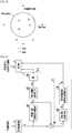
- the inverse transformation using division can ensure stability and causality when z-plane's poles and zeros of the estimated receiving channel are located inside the unit circle as illustrated in Fig. 2 .
- An embodiment of the present invention is directed to providing an apparatus and method for estimating an inverse channel of a repeater's receiving channel, which are capable of solving a problem that has not ensured stability and causality because z-plane's poles and zeros of an estimated receiving channel are located outside the unit circle.
- Another embodiment of the present invention is directed to providing an apparatus and method for estimating an inverse channel of a repeater's receiving channel, which are capable of ensuring stability and causality by estimating a channel established by a transmission path between a transmitter and a repeater from a signal transmitted with a known signal such as a pilot signal or a training sequence being inserted, and generating a time-domain filter coefficient having information on an inverse channel of a repeater's receiving channel from the estimated channel.
- an apparatus for estimating an inverse channel including: a channel estimator for estimating a channel established by a transmission path from a received signal with a known signal being inserted; an inverse minimum phase filter coefficient generator for generating an inverse channel of a minimum phase channel from the channel estimated by the channel estimator, and converting the inverse channel of the minimum phase channel into a time-domain filter coefficient; an inverse group delay filter coefficient generator for generating a time-domain filter coefficient having an inverse group delay component by using the estimated channel divided by the minimum phase channel; and a combiner for generating an inverse channel of a receiving channel in a time domain by combining the filter coefficient converted from the inverse minimum phase filter coefficient generator and the filter coefficient generated from the inverse group delay filter coefficient generator.
- a method for estimating an inverse channel including: estimating a channel established by a transmission path from a received signal with a known signal being inserted; generating an inverse channel of a minimum phase channel from the estimated channel, and converting the inverse channel of the minimum phase channel into a time-domain filter coefficient; generating a time-domain filter coefficient having an inverse group delay component by using the estimated channel divided by the minimum phase channel; and generating an inverse channel of a receiving channel in a time domain by combining the converted filter coefficient and the generated filter coefficient.
- stability and causality can be ensured by estimating a channel established by a transmission path between a transmitter and a repeater from a signal transmitted with a known signal such as a pilot signal or a training sequence being inserted, and generating a time-domain filter coefficient having information on an inverse channel of a repeater's receiving channel from the estimated channel.
- Fig. 4 is a block diagram illustrating an apparatus for estimating an inverse channel of a repeater's receiving channel in accordance with an embodiment of the present invention.
- the apparatus includes a channel estimator 41, an inverse minimum phase filter coefficient generator 42, an inverse group delay filter coefficient generator 43, and a combiner 44.
- the channel estimator 41 estimates a channel H established by a transmission path between a transmitter and a repeater from a signal transmitted with a known signal such as a pilot signal or a training sequence being inserted.
- the inverse minimum phase filter coefficient generator 42 generates an inverse channel H INV,MIN of a minimum phase channel H MIN , where z-plane's poles and zeros are located inside the unit circle, from the channel (H) estimated by the channel estimator 41, and converts the inverse channel H INV,MIN of the minimum phase channel H MIN into a time-domain filter coefficient h inv,min .
- the inverse group delay filter coefficient generator 43 generates a time-domain filter coefficient h inv,ap having an inverse group delay component G AP -1 by using the estimated channel H and the minimum phase channel H MIN .
- the combiner 44 generates an inverse channel of a receiving channel in the time domain by combining the filter coefficient h inv,nin from the inverse minimum phase filter coefficient generator 42 and the filter coefficient h inv,ap from the inverse group delay filter coefficient generator 43.
- the inverse minimum phase coefficient filter coefficient generator 42 includes a minimum phase channel generating unit 421, an inverse channel generating unit 422, and an inverse fast Fourier transform (IFFT) unit 423.
- IFFT inverse fast Fourier transform
- the inverse group delay filter coefficient generator 43 includes a division unit 431, a group delay calculating unit 432, and an inverse group delay coefficient generating unit 433.
- the channel estimator 41 estimates the channel H established by a transmission path between the transmitter and the repeater from the received signal with the known signal such as the pilot signal or the training sequence being inserted.
- the estimated channel H includes a minimum phase component and an all-pass component as expressed in the following Equation 2.
- Equation 2 can be rewritten as the following Equation 3.
- the minimum phase channel generating unit 421 receives the estimated channel H to generate the minimum phase channel H MIN in which the z-plane's poles and zeros are located inside the unit circle.
- the inverse channel generating unit 422 generates the inverse channel H INV,MIN of the generated minimum phase channel H MIN , based on the following Equation 4.
- the inverse transformation using division can be achieved because the z-plane's poles and zeros in the generated minimum phase channel H MIN , are located inside the unit circle, that is, because the stability and causality are ensured.
- the IFFT unit 423 converts the inverse channel H INV,MIN of the frequency-domain minimum phase channel into the time-domain filter coefficient h inv,min .
- the division unit 431 generates the all-pass component H AP of the channel by dividing the estimated channel H by the generated minimum phase channel H MIN , based on the following Equation 5.
- H AP H AP 0 H AP 1 ...
- H AP N ⁇ 1 T H 0 H MIN 0 H 1 H MIN 1 ⁇ H N ⁇ 1 H MIN N ⁇ 1 T
- the group delay calculating unit 432 calculates the group delay component G AP from the phase information of the all-pass component H AP of the channel, based on the following Equation 6.
- G AP ⁇ ⁇ d d ⁇ arg H AP e j ⁇
- arg[ ⁇ ] represents a phase response of an arbitrary system.
- the inverse group delay coefficient generating unit 433 generates a time-domain filter coefficient h inv,ap having an inverse group delay component G AP -1 corresponding to a reciprocal of the calculated group delay component G AP .
- the combiner 44 generates a time-domain inverse channel of the receiving channel by combining the IFFT-ed filter coefficient h inv,min , which is generated by the IFFT unit 423, and the time-domain filter coefficient h inv,ap having the inverse group delay component, which is generated by the inverse group delay coefficient generating unit 433, based on the following Equation 7.
- Equation 7 h inv h inv , min ⁇ h inv , ap where * represents a convolution operation.
- Fig. 5 is a block diagram of the channel estimator in the apparatus for estimating the inverse channel of the repeater's receiving channel in accordance with an embodiment of the present invention.
- the channel estimator includes a reference signal storing unit 50, a known signal extracting unit 51, and a channel distortion estimating unit 52.
- the reference signal storing unit 50 stores a reference signal X used for the distortion estimation of the receiving channel.
- the known signal extracting unit 51 extracts a signal Y known to a transmitting side and a receiving side from the received signal.
- the channel distortion estimating unit 52 estimates the distortion of the receiving channel by comparing the known signal Y extracted by the known signal extracting unit 51 with the reference signal X stored in the reference signal storing unit 50.
- the channel distortion estimating unit 52 estimates the distortion of the receiving channel, based on the following Equation 8.
- Y Y 0 Y 1 ... Y N ⁇ 1 T represents the pilot signal or training signal extracted from the received signal and known to the transmitting side and the receiving side.
- Fig. 6 is a block diagram of the minimum phase channel generating unit in the apparatus for estimating the inverse channel of the repeater's receiving channel in accordance with an embodiment of the present invention.
- the minimum phase channel generating unit includes a logarithmic function unit 61, an IFFT unit 62, a frequency-invariant linear filter coefficient generating unit 63, a multiplication unit 64, an FFT unit 65, and an exponential function unit 66.
- the logarithmic function unit (logarithmic transformation unit) 61 performs a logarithmic transformation on the channel H estimated by the channel estimator 41, based on the following Equation 9.
- the IFFT unit 62 converts the logarithmically converted channel H L into a time-domain coefficient c x .
- the frequency-invariant linear filter coefficient generating unit 63 generates a frequency-invariant linear filter coefficient expressed as the following Equation 10.
- the multiplication unit 64 multiplies the IFFT-ed coefficient c x from the IFFT unit 62 by the frequency-invariant linear filter coefficient l min output from the frequency-invariant linear filter coefficient generating unit 63, based on the following Equation 11.
- the FFT unit 65 converts the coefficient x min output from the multiplication unit 64 into a frequency-domain coefficient x min .
- the exponential function unit (exponential transformation unit) 66 generates the minimum phase channel H MIN by performing an exponential transformation on the FFT-ed coefficient X min, based on the following Equation 12.
- Fig. 7 is a flowchart illustrating a method for estimating an inverse channel of a repeater's receiving channel in accordance with an embodiment of the present invention.
- a channel H established by a transmission path between a transmitter and a repeater is estimated from a signal transmitted with a known signal such as a pilot signal or a training sequence being inserted.
- an inverse channel H INV,MIN of a minimum phase channel H MIN is generated from the estimated channel (H) and is converted into a time-domain filter coefficient h inv,min .
- the minimum phase channel H MIN where the z-plane's poles and zeros are located inside the unit circle is generated from the estimated channel H, and the inverse channel H INV,MIN is generated from the minimum phase channel H MIN .
- the frequency-domain inverse channel H INV,MIN of the minimum phase channel is converted into the time-domain filter coefficient h inv,min .
- a time-domain filter coefficient h inv,ap having an inverse group delay component G AP -1 is generated using the estimated channel H and the minimum phase channel H MIN .
- an all-pass component H AP of the channel is generated by dividing the estimated channel H by the minimum phase channel H MIN , and the group delay component G AP is calculated from phase information of the all-pass component H AP of the channel through differentiation. Then, the time-domain filter coefficient h inv,ap is generated which has an inverse group delay component G AP -1 corresponding to the reciprocal of the calculated group delay component G AP .
- an inverse channel of a receiving channel is generated in the time domain by combining the converted filter coefficient h inv,min and the generated filter coefficient h inv,ap .
- the apparatus for estimating the inverse channel of the repeater's receiving channel is adapted for broadcasting fields, such as ATSC, DVB, DMB and ISDB-T, and communication fields, such as Wibro and CDMA, the present invention is not limited thereto.
- the present invention can be applied to any environment requiring a typical repeater.
- the methods for estimating the inverse channel of the repeater's receiving channel in accordance with the embodiments of the present invention can be realized as a program and stored in a computer-readable recording medium, such as CD-ROM, RAM, ROM, floppy disk, hard disk and magneto-optical disk. Since the process can be easily implemented by those skilled in the art of the present invention, further description will not be provided herein.
Landscapes
- Engineering & Computer Science (AREA)
- Computer Networks & Wireless Communication (AREA)
- Signal Processing (AREA)
- Power Engineering (AREA)
- Physics & Mathematics (AREA)
- Mathematical Physics (AREA)
- Radio Relay Systems (AREA)
- Cable Transmission Systems, Equalization Of Radio And Reduction Of Echo (AREA)
Description
- The present invention relates to an apparatus and method for estimating an inverse channel of a repeater's receiving channel; and, more particularly, to an apparatus and method for estimating an inverse channel of a repeater's receiving channel, which is capable of ensuring stability and causality by generating a time-domain filter coefficient having information on an inverse channel of a repeater's receiving channel from a signal transmitted from a main transmitter or other repeater.
- A repeater is installed in an area where a signal from a main transmitter is received at a weak level, and it can solve an unstable reception and broaden a coverage area of the main transmitter.
- Generally, channel distortion occurs between the main transmitter and the repeater. The repeater compensates for the distortion of a receiving channel between the main transmitter and the repeater and retransmits the compensated signal. To this end, the repeater estimates a receiving channel, generates a time-domain filter coefficient having information on an inverse channel of the estimated receiving channel, and compensates for the distortion of the receiving channel by filtering a received signal using the generated filter coefficient.
- A conventional method for estimating an inverse channel of a repeater's receiving channel will be described below with reference to
Fig. 1 . - Referring to
Fig. 1 , an inverse channel (HINV) 12 is generated from an estimated receiving channel (H) 11 by a direct inverse transformation using division, which is expressed as the following Equation 1:
MathFigure 1
where N represents the number of samples of the estimated channel, and T represents a transpose. - The inverse transformation using division can ensure stability and causality when z-plane's poles and zeros of the estimated receiving channel are located inside the unit circle as illustrated in
Fig. 2 . - However, in the real environment, a part of the z-plane's poles and zeros of the estimated receiving channel are located outside the unit circle as illustrated in
Fig. 3 . Therefore, in the real environment, the channel estimation using division cannot ensure stability and causality. - Document
US 2003-0081308 A1 discloses a method of power transient control in an optical network by power measurement and prediction with a simple-to-compute model to drive and optical filter control wherein a minimum-phase response can be reconstructed from amplitude-only data by using the Complex Cepstrum Analysis. - An embodiment of the present invention is directed to providing an apparatus and method for estimating an inverse channel of a repeater's receiving channel, which are capable of solving a problem that has not ensured stability and causality because z-plane's poles and zeros of an estimated receiving channel are located outside the unit circle.
- Another embodiment of the present invention is directed to providing an apparatus and method for estimating an inverse channel of a repeater's receiving channel, which are capable of ensuring stability and causality by estimating a channel established by a transmission path between a transmitter and a repeater from a signal transmitted with a known signal such as a pilot signal or a training sequence being inserted, and generating a time-domain filter coefficient having information on an inverse channel of a repeater's receiving channel from the estimated channel.
- Other objects and advantages of the present invention can be understood by the following description, and become apparent with reference to the embodiments of the present invention. Also, it is obvious to those skilled in the art of the present invention that the objects and advantages of the present invention can be realized by the means as claimed and combinations thereof.
- The present invention is defined in the independent claims. The dependent claims define advantageous embodiments thereof.
- In accordance with an aspect of the present invention, there is provided an apparatus for estimating an inverse channel, the apparatus including: a channel estimator for estimating a channel established by a transmission path from a received signal with a known signal being inserted; an inverse minimum phase filter coefficient generator for generating an inverse channel of a minimum phase channel from the channel estimated by the channel estimator, and converting the inverse channel of the minimum phase channel into a time-domain filter coefficient; an inverse group delay filter coefficient generator for generating a time-domain filter coefficient having an inverse group delay component by using the estimated channel divided by the minimum phase channel; and a combiner for generating an inverse channel of a receiving channel in a time domain by combining the filter coefficient converted from the inverse minimum phase filter coefficient generator and the filter coefficient generated from the inverse group delay filter coefficient generator.
- In accordance with another aspect of the present invention, there is provided a method for estimating an inverse channel, the method including: estimating a channel established by a transmission path from a received signal with a known signal being inserted; generating an inverse channel of a minimum phase channel from the estimated channel, and converting the inverse channel of the minimum phase channel into a time-domain filter coefficient; generating a time-domain filter coefficient having an inverse group delay component by using the estimated channel divided by the minimum phase channel; and generating an inverse channel of a receiving channel in a time domain by combining the converted filter coefficient and the generated filter coefficient.
- According to the present invention, stability and causality can be ensured by estimating a channel established by a transmission path between a transmitter and a repeater from a signal transmitted with a known signal such as a pilot signal or a training sequence being inserted, and generating a time-domain filter coefficient having information on an inverse channel of a repeater's receiving channel from the estimated channel.
-
-
Fig. 1 is a graph illustrating a repeater's receiving channel and its inverse channel in the frequency domain. -
Fig. 2 is a graph illustrating z-plane's poles and zeros of the repeater's receiving channel, which are located inside the unit circle. -
Fig. 3 is a graph illustrating z-plane's poles and zeros of the repeater's receiving channel, which are located outside the unit circle. -
Fig. 4 is a block diagram showing an apparatus for estimating an inverse channel of a repeater's receiving channel in accordance with an embodiment of the present invention. -
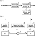
Fig. 5 is a block diagram of a channel estimator in the apparatus for estimating the inverse channel of the repeater's receiving channel in accordance with an embodiment of the present invention. -
Fig. 6 is a block diagram showing a minimum phase channel generating unit in the apparatus for estimating the inverse channel of the repeater's receiving channel in accordance with an embodiment of the present invention. -
Fig. 7 is a flowchart illustrating a method for estimating an inverse channel of a repeater's receiving channel in accordance with an embodiment of the present invention. - The advantages, features and aspects of the invention will become apparent from the following description of the embodiments with reference to the accompanying drawings, which is set forth hereinafter.
-
Fig. 4 is a block diagram illustrating an apparatus for estimating an inverse channel of a repeater's receiving channel in accordance with an embodiment of the present invention. - Referring to
Fig. 4 , the apparatus includes a channel estimator 41, an inverse minimum phasefilter coefficient generator 42, an inverse group delay filter coefficient generator 43, and acombiner 44. The channel estimator 41 estimates a channel H established by a transmission path between a transmitter and a repeater from a signal transmitted with a known signal such as a pilot signal or a training sequence being inserted. - The inverse minimum phase
filter coefficient generator 42 generates an inverse channel HINV,MIN of a minimum phase channel HMIN, where z-plane's poles and zeros are located inside the unit circle, from the channel (H) estimated by the channel estimator 41, and converts the inverse channel HINV,MIN of the minimum phase channel HMIN into a time-domain filter coefficient hinv,min. - The inverse group delay filter coefficient generator 43 generates a time-domain filter coefficient hinv,ap having an inverse group delay component GAP -1 by using the estimated channel H and the minimum phase channel HMIN. The
combiner 44 generates an inverse channel of a receiving channel in the time domain by combining the filter coefficient hinv,nin from the inverse minimum phasefilter coefficient generator 42 and the filter coefficient hinv,ap from the inverse group delay filter coefficient generator 43. - The inverse minimum phase coefficient
filter coefficient generator 42 includes a minimum phasechannel generating unit 421, an inversechannel generating unit 422, and an inverse fast Fourier transform (IFFT) unit 423. - The inverse group delay filter coefficient generator 43 includes a division unit 431, a group
delay calculating unit 432, and an inverse group delay coefficient generating unit 433. - The respective elements of the apparatus for estimating the inverse channel of the repeater's receiving channel in accordance with the embodiment of the present invention will be described below in detail.
- The channel estimator 41 estimates the channel H established by a transmission path between the transmitter and the repeater from the received signal with the known signal such as the pilot signal or the training sequence being inserted. The estimated channel H includes a minimum phase component and an all-pass component as expressed in the following Equation 2.
MathFigure 2
- Equation 2 can be rewritten as the following Equation 3.
MathFigure 3
where - HMIN(i)
represents the minimum phase component of the channel, and - HAP(i)
represents the all-pass component of the channel. - The minimum phase
channel generating unit 421 receives the estimated channel H to generate the minimum phase channel HMIN in which the z-plane's poles and zeros are located inside the unit circle. - The inverse
channel generating unit 422 generates the inverse channel HINV,MIN of the generated minimum phase channel HMIN, based on the following Equation 4.
MathFigure 4
- The inverse transformation using division can be achieved because the z-plane's poles and zeros in the generated minimum phase channel HMIN, are located inside the unit circle, that is, because the stability and causality are ensured.
- The IFFT unit 423 converts the inverse channel HINV,MIN of the frequency-domain minimum phase channel into the time-domain filter coefficient hinv,min.
- The division unit 431 generates the all-pass component HAP of the channel by dividing the estimated channel H by the generated minimum phase channel HMIN, based on the following Equation 5.
MathFigure 5
- The group
delay calculating unit 432 calculates the group delay component GAP from the phase information of the all-pass component HAP of the channel, based on the following Equation 6.
MathFigure 6
where
arg[·]
represents a phase response of an arbitrary system. - The inverse group delay coefficient generating unit 433 generates a time-domain filter coefficient hinv,ap having an inverse group delay component GAP -1 corresponding to a reciprocal of the calculated group delay component GAP.
- The
combiner 44 generates a time-domain inverse channel of the receiving channel by combining the IFFT-ed filter coefficient hinv,min, which is generated by the IFFT unit 423, and the time-domain filter coefficient hinv,ap having the inverse group delay component, which is generated by the inverse group delay coefficient generating unit 433, based on the following Equation 7.
MathFigure 7
where * represents a convolution operation. -
Fig. 5 is a block diagram of the channel estimator in the apparatus for estimating the inverse channel of the repeater's receiving channel in accordance with an embodiment of the present invention. - Referring to
Fig. 5 , the channel estimator includes a referencesignal storing unit 50, a knownsignal extracting unit 51, and a channeldistortion estimating unit 52. The referencesignal storing unit 50 stores a reference signal X used for the distortion estimation of the receiving channel. - The known
signal extracting unit 51 extracts a signal Y known to a transmitting side and a receiving side from the received signal. The channeldistortion estimating unit 52 estimates the distortion of the receiving channel by comparing the known signal Y extracted by the knownsignal extracting unit 51 with the reference signal X stored in the referencesignal storing unit 50. - The channel
distortion estimating unit 52 estimates the distortion of the receiving channel, based on the following Equation 8.
MathFigure 8
where


-
Fig. 6 is a block diagram of the minimum phase channel generating unit in the apparatus for estimating the inverse channel of the repeater's receiving channel in accordance with an embodiment of the present invention. - Referring to
Fig. 6 , the minimum phase channel generating unit includes alogarithmic function unit 61, anIFFT unit 62, a frequency-invariant linear filtercoefficient generating unit 63, amultiplication unit 64, anFFT unit 65, and anexponential function unit 66. - The respective elements of the minimum phase channel generating unit will be described below in more detail.
- The logarithmic function unit (logarithmic transformation unit) 61 performs a logarithmic transformation on the channel H estimated by the channel estimator 41, based on the following Equation 9.
MathFigure 9
where
- The
IFFT unit 62 converts the logarithmically converted channel HL into a time-domain coefficient cx. - The frequency-invariant linear filter
coefficient generating unit 63 generates a frequency-invariant linear filter coefficient expressed as the following Equation 10.
MathFigure 10
- The
multiplication unit 64 multiplies the IFFT-ed coefficient cx from theIFFT unit 62 by the frequency-invariant linear filter coefficient lmin output from the frequency-invariant linear filtercoefficient generating unit 63, based on the followingEquation 11.
MathFigure 11
where
- The
FFT unit 65 converts the coefficient xmin output from themultiplication unit 64 into a frequency-domain coefficient xmin. - The exponential function unit (exponential transformation unit) 66 generates the minimum phase channel HMIN by performing an exponential transformation on the FFT-ed coefficient Xmin, based on the following
Equation 12.
MathFigure 12
-
Fig. 7 is a flowchart illustrating a method for estimating an inverse channel of a repeater's receiving channel in accordance with an embodiment of the present invention. - In operation S701, a channel H established by a transmission path between a transmitter and a repeater is estimated from a signal transmitted with a known signal such as a pilot signal or a training sequence being inserted.
- In operation S702, an inverse channel HINV,MIN of a minimum phase channel HMIN, where z-plane's poles and zeros are located inside the unit circle, is generated from the estimated channel (H) and is converted into a time-domain filter coefficient hinv,min.
- That is, the minimum phase channel HMIN where the z-plane's poles and zeros are located inside the unit circle is generated from the estimated channel H, and the inverse channel HINV,MIN is generated from the minimum phase channel HMIN. Then, the frequency-domain inverse channel HINV,MIN of the minimum phase channel is converted into the time-domain filter coefficient hinv,min.
- In operation S703, a time-domain filter coefficient hinv,ap having an inverse group delay component GAP -1 is generated using the estimated channel H and the minimum phase channel HMIN.
- That is, an all-pass component HAP of the channel is generated by dividing the estimated channel H by the minimum phase channel HMIN, and the group delay component GAP is calculated from phase information of the all-pass component HAP of the channel through differentiation. Then, the time-domain filter coefficient hinv,ap is generated which has an inverse group delay component GAP -1 corresponding to the reciprocal of the calculated group delay component GAP.
- In operation S704, an inverse channel of a receiving channel is generated in the time domain by combining the converted filter coefficient hinv,min and the generated filter coefficient hinv,ap.
- Although the apparatus for estimating the inverse channel of the repeater's receiving channel according to the present invention is adapted for broadcasting fields, such as ATSC, DVB, DMB and ISDB-T, and communication fields, such as Wibro and CDMA, the present invention is not limited thereto. The present invention can be applied to any environment requiring a typical repeater.
- The methods for estimating the inverse channel of the repeater's receiving channel in accordance with the embodiments of the present invention can be realized as a program and stored in a computer-readable recording medium, such as CD-ROM, RAM, ROM, floppy disk, hard disk and magneto-optical disk. Since the process can be easily implemented by those skilled in the art of the present invention, further description will not be provided herein.
- While the present invention has been described with respect to the specific embodiments, it will be apparent to those skilled in the art that various changes and modifications may be made without departing from the scope of the invention as defined in the following claims.
Claims (12)
- An apparatus for estimating an inverse channel, the apparatus comprising: a channel estimator (41) for estimating a channel established by a transmission path from a received signal with a known signal being inserted; an inverse minimum phase filter coefficient generator (42) for generating an inverse channel of a minimum phase channel from the channel estimated by the channel estimator, and converting the inverse channel of the minimum phase channel into a time-domain filter coefficient; an inverse group delay filter coefficient generator (43) for generating a time-domain filter coefficient having an inverse group delay component by using the estimated channel divided by the minimum phase channel; and a combiner (44) for generating an inverse channel of a receiving channel in a time domain by combining the filter coefficient converted from the inverse minimum phase filter coefficient generator and the filter coefficient generated from the inverse group delay filter coefficient generator.
- The apparatus of claim 1, wherein the inverse minimum phase coefficient filter coefficient generator (42) comprises: a minimum phase channel generating unit (421) for receiving the channel estimated by the channel estimator to generate the minimum phase channel in which z-plane's poles and zeros are located inside a unit circle; an inverse channel generating unit (422) for generating the inverse channel of the minimum phase channel generated by the minimum phase channel generating unit; and an inverse fast Fourier transform, IFFT, unit (423) for converting a frequency-domain inverse channel of the minimum phase channel from the inverse channel generating unit into the time-domain filter coefficient.
- The apparatus of claim 2, wherein the minimum phase channel generating unit (421) comprises: a logarithmic transformation unit (61) for performing a logarithmic transformation on the channel estimated by the channel estimator (41); a second IFFT unit (62) for converting the channel transformed by the logarithmic transformation unit into a time-domain coefficient; a linear filter coefficient generating unit (63) for generating a frequency-invariant linear filter coefficient; a multiplication unit (64) for multiplying the coefficient converted by the second IFFT unit (62) by the frequency-invariant linear filter coefficient generated from the linear filter coefficient generating unit (63); a fast Fourier transform, FFT, unit (65) for converting the coefficient output from the multiplication unit into a frequency-domain coefficient; and an exponential transformation unit (66) for generating the minimum phase channel by performing an exponential transformation on the coefficient converted by the FFT unit (65).
- The apparatus of claim 1, wherein the inverse group delay filter coefficient generator (43) comprises: an all-pass component generating unit for generating an all-pass component of the channel by dividing the estimated channel by the minimum phase channel; a group delay calculating unit (432) for calculating the group delay component from phase information of the all-pass component of the channel, which is generated by the all-pass component generating unit; and an inverse group delay coefficient generating unit (433) for generating a time-domain filter coefficient having an inverse group delay component corresponding to a reciprocal of the group delay component calculated by the group delay calculating unit.
- The apparatus of claim 4, wherein the channel estimator (41) comprises: a reference signal storing unit (50) for storing a reference signal used to estimate distortion of the receiving channel; an extracting unit (51) for extracting a distortion estimation signal from the received signal; and a channel distortion estimating unit (52) for estimating the distortion of the receiving channel by comparing the distortion estimation signal extracted by the distortion estimation signal with the reference signal stored in the reference signal storing unit (50).
- The apparatus of claim 4, wherein the known signal comprises a pilot signal or a training sequence.
- A method for estimating an inverse channel, the method comprising: estimating a channel established by a transmission path from a received signal with a known signal being inserted (S701); generating an inverse channel of a minimum phase channel from the estimated channel, and converting the inverse channel of the minimum phase channel into a time-domain filter coefficient (S702); generating a time-domain filter coefficient having an inverse group delay component by using the estimated channel divided by the minimum phase channel (S703); and generating an inverse channel of a receiving channel in a time domain by combining the converted filter coefficient and the generated filter coefficient (S704).
- The method of claim 7, wherein said generating of the inverse channel of the minimum phase channel comprises: generating the minimum phase channel, where z-plane's poles and zeros are located inside a unit circle, from the estimated channel; generating the inverse channel of the generated minimum phase channel; and converting the generated frequency-domain inverse channel of the minimum phase channel into the time-domain filter coefficient.
- The methods of claim 8, wherein said generating of the minimum phase channel comprises: performing a logarithmic transformation on the estimated channel; converting the logarithmic-transformed channel into a time-domain coefficient; generating a frequency-invariant linear filter coefficient; multiplying the converted time-domain coefficient by the generated frequency- invariant linear filter coefficient; converting the multiplication result into a frequency-domain coefficient; and generating the minimum phase channel by performing an exponential transformation on the converted frequency-domain coefficient.
- The method of claim 7, wherein said generating of the time-domain filter coefficient comprises: generating an all-pass component of the channel by dividing the estimated channel by the minimum phase channel; calculating the group delay component from phase information of the all-pass component of the channel; and generating a time-domain filter coefficient having an inverse group delay component corresponding to a reciprocal of the calculated group delay component.
- The method of claim 10, wherein said estimating of the channel comprises: storing a reference signal used to estimate distortion of the receiving channel; extracting a distortion estimation signal from the received signal; and estimating distortion of the receiving channel by comparing the extracted distortion estimation signal with the stored reference signal.
- The method of claim 10, wherein the known signal comprises a pilot signal or a training sequence.
Applications Claiming Priority (2)
| Application Number | Priority Date | Filing Date | Title |
|---|---|---|---|
| KR1020070091034A KR100923157B1 (en) | 2007-09-07 | 2007-09-07 | Reverse Channel Estimation Apparatus and Method for Repeater Receiving Channel |
| PCT/KR2008/002534 WO2009031746A1 (en) | 2007-09-07 | 2008-05-06 | Apparatus and method for estimating inverse channel of repeater's receiving channel |
Publications (3)
| Publication Number | Publication Date |
|---|---|
| EP2188915A1 EP2188915A1 (en) | 2010-05-26 |
| EP2188915A4 EP2188915A4 (en) | 2015-11-11 |
| EP2188915B1 true EP2188915B1 (en) | 2018-08-15 |
Family
ID=40429042
Family Applications (1)
| Application Number | Title | Priority Date | Filing Date |
|---|---|---|---|
| EP08753331.1A Not-in-force EP2188915B1 (en) | 2007-09-07 | 2008-05-06 | Apparatus and method for estimating inverse channel of repeater's receiving channel |
Country Status (5)
| Country | Link |
|---|---|
| US (1) | US8411801B2 (en) |
| EP (1) | EP2188915B1 (en) |
| JP (1) | JP4971503B2 (en) |
| KR (1) | KR100923157B1 (en) |
| WO (1) | WO2009031746A1 (en) |
Families Citing this family (6)
| Publication number | Priority date | Publication date | Assignee | Title |
|---|---|---|---|---|
| US9049065B2 (en) * | 2009-05-11 | 2015-06-02 | Qualcomm Incorporated | Removal of ICI/ISI errors in frequency domain channel estimation for wireless repeaters |
| US8611227B2 (en) | 2009-05-11 | 2013-12-17 | Qualcomm Incorporated | Channel estimate pruning in presence of large signal dynamics in an interference cancellation repeater |
| US20110116531A1 (en) * | 2009-05-11 | 2011-05-19 | Qualcomm Incorporated | Removal of multiplicative errors in frequency domain channel estimation for wireless repeaters |
| WO2016179333A1 (en) * | 2015-05-06 | 2016-11-10 | Ping Liang | Wireless repeater with fir based channel equalizer |
| JP6611673B2 (en) * | 2016-06-08 | 2019-11-27 | 三菱電機株式会社 | Reception device, reception method, and transmission / reception system |
| WO2023106977A1 (en) * | 2021-12-07 | 2023-06-15 | Telefonaktiebolaget Lm Ericsson (Publ) | Receiver node and method in a wireless communications network |
Family Cites Families (16)
| Publication number | Priority date | Publication date | Assignee | Title |
|---|---|---|---|---|
| US3466547A (en) | 1967-04-18 | 1969-09-09 | Bell Telephone Labor Inc | Method for reducing the distortion of multipath transmissions |
| JPS63246914A (en) | 1987-04-02 | 1988-10-13 | Matsushita Electric Ind Co Ltd | How to set filter coefficient calculation |
| CA1280808C (en) | 1987-03-23 | 1991-02-26 | Seiichi Ishikawa | Calculation of filter factors for digital filter |
| US5282154A (en) | 1992-06-01 | 1994-01-25 | Thomson Consumer Electronics, Inc. | System for determining and repairing instability in an IIR filter suitable for use in deghosting apparatus |
| GB2287620B (en) * | 1994-03-10 | 1998-12-16 | Roke Manor Research | A digital cellular mobile radio receiver |
| DE60022012D1 (en) | 2000-06-08 | 2005-09-22 | St Microelectronics Nv | Equalizer, using a channel conversion. |
| US6965470B2 (en) * | 2001-08-20 | 2005-11-15 | Texas Instruments Incorporated | Adaptive control of power transients |
| KR100463544B1 (en) * | 2002-12-14 | 2004-12-29 | 엘지전자 주식회사 | Channel equalizer and digital TV receiver using for the same |
| KR100651710B1 (en) * | 2003-09-08 | 2006-11-30 | 송성준 | Apparatus and method for monitoring call state in mobile communication system, and recording medium storing program implementing the method |
| KR100576161B1 (en) * | 2004-08-20 | 2006-05-03 | 주식회사 컨버시스 | Relay method and apparatus with call statistical analysis |
| KR100770924B1 (en) * | 2005-02-04 | 2007-10-26 | 삼성전자주식회사 | Frequency Error Compensation Device and Method in Wireless Communication System |
| WO2006104408A1 (en) * | 2005-03-31 | 2006-10-05 | Intel Corporation | System and method for compensation of non-linear transmitter distortion |
| WO2006115320A1 (en) | 2005-04-25 | 2006-11-02 | Electronics And Telecommunications Research Institute | Apparatus and method of on-channel repeater |
| KR101179483B1 (en) * | 2006-01-12 | 2012-09-07 | 에스케이텔레콤 주식회사 | Repeater call counter for analyzing cell loading and counting method thereof |
| JP4286840B2 (en) | 2006-02-08 | 2009-07-01 | 学校法人早稲田大学 | Impulse response synthesis method and reverberation method |
| JP5460057B2 (en) * | 2006-02-21 | 2014-04-02 | ウルフソン・ダイナミック・ヒアリング・ピーティーワイ・リミテッド | Low delay processing method and method |
-
2007
- 2007-09-07 KR KR1020070091034A patent/KR100923157B1/en active Active
-
2008
- 2008-05-06 WO PCT/KR2008/002534 patent/WO2009031746A1/en not_active Ceased
- 2008-05-06 JP JP2010523929A patent/JP4971503B2/en not_active Expired - Fee Related
- 2008-05-06 US US12/676,883 patent/US8411801B2/en active Active
- 2008-05-06 EP EP08753331.1A patent/EP2188915B1/en not_active Not-in-force
Non-Patent Citations (1)
| Title |
|---|
| None * |
Also Published As
| Publication number | Publication date |
|---|---|
| EP2188915A4 (en) | 2015-11-11 |
| US8411801B2 (en) | 2013-04-02 |
| JP4971503B2 (en) | 2012-07-11 |
| JP2010538566A (en) | 2010-12-09 |
| US20100310023A1 (en) | 2010-12-09 |
| WO2009031746A1 (en) | 2009-03-12 |
| KR100923157B1 (en) | 2009-10-23 |
| EP2188915A1 (en) | 2010-05-26 |
| KR20090025874A (en) | 2009-03-11 |
Similar Documents
| Publication | Publication Date | Title |
|---|---|---|
| US10104666B2 (en) | Method and system for compensating for doubly selective channel and related apparatus | |
| Qu et al. | A journey toward modeling and resolving doppler in underwater acoustic communications | |
| CN103095639B (en) | Orthogonal frequency division multiplexing (OFDM) underwater acoustic communication parallel iterative inter-carrier interference (ICI) elimination method | |
| EP1507375B1 (en) | A feedback-type channel estimation method and a device based on a PN sequence and a pilot frequency in an OFDM system | |
| EP2437451A1 (en) | Method, terminal and system for implementing coordinated multi-point transmission | |
| EP2228955B1 (en) | System and method for OFDM reception in the presense of Doppler effect based on time domain windowing | |
| EP2151107B1 (en) | Receiver for a radio network and an method for determining a channel estimate for a radio channel | |
| US20100046599A1 (en) | Apparatus and method for acquiring initial coefficient of decision feedback equalizer using fast fourier transform | |
| CN101534266A (en) | Channel estimation method for Orthogonal Frequency Division Multiplexing system and device thereof | |
| US8411801B2 (en) | Apparatus and method for estimating inverse channel of repeater's receiving channel | |
| CN102647387A (en) | Same frequency interference elimination method and device | |
| CN104539562A (en) | MIMO-OFDM wideband HF channel estimation method | |
| EP2259465A1 (en) | Mimo reception device and method | |
| CN101375521A (en) | Transmission path estimation device, equalisation device, and radio system | |
| US8243836B2 (en) | Channel estimation apparatus and method in mobile communication system having dispersed pilot | |
| CN102215184B (en) | Method and system for estimating uplink timing error | |
| CN102130864A (en) | Channel estimation method and device | |
| CN101216552B (en) | Phase difference estimation method and apparatus | |
| US8385478B1 (en) | Channel estimation method and device using the same | |
| CN101588193A (en) | A transmission path estimation apparatus and method | |
| CN101480007A (en) | Receiver, transmitter, transmission system, and transmission method | |
| EP1819116B1 (en) | Channel estimator and method for channel estimation | |
| JP2008028515A (en) | Receiver, receiving method, and program | |
| CN102447654A (en) | Low-complexity and high-performance channel estimating method and device | |
| US9166829B2 (en) | Method for estimating a radio channel |
Legal Events
| Date | Code | Title | Description |
|---|---|---|---|
| PUAI | Public reference made under article 153(3) epc to a published international application that has entered the european phase |
Free format text: ORIGINAL CODE: 0009012 |
|
| 17P | Request for examination filed |
Effective date: 20100329 |
|
| AK | Designated contracting states |
Kind code of ref document: A1 Designated state(s): AT BE BG CH CY CZ DE DK EE ES FI FR GB GR HR HU IE IS IT LI LT LU LV MC MT NL NO PL PT RO SE SI SK TR |
|
| AX | Request for extension of the european patent |
Extension state: AL BA MK RS |
|
| DAX | Request for extension of the european patent (deleted) | ||
| RA4 | Supplementary search report drawn up and despatched (corrected) |
Effective date: 20151009 |
|
| RIC1 | Information provided on ipc code assigned before grant |
Ipc: H04B 7/26 20060101AFI20151005BHEP Ipc: H04B 7/155 20060101ALI20151005BHEP Ipc: H04L 25/02 20060101ALI20151005BHEP |
|
| GRAP | Despatch of communication of intention to grant a patent |
Free format text: ORIGINAL CODE: EPIDOSNIGR1 |
|
| STAA | Information on the status of an ep patent application or granted ep patent |
Free format text: STATUS: GRANT OF PATENT IS INTENDED |
|
| INTG | Intention to grant announced |
Effective date: 20180223 |
|
| GRAS | Grant fee paid |
Free format text: ORIGINAL CODE: EPIDOSNIGR3 |
|
| GRAA | (expected) grant |
Free format text: ORIGINAL CODE: 0009210 |
|
| STAA | Information on the status of an ep patent application or granted ep patent |
Free format text: STATUS: THE PATENT HAS BEEN GRANTED |
|
| AK | Designated contracting states |
Kind code of ref document: B1 Designated state(s): AT BE BG CH CY CZ DE DK EE ES FI FR GB GR HR HU IE IS IT LI LT LU LV MC MT NL NO PL PT RO SE SI SK TR |
|
| REG | Reference to a national code |
Ref country code: CH Ref legal event code: EP Ref country code: GB Ref legal event code: FG4D Ref country code: AT Ref legal event code: REF Ref document number: 1030976 Country of ref document: AT Kind code of ref document: T Effective date: 20180815 |
|
| REG | Reference to a national code |
Ref country code: IE Ref legal event code: FG4D |
|
| REG | Reference to a national code |
Ref country code: DE Ref legal event code: R096 Ref document number: 602008056498 Country of ref document: DE |
|
| REG | Reference to a national code |
Ref country code: NL Ref legal event code: MP Effective date: 20180815 |
|
| REG | Reference to a national code |
Ref country code: LT Ref legal event code: MG4D |
|
| REG | Reference to a national code |
Ref country code: AT Ref legal event code: MK05 Ref document number: 1030976 Country of ref document: AT Kind code of ref document: T Effective date: 20180815 |
|
| PG25 | Lapsed in a contracting state [announced via postgrant information from national office to epo] |
Ref country code: BG Free format text: LAPSE BECAUSE OF FAILURE TO SUBMIT A TRANSLATION OF THE DESCRIPTION OR TO PAY THE FEE WITHIN THE PRESCRIBED TIME-LIMIT Effective date: 20181115 Ref country code: NL Free format text: LAPSE BECAUSE OF FAILURE TO SUBMIT A TRANSLATION OF THE DESCRIPTION OR TO PAY THE FEE WITHIN THE PRESCRIBED TIME-LIMIT Effective date: 20180815 Ref country code: LT Free format text: LAPSE BECAUSE OF FAILURE TO SUBMIT A TRANSLATION OF THE DESCRIPTION OR TO PAY THE FEE WITHIN THE PRESCRIBED TIME-LIMIT Effective date: 20180815 Ref country code: AT Free format text: LAPSE BECAUSE OF FAILURE TO SUBMIT A TRANSLATION OF THE DESCRIPTION OR TO PAY THE FEE WITHIN THE PRESCRIBED TIME-LIMIT Effective date: 20180815 Ref country code: IS Free format text: LAPSE BECAUSE OF FAILURE TO SUBMIT A TRANSLATION OF THE DESCRIPTION OR TO PAY THE FEE WITHIN THE PRESCRIBED TIME-LIMIT Effective date: 20181215 Ref country code: GR Free format text: LAPSE BECAUSE OF FAILURE TO SUBMIT A TRANSLATION OF THE DESCRIPTION OR TO PAY THE FEE WITHIN THE PRESCRIBED TIME-LIMIT Effective date: 20181116 Ref country code: SE Free format text: LAPSE BECAUSE OF FAILURE TO SUBMIT A TRANSLATION OF THE DESCRIPTION OR TO PAY THE FEE WITHIN THE PRESCRIBED TIME-LIMIT Effective date: 20180815 Ref country code: NO Free format text: LAPSE BECAUSE OF FAILURE TO SUBMIT A TRANSLATION OF THE DESCRIPTION OR TO PAY THE FEE WITHIN THE PRESCRIBED TIME-LIMIT Effective date: 20181115 Ref country code: FI Free format text: LAPSE BECAUSE OF FAILURE TO SUBMIT A TRANSLATION OF THE DESCRIPTION OR TO PAY THE FEE WITHIN THE PRESCRIBED TIME-LIMIT Effective date: 20180815 |
|
| PG25 | Lapsed in a contracting state [announced via postgrant information from national office to epo] |
Ref country code: ES Free format text: LAPSE BECAUSE OF FAILURE TO SUBMIT A TRANSLATION OF THE DESCRIPTION OR TO PAY THE FEE WITHIN THE PRESCRIBED TIME-LIMIT Effective date: 20180815 Ref country code: HR Free format text: LAPSE BECAUSE OF FAILURE TO SUBMIT A TRANSLATION OF THE DESCRIPTION OR TO PAY THE FEE WITHIN THE PRESCRIBED TIME-LIMIT Effective date: 20180815 Ref country code: LV Free format text: LAPSE BECAUSE OF FAILURE TO SUBMIT A TRANSLATION OF THE DESCRIPTION OR TO PAY THE FEE WITHIN THE PRESCRIBED TIME-LIMIT Effective date: 20180815 |
|
| PG25 | Lapsed in a contracting state [announced via postgrant information from national office to epo] |
Ref country code: PL Free format text: LAPSE BECAUSE OF FAILURE TO SUBMIT A TRANSLATION OF THE DESCRIPTION OR TO PAY THE FEE WITHIN THE PRESCRIBED TIME-LIMIT Effective date: 20180815 Ref country code: EE Free format text: LAPSE BECAUSE OF FAILURE TO SUBMIT A TRANSLATION OF THE DESCRIPTION OR TO PAY THE FEE WITHIN THE PRESCRIBED TIME-LIMIT Effective date: 20180815 Ref country code: IT Free format text: LAPSE BECAUSE OF FAILURE TO SUBMIT A TRANSLATION OF THE DESCRIPTION OR TO PAY THE FEE WITHIN THE PRESCRIBED TIME-LIMIT Effective date: 20180815 Ref country code: CZ Free format text: LAPSE BECAUSE OF FAILURE TO SUBMIT A TRANSLATION OF THE DESCRIPTION OR TO PAY THE FEE WITHIN THE PRESCRIBED TIME-LIMIT Effective date: 20180815 Ref country code: RO Free format text: LAPSE BECAUSE OF FAILURE TO SUBMIT A TRANSLATION OF THE DESCRIPTION OR TO PAY THE FEE WITHIN THE PRESCRIBED TIME-LIMIT Effective date: 20180815 |
|
| REG | Reference to a national code |
Ref country code: DE Ref legal event code: R097 Ref document number: 602008056498 Country of ref document: DE |
|
| PG25 | Lapsed in a contracting state [announced via postgrant information from national office to epo] |
Ref country code: SK Free format text: LAPSE BECAUSE OF FAILURE TO SUBMIT A TRANSLATION OF THE DESCRIPTION OR TO PAY THE FEE WITHIN THE PRESCRIBED TIME-LIMIT Effective date: 20180815 Ref country code: DK Free format text: LAPSE BECAUSE OF FAILURE TO SUBMIT A TRANSLATION OF THE DESCRIPTION OR TO PAY THE FEE WITHIN THE PRESCRIBED TIME-LIMIT Effective date: 20180815 |
|
| PLBE | No opposition filed within time limit |
Free format text: ORIGINAL CODE: 0009261 |
|
| STAA | Information on the status of an ep patent application or granted ep patent |
Free format text: STATUS: NO OPPOSITION FILED WITHIN TIME LIMIT |
|
| 26N | No opposition filed |
Effective date: 20190516 |
|
| PG25 | Lapsed in a contracting state [announced via postgrant information from national office to epo] |
Ref country code: SI Free format text: LAPSE BECAUSE OF FAILURE TO SUBMIT A TRANSLATION OF THE DESCRIPTION OR TO PAY THE FEE WITHIN THE PRESCRIBED TIME-LIMIT Effective date: 20180815 |
|
| REG | Reference to a national code |
Ref country code: CH Ref legal event code: PL |
|
| GBPC | Gb: european patent ceased through non-payment of renewal fee |
Effective date: 20190506 |
|
| PG25 | Lapsed in a contracting state [announced via postgrant information from national office to epo] |
Ref country code: MC Free format text: LAPSE BECAUSE OF FAILURE TO SUBMIT A TRANSLATION OF THE DESCRIPTION OR TO PAY THE FEE WITHIN THE PRESCRIBED TIME-LIMIT Effective date: 20180815 Ref country code: LI Free format text: LAPSE BECAUSE OF NON-PAYMENT OF DUE FEES Effective date: 20190531 Ref country code: CH Free format text: LAPSE BECAUSE OF NON-PAYMENT OF DUE FEES Effective date: 20190531 |
|
| REG | Reference to a national code |
Ref country code: BE Ref legal event code: MM Effective date: 20190531 |
|
| PG25 | Lapsed in a contracting state [announced via postgrant information from national office to epo] |
Ref country code: LU Free format text: LAPSE BECAUSE OF NON-PAYMENT OF DUE FEES Effective date: 20190506 |
|
| PG25 | Lapsed in a contracting state [announced via postgrant information from national office to epo] |
Ref country code: TR Free format text: LAPSE BECAUSE OF FAILURE TO SUBMIT A TRANSLATION OF THE DESCRIPTION OR TO PAY THE FEE WITHIN THE PRESCRIBED TIME-LIMIT Effective date: 20180815 |
|
| PG25 | Lapsed in a contracting state [announced via postgrant information from national office to epo] |
Ref country code: GB Free format text: LAPSE BECAUSE OF NON-PAYMENT OF DUE FEES Effective date: 20190506 Ref country code: IE Free format text: LAPSE BECAUSE OF NON-PAYMENT OF DUE FEES Effective date: 20190506 |
|
| PG25 | Lapsed in a contracting state [announced via postgrant information from national office to epo] |
Ref country code: BE Free format text: LAPSE BECAUSE OF NON-PAYMENT OF DUE FEES Effective date: 20190531 |
|
| PG25 | Lapsed in a contracting state [announced via postgrant information from national office to epo] |
Ref country code: FR Free format text: LAPSE BECAUSE OF NON-PAYMENT OF DUE FEES Effective date: 20190531 Ref country code: PT Free format text: LAPSE BECAUSE OF FAILURE TO SUBMIT A TRANSLATION OF THE DESCRIPTION OR TO PAY THE FEE WITHIN THE PRESCRIBED TIME-LIMIT Effective date: 20181215 |
|
| PG25 | Lapsed in a contracting state [announced via postgrant information from national office to epo] |
Ref country code: CY Free format text: LAPSE BECAUSE OF FAILURE TO SUBMIT A TRANSLATION OF THE DESCRIPTION OR TO PAY THE FEE WITHIN THE PRESCRIBED TIME-LIMIT Effective date: 20180815 |
|
| PG25 | Lapsed in a contracting state [announced via postgrant information from national office to epo] |
Ref country code: MT Free format text: LAPSE BECAUSE OF FAILURE TO SUBMIT A TRANSLATION OF THE DESCRIPTION OR TO PAY THE FEE WITHIN THE PRESCRIBED TIME-LIMIT Effective date: 20180815 Ref country code: HU Free format text: LAPSE BECAUSE OF FAILURE TO SUBMIT A TRANSLATION OF THE DESCRIPTION OR TO PAY THE FEE WITHIN THE PRESCRIBED TIME-LIMIT; INVALID AB INITIO Effective date: 20080506 |
|
| PGFP | Annual fee paid to national office [announced via postgrant information from national office to epo] |
Ref country code: DE Payment date: 20230420 Year of fee payment: 16 |
|
| REG | Reference to a national code |
Ref country code: DE Ref legal event code: R119 Ref document number: 602008056498 Country of ref document: DE |
|
| PG25 | Lapsed in a contracting state [announced via postgrant information from national office to epo] |
Ref country code: DE Free format text: LAPSE BECAUSE OF NON-PAYMENT OF DUE FEES Effective date: 20241203 |