EP2188526B1 - Methods for manufacturing pump-heads having a desired internal clearance for rotary member - Google Patents
Methods for manufacturing pump-heads having a desired internal clearance for rotary member Download PDFInfo
- Publication number
- EP2188526B1 EP2188526B1 EP08799004.0A EP08799004A EP2188526B1 EP 2188526 B1 EP2188526 B1 EP 2188526B1 EP 08799004 A EP08799004 A EP 08799004A EP 2188526 B1 EP2188526 B1 EP 2188526B1
- Authority
- EP
- European Patent Office
- Prior art keywords
- pump
- cavity
- rotary member
- housing portions
- clearance
- Prior art date
- Legal status (The legal status is an assumption and is not a legal conclusion. Google has not performed a legal analysis and makes no representation as to the accuracy of the status listed.)
- Active
Links
Images


Classifications
-
- F—MECHANICAL ENGINEERING; LIGHTING; HEATING; WEAPONS; BLASTING
- F04—POSITIVE - DISPLACEMENT MACHINES FOR LIQUIDS; PUMPS FOR LIQUIDS OR ELASTIC FLUIDS
- F04C—ROTARY-PISTON, OR OSCILLATING-PISTON, POSITIVE-DISPLACEMENT MACHINES FOR LIQUIDS; ROTARY-PISTON, OR OSCILLATING-PISTON, POSITIVE-DISPLACEMENT PUMPS
- F04C2/00—Rotary-piston machines or pumps
- F04C2/08—Rotary-piston machines or pumps of intermeshing-engagement type, i.e. with engagement of co-operating members similar to that of toothed gearing
- F04C2/12—Rotary-piston machines or pumps of intermeshing-engagement type, i.e. with engagement of co-operating members similar to that of toothed gearing of other than internal-axis type
- F04C2/14—Rotary-piston machines or pumps of intermeshing-engagement type, i.e. with engagement of co-operating members similar to that of toothed gearing of other than internal-axis type with toothed rotary pistons
- F04C2/18—Rotary-piston machines or pumps of intermeshing-engagement type, i.e. with engagement of co-operating members similar to that of toothed gearing of other than internal-axis type with toothed rotary pistons with similar tooth forms
-
- F—MECHANICAL ENGINEERING; LIGHTING; HEATING; WEAPONS; BLASTING
- F04—POSITIVE - DISPLACEMENT MACHINES FOR LIQUIDS; PUMPS FOR LIQUIDS OR ELASTIC FLUIDS
- F04C—ROTARY-PISTON, OR OSCILLATING-PISTON, POSITIVE-DISPLACEMENT MACHINES FOR LIQUIDS; ROTARY-PISTON, OR OSCILLATING-PISTON, POSITIVE-DISPLACEMENT PUMPS
- F04C2230/00—Manufacture
- F04C2230/10—Manufacture by removing material
-
- F—MECHANICAL ENGINEERING; LIGHTING; HEATING; WEAPONS; BLASTING
- F04—POSITIVE - DISPLACEMENT MACHINES FOR LIQUIDS; PUMPS FOR LIQUIDS OR ELASTIC FLUIDS
- F04C—ROTARY-PISTON, OR OSCILLATING-PISTON, POSITIVE-DISPLACEMENT MACHINES FOR LIQUIDS; ROTARY-PISTON, OR OSCILLATING-PISTON, POSITIVE-DISPLACEMENT PUMPS
- F04C2230/00—Manufacture
- F04C2230/60—Assembly methods
- F04C2230/602—Gap; Clearance
-
- F—MECHANICAL ENGINEERING; LIGHTING; HEATING; WEAPONS; BLASTING
- F04—POSITIVE - DISPLACEMENT MACHINES FOR LIQUIDS; PUMPS FOR LIQUIDS OR ELASTIC FLUIDS
- F04C—ROTARY-PISTON, OR OSCILLATING-PISTON, POSITIVE-DISPLACEMENT MACHINES FOR LIQUIDS; ROTARY-PISTON, OR OSCILLATING-PISTON, POSITIVE-DISPLACEMENT PUMPS
- F04C2240/00—Components
- F04C2240/30—Casings or housings
-
- Y—GENERAL TAGGING OF NEW TECHNOLOGICAL DEVELOPMENTS; GENERAL TAGGING OF CROSS-SECTIONAL TECHNOLOGIES SPANNING OVER SEVERAL SECTIONS OF THE IPC; TECHNICAL SUBJECTS COVERED BY FORMER USPC CROSS-REFERENCE ART COLLECTIONS [XRACs] AND DIGESTS
- Y10—TECHNICAL SUBJECTS COVERED BY FORMER USPC
- Y10T—TECHNICAL SUBJECTS COVERED BY FORMER US CLASSIFICATION
- Y10T29/00—Metal working
- Y10T29/49—Method of mechanical manufacture
- Y10T29/49229—Prime mover or fluid pump making
- Y10T29/49236—Fluid pump or compressor making
-
- Y—GENERAL TAGGING OF NEW TECHNOLOGICAL DEVELOPMENTS; GENERAL TAGGING OF CROSS-SECTIONAL TECHNOLOGIES SPANNING OVER SEVERAL SECTIONS OF THE IPC; TECHNICAL SUBJECTS COVERED BY FORMER USPC CROSS-REFERENCE ART COLLECTIONS [XRACs] AND DIGESTS
- Y10—TECHNICAL SUBJECTS COVERED BY FORMER USPC
- Y10T—TECHNICAL SUBJECTS COVERED BY FORMER US CLASSIFICATION
- Y10T29/00—Metal working
- Y10T29/49—Method of mechanical manufacture
- Y10T29/49229—Prime mover or fluid pump making
- Y10T29/49236—Fluid pump or compressor making
- Y10T29/49245—Vane type or other rotary, e.g., fan
-
- Y—GENERAL TAGGING OF NEW TECHNOLOGICAL DEVELOPMENTS; GENERAL TAGGING OF CROSS-SECTIONAL TECHNOLOGIES SPANNING OVER SEVERAL SECTIONS OF THE IPC; TECHNICAL SUBJECTS COVERED BY FORMER USPC CROSS-REFERENCE ART COLLECTIONS [XRACs] AND DIGESTS
- Y10—TECHNICAL SUBJECTS COVERED BY FORMER USPC
- Y10T—TECHNICAL SUBJECTS COVERED BY FORMER US CLASSIFICATION
- Y10T29/00—Metal working
- Y10T29/49—Method of mechanical manufacture
- Y10T29/49826—Assembling or joining
- Y10T29/4984—Retaining clearance for motion between assembled parts
Definitions
- This application pertains to, inter alia, gear pumps and other pumps having one or more rotary members situated inside a pump housing and used for pumping a fluid in a hydraulic system. Certain embodiments pertain to gear pumps that are magnetically driven and have sealed housings.
- gear pumps and the like For pumping liquids and other fluids, gear pumps and the like have experienced substantial acceptance in the art due to their comparatively small size, quiet operation, reliability, and cleanliness of operation with respect to the fluid being pumped. Gear pumps also are advantageous for pumping fluids while keeping the fluids isolated from the external environment. This latter benefit has been further enhanced with the advent of magnetically coupled pump-drive mechanisms that have eliminated leak-prone and unreliable shaft seals, i.e., dynamic hydraulic seals around rotating pump-drive shafts.
- Gear pumps have been adapted for use in many applications, including applications requiring extremely accurate delivery of a fluid to a point of use. Such applications include, for example, delivery of liquids in medical and scientific instrumentation. Another application is the delivery of coolant liquids to a location where the coolant liquid can be used for active cooling or temperature control of an object.
- One technical challenge pertains to manufacturing the pump-head housing of a light-weight and durable material that is intrinsically low in cost, that can be formed easily and inexpensively, and that holds its dimensions over a long period of time.
- the stainless steel or other metal conventionally used for fabricating larger, conventional pump-head housings has been replaced in many instances with reinforced thermoset plastic.
- Use of plastic reduces weight substantially and eliminates most if not all the machining steps used in making conventional pump-head housings of metal.
- the reinforcement e.g. , fibers
- plastic is intrinsically lower in cost and advantageously can be molded, which further reduces manufacturing costs.
- plastic or other suitable is also being used for making the gear set enclosed within a "gear cavity" or "pump-cavity" in the housing of the gear pump-head. Even very small gears made of plastic exhibit high reliability and durability for certain applications.
- plastic is used for fabricating the magnet cup of miniature pump-heads.
- the magnet cup is a sealable enclosure for an axially rotatable magnet that is mechanically coupled to one of the gears (the “driving gear") and magnetically coupled to a driver (usually configured as a coaxial stator) situated outside the magnet cup.
- the rotating magnetic field produced by the driver passes through the walls of the magnet cup to the magnet to cause rotation of the magnet.
- the interior of the magnet cup (including the magnet) is usually bathed by the liquid being pumped by the pump-head, and hence is hydraulically coupled to the gear cavity.
- a pump-head housing normally comprises at least several housing portions that must be very accurately aligned with each other and with other parts (e.g., the gears and magnet cup) during assembly.
- Conventional alignment aids include use of alignment pins, mechanical fasteners, or the like, especially if permissible from a cost standpoint.
- alignment pins become too small to be effective and/or usable in many instances (and the need to hold tight tolerances on the pins themselves makes them prohibitively expensive to manufacture).
- tolerances there are practical limits to the closeness by which tolerances can be held in miniature parts fabricated by conventional methods and to the tolerance stack-ups that inevitably result when the parts are assembled together.
- gear clearance relative to the housing is directly related to tolerance stack-ups involving the gears as well as the parts of the housing defining the gear cavity.
- This clearance issue pertains not only to radial clearance of the gears in the gear cavity but also to axial (end) clearance of the gears relative to end walls of the gear cavity.
- these clearance windows can be tens of microns or less. Excessive clearance (radially and/or axially) can cause the pump-head to exhibit excessive back-flow.
- "Negative" clearance i.e..
- JP 7 259 775 describes a compressor using spacers to keep a clearance between rotors and between rotor end faces and the casing during assembly. The spacers are melted after assembly.
- US 6,250,900 describes a hydraulic unit using a layer of abradable coating material to provide side clearance for a rotary element.
- US 2002/0006346 describes a hydraulic device using a film on engaging surfaces of gears to prevent burning and wearing.
- US 4,490,102 describes a compressor in which the inner surfaces of the housing and the outer surfaces of the rotor threads are coated with an over thickened layer of erodible coating material containing particles of a dry lubricant material.
- this disclosure provides a method for manufacturing a pump-head including a housing enclosing at least one rotary member.
- the invention provides a method for manufacturing a pump-head including a housing enclosing at least one rotary member, the method comprising: providing a first housing portion and a second housing portion that collectively, when assembled together, define a pump-cavity that accommodates the at least one rotary member; assembling the at least one rotary member into the housing portions; placing a spacer of a defined thickness, corresponding to a desired clearance, in contact with a surface of the at least one rotary member facing a corresponding surface of at least one of the housing portions; the spacer being made of a material that is soluble in a solvent; attaching the first and second housing portions together to form the pump-cavity containing the at least one rotary member; and circulating the solvent in the pump-cavity to dissolve the spacer to provide the desired clearance of the at least one rotary member in the pump-cavity.
- First and second housing portions are provided that collectively, when assembled together, define a pump-cavity that accommodates the rotary member(s).
- the rotary member(s) is assembled into the housing portions so as to be situated in and rotatable within the pump-cavity.
- Also placed in the pump-cavity is at least one soluble spacer of a defined thickness that corresponds to a desired clearance of a rotary member relative to the pump-cavity.
- the spacer is placed in contact with a surface of the rotary member facing a corresponding surface of at least one of the housing portions.
- the first and second housing portions are then attached together to form the pump-cavity containing the rotary member(s).
- the soluble spacer is dissolved to provide the desired clearance of the rotary member in the pump-cavity.
- the spacer establishes the desired clearance of the rotary member(s) in the pump-cavity.
- the spacer can be made of a material that is water-soluble.
- the housing portions need not be identical in shape or size. At least two portions are typically used so that, when not yet attached together, they define locations at which to place the at least one rotary member and any additional components (e.g., bushings and/or axles). When the portions are subsequently attached together, they define the pump-cavity containing the at least one rotary member and the additional components.
- a key application of the subject method is to the production of gear pump-heads, in which the rotary members are respective gears.
- the methods are not limited to production of gear pump-heads.
- the at least one rotary member comprises two pump gears, namely a driving gear interdigitated (meshed) with a driven gear.
- the assembling step comprises mounting the pump gears in the pump-cavity before attaching the first and second housing portions together.
- the desired clearance typically (but not exclusively) is a desired end-clearance of the gears relative to corresponding locations on an inside surface of the pump-cavity. End-clearance can be established by configuring the spacers as soluble washers that are placed coaxially with respective gears to establish the desired end-clearance between the sides of the gears and the corresponding inside surfaces of the pump-cavity.
- the housing portions As the housing portions are urged toward each other, they can be subjected to a predetermined preload (force with which they are urged together).
- a specified preload helps ensure that the spacer(s) are seated between the respective rotary member(s) and the corresponding surface(s) of the pump-cavity. So long as the spacers are manufactured to a specified thickness, proper seating of them ensures the desired clearance (corresponding to the thickness) after the spacer(s) are dissolved.
- Preload is typically applied, if at all, at least during execution of the technique used for attaching the housing portions together. For example, if the housing portions are attached together using an adhesive, preload desirably is applied at least after application of the adhesive and can be continued during curing of the adhesive.
- Attaching the housing portions together can be performed using any of several techniques not limited to adhesive bonding.
- these alternative techniques include heat-bonding, sonic welding, use of mechanical fasteners, etc .
- These techniques are especially useful if the housing portions are made of a plastic material, but the techniques can also be used with metal housings. If the housing portions are made of metal, then other techniques alternatively can be used such as, but not limited to, soldering or brazing.
- the housing portions desirably have sufficient rigidity, and the attachment technique desirably is sufficiently stable, to ensure that the predetermined clearance established by the spacer(s) remains appropriately constant after the spacer(s) have been dissolved away.
- the method can further comprise mounting a rotation device to the pump-head such that the rotation device is coupled to the at least one rotary member.
- the rotation device typically is energizable in a manner that causes rotation of the rotary member(s) in the pump-cavity.
- the rotation device can comprise a rotatable magnet, that is coupled to at least one rotary member, and a magnet driver magnetically coupled to the rotatable magnet.
- the assembling step can include enclosing the magnet in a magnet cup and mounting the magnetic cup to at least one of the housing portions such that the magnet cup is in hydraulic communication with the pump-cavity.
- the spacer(s) are dissolved by circulating the solvent in the assembled pump-head.
- a particularly convenient solvent is water, which requires that the spacers be made of a water-soluble material. Meanwhile, the rotary member(s) can be rotated to facilitate dissolution of the spacer(s).
- the method can include the steps of applying adhesive to mating surfaces of the first and second housing portions, and curing the adhesive after attaching the first and second housing portions together.
- the method can further comprise the step of mounting a rotatable magnet to the driving gear, and enclosing the magnet in a magnet cup mounted to at least one of the housing portions and in fluid communication with the gear-cavity.
- the first and second housing portions may be attached together to form the pump-cavity containing the rotary member(s) such that each rotary member contacts a corresponding surface of the pump-cavity.
- the rotary member(s) in the pump-cavity may be actuated (rotated) to reduce an internal interference between the rotary member(s) and the corresponding surface(s) of the pump-cavity.
- the rotary member(s) can be a driving gear enmeshed with at least one driven gear.
- the actuating step reduces an internal interference between the gears and respective surfaces of the housing portions, to provide desired respective end-clearances of the gears inside the pump-cavity.
- the attaching step desirably comprises urging the first and second housing portions toward each other until stopped by contact of the housing portions against respective facing surfaces of the gears.
- This urging desirably is at a specified preload.
- the housing portions are bonded or otherwise connected together, wherein the preload desirably is applied at least during a portion of the time that the bonding or the like is being performed.
- This method embodiment can be combined with the first embodiment summarized above, in which during the assembling step, a soluble spacer is placed between the rotary member and a corresponding surface of the pump-cavity. After the attaching step, the spacer is dissolved.
- This invention addresses and solves the problems articulated above, especially with respect to miniature gear pump-heads and other pump-heads including one or more rotary members. Namely, inter alia, methods are provided that solve these problems.
- Various embodiments of the methods have one or more of the following characteristics: (a) substantial elimination of mechanical fasteners, such as screws or the like, as well as substantial elimination of separate alignment pins to reduce parts count and hence cost; (b) incorporation of one or more alignment features into certain parts to achieve accuracy of part-to-part alignment without having to use separate alignment features or components; (c) to achieve a desired end-clearance of a rotary member(s) in its housing, a thin, soluble, temporary spacer is placed between the rotary member and an inside surface of the housing during assembly, and the spacer is subsequently dissolved to establish the desired clearance between the rotary member(s) and the housings; (d) to achieve a desired end-clearance of the rotary member(s) in the housing, the rotary member(s) is assembled in the pump-cavity, and the housing portions are assembled while pressing them together axially, followed by running the rotary member(s) under pressure to remove high-spot interferences between the rotary member(s) and an inside surface
- housings being made of a suitable plastic material.
- the principles described herein are also applicable to housings being made of any of various other materials such as, but not limited to ceramic, metal, semiconductor, glassy material, etc.
- the first embodiment is directed to a method for manufacturing a pump-head, in which a desired end-clearance of the rotary member(s) in the housing is achieved during manufacture.
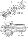
- the embodiment as applied to manufacture of a gear pump-head is shown in FIGS. 1(A) and 1(B) .
- FIG. 1(A) an exploded view of the subject pump-head assembly 10 is shown.
- the pump-head assembly 10 of this embodiment is a magnetically driven gear pump that comprises a first housing portion (end-plate) 12, a second housing portion (cavity-plate) 14, and a magnet cup 16 disposed along an axis A.
- the end-plate 12 includes an inlet port 18 and an outlet port 20.
- the end-plate 12 is configured with gear bushings 22a, 22b into which corresponding gear axles 24a, 24b are journaled. Respective gears 26a, 26b are attached to the gear axles 24a, 24b.
- the gear 26a is the "driven” gear
- the gear 26b is the "driving" gear.
- the gears 26a, 26b interdigitate with each other such that rotation of the driving gear 26b causes contra-rotation of the driven gear 26a.
- the interdigitated gears 26a, 26b are enclosed in a gear cavity 28 defined by an integral "figure-eight" wall 29 of the cavity-plate 14.
- the gear axles 24a, 24b are journaled in respective bushings 30a, 30b mounted in the cavity-plate 14.
- the gear axle 24b extends through the cavity-plate 14 into the magnet cup 16.
- the assembly comprising the end-plate 12, the cavity plate 14, and the enclosed gears 26a, 26b is termed a "gear pump-head.”
- the magnet cup 16 of this embodiment includes a facing surface 36 that is mounted to the rear-facing surface 32 of the cavity-plate 14.
- a static seal 34 is situated between the surfaces 32, 36.
- the magnet cup 16 encloses a magnet 38, which includes an axial keyed opening 40 into which the gear axle 24b is inserted.
- rotation of the magnet 38 about the axis A causes corresponding rotation of the gear axle 24b and hence of the driving gear 26b.
- the magnet cup 16 includes integral alignment pins 42 that are inserted, during assembly, into corresponding holes 44 defined in the rear-facing surface 32 so that the magnet cup aligns accurately with the cavity-plate 14.
- the magnet 38 of this embodiment is bathed with the fluid being pumped by the pump-head assembly 10 as the fluid circulates inside the magnet cup 16.
- the end-plate 12 of this embodiment defines a "figure-eight" raised face 46 that slip-fits into the gear cavity 38 during assembly ( FIG. 1(B) ), which serves to align the plates 12, 14 with each other.
- the magnet 38 includes an axle portion 48 journaled in a bushing 50 in the bottom of the magnet cup 16.
- the magnet cup 16 and housing portions 12, 14 can be fastened together using screws, clips, or other mechanical fasteners (not shown) that extend through mounting holes 52.
- the magnet cup 16 can be fastened to the housing portion 14 using mechanical fasteners, while the housing portions 12, 14 are bonded together (see below).
- all three components 12, 14, 16 can be bonded together. Further alternatively, these components can be both bonded together and fastened together.
- the bushings 22a, 22b, 30a, 30b are shown in FIGS. 1(A) and 1(B) as separate parts that are mounted to the plates 12, 14, respectively, but made of a different material than the plates 12, 14.
- the bushings can be integral with, and/or made of the same material as, the respective plates.
- exemplary materials are: fiber-reinforced polyetherimide for the plates 12, 14 and magnet cup 16; thermoplastic polyimide for the gears 26a, 26b and bushings 22a, 22b, 30a, 30b; and yttria-stabilized zirconia for the axles 24a, 24b.
- thin spacers 54a, 54b are situated on the face of each gear 26a, 26b, respectively ( FIG. 1(A) ).
- the spacers 54a, 54b are used to establish a desired end-clearance between the gears 26a, 26b.
- the spacers 54a, 54b are film-like and have a defined thickness (e.g., 20 microns) corresponding to the magnitude of desired end-clearance.
- the respective thicknesses of the spacers 54a, 54b need not be identical, depending upon the desired end-clearance to be established.
- the spacers 54a, 54b are made of a material (e.g.
- the spacers 54a, 54b are shown as separate units but alternatively can be a single unit, especially if their respective thicknesses are identical.
- the gear axles 24a, 24b are then inserted into the bushings 30a, 30b, the gears 26a, 26b are inserted into the gear cavity 28, and the gear axles 24a, 24b are inserted into the bushings 22a, 22b.
- the magnet cup 16 is not yet assembled to the housing, but the housing portions 12, 14 are attached together by bonding (see below), by using one or more mechanical fasteners such as screws, clips, or the like (see above), or by using a combination of these techniques.
- the inlet 18 and outlet 20 desirably are temporarily plugged using a material that does not adhere to the adhesive or other bonding agent used (e.g., Teflon plugs for use with an epoxy adhesive. Temporary plugging prevents the inlet 18 and outlet 20 from becoming occluded by adhesive, material flow, creep, or other such consequence of bonding.
- the adhesive e.g. , epoxy adhesive
- the adhesive is applied in the zone 56 ( FIG. 1(A) ) between the wall 29 and end-plate 12.
- the raised face 46 is inserted into the gear cavity 28, and the plates 12, 14 are urged toward each other (usually with a specified force, called "preload") until the raised face comes in contact with the films 54a, 54b.
- the adhesive is cured at an appropriate curing temperature for the particular adhesive (e.g., 195°C) for a suitable time (e.g., 13 minutes).
- the solvent is circulated through the pump-head (while rotating the gears) to dissolve the spacers 54a, 54b, to produce the desired end-clearance between the gears 26a, 26b and the housing portions 12, 14 in the gear cavity 28. Afterward, the inlet and outlet are unplugged.
- the housing portions 12, 14 can be bonded together after they, as a result of application of preload, are actually in contact with each other. Alternatively, especially if adhesive is used for bonding, sufficient adhesive can be applied to fill space between the housing portions 12, 14 left after applying the preload.
- the magnet 38 and magnet cup 16 are assembled to the pump-head.
- the adhesive used for bonding the plates 12, 14 together assumes whatever thickness (in the axial direction) to take up tolerances in the zone 56 between the wall 29 and the end-plate 12, while the films 54a, 54b provide the desired end-clearance for the gears 26a, 26b relative to the plates 12, 14.
- the housing portions plates 12, 14 are made of metal such as brass or stainless steel. After assembling the gears 26a, 26b in the gear cavity 28, the housing portions 12, 14 are bonded together using a bonding technique suitable for metal, such as brazing or soldering, use of mechanical fasteners, or a combination of these techniques.
- the plates 12, 14 are made of a thermally bondable material such as, but not limited to, any of various plastics.
- a thermal-bonding technique such as heat-and-press, sonic welding, or the like.
- Thermal bonding can be combined or augmented with adhesive bonding, such as using local application of heat to achieve curing of the adhesive and/or to achieve bonding together of the plates.
- the particular configurations of the housing portions 12, 14 described above are not intended to be limiting.
- the housing can be defined using any of various combinations and configurations of housing portions, so long as they allow the gears (or other rotary member(s)), bushings, and other parts to be assembled inside the cavity 28. This usually requires that the housing comprise multiple portions that are assembled together after inserting the rotary member(s).
- the housing portions 12, 14 can be substantially the same size and shape (but be mirror images of each other).
- the magnet 38 being a rotary member situated inside the cavity in which pumped fluid circulates, could also be provided with a spacer to establish a desired end-clearance of the magnet 38 inside the magnet cup 16.
- a spacer would be analogous to a spacer 54a, 54b described above for the gears.
- FIGS. 2(A)-2(B) are similar in certain respects to the first embodiment except that they do not show the soluble spacers 54a, 54b to establish desired end-clearance.
- the rotary members are assembled in the pump-cavity, and the housing portions are assembled while pressing them together axially, followed by running the rotary members, such as under pressure, to remove high-spot interferences and achieve a desired end-clearance.
- FIGS. 2(A) and 2(B) items that are the same as corresponding items shown in FIGS. 1(A) and 1(B) have the same respective reference numerals and are not described further.
- the housing portions (end-plate 112 and cavity-plate 114) in the second embodiment are slightly different than in the first embodiment and thus have different reference numerals than in the first embodiment.
- the gear axles 24a, 24b are inserted into the bushings 30a, 30b, the gears 26a, 26b are inserted into the gear cavity 28, and the gear axles 24a, 24b are inserted into the bushings 22a, 22b to form a pump-head.
- the magnet cup 16 is not attached yet.
- the inlet 18 and outlet 20 are temporarily plugged, and an adhesive 58 (e.g., epoxy adhesive) is applied in the zone 56 ( FIG. 1(A) ) between the wall 29 and end-plate 12. Details are shown in FIG. 2(C) , which shows the end-plate 112 and the cavity-plate 114.
- the cavity-plate 114 defines the cavity wall 129, and the end-plate 112 defines a "figure-eight" raised portion 131 (see “raised face” 46 in FIG. 2(B) ) that, during assembly of the plates 112, 114, is inserted into the gear cavity 28.
- a glue zone 133 Surrounding the raised portion 131 is a glue zone 133 to which the adhesive 58 is applied.
- the raised portion 131 includes a "top" surface 135.
- the plates 112, 114 are urged toward each other until the top surface 135 of the raised portion 131 contacts the opposing surfaces 137 of the gears 26a, 26b (see FIG. 2(D) ).
- the resulting pump-head is placed in a press or the like and subjected to an axial compression load (called "preload,” e.g., 40 pounds) for a suitable time (e.g., 5 seconds) to seat the components together.
- preload e.g. 40 pounds
- a suitable time e.g., 5 seconds
- the adhesive 58 is cured by exposure to a suitable curing temperature (e.g., 195°C) for a suitable time (e.g., 13 minutes).
- the pump-head is placed in a run-in device comprising a specified orifice for producing a desired back pressure in the pump-head (e.g., 40 psi back pressure) during run-in.
- a drive mechanism is coupled to the gear axle 24b protruding from the cavity-plate 114 and actuated to rotate the driving gear 26a for a suitable time (e.g., 1 minute).
- the resulting contra-rotation of the gears 26a, 26b against the side surfaces of the plates 112, 114 removes internal interference between the gears, end-plate 112, and cavity-plate 114, leaving the desired end-clearances inside the pump-cavity 28.
- the magnet cup 16 and magnet 38 are assembled to the pump-head.
- the adhesive 58 assumes whatever thickness (in the axial direction) to occupy the clearance (including tolerance stack-up) in the zone 56 between the wall 129 and the end-plate 112, while the run-in step provides the desired end-clearance for the gears relative to the plates 112, 114.
- gear as used herein encompasses rotary members configured as conventional pump gears as well as any of various other rotary members having lobes, teeth or the like that interdigitate with the same of a second such member to produce, when contra-rotated relative to each other, fluid flow.
- the magnet 38 is driven by a stator 39 or analogous device.
- the stator 39 is placed outside the magnet cup 16 so as to surround the magnet cup (and magnet 38) in a coaxial manner.
- a typical stator comprises wire windings (not detailed) associated with an iron core, wherein the core surrounds the magnet cup.
- the windings are selectively energized by electronics. Power is supplied to the electronics to energize the stator 39 to cause axial rotation of the magnet 38. Rotation of the magnet 38 rotates the driving gear 26b, which contra-rotates the driven gear 26a. This co-rotation of the gears 26a, 26b urges flow of liquid through the pump-cavity 28.
- a soluble spacer for establishing clearance for a rotary or other moving pump member inside a housing is not limited to establishing end-clearance. It is possible that a soluble spacer may be configured and used during manufacture to establish, for example, a desired radial clearance or other clearance than end-clearance.
- FIG. 3 An example circuit 200 is shown in FIG. 3 , which includes a pump 202 having an inlet 204 and an outlet 206.
- the outlet 206 can include a pressure sensor 205.
- the inlet 204 is situated downstream of a filter 208, which is situated downstream of a tank 210 serving as a reservoir for liquid to be pumped by the pump 202.
- the outlet 206 is hydraulically connected to a downstream destination 212 at which pumped liquid is discharged from the circuit or otherwise used.
- the circuit 210 can include a return line 214 for returning liquid to the tank 210 that is not actually discharged at the destination 212.
Landscapes
- Engineering & Computer Science (AREA)
- Mechanical Engineering (AREA)
- General Engineering & Computer Science (AREA)
- Rotary Pumps (AREA)
- Details And Applications Of Rotary Liquid Pumps (AREA)
Description
- This application claims priority to, and the benefit of,
U.S. Provisional Application No. 60/967,214, filed on August 30, 2007 - This application pertains to, inter alia, gear pumps and other pumps having one or more rotary members situated inside a pump housing and used for pumping a fluid in a hydraulic system. Certain embodiments pertain to gear pumps that are magnetically driven and have sealed housings.
- For pumping liquids and other fluids, gear pumps and the like have experienced substantial acceptance in the art due to their comparatively small size, quiet operation, reliability, and cleanliness of operation with respect to the fluid being pumped. Gear pumps also are advantageous for pumping fluids while keeping the fluids isolated from the external environment. This latter benefit has been further enhanced with the advent of magnetically coupled pump-drive mechanisms that have eliminated leak-prone and unreliable shaft seals, i.e., dynamic hydraulic seals around rotating pump-drive shafts.
- Gear pumps have been adapted for use in many applications, including applications requiring extremely accurate delivery of a fluid to a point of use. Such applications include, for example, delivery of liquids in medical and scientific instrumentation. Another application is the delivery of coolant liquids to a location where the coolant liquid can be used for active cooling or temperature control of an object.
- With respect to cooling systems, an emerging application of gear pumps and the like is circulated-liquid cooling of microelectronic devices. Particularly demanding aspects of this application include extremely tight spatial constraints for accommodating a liquid cooling system including a pump, extremely high reliability specifications that must be met, minimal cost, and very low energy budget for running the pump.
- Ongoing efforts in these and other demanding applications have stimulated interest in development of gear pumps that are smaller, more reliable, less expensive, and more energy-efficient. As gear pumps have been miniaturized to meet these criteria, certain technical challenges have arisen.
- One technical challenge pertains to manufacturing the pump-head housing of a light-weight and durable material that is intrinsically low in cost, that can be formed easily and inexpensively, and that holds its dimensions over a long period of time. In this regard, the stainless steel or other metal conventionally used for fabricating larger, conventional pump-head housings has been replaced in many instances with reinforced thermoset plastic. Use of plastic reduces weight substantially and eliminates most if not all the machining steps used in making conventional pump-head housings of metal. The reinforcement (e.g., fibers) provides dimensional and structural stability and durability. Also, compared to metal, plastic is intrinsically lower in cost and advantageously can be molded, which further reduces manufacturing costs.
- In addition to use for making miniature pump-head housings, plastic or other suitable is also being used for making the gear set enclosed within a "gear cavity" or "pump-cavity" in the housing of the gear pump-head. Even very small gears made of plastic exhibit high reliability and durability for certain applications. Also, as in conventional magnetically driven gear pump-heads, plastic is used for fabricating the magnet cup of miniature pump-heads. The magnet cup is a sealable enclosure for an axially rotatable magnet that is mechanically coupled to one of the gears (the "driving gear") and magnetically coupled to a driver (usually configured as a coaxial stator) situated outside the magnet cup. The rotating magnetic field produced by the driver passes through the walls of the magnet cup to the magnet to cause rotation of the magnet. The interior of the magnet cup (including the magnet) is usually bathed by the liquid being pumped by the pump-head, and hence is hydraulically coupled to the gear cavity.
- Another technical challenge pertains to tolerance stack-up. As parts of the pump-head are reduced in size, the dimensional tolerances of each part become tighter and more difficult to achieve and control. Also, the tolerances in individual parts "stack-up" as multiple parts are assembled into a pump-head. For example, dimensional tolerances of individual housing parts and rotary members that can be accommodated in a conventional pump-head are intolerable in a miniature pump-head that is five to ten times smaller. Problems with tolerance stack-up arise no matter how the parts are fabricated, whether by molding or machining, and without regard to the particular material from which the parts are fabricated. Also, costs rise substantially in close-tolerance fabrication processes, including molding.
- Tolerance issues arise in all the dimensions of miniature parts. For example, a pump-head housing normally comprises at least several housing portions that must be very accurately aligned with each other and with other parts (e.g., the gears and magnet cup) during assembly. Conventional alignment aids include use of alignment pins, mechanical fasteners, or the like, especially if permissible from a cost standpoint. But, with substantial miniaturization of the pump-head, alignment pins become too small to be effective and/or usable in many instances (and the need to hold tight tolerances on the pins themselves makes them prohibitively expensive to manufacture). Hence, there are practical limits to the closeness by which tolerances can be held in miniature parts fabricated by conventional methods and to the tolerance stack-ups that inevitably result when the parts are assembled together. These limits (and the costs associated with overcoming them) must be addressed as miniaturization goals continue to be pursued.
- Yet another technical challenge with miniature pump-heads is establishment and maintenance of adequate static seals between housing portions. In conventional larger pump-head housings, O-rings or the like are used to form static seals between mating housing portions. Miniaturization of pump-head housings has required corresponding reductions in the size and thicknesses of O-rings that can be used. This, in turn, raises tolerance problems in molding the O-rings and in forming the glands in which the O-rings are placed for use in forming static seals.
- In miniature pump-heads the clearance of the gears or other rotary members relative to the cavity defined in the housing is also a critical issue. For example, gear clearance relative to the housing is directly related to tolerance stack-ups involving the gears as well as the parts of the housing defining the gear cavity. This clearance issue pertains not only to radial clearance of the gears in the gear cavity but also to axial (end) clearance of the gears relative to end walls of the gear cavity. In miniature pump-heads these clearance windows can be tens of microns or less. Excessive clearance (radially and/or axially) can cause the pump-head to exhibit excessive back-flow. "Negative" clearance (i.e.. no clearance at all) can result in the gears being bound-up in the housing, which renders the pump-head inoperable. Thus, the difference between too much clearance and insufficient (or even negative) clearance can be extremely small and difficult to control by conventional methods. Since no two identical parts have exactly the same dimensions, due to manufacturing tolerances, and since every component part of a pump-head has its own tolerances, the tolerance stack-up from one pump-head to the next on a manufacturing line can make achieving the right clearance every time nearly impossible when using conventional methods to fabricate miniature pump-heads.
-
JP 7 259 775 -
US 2007/071616 describes segmented assemblies for pumps using a cage to hold magnet segments relative to each other. -
US 6,250,900 describes a hydraulic unit using a layer of abradable coating material to provide side clearance for a rotary element. -
US 2002/0006346 describes a hydraulic device using a film on engaging surfaces of gears to prevent burning and wearing. -
US 4,490,102 describes a compressor in which the inner surfaces of the housing and the outer surfaces of the rotor threads are coated with an over thickened layer of erodible coating material containing particles of a dry lubricant material. - In view of the foregoing, this disclosure provides a method for manufacturing a pump-head including a housing enclosing at least one rotary member.
- The invention provides a method for manufacturing a pump-head including a housing enclosing at least one rotary member, the method comprising: providing a first housing portion and a second housing portion that collectively, when assembled together, define a pump-cavity that accommodates the at least one rotary member; assembling the at least one rotary member into the housing portions; placing a spacer of a defined thickness, corresponding to a desired clearance, in contact with a surface of the at least one rotary member facing a corresponding surface of at least one of the housing portions; the spacer being made of a material that is soluble in a solvent; attaching the first and second housing portions together to form the pump-cavity containing the at least one rotary member; and circulating the solvent in the pump-cavity to dissolve the spacer to provide the desired clearance of the at least one rotary member in the pump-cavity.
- An embodiment of such a method includes steps summarized as follows: First and second housing portions are provided that collectively, when assembled together, define a pump-cavity that accommodates the rotary member(s). The rotary member(s) is assembled into the housing portions so as to be situated in and rotatable within the pump-cavity. Also placed in the pump-cavity is at least one soluble spacer of a defined thickness that corresponds to a desired clearance of a rotary member relative to the pump-cavity. The spacer is placed in contact with a surface of the rotary member facing a corresponding surface of at least one of the housing portions. The first and second housing portions are then attached together to form the pump-cavity containing the rotary member(s). Then, the soluble spacer is dissolved to provide the desired clearance of the rotary member in the pump-cavity. As the housing portions are attached together, e.g., by bonding such as adhesive bonding, the spacer establishes the desired clearance of the rotary member(s) in the pump-cavity. By way of example, the spacer can be made of a material that is water-soluble.
- The housing portions need not be identical in shape or size. At least two portions are typically used so that, when not yet attached together, they define locations at which to place the at least one rotary member and any additional components (e.g., bushings and/or axles). When the portions are subsequently attached together, they define the pump-cavity containing the at least one rotary member and the additional components.
- A key application of the subject method is to the production of gear pump-heads, in which the rotary members are respective gears. However, the methods are not limited to production of gear pump-heads. For example, the at least one rotary member comprises two pump gears, namely a driving gear interdigitated (meshed) with a driven gear. With such pump-heads, the assembling step comprises mounting the pump gears in the pump-cavity before attaching the first and second housing portions together. With pump gears, the desired clearance typically (but not exclusively) is a desired end-clearance of the gears relative to corresponding locations on an inside surface of the pump-cavity. End-clearance can be established by configuring the spacers as soluble washers that are placed coaxially with respective gears to establish the desired end-clearance between the sides of the gears and the corresponding inside surfaces of the pump-cavity.
- As the housing portions are urged toward each other, they can be subjected to a predetermined preload (force with which they are urged together). A specified preload helps ensure that the spacer(s) are seated between the respective rotary member(s) and the corresponding surface(s) of the pump-cavity. So long as the spacers are manufactured to a specified thickness, proper seating of them ensures the desired clearance (corresponding to the thickness) after the spacer(s) are dissolved. Preload is typically applied, if at all, at least during execution of the technique used for attaching the housing portions together. For example, if the housing portions are attached together using an adhesive, preload desirably is applied at least after application of the adhesive and can be continued during curing of the adhesive.
- Attaching the housing portions together can be performed using any of several techniques not limited to adhesive bonding. By way of example, and not intending to be limiting, these alternative techniques include heat-bonding, sonic welding, use of mechanical fasteners, etc. These techniques (as well as the adhesive technique) are especially useful if the housing portions are made of a plastic material, but the techniques can also be used with metal housings. If the housing portions are made of metal, then other techniques alternatively can be used such as, but not limited to, soldering or brazing. The housing portions desirably have sufficient rigidity, and the attachment technique desirably is sufficiently stable, to ensure that the predetermined clearance established by the spacer(s) remains appropriately constant after the spacer(s) have been dissolved away.
- The method can further comprise mounting a rotation device to the pump-head such that the rotation device is coupled to the at least one rotary member. The rotation device typically is energizable in a manner that causes rotation of the rotary member(s) in the pump-cavity. By way of example, the rotation device can comprise a rotatable magnet, that is coupled to at least one rotary member, and a magnet driver magnetically coupled to the rotatable magnet. In such an event, the assembling step can include enclosing the magnet in a magnet cup and mounting the magnetic cup to at least one of the housing portions such that the magnet cup is in hydraulic communication with the pump-cavity.
- The spacer(s) are dissolved by circulating the solvent in the assembled pump-head. A particularly convenient solvent is water, which requires that the spacers be made of a water-soluble material. Meanwhile, the rotary member(s) can be rotated to facilitate dissolution of the spacer(s).
- To attach the housing portions together, adhesive can be used. In such an event, the method can include the steps of applying adhesive to mating surfaces of the first and second housing portions, and curing the adhesive after attaching the first and second housing portions together.
- The method can further comprise the step of mounting a rotatable magnet to the driving gear, and enclosing the magnet in a magnet cup mounted to at least one of the housing portions and in fluid communication with the gear-cavity.
- The first and second housing portions may be attached together to form the pump-cavity containing the rotary member(s) such that each rotary member contacts a corresponding surface of the pump-cavity. The rotary member(s) in the pump-cavity may be actuated (rotated) to reduce an internal interference between the rotary member(s) and the corresponding surface(s) of the pump-cavity. By causing motion of the rotary member(s) relative to the surface(s) of the pump-cavity, high-points and other microscopic irregularities in the surfaces of the rotary member(s) and pump-cavity surfaces may be eroded and smoothed out, thereby establishing a very close-tolerance clearance between the rotary member(s) and pump-cavity surfaces on a consistent basis from one pump-head to the next on an assembly line.
- As noted above, the rotary member(s) can be a driving gear enmeshed with at least one driven gear. In such an event, the actuating step reduces an internal interference between the gears and respective surfaces of the housing portions, to provide desired respective end-clearances of the gears inside the pump-cavity.
- The attaching step desirably comprises urging the first and second housing portions toward each other until stopped by contact of the housing portions against respective facing surfaces of the gears. This urging desirably is at a specified preload. The housing portions are bonded or otherwise connected together, wherein the preload desirably is applied at least during a portion of the time that the bonding or the like is being performed.
- This method embodiment can be combined with the first embodiment summarized above, in which during the assembling step, a soluble spacer is placed between the rotary member and a corresponding surface of the pump-cavity. After the attaching step, the spacer is dissolved.
- The foregoing and other objects, features, and advantages of the invention will become more apparent from the following detailed description, which proceeds with reference to the accompanying figures.
-
-
FIG. 1(A) is a perspective, axially exploded view of a gear pump-head according to the first representative embodiment. -
FIG. 1(B) is an elevational section (along the median sagittal plane) of the assembled gear pump-head of the first representative embodiment. -
FIG. 2(A) is a perspective, axially exploded view of a gear pump-head according to the second representative embodiment. -
FIG. 2(B) is an elevational section (along the median sagittal plane) of the assembled gear pump-head of the second first representative embodiment. -
FIG. 2(C) is a perspective view of two housing portions placed in position for assembly, according to the second representative embodiment. -
FIG. 2(D) is an elevational section (along the median sagittal plane) of the assembled housing of the second representative embodiment. -
FIG. 3 is a schematic diagram of an exemplary hydraulic circuit with which a pump-head as described herein can be used. - This invention addresses and solves the problems articulated above, especially with respect to miniature gear pump-heads and other pump-heads including one or more rotary members. Namely, inter alia, methods are provided that solve these problems.
- This disclosure is set forth in the context of representative embodiments that are not intended to be limiting in any way.
- As used herein, the singular forms "a," "an," and "the" include the plural forms unless the context clearly dictates otherwise. Additionally, the term "includes" means "comprises." Further, the term "coupled" encompasses mechanical as well as other practical ways of coupling or linking items together, and does not exclude the presence of intermediate elements between the coupled items.
- The described things and methods described herein should not be construed as being limiting in any way. Instead, this disclosure is directed toward all novel and non-obvious features and aspects of the various disclosed embodiments, alone and in various combinations and sub-combinations with one another. The disclosed things and methods are not limited to any specific aspect or feature or combinations thereof, nor do the disclosed things and methods require that any one or more specific advantages be present or problems be solved.
- Although the operations of some of the disclosed methods are described in a particular, sequential order for convenient presentation, it should be understood that this manner of description encompasses rearrangement, unless a particular ordering is required by specific language set forth below. For example, operations described sequentially may in some cases be rearranged or performed concurrently. Moreover, for the sake of simplicity, the attached figures may not show the various ways in which the disclosed things and methods can be used in conjunction with other things and method. Additionally, the description sometimes uses terms like "produce" and "provide" to describe the disclosed methods. These terms are high-level abstractions of the actual operations that are performed. The actual operations that correspond to these terms will vary depending on the particular implementation and are readily discernible by one of ordinary skill in the art.
- In the following description, certain terms may be used such as "up," "down,", "upper," "lower," "horizontal," "vertical," "left," "right," and the like. These terms are used, where applicable, to provide some clarity of description when dealing with relative relationships. But, these terms are not intended to imply absolute relationships, positions, and/or orientations. For example, with respect to an object, an "upper" surface can become a "lower" surface simply by turning the object over. Nevertheless, it is still the same object.
- Various embodiments of the methods have one or more of the following characteristics: (a) substantial elimination of mechanical fasteners, such as screws or the like, as well as substantial elimination of separate alignment pins to reduce parts count and hence cost; (b) incorporation of one or more alignment features into certain parts to achieve accuracy of part-to-part alignment without having to use separate alignment features or components; (c) to achieve a desired end-clearance of a rotary member(s) in its housing, a thin, soluble, temporary spacer is placed between the rotary member and an inside surface of the housing during assembly, and the spacer is subsequently dissolved to establish the desired clearance between the rotary member(s) and the housings; (d) to achieve a desired end-clearance of the rotary member(s) in the housing, the rotary member(s) is assembled in the pump-cavity, and the housing portions are assembled while pressing them together axially, followed by running the rotary member(s) under pressure to remove high-spot interferences between the rotary member(s) and an inside surface of the housing, to establish a desired end-clearance; and (e) to achieve part-to-part fastening and liquid sealing, the mating portions of the housing are bonded together using a suitable adhesive or other bonding technique appropriate for the material of which the housing is made. The subject methods are particularly suitable for high-volume production of miniaturized pump-heads while achieving desired levels of reliability and durability of miniaturized, hermetically sealed, magnetically driven pumps.
- Various embodiments are described in the context of gear pump-heads in which the rotary members (usually at least two per housing) are interdigitated gears that rotate about parallel axes. But, it will be understood that the principles described herein are also applicable to pump-heads in which other types of rotary members are used such as centrifugal rotors, lobed rotors, rotary pistons, etc., are used.
- Various embodiments are described in the context of at least the housing being made of a suitable plastic material. However, it will be understood that the principles described herein are also applicable to housings being made of any of various other materials such as, but not limited to ceramic, metal, semiconductor, glassy material, etc.
- The first embodiment is directed to a method for manufacturing a pump-head, in which a desired end-clearance of the rotary member(s) in the housing is achieved during manufacture. The embodiment as applied to manufacture of a gear pump-head is shown in
FIGS. 1(A) and 1(B) . Turning first toFIG. 1(A) , an exploded view of the subject pump-head assembly 10 is shown. The pump-head assembly 10 of this embodiment is a magnetically driven gear pump that comprises a first housing portion (end-plate) 12, a second housing portion (cavity-plate) 14, and amagnet cup 16 disposed along an axis A. The end-plate 12 includes aninlet port 18 and anoutlet port 20. The end-plate 12 is configured withgear bushings gear axles Respective gears gear axles gear 26a is the "driven" gear, and thegear 26b is the "driving" gear. Thegears driving gear 26b causes contra-rotation of the drivengear 26a. The interdigitated gears 26a, 26b are enclosed in agear cavity 28 defined by an integral "figure-eight"wall 29 of the cavity-plate 14. Thegear axles respective bushings plate 14. Thegear axle 24b extends through the cavity-plate 14 into themagnet cup 16. The assembly comprising the end-plate 12, thecavity plate 14, and theenclosed gears - The
magnet cup 16 of this embodiment includes a facingsurface 36 that is mounted to the rear-facingsurface 32 of the cavity-plate 14. Astatic seal 34 is situated between thesurfaces magnet cup 16 encloses amagnet 38, which includes an axial keyedopening 40 into which thegear axle 24b is inserted. Thus, rotation of themagnet 38 about the axis A causes corresponding rotation of thegear axle 24b and hence of thedriving gear 26b. Themagnet cup 16 includes integral alignment pins 42 that are inserted, during assembly, into correspondingholes 44 defined in the rear-facingsurface 32 so that the magnet cup aligns accurately with the cavity-plate 14. Themagnet 38 of this embodiment is bathed with the fluid being pumped by the pump-head assembly 10 as the fluid circulates inside themagnet cup 16. - The end-
plate 12 of this embodiment defines a "figure-eight" raisedface 46 that slip-fits into thegear cavity 38 during assembly (FIG. 1(B) ), which serves to align theplates magnet 38 includes anaxle portion 48 journaled in abushing 50 in the bottom of themagnet cup 16. Themagnet cup 16 andhousing portions holes 52. Alternatively, themagnet cup 16 can be fastened to thehousing portion 14 using mechanical fasteners, while thehousing portions components - The
bushings FIGS. 1(A) and 1(B) as separate parts that are mounted to theplates plates - Without intending to be limiting in any way, exemplary materials are: fiber-reinforced polyetherimide for the
plates magnet cup 16; thermoplastic polyimide for thegears bushings axles - During assembly of a gear pump-head using a method according to this embodiment,
thin spacers gear FIG. 1(A) ). Thespacers gears spacers spacers spacers spacers gear axles bushings gears gear cavity 28, and thegear axles bushings magnet cup 16 is not yet assembled to the housing, but thehousing portions - If the
housing portions inlet 18 andoutlet 20 desirably are temporarily plugged using a material that does not adhere to the adhesive or other bonding agent used (e.g., Teflon plugs for use with an epoxy adhesive. Temporary plugging prevents theinlet 18 andoutlet 20 from becoming occluded by adhesive, material flow, creep, or other such consequence of bonding. If an adhesive is used for bonding, the adhesive (e.g., epoxy adhesive) is applied in the zone 56 (FIG. 1(A) ) between thewall 29 and end-plate 12. The raisedface 46 is inserted into thegear cavity 28, and theplates films spacers gears housing portions gear cavity 28. Afterward, the inlet and outlet are unplugged. - The
housing portions housing portions - After assembling the housing portions as described above, the
magnet 38 andmagnet cup 16 are assembled to the pump-head. In the finished pump-head assembly 10, the adhesive used for bonding theplates zone 56 between thewall 29 and the end-plate 12, while thefilms gears plates - In an alternative configuration, the
housing portions plates gears gear cavity 28, thehousing portions - In another alternative configuration, the
plates gears gear cavity 28, theplates - The particular configurations of the
housing portions cavity 28. This usually requires that the housing comprise multiple portions that are assembled together after inserting the rotary member(s). For example, thehousing portions - It is also realized that the
magnet 38, being a rotary member situated inside the cavity in which pumped fluid circulates, could also be provided with a spacer to establish a desired end-clearance of themagnet 38 inside themagnet cup 16. Such a spacer would be analogous to aspacer -
FIGS. 2(A)-2(B) are similar in certain respects to the first embodiment except that they do not show thesoluble spacers - In
FIGS. 2(A) and 2(B) , items that are the same as corresponding items shown inFIGS. 1(A) and 1(B) have the same respective reference numerals and are not described further. The housing portions (end-plate 112 and cavity-plate 114) in the second embodiment are slightly different than in the first embodiment and thus have different reference numerals than in the first embodiment. - To manufacture a pump-
head assembly 100 using a method according to the second embodiment, thegear axles bushings gears gear cavity 28, and thegear axles bushings magnet cup 16 is not attached yet.) Theinlet 18 andoutlet 20 are temporarily plugged, and an adhesive 58 (e.g., epoxy adhesive) is applied in the zone 56 (FIG. 1(A) ) between thewall 29 and end-plate 12. Details are shown inFIG. 2(C) , which shows the end-plate 112 and the cavity-plate 114. The cavity-plate 114 defines thecavity wall 129, and the end-plate 112 defines a "figure-eight" raised portion 131 (see "raised face" 46 inFIG. 2(B) ) that, during assembly of theplates gear cavity 28. Surrounding the raisedportion 131 is aglue zone 133 to which the adhesive 58 is applied. The raisedportion 131 includes a "top"surface 135. - After inserting the raised portion 131 (raised face 46) into the
gear cavity 28, theplates top surface 135 of the raisedportion 131 contacts the opposingsurfaces 137 of thegears FIG. 2(D) ). The resulting pump-head is placed in a press or the like and subjected to an axial compression load (called "preload," e.g., 40 pounds) for a suitable time (e.g., 5 seconds) to seat the components together. The adhesive 58 is cured by exposure to a suitable curing temperature (e.g., 195°C) for a suitable time (e.g., 13 minutes). After fully curing the adhesive 58, the pump-head is placed in a run-in device comprising a specified orifice for producing a desired back pressure in the pump-head (e.g., 40 psi back pressure) during run-in. A drive mechanism is coupled to thegear axle 24b protruding from the cavity-plate 114 and actuated to rotate thedriving gear 26a for a suitable time (e.g., 1 minute). The resulting contra-rotation of thegears plates plate 112, and cavity-plate 114, leaving the desired end-clearances inside the pump-cavity 28. After run-in, themagnet cup 16 andmagnet 38 are assembled to the pump-head. - Thus, in the finished pump-
head assembly 100, the adhesive 58 assumes whatever thickness (in the axial direction) to occupy the clearance (including tolerance stack-up) in thezone 56 between thewall 129 and the end-plate 112, while the run-in step provides the desired end-clearance for the gears relative to theplates - It will be understood that "gear" as used herein encompasses rotary members configured as conventional pump gears as well as any of various other rotary members having lobes, teeth or the like that interdigitate with the same of a second such member to produce, when contra-rotated relative to each other, fluid flow.
- The
magnet 38 is driven by astator 39 or analogous device. Thestator 39 is placed outside themagnet cup 16 so as to surround the magnet cup (and magnet 38) in a coaxial manner. A typical stator comprises wire windings (not detailed) associated with an iron core, wherein the core surrounds the magnet cup. The windings are selectively energized by electronics. Power is supplied to the electronics to energize thestator 39 to cause axial rotation of themagnet 38. Rotation of themagnet 38 rotates thedriving gear 26b, which contra-rotates the drivengear 26a. This co-rotation of thegears cavity 28. - These methods may be utilized in the manufacture of an offset-drive, magnetically driven, gear pump-head as discussed in
U.S. Patent No. 7,267,532 to Krebs , especially columns 7-13 andFIGS. 1-6 of that patent. - It will be appreciated that principles described above in connection with these embodiments are advantageously applied to miniature pump-heads, but are not limited to such pump-heads. Establishing a specified end-clearance on a consistent basis in manufacturing pump-heads is an important objective, even with pump-heads that are larger than "miniature." "Miniature" pump-heads are generally 1 in3 (16387 mm3) or less in volume.
- It will also be understood that use of a soluble spacer for establishing clearance for a rotary or other moving pump member inside a housing is not limited to establishing end-clearance. It is possible that a soluble spacer may be configured and used during manufacture to establish, for example, a desired radial clearance or other clearance than end-clearance.
- It will be understood that a pump-head manufactured by methods such as the embodiments described above can be connected to and used with any of various types of hydraulic circuits. An
example circuit 200 is shown inFIG. 3 , which includes apump 202 having aninlet 204 and anoutlet 206. Theoutlet 206 can include a pressure sensor 205. Theinlet 204 is situated downstream of afilter 208, which is situated downstream of atank 210 serving as a reservoir for liquid to be pumped by thepump 202. Theoutlet 206 is hydraulically connected to adownstream destination 212 at which pumped liquid is discharged from the circuit or otherwise used. If desired, thecircuit 210 can include areturn line 214 for returning liquid to thetank 210 that is not actually discharged at thedestination 212. - In view of the many possible embodiments to which the principles of the disclosed invention may be applied, it should be recognized that the illustrated embodiments are only preferred examples of the invention and should not be taken as limiting the scope of the invention. Rather, the scope of the invention is defined by the following claims.
Claims (12)
- A method for manufacturing a pump-head (10) including a housing enclosing at least one rotary member, the method comprising:providing a first housing portion (12) and a second housing portion (14) that collectively, when assembled together, define a pump-cavity (28) that accommodates the at least one rotary member:assembling the at least one rotary member into the housing portions;placing a soluble spacer (54a; 54b) of a defined thickness, corresponding to a desired clearance, in contact with a surface of the at least one rotary member facing a corresponding surface of at least one of the housing portions (12, 14), the spacer being made of a material that is soluble in a solvent;attaching the first (12) and second (14) housing portions together to form the pump-cavity (28) containing the at least one rotary member; andcirculating the solvent in the pump-cavity to dissolve the spacer (54a; 54b) to provide the desired clearance of the at least one rotary member in the pump-cavity (28).
- The method of claim 1, wherein the attaching step comprises urging the first (12) and second (14) housing portions toward each other to establish a specified preload to the housing until stopped by the soluble spacer (54a, 54b).
- The method of claim 1, wherein:the at least one rotary member comprises multiple pump gears (26a, 26b); andthe assembling step comprises mounting the pump gears (26a, 26b) in the pump-cavity (28) before attaching the first (12) and second (14) housing portions together.
- The method of claim 1, wherein the desired clearance is a desired end-clearance of the at least one rotary member relative to a corresponding location on an inside surface of the pump-cavity (28).
- The method of claim 1, wherein:the at least one rotary member comprises first and second gears (26a, 26b) intermeshed with each other in the pump-cavity (28); andthe desired clearance is a desired end-clearance of the gears (26a, 26b) relative to corresponding locations on an inside surface of the pump-cavity (28).
- The method of claim 5, wherein placing the soluble spacer (54a, 54b) comprises placing a soluble washer coaxially with a respective gear to establish the desired end-clearance between a side of the gear and the corresponding inside surface of the pump-cavity (28).
- The method of claim 1, wherein the attaching step comprises bonding the first (12) and second (14) housing portions together.
- The method of claim 7, wherein bonding comprises:applying adhesive to mating surfaces of the first (12) and second (14) housing portions; andafter attaching the first (12) and second (14) housing portions together, curing the adhesive.
- The method of claim 8, further comprising applying a preload to the first (12) and second (14) housing portions before curing the adhesive.
- The method of claim 1, further comprising mounting a rotation device to the pump-head (10) such that the rotation device is coupled to the at least one rotary member, the rotation device being energizable in a manner causing rotation of the at least one rotary member in the pump-cavity (28).
- The method of claim 10, wherein:the rotation device comprises a rotatable magnet (38) coupled to at least one rotary member and a magnet driver magnetically coupled to the rotatable magnet; andthe assembling step comprises enclosing the magnet (38) in a magnet cup (16) and mounting the magnetic cup (16) to at least one of the housing portions (12, 14) such that the magnet cup (16) is in hydraulic communication with the pump-cavity (28).
- The method of claim 1, further comprising rotating the at least one rotary member while circulating the solvent.
Applications Claiming Priority (2)
| Application Number | Priority Date | Filing Date | Title |
|---|---|---|---|
| US96721407P | 2007-08-30 | 2007-08-30 | |
| PCT/US2008/074877 WO2009029855A1 (en) | 2007-08-30 | 2008-08-29 | Methods for manufacturing pump-heads having a desired internal clearance for rotary member |
Publications (3)
| Publication Number | Publication Date |
|---|---|
| EP2188526A1 EP2188526A1 (en) | 2010-05-26 |
| EP2188526A4 EP2188526A4 (en) | 2013-04-24 |
| EP2188526B1 true EP2188526B1 (en) | 2016-06-01 |
Family
ID=40387843
Family Applications (1)
| Application Number | Title | Priority Date | Filing Date |
|---|---|---|---|
| EP08799004.0A Active EP2188526B1 (en) | 2007-08-30 | 2008-08-29 | Methods for manufacturing pump-heads having a desired internal clearance for rotary member |
Country Status (5)
| Country | Link |
|---|---|
| US (1) | US8186055B2 (en) |
| EP (1) | EP2188526B1 (en) |
| JP (1) | JP2010538206A (en) |
| CA (1) | CA2698208C (en) |
| WO (1) | WO2009029855A1 (en) |
Families Citing this family (19)
| Publication number | Priority date | Publication date | Assignee | Title |
|---|---|---|---|---|
| ITMI20090188U1 (en) * | 2009-06-08 | 2010-12-09 | Fluid O Tech Srl | CONTAINMENT SET FOR A VOLUMETRIC PUMP |
| US8866347B2 (en) | 2010-01-15 | 2014-10-21 | Idex Asa | Biometric image sensing |
| US8791792B2 (en) | 2010-01-15 | 2014-07-29 | Idex Asa | Electronic imager using an impedance sensor grid array mounted on or about a switch and method of making |
| US8421890B2 (en) | 2010-01-15 | 2013-04-16 | Picofield Technologies, Inc. | Electronic imager using an impedance sensor grid array and method of making |
| US8568502B2 (en) | 2010-08-30 | 2013-10-29 | Ford Global Technologies, Llc | Spring clamp for an air filter housing |
| US8876498B2 (en) * | 2010-11-22 | 2014-11-04 | Micropump, Inc. | Pumps and pump-heads with separately removable field-serviceable portion |
| WO2013155224A1 (en) | 2012-04-10 | 2013-10-17 | Picofield Technologies Inc. | Biometric sensing |
| KR101505450B1 (en) * | 2014-01-17 | 2015-03-25 | 이지훈 | Gear pump for supply of thermosetting uv resin |
| DE102015002352A1 (en) * | 2014-12-17 | 2016-06-23 | Brose Fahrzeugteile GmbH & Co. Kommanditgesellschaft, Würzburg | Electric oil pump, in particular for a motor vehicle |
| US11124093B2 (en) | 2018-08-08 | 2021-09-21 | Fisher & Company, Incorporated | Recliner mechanism for seat assembly and method of manufacturing |
| US11260777B2 (en) | 2018-08-29 | 2022-03-01 | Fisher & Company, Incorporated | Recliner heart for seat recliner assembly |
| US11364577B2 (en) * | 2019-02-11 | 2022-06-21 | Fisher & Company, Incorporated | Recliner mechanism for seat assembly and method of manufacturing |
| US11845367B2 (en) | 2019-04-18 | 2023-12-19 | Fisher & Company, Incorporated | Recliner heart having lubricant member |
| US11052797B2 (en) | 2019-08-09 | 2021-07-06 | Fisher & Company, Incorporated | Recliner heart for seat assembly |
| US11192473B2 (en) | 2019-08-30 | 2021-12-07 | Fisher & Company, Incorporated | Release handle for recliner mechanism of vehicle seat |
| US11607976B2 (en) | 2020-03-06 | 2023-03-21 | Fisher & Company, Incorporated | Recliner mechanism having bracket |
| US11766957B2 (en) | 2021-02-16 | 2023-09-26 | Fisher & Company, Incorporated | Release mechanism for seat recliner assembly |
| US11897372B2 (en) | 2021-05-06 | 2024-02-13 | Fisher & Company, Incorporated | Recliner heart having biasing members |
| US11850975B2 (en) | 2021-06-11 | 2023-12-26 | Fisher & Company, Incorporated | Vehicle seat recliner mechanism with welded spring |
Family Cites Families (9)
| Publication number | Priority date | Publication date | Assignee | Title |
|---|---|---|---|---|
| JPS54122646A (en) | 1978-03-16 | 1979-09-22 | Toshiba Corp | Welding method for pipe inserted into hole |
| US4370110A (en) | 1979-07-06 | 1983-01-25 | Fluid Energy Systems Corporation | High pressure gear pump or motor with axial retaining means in a housing cavity |
| FR2530742B1 (en) * | 1982-07-22 | 1987-06-26 | Dba | VOLUMETRIC SCREW COMPRESSOR |
| US4674772A (en) * | 1985-04-25 | 1987-06-23 | Lycan Goodwin A | Soluble pipe spacer |
| JP3373286B2 (en) * | 1994-03-17 | 2003-02-04 | 栃木富士産業株式会社 | compressor |
| US6250900B1 (en) * | 1999-11-15 | 2001-06-26 | Sauer-Danfoss Inc. | Positive displacement hydraulic unit with near-zero side clearance |
| JP2002020780A (en) * | 2000-07-07 | 2002-01-23 | Komatsu Ltd | Water-based working fluid and hydraulic equipment |
| US7267532B2 (en) | 2004-12-28 | 2007-09-11 | Micropump, Inc., A Unit Of Idex Corporation | Offset-drive magnetically driven gear-pump heads and gear pumps comprising same |
| US20070071616A1 (en) | 2005-09-27 | 2007-03-29 | Micropump, Inc., A Unit Of Idex Corporation | Segmented driven-magnet assemblies for pumps, and pumps comprising same |
-
2008
- 2008-08-29 US US12/201,842 patent/US8186055B2/en active Active
- 2008-08-29 CA CA2698208A patent/CA2698208C/en active Active
- 2008-08-29 JP JP2010523169A patent/JP2010538206A/en active Pending
- 2008-08-29 EP EP08799004.0A patent/EP2188526B1/en active Active
- 2008-08-29 WO PCT/US2008/074877 patent/WO2009029855A1/en not_active Ceased
Non-Patent Citations (1)
| Title |
|---|
| ANONYMOUS: "dissolve - definition of dissolve by the Free Online Dictionary, Thesaurus and Encyclopedia.", 6 March 2014 (2014-03-06), XP055105876, Retrieved from the Internet <URL:http://www.thefreedictionary.com/dissolve> [retrieved on 20140306] * |
Also Published As
| Publication number | Publication date |
|---|---|
| CA2698208A1 (en) | 2009-03-05 |
| EP2188526A4 (en) | 2013-04-24 |
| JP2010538206A (en) | 2010-12-09 |
| US20090056124A1 (en) | 2009-03-05 |
| WO2009029855A1 (en) | 2009-03-05 |
| US8186055B2 (en) | 2012-05-29 |
| CA2698208C (en) | 2016-06-07 |
| EP2188526A1 (en) | 2010-05-26 |
Similar Documents
| Publication | Publication Date | Title |
|---|---|---|
| US8186055B2 (en) | Methods for manufacturing pump-heads having a desired internal clearance for rotary member | |
| US8734139B2 (en) | Pumps and pump heads comprising volume-compensation feature | |
| KR100865196B1 (en) | Internal gear type pump with built-in motor and electronic device | |
| US9404492B2 (en) | Pump device having a micro pump and bearing member for a micro pump | |
| JP5474117B2 (en) | Electric pump and electric pump manufacturing method | |
| CN111492143B (en) | Gerotor pump and method of manufacturing the same | |
| CN102213208B (en) | Electric device mounted in electric compressor | |
| US20100074777A1 (en) | Arrangement for delivering fluids | |
| CN107923389B (en) | Electric pump and method for manufacturing the same | |
| CN107787409A (en) | Fluid pump | |
| CN114123595B (en) | Pump-motor unit comprising an integrated housing cover | |
| JP2007292005A (en) | Pump device and power steering device | |
| FI101097B (en) | an eccentric | |
| CN116263156A (en) | screw pump | |
| JP4646629B2 (en) | Vane rotary air pump | |
| JP7169516B2 (en) | Gear pump manufacturing method | |
| US20070071616A1 (en) | Segmented driven-magnet assemblies for pumps, and pumps comprising same | |
| EP2273121B1 (en) | Container assembly for a volumetric pump | |
| JP4001056B2 (en) | Electric pump | |
| US20070014677A1 (en) | Pump | |
| JP2009299471A (en) | Gear pump having magnetic coupling mechanism | |
| JP4859425B2 (en) | Pump device and its case assembly method. | |
| GB2559747A (en) | Pump and method of operation | |
| JPH01125583A (en) | Gear type pump | |
| JP2024528315A (en) | Compressor Assembly |
Legal Events
| Date | Code | Title | Description |
|---|---|---|---|
| PUAI | Public reference made under article 153(3) epc to a published international application that has entered the european phase |
Free format text: ORIGINAL CODE: 0009012 |
|
| 17P | Request for examination filed |
Effective date: 20100305 |
|
| AK | Designated contracting states |
Kind code of ref document: A1 Designated state(s): AT BE BG CH CY CZ DE DK EE ES FI FR GB GR HR HU IE IS IT LI LT LU LV MC MT NL NO PL PT RO SE SI SK TR |
|
| AX | Request for extension of the european patent |
Extension state: AL BA MK RS |
|
| DAX | Request for extension of the european patent (deleted) | ||
| REG | Reference to a national code |
Ref country code: DE Ref legal event code: R079 Ref document number: 602008044544 Country of ref document: DE Free format text: PREVIOUS MAIN CLASS: F04B0017000000 Ipc: F04C0002180000 |
|
| A4 | Supplementary search report drawn up and despatched |
Effective date: 20130322 |
|
| RIC1 | Information provided on ipc code assigned before grant |
Ipc: F04C 2/18 20060101AFI20130318BHEP Ipc: F04B 53/22 20060101ALI20130318BHEP |
|
| 17Q | First examination report despatched |
Effective date: 20140312 |
|
| GRAP | Despatch of communication of intention to grant a patent |
Free format text: ORIGINAL CODE: EPIDOSNIGR1 |
|
| INTG | Intention to grant announced |
Effective date: 20151216 |
|
| GRAS | Grant fee paid |
Free format text: ORIGINAL CODE: EPIDOSNIGR3 |
|
| GRAA | (expected) grant |
Free format text: ORIGINAL CODE: 0009210 |
|
| AK | Designated contracting states |
Kind code of ref document: B1 Designated state(s): AT BE BG CH CY CZ DE DK EE ES FI FR GB GR HR HU IE IS IT LI LT LU LV MC MT NL NO PL PT RO SE SI SK TR |
|
| REG | Reference to a national code |
Ref country code: GB Ref legal event code: FG4D |
|
| REG | Reference to a national code |
Ref country code: CH Ref legal event code: EP Ref country code: AT Ref legal event code: REF Ref document number: 804050 Country of ref document: AT Kind code of ref document: T Effective date: 20160615 |
|
| REG | Reference to a national code |
Ref country code: IE Ref legal event code: FG4D |
|
| REG | Reference to a national code |
Ref country code: DE Ref legal event code: R096 Ref document number: 602008044544 Country of ref document: DE |
|
| REG | Reference to a national code |
Ref country code: LT Ref legal event code: MG4D |
|
| REG | Reference to a national code |
Ref country code: NL Ref legal event code: MP Effective date: 20160601 |
|
| PG25 | Lapsed in a contracting state [announced via postgrant information from national office to epo] |
Ref country code: FI Free format text: LAPSE BECAUSE OF FAILURE TO SUBMIT A TRANSLATION OF THE DESCRIPTION OR TO PAY THE FEE WITHIN THE PRESCRIBED TIME-LIMIT Effective date: 20160601 Ref country code: NO Free format text: LAPSE BECAUSE OF FAILURE TO SUBMIT A TRANSLATION OF THE DESCRIPTION OR TO PAY THE FEE WITHIN THE PRESCRIBED TIME-LIMIT Effective date: 20160901 Ref country code: LT Free format text: LAPSE BECAUSE OF FAILURE TO SUBMIT A TRANSLATION OF THE DESCRIPTION OR TO PAY THE FEE WITHIN THE PRESCRIBED TIME-LIMIT Effective date: 20160601 |
|
| REG | Reference to a national code |
Ref country code: AT Ref legal event code: MK05 Ref document number: 804050 Country of ref document: AT Kind code of ref document: T Effective date: 20160601 Ref country code: CH Ref legal event code: NV Representative=s name: NOVAGRAAF INTERNATIONAL SA, CH |
|
| PG25 | Lapsed in a contracting state [announced via postgrant information from national office to epo] |
Ref country code: SE Free format text: LAPSE BECAUSE OF FAILURE TO SUBMIT A TRANSLATION OF THE DESCRIPTION OR TO PAY THE FEE WITHIN THE PRESCRIBED TIME-LIMIT Effective date: 20160601 Ref country code: GR Free format text: LAPSE BECAUSE OF FAILURE TO SUBMIT A TRANSLATION OF THE DESCRIPTION OR TO PAY THE FEE WITHIN THE PRESCRIBED TIME-LIMIT Effective date: 20160902 Ref country code: HR Free format text: LAPSE BECAUSE OF FAILURE TO SUBMIT A TRANSLATION OF THE DESCRIPTION OR TO PAY THE FEE WITHIN THE PRESCRIBED TIME-LIMIT Effective date: 20160601 Ref country code: LV Free format text: LAPSE BECAUSE OF FAILURE TO SUBMIT A TRANSLATION OF THE DESCRIPTION OR TO PAY THE FEE WITHIN THE PRESCRIBED TIME-LIMIT Effective date: 20160601 Ref country code: NL Free format text: LAPSE BECAUSE OF FAILURE TO SUBMIT A TRANSLATION OF THE DESCRIPTION OR TO PAY THE FEE WITHIN THE PRESCRIBED TIME-LIMIT Effective date: 20160601 Ref country code: ES Free format text: LAPSE BECAUSE OF FAILURE TO SUBMIT A TRANSLATION OF THE DESCRIPTION OR TO PAY THE FEE WITHIN THE PRESCRIBED TIME-LIMIT Effective date: 20160601 |
|
| PG25 | Lapsed in a contracting state [announced via postgrant information from national office to epo] |
Ref country code: BE Free format text: LAPSE BECAUSE OF NON-PAYMENT OF DUE FEES Effective date: 20160831 |
|
| PG25 | Lapsed in a contracting state [announced via postgrant information from national office to epo] |
Ref country code: RO Free format text: LAPSE BECAUSE OF FAILURE TO SUBMIT A TRANSLATION OF THE DESCRIPTION OR TO PAY THE FEE WITHIN THE PRESCRIBED TIME-LIMIT Effective date: 20160601 Ref country code: CZ Free format text: LAPSE BECAUSE OF FAILURE TO SUBMIT A TRANSLATION OF THE DESCRIPTION OR TO PAY THE FEE WITHIN THE PRESCRIBED TIME-LIMIT Effective date: 20160601 Ref country code: IS Free format text: LAPSE BECAUSE OF FAILURE TO SUBMIT A TRANSLATION OF THE DESCRIPTION OR TO PAY THE FEE WITHIN THE PRESCRIBED TIME-LIMIT Effective date: 20161001 Ref country code: SK Free format text: LAPSE BECAUSE OF FAILURE TO SUBMIT A TRANSLATION OF THE DESCRIPTION OR TO PAY THE FEE WITHIN THE PRESCRIBED TIME-LIMIT Effective date: 20160601 Ref country code: EE Free format text: LAPSE BECAUSE OF FAILURE TO SUBMIT A TRANSLATION OF THE DESCRIPTION OR TO PAY THE FEE WITHIN THE PRESCRIBED TIME-LIMIT Effective date: 20160601 |
|
| PG25 | Lapsed in a contracting state [announced via postgrant information from national office to epo] |
Ref country code: PT Free format text: LAPSE BECAUSE OF FAILURE TO SUBMIT A TRANSLATION OF THE DESCRIPTION OR TO PAY THE FEE WITHIN THE PRESCRIBED TIME-LIMIT Effective date: 20161003 Ref country code: AT Free format text: LAPSE BECAUSE OF FAILURE TO SUBMIT A TRANSLATION OF THE DESCRIPTION OR TO PAY THE FEE WITHIN THE PRESCRIBED TIME-LIMIT Effective date: 20160601 Ref country code: BE Free format text: LAPSE BECAUSE OF FAILURE TO SUBMIT A TRANSLATION OF THE DESCRIPTION OR TO PAY THE FEE WITHIN THE PRESCRIBED TIME-LIMIT Effective date: 20160601 Ref country code: PL Free format text: LAPSE BECAUSE OF FAILURE TO SUBMIT A TRANSLATION OF THE DESCRIPTION OR TO PAY THE FEE WITHIN THE PRESCRIBED TIME-LIMIT Effective date: 20160601 |
|
| REG | Reference to a national code |
Ref country code: DE Ref legal event code: R097 Ref document number: 602008044544 Country of ref document: DE |
|
| PG25 | Lapsed in a contracting state [announced via postgrant information from national office to epo] |
Ref country code: MC Free format text: LAPSE BECAUSE OF FAILURE TO SUBMIT A TRANSLATION OF THE DESCRIPTION OR TO PAY THE FEE WITHIN THE PRESCRIBED TIME-LIMIT Effective date: 20160601 |
|
| PLBE | No opposition filed within time limit |
Free format text: ORIGINAL CODE: 0009261 |
|
| STAA | Information on the status of an ep patent application or granted ep patent |
Free format text: STATUS: NO OPPOSITION FILED WITHIN TIME LIMIT |
|
| 26N | No opposition filed |
Effective date: 20170302 |
|
| REG | Reference to a national code |
Ref country code: FR Ref legal event code: ST Effective date: 20170428 |
|
| PG25 | Lapsed in a contracting state [announced via postgrant information from national office to epo] |
Ref country code: DK Free format text: LAPSE BECAUSE OF FAILURE TO SUBMIT A TRANSLATION OF THE DESCRIPTION OR TO PAY THE FEE WITHIN THE PRESCRIBED TIME-LIMIT Effective date: 20160601 Ref country code: SI Free format text: LAPSE BECAUSE OF FAILURE TO SUBMIT A TRANSLATION OF THE DESCRIPTION OR TO PAY THE FEE WITHIN THE PRESCRIBED TIME-LIMIT Effective date: 20160601 |
|
| REG | Reference to a national code |
Ref country code: IE Ref legal event code: MM4A |
|
| PG25 | Lapsed in a contracting state [announced via postgrant information from national office to epo] |
Ref country code: FR Free format text: LAPSE BECAUSE OF NON-PAYMENT OF DUE FEES Effective date: 20160831 Ref country code: IE Free format text: LAPSE BECAUSE OF NON-PAYMENT OF DUE FEES Effective date: 20160829 |
|
| PG25 | Lapsed in a contracting state [announced via postgrant information from national office to epo] |
Ref country code: LU Free format text: LAPSE BECAUSE OF NON-PAYMENT OF DUE FEES Effective date: 20160829 |
|
| PG25 | Lapsed in a contracting state [announced via postgrant information from national office to epo] |
Ref country code: CY Free format text: LAPSE BECAUSE OF FAILURE TO SUBMIT A TRANSLATION OF THE DESCRIPTION OR TO PAY THE FEE WITHIN THE PRESCRIBED TIME-LIMIT Effective date: 20160601 Ref country code: HU Free format text: LAPSE BECAUSE OF FAILURE TO SUBMIT A TRANSLATION OF THE DESCRIPTION OR TO PAY THE FEE WITHIN THE PRESCRIBED TIME-LIMIT; INVALID AB INITIO Effective date: 20080829 |
|
| PG25 | Lapsed in a contracting state [announced via postgrant information from national office to epo] |
Ref country code: TR Free format text: LAPSE BECAUSE OF FAILURE TO SUBMIT A TRANSLATION OF THE DESCRIPTION OR TO PAY THE FEE WITHIN THE PRESCRIBED TIME-LIMIT Effective date: 20160601 Ref country code: MT Free format text: LAPSE BECAUSE OF NON-PAYMENT OF DUE FEES Effective date: 20160831 |
|
| PG25 | Lapsed in a contracting state [announced via postgrant information from national office to epo] |
Ref country code: BG Free format text: LAPSE BECAUSE OF FAILURE TO SUBMIT A TRANSLATION OF THE DESCRIPTION OR TO PAY THE FEE WITHIN THE PRESCRIBED TIME-LIMIT Effective date: 20160601 |
|
| PGFP | Annual fee paid to national office [announced via postgrant information from national office to epo] |
Ref country code: IT Payment date: 20230825 Year of fee payment: 16 Ref country code: GB Payment date: 20230822 Year of fee payment: 16 Ref country code: CH Payment date: 20230902 Year of fee payment: 16 |
|
| PGFP | Annual fee paid to national office [announced via postgrant information from national office to epo] |
Ref country code: DE Payment date: 20230821 Year of fee payment: 16 |
|
| REG | Reference to a national code |
Ref country code: DE Ref legal event code: R119 Ref document number: 602008044544 Country of ref document: DE |
|
| REG | Reference to a national code |
Ref country code: CH Ref legal event code: PL |
|
| GBPC | Gb: european patent ceased through non-payment of renewal fee |
Effective date: 20240829 |
|
| PG25 | Lapsed in a contracting state [announced via postgrant information from national office to epo] |
Ref country code: CH Free format text: LAPSE BECAUSE OF NON-PAYMENT OF DUE FEES Effective date: 20240831 |
|
| PG25 | Lapsed in a contracting state [announced via postgrant information from national office to epo] |
Ref country code: DE Free format text: LAPSE BECAUSE OF NON-PAYMENT OF DUE FEES Effective date: 20250301 |
|
| PG25 | Lapsed in a contracting state [announced via postgrant information from national office to epo] |
Ref country code: GB Free format text: LAPSE BECAUSE OF NON-PAYMENT OF DUE FEES Effective date: 20240829 |
|
| PG25 | Lapsed in a contracting state [announced via postgrant information from national office to epo] |
Ref country code: IT Free format text: LAPSE BECAUSE OF NON-PAYMENT OF DUE FEES Effective date: 20240829 |