EP2188404B1 - Method for the deposition of coatings to resist and protect against aquatic biofouling - Google Patents
Method for the deposition of coatings to resist and protect against aquatic biofouling Download PDFInfo
- Publication number
- EP2188404B1 EP2188404B1 EP08806279.9A EP08806279A EP2188404B1 EP 2188404 B1 EP2188404 B1 EP 2188404B1 EP 08806279 A EP08806279 A EP 08806279A EP 2188404 B1 EP2188404 B1 EP 2188404B1
- Authority
- EP
- European Patent Office
- Prior art keywords
- coating
- chamber
- applying
- layer
- gases
- Prior art date
- Legal status (The legal status is an assumption and is not a legal conclusion. Google has not performed a legal analysis and makes no representation as to the accuracy of the status listed.)
- Active
Links
Images


Classifications
-
- C—CHEMISTRY; METALLURGY
- C23—COATING METALLIC MATERIAL; COATING MATERIAL WITH METALLIC MATERIAL; CHEMICAL SURFACE TREATMENT; DIFFUSION TREATMENT OF METALLIC MATERIAL; COATING BY VACUUM EVAPORATION, BY SPUTTERING, BY ION IMPLANTATION OR BY CHEMICAL VAPOUR DEPOSITION, IN GENERAL; INHIBITING CORROSION OF METALLIC MATERIAL OR INCRUSTATION IN GENERAL
- C23C—COATING METALLIC MATERIAL; COATING MATERIAL WITH METALLIC MATERIAL; SURFACE TREATMENT OF METALLIC MATERIAL BY DIFFUSION INTO THE SURFACE, BY CHEMICAL CONVERSION OR SUBSTITUTION; COATING BY VACUUM EVAPORATION, BY SPUTTERING, BY ION IMPLANTATION OR BY CHEMICAL VAPOUR DEPOSITION, IN GENERAL
- C23C14/00—Coating by vacuum evaporation, by sputtering or by ion implantation of the coating forming material
- C23C14/0021—Reactive sputtering or evaporation
- C23C14/0036—Reactive sputtering
- C23C14/0057—Reactive sputtering using reactive gases other than O2, H2O, N2, NH3 or CH4
-
- C—CHEMISTRY; METALLURGY
- C23—COATING METALLIC MATERIAL; COATING MATERIAL WITH METALLIC MATERIAL; CHEMICAL SURFACE TREATMENT; DIFFUSION TREATMENT OF METALLIC MATERIAL; COATING BY VACUUM EVAPORATION, BY SPUTTERING, BY ION IMPLANTATION OR BY CHEMICAL VAPOUR DEPOSITION, IN GENERAL; INHIBITING CORROSION OF METALLIC MATERIAL OR INCRUSTATION IN GENERAL
- C23C—COATING METALLIC MATERIAL; COATING MATERIAL WITH METALLIC MATERIAL; SURFACE TREATMENT OF METALLIC MATERIAL BY DIFFUSION INTO THE SURFACE, BY CHEMICAL CONVERSION OR SUBSTITUTION; COATING BY VACUUM EVAPORATION, BY SPUTTERING, BY ION IMPLANTATION OR BY CHEMICAL VAPOUR DEPOSITION, IN GENERAL
- C23C14/00—Coating by vacuum evaporation, by sputtering or by ion implantation of the coating forming material
- C23C14/22—Coating by vacuum evaporation, by sputtering or by ion implantation of the coating forming material characterised by the process of coating
- C23C14/34—Sputtering
- C23C14/35—Sputtering by application of a magnetic field, e.g. magnetron sputtering
-
- B—PERFORMING OPERATIONS; TRANSPORTING
- B05—SPRAYING OR ATOMISING IN GENERAL; APPLYING FLUENT MATERIALS TO SURFACES, IN GENERAL
- B05D—PROCESSES FOR APPLYING FLUENT MATERIALS TO SURFACES, IN GENERAL
- B05D5/00—Processes for applying liquids or other fluent materials to surfaces to obtain special surface effects, finishes or structures
- B05D5/08—Processes for applying liquids or other fluent materials to surfaces to obtain special surface effects, finishes or structures to obtain an anti-friction or anti-adhesive surface
-
- C—CHEMISTRY; METALLURGY
- C03—GLASS; MINERAL OR SLAG WOOL
- C03C—CHEMICAL COMPOSITION OF GLASSES, GLAZES OR VITREOUS ENAMELS; SURFACE TREATMENT OF GLASS; SURFACE TREATMENT OF FIBRES OR FILAMENTS MADE FROM GLASS, MINERALS OR SLAGS; JOINING GLASS TO GLASS OR OTHER MATERIALS
- C03C17/00—Surface treatment of glass, not in the form of fibres or filaments, by coating
- C03C17/28—Surface treatment of glass, not in the form of fibres or filaments, by coating with organic material
- C03C17/30—Surface treatment of glass, not in the form of fibres or filaments, by coating with organic material with silicon-containing compounds
-
- C—CHEMISTRY; METALLURGY
- C03—GLASS; MINERAL OR SLAG WOOL
- C03C—CHEMICAL COMPOSITION OF GLASSES, GLAZES OR VITREOUS ENAMELS; SURFACE TREATMENT OF GLASS; SURFACE TREATMENT OF FIBRES OR FILAMENTS MADE FROM GLASS, MINERALS OR SLAGS; JOINING GLASS TO GLASS OR OTHER MATERIALS
- C03C17/00—Surface treatment of glass, not in the form of fibres or filaments, by coating
- C03C17/34—Surface treatment of glass, not in the form of fibres or filaments, by coating with at least two coatings having different compositions
- C03C17/3411—Surface treatment of glass, not in the form of fibres or filaments, by coating with at least two coatings having different compositions with at least two coatings of inorganic materials
- C03C17/3429—Surface treatment of glass, not in the form of fibres or filaments, by coating with at least two coatings having different compositions with at least two coatings of inorganic materials at least one of the coatings being a non-oxide coating
- C03C17/3435—Surface treatment of glass, not in the form of fibres or filaments, by coating with at least two coatings having different compositions with at least two coatings of inorganic materials at least one of the coatings being a non-oxide coating comprising a nitride, oxynitride, boronitride or carbonitride
-
- C—CHEMISTRY; METALLURGY
- C03—GLASS; MINERAL OR SLAG WOOL
- C03C—CHEMICAL COMPOSITION OF GLASSES, GLAZES OR VITREOUS ENAMELS; SURFACE TREATMENT OF GLASS; SURFACE TREATMENT OF FIBRES OR FILAMENTS MADE FROM GLASS, MINERALS OR SLAGS; JOINING GLASS TO GLASS OR OTHER MATERIALS
- C03C17/00—Surface treatment of glass, not in the form of fibres or filaments, by coating
- C03C17/34—Surface treatment of glass, not in the form of fibres or filaments, by coating with at least two coatings having different compositions
- C03C17/3411—Surface treatment of glass, not in the form of fibres or filaments, by coating with at least two coatings having different compositions with at least two coatings of inorganic materials
- C03C17/3429—Surface treatment of glass, not in the form of fibres or filaments, by coating with at least two coatings having different compositions with at least two coatings of inorganic materials at least one of the coatings being a non-oxide coating
- C03C17/3482—Surface treatment of glass, not in the form of fibres or filaments, by coating with at least two coatings having different compositions with at least two coatings of inorganic materials at least one of the coatings being a non-oxide coating comprising silicon, hydrogenated silicon or a silicide
-
- C—CHEMISTRY; METALLURGY
- C03—GLASS; MINERAL OR SLAG WOOL
- C03C—CHEMICAL COMPOSITION OF GLASSES, GLAZES OR VITREOUS ENAMELS; SURFACE TREATMENT OF GLASS; SURFACE TREATMENT OF FIBRES OR FILAMENTS MADE FROM GLASS, MINERALS OR SLAGS; JOINING GLASS TO GLASS OR OTHER MATERIALS
- C03C25/00—Surface treatment of fibres or filaments made from glass, minerals or slags
- C03C25/10—Coating
- C03C25/12—General methods of coating; Devices therefor
- C03C25/22—Deposition from the vapour phase
- C03C25/226—Deposition from the vapour phase by sputtering
-
- C—CHEMISTRY; METALLURGY
- C03—GLASS; MINERAL OR SLAG WOOL
- C03C—CHEMICAL COMPOSITION OF GLASSES, GLAZES OR VITREOUS ENAMELS; SURFACE TREATMENT OF GLASS; SURFACE TREATMENT OF FIBRES OR FILAMENTS MADE FROM GLASS, MINERALS OR SLAGS; JOINING GLASS TO GLASS OR OTHER MATERIALS
- C03C25/00—Surface treatment of fibres or filaments made from glass, minerals or slags
- C03C25/10—Coating
- C03C25/48—Coating with two or more coatings having different compositions
-
- C—CHEMISTRY; METALLURGY
- C23—COATING METALLIC MATERIAL; COATING MATERIAL WITH METALLIC MATERIAL; CHEMICAL SURFACE TREATMENT; DIFFUSION TREATMENT OF METALLIC MATERIAL; COATING BY VACUUM EVAPORATION, BY SPUTTERING, BY ION IMPLANTATION OR BY CHEMICAL VAPOUR DEPOSITION, IN GENERAL; INHIBITING CORROSION OF METALLIC MATERIAL OR INCRUSTATION IN GENERAL
- C23C—COATING METALLIC MATERIAL; COATING MATERIAL WITH METALLIC MATERIAL; SURFACE TREATMENT OF METALLIC MATERIAL BY DIFFUSION INTO THE SURFACE, BY CHEMICAL CONVERSION OR SUBSTITUTION; COATING BY VACUUM EVAPORATION, BY SPUTTERING, BY ION IMPLANTATION OR BY CHEMICAL VAPOUR DEPOSITION, IN GENERAL
- C23C14/00—Coating by vacuum evaporation, by sputtering or by ion implantation of the coating forming material
- C23C14/06—Coating by vacuum evaporation, by sputtering or by ion implantation of the coating forming material characterised by the coating material
- C23C14/10—Glass or silica
-
- C—CHEMISTRY; METALLURGY
- C23—COATING METALLIC MATERIAL; COATING MATERIAL WITH METALLIC MATERIAL; CHEMICAL SURFACE TREATMENT; DIFFUSION TREATMENT OF METALLIC MATERIAL; COATING BY VACUUM EVAPORATION, BY SPUTTERING, BY ION IMPLANTATION OR BY CHEMICAL VAPOUR DEPOSITION, IN GENERAL; INHIBITING CORROSION OF METALLIC MATERIAL OR INCRUSTATION IN GENERAL
- C23C—COATING METALLIC MATERIAL; COATING MATERIAL WITH METALLIC MATERIAL; SURFACE TREATMENT OF METALLIC MATERIAL BY DIFFUSION INTO THE SURFACE, BY CHEMICAL CONVERSION OR SUBSTITUTION; COATING BY VACUUM EVAPORATION, BY SPUTTERING, BY ION IMPLANTATION OR BY CHEMICAL VAPOUR DEPOSITION, IN GENERAL
- C23C14/00—Coating by vacuum evaporation, by sputtering or by ion implantation of the coating forming material
- C23C14/22—Coating by vacuum evaporation, by sputtering or by ion implantation of the coating forming material characterised by the process of coating
- C23C14/34—Sputtering
- C23C14/3435—Applying energy to the substrate during sputtering
- C23C14/345—Applying energy to the substrate during sputtering using substrate bias
-
- C—CHEMISTRY; METALLURGY
- C23—COATING METALLIC MATERIAL; COATING MATERIAL WITH METALLIC MATERIAL; CHEMICAL SURFACE TREATMENT; DIFFUSION TREATMENT OF METALLIC MATERIAL; COATING BY VACUUM EVAPORATION, BY SPUTTERING, BY ION IMPLANTATION OR BY CHEMICAL VAPOUR DEPOSITION, IN GENERAL; INHIBITING CORROSION OF METALLIC MATERIAL OR INCRUSTATION IN GENERAL
- C23C—COATING METALLIC MATERIAL; COATING MATERIAL WITH METALLIC MATERIAL; SURFACE TREATMENT OF METALLIC MATERIAL BY DIFFUSION INTO THE SURFACE, BY CHEMICAL CONVERSION OR SUBSTITUTION; COATING BY VACUUM EVAPORATION, BY SPUTTERING, BY ION IMPLANTATION OR BY CHEMICAL VAPOUR DEPOSITION, IN GENERAL
- C23C16/00—Chemical coating by decomposition of gaseous compounds, without leaving reaction products of surface material in the coating, i.e. chemical vapour deposition [CVD] processes
- C23C16/22—Chemical coating by decomposition of gaseous compounds, without leaving reaction products of surface material in the coating, i.e. chemical vapour deposition [CVD] processes characterised by the deposition of inorganic material, other than metallic material
- C23C16/30—Deposition of compounds, mixtures or solid solutions, e.g. borides, carbides, nitrides
- C23C16/40—Oxides
- C23C16/401—Oxides containing silicon
-
- C—CHEMISTRY; METALLURGY
- C23—COATING METALLIC MATERIAL; COATING MATERIAL WITH METALLIC MATERIAL; CHEMICAL SURFACE TREATMENT; DIFFUSION TREATMENT OF METALLIC MATERIAL; COATING BY VACUUM EVAPORATION, BY SPUTTERING, BY ION IMPLANTATION OR BY CHEMICAL VAPOUR DEPOSITION, IN GENERAL; INHIBITING CORROSION OF METALLIC MATERIAL OR INCRUSTATION IN GENERAL
- C23C—COATING METALLIC MATERIAL; COATING MATERIAL WITH METALLIC MATERIAL; SURFACE TREATMENT OF METALLIC MATERIAL BY DIFFUSION INTO THE SURFACE, BY CHEMICAL CONVERSION OR SUBSTITUTION; COATING BY VACUUM EVAPORATION, BY SPUTTERING, BY ION IMPLANTATION OR BY CHEMICAL VAPOUR DEPOSITION, IN GENERAL
- C23C16/00—Chemical coating by decomposition of gaseous compounds, without leaving reaction products of surface material in the coating, i.e. chemical vapour deposition [CVD] processes
- C23C16/44—Chemical coating by decomposition of gaseous compounds, without leaving reaction products of surface material in the coating, i.e. chemical vapour deposition [CVD] processes characterised by the method of coating
- C23C16/50—Chemical coating by decomposition of gaseous compounds, without leaving reaction products of surface material in the coating, i.e. chemical vapour deposition [CVD] processes characterised by the method of coating using electric discharges
-
- F—MECHANICAL ENGINEERING; LIGHTING; HEATING; WEAPONS; BLASTING
- F28—HEAT EXCHANGE IN GENERAL
- F28F—DETAILS OF HEAT-EXCHANGE AND HEAT-TRANSFER APPARATUS, OF GENERAL APPLICATION
- F28F19/00—Preventing the formation of deposits or corrosion, e.g. by using filters or scrapers
- F28F19/02—Preventing the formation of deposits or corrosion, e.g. by using filters or scrapers by using coatings, e.g. vitreous or enamel coatings
Definitions
- the invention to which this application relates is the provision of a form of coating to prevent or reduce biofouling of surfaces in aquatic environments.
- the surfaces in question may be typically the surface of heat exchangers, optical end-windows, filtering membranes, aquaculture systems or even ship and boat hulls, and other structures which are in regular contact with sea and freshwater water.
- Biofouling is caused by the accumulation of micro-organisms, plants and animals on surfaces such as those exposed to aquatic environment. This fouling can add to the weight of the surfaces, deface and indeed damage the same. Biofouling also has other environmental implications in energy costs and liberation of greenhouse gases. If the world fleet was totally fouled it is estimated that an extra 70.6M tonnes of fossil fuel would be burned per annum, liberating >210M tonnes CO 2 and 5.6M tonnes SO 2 . Source: ttp://www.limnomar.de/download/18_Hunter.pdf
- biofouling has been controlled by the application of antifouling paints that contain biocides (i.e compounds that are toxic to the organisms) in particular within the ship industry.
- biocides i.e compounds that are toxic to the organisms
- environmental regulations now require that antifouling paints, which are applied to surfaces, must not cause adverse effects to the environment and therefore many of the traditional products can no longer be used. There is therefore a need for more environmentally friendly ways of deterring marine and freshwater life from attaching to and potentially damaging surfaces to be developed whilst, at the same time preventing the problems that biofouling can cause.
- MF/UF membranes Microfiltration and ultrafiltration (MF/UF) membranes have become widely accepted as a viable alternative to conventional drinking water production and wastewater treatment technologies.
- the primary limitation to the adoption of membrane filtration for these applications is the occurrence of fouling with microorganisms and organic molecules. Fouling on membranes leads to a significant decline of the permeate flux, higher energy consumption, secondary bio-contamination by cells and metabolic products and, eventually, failure to meet the regulatory standards. Frequent cleaning of the membranes can be costly and may damage the membrane materials/barrier layers, which result in reduced membrane lifetime and selectivity.
- Conventional solutions to combat membrane fouling involve extensive pretreatment, and frequent cleaning with (often) aggressive chemicals, which impact on the environment. Fouling is the major problem that limits the use of membrane for seawater desalination (current market size of about 1 Billion Euros / year).
- heat exchangers need a very thin coating (typically below 1 ⁇ m), and which is thermally conductive to avoid thermal transfer loss.
- windows of, for example, oceanographic instrumentation need a transparent coating to a certain light spectrum and above a certain (relatively high) transmission coefficient while filtration membranes need a coating as thin as 20nm to avoid clogging the filtering pores.
- an aim of the present invention is to provide a means of preventing biofouling from occurring, or if it does, to promote weak adhesion of the foulants leading to their detachment.
- US6383642 shows a method for protecting a surface against aquatic biofouling by applying a transparent silicone containing coating using low pressure RF Plasma CVD.
- US 2006/096852 discloses a method using a CVD coating method with a silicone target and gas in relation to forming coatings for optical purposes.
- a method of protecting a surface against aquatic biofouling by applying a thin film coating onto said surface to form a protective external coating thereon comprising placing the article with said surface on a holder for rotation in a chamber while applying the thin film coating within said chamber onto said surface, rotating the holder with the article placed thereon; applying a RF or pulsed DC bias to the said article, applying a layer of silicon material on said surface from a solid target of silicon material, applying a layer of SiO 2 on top of the silicon layer and then characterised by applying, simultaneously, material from the solid target of silicon material and material from gases in the form of HMDSO and O 2 introduced into the said chamber, to form the final and external layer of the said coating and the silicon material is deposited from the solid target using closed field unbalanced magnetron sputtering and operating an electrode in the chamber to assist in the breaking down of gases as the said final and external layer of the coating is formed.
- the method can be used to protect against biofouling in both maritime and river environments.
- the coating is applied within a vacuum or atmospheric pressure environment and one or more deposition means are provided within said environment to deposit the selected material and/or combination of materials onto the surface or surfaces of an article which is to be exposed to potential biofouling in use.
- the coating is applied as a unitary layer.
- the coating is applied as a series of layers, with successive layers having compositions and/or structures.
- the thickness of the coating which is applied is selected with respect to the particular usage of the surface to which the coating is to be applied, the environment to which the surface is to be exposed, and/or the duration of time for which the coating is required to be effective.
- the deposited coating is transparent and is applied to a surface to be used for optical purposes.
- the coating is applied to the surfaces of heat exchanger tubes or plates with respect to which seawater or freshwater is used as a coolant.
- the coating is applied to the surfaces of filtering membranes for drinking and waste water.
- the surface to be coated is placed in to a coating chamber in a controlled pressure and the coating is applied to the surface while in said chamber.
- respective selected gases flow into the chamber and are broken down and at least part of the coating is formed from substances deposited from the gas.
- an RF or pulsed DC potential is applied to the surface to be coated.
- an electrode is operated to assist in breaking down the gases.
- respective selected gases flow into the chamber are broken down and the substances which are deposited are from the gases.
- precursor chemical gases are used with as low toxicity value as possible. Potentially either corrosive or toxic by-producers are trapped before release of the gases into the atmosphere.
- the coating which is applied has low surface energy and the surface morphology is suited to resist attachment of the fouling agents.
- an article with at least one surface which is has a thin film coating including a layer of silicon material on said surface, a layer of SiO2 on top of the silicon layer and the final and external layer of SiOxCyHz, said coating applied thereto to form an external surface thereof.
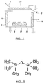
- the equipment used is a chamber 2 in which is created plasma chemistry (PACVD - Plasma Assisted Chemical Vapour Deposition.)
- RF antenna 4 On top of the chamber sits an RF antenna 4 on a quartz plate 6.
- An electrode 8 receives the substrate 10 with surfaces to be coated and is RF or / pulsed DC-biased via RF or / pulsed DC supply 12.
- the RF power supplies are matched at 13.56MHz.
- the magnetron arrangement 16, 18 helps to increase the plasma density in the chamber.
- Si0x-like coatings were applied by PACVD using, for example, SiH4 + Oxygen.
- a precursor named Hexadimethylsiloxane or HMDSO it is possible to modify easily the contact angle and surface energy.
- the plasma polymerisation of this precursor gives a good SiOx coating close to SiO2 but also a very hydrophobic SiOx-like (x ⁇ 2) coating and as a result the plasma parameters (pressure, power and ratio monomer / (oxygen + argon)) have been controlled to form a preferred water contact angle and surface energy of this SiOx-like coating.
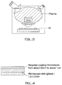
- the monomer used for this set of samples is the Hexadimethylsiloxane or HMDSO: [(CH 3 ) 3 Si] 2 O as shown in Figure 2 .
- HMDSO was decomposed in Oxygen and Argon plasma.
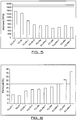
- Figure 3 illustrates a schematic view of the process within the chamber in which Plasma polymers SiOxCyHz were applied onto the substrates 10 to create a coating of the type shown in Figure 4 .
- the preferred thickness of the coating in Figure 4 is between 20nm to 2 ⁇ m.
- the assays involve an estimation of the 'fouling-release' performance of biomass in the form of young plants of Ulva that were allowed to colonise the test surfaces. This was measured by exposing the test surface to a known shear force produced by a water jet apparatus ( Source: Schultz MP, Finlay JA, Callow ME and Callow JA (2000) A turbulent channel flow apparatus for the determination of the adhesion strength of micro fouling organisms. Biofouling, 15, 243-251 ). The proportion of the Biomass removed under shear was then calculated as a percentage of that originally present before exposure to the shear forces.
- Figure 10 illustrates a controlled environment in the form of a plasma chamber which can be used to apply the coating to the surface of an article in accordance with one embodiment of the invention.
- the article 20 with the surface to be coated is placed in a holder which rotates in the chamber 22 and is RF or pulsed-DC biased.
- the chamber and apparatus provided is in the form of a closed field system by, in this embodiment, utilising four magnetrons with magnet polarities which act to retain a strong plasma within the coating chamber.
- the material from the target, 24, e.g. silicon, is deposited using the closed-field unbalanced magnetron sputtering method and with which magnetron 26 the target is located.
- the plasma within the chamber assists in the dissociation of the gases, e.g. HMDO + oxygen in the chamber.
- the material is deposited from both the solid target 24 and the gases simultaneously onto the sample.
- the coating is shown in Figure 11 in which the same is shown in cross section.
- the coating is multi layered coating in which the initial layer 28 which is applied to the surface of the article is Silicon in which case only material from the target 24 is deposited. Subsequent to that layer 30 is applied and formed of Si + O 2 .
- the final and external layer 32 of the coating is formed of Si + O 2 +HMDSO with the same being applied by the simultaneous deposition of material from the target and the gases within the chamber.
- a range of surface energies can be obtained by varying the HMDSO/O 2 ratio in the external layer 32 of the coating which corresponds to the change in the hydrocarbon content of the coating.
- coatings which can be deposited in accordance with the present disclosure are shown below: Code Base layer Si target current O 2 flow (sccm) HMDSO flow (arb.) Coating thickness ( ⁇ m) Surface energy A Si + SiO 2 3A 35 0.02 0.30 ⁇ SiO 2 B Si + SiO 2 3 A 30 0.03 0.20 ⁇ A C Si + SiO 2 3 A 25 0.04 0.50 ⁇ B D Si + SiO 2 3 A 20 0.05 0.50 ⁇ C
Landscapes
- Chemical & Material Sciences (AREA)
- Engineering & Computer Science (AREA)
- Chemical Kinetics & Catalysis (AREA)
- Materials Engineering (AREA)
- Organic Chemistry (AREA)
- Mechanical Engineering (AREA)
- Metallurgy (AREA)
- General Chemical & Material Sciences (AREA)
- Life Sciences & Earth Sciences (AREA)
- Geochemistry & Mineralogy (AREA)
- Physics & Mathematics (AREA)
- General Life Sciences & Earth Sciences (AREA)
- Thermal Sciences (AREA)
- General Engineering & Computer Science (AREA)
- Inorganic Chemistry (AREA)
- Plasma & Fusion (AREA)
- Paints Or Removers (AREA)
- Application Of Or Painting With Fluid Materials (AREA)
Description
- The invention to which this application relates is the provision of a form of coating to prevent or reduce biofouling of surfaces in aquatic environments. The surfaces in question may be typically the surface of heat exchangers, optical end-windows, filtering membranes, aquaculture systems or even ship and boat hulls, and other structures which are in regular contact with sea and freshwater water.
- Biofouling is caused by the accumulation of micro-organisms, plants and animals on surfaces such as those exposed to aquatic environment. This fouling can add to the weight of the surfaces, deface and indeed damage the same. Biofouling also has other environmental implications in energy costs and liberation of greenhouse gases. If the world fleet was totally fouled it is estimated that an extra 70.6M tonnes of fossil fuel would be burned per annum, liberating >210M tonnes CO2 and 5.6M tonnes SO2. Source: ttp://www.limnomar.de/download/18_Hunter.pdf
- Traditionally, biofouling has been controlled by the application of antifouling paints that contain biocides (i.e compounds that are toxic to the organisms) in particular within the ship industry. However, environmental regulations now require that antifouling paints, which are applied to surfaces, must not cause adverse effects to the environment and therefore many of the traditional products can no longer be used. There is therefore a need for more environmentally friendly ways of deterring marine and freshwater life from attaching to and potentially damaging surfaces to be developed whilst, at the same time preventing the problems that biofouling can cause.
- The most commonly used and most effective antifouling materials conventionally available for application to submerged marine structures are paints based on copper and organo-tin (TBT) but the use of the latter will be prohibited by 2008. A number of co-biocides are currently under environmental and legislative scrutiny (e.g the triazine herbicide Irgarol 1051) and restrictions on where they can be used will continue to grow, especially in Europe. For example, various directives associated with the European Union's 6th Environmental Action Plan will establish a framework for the protection of rivers and lakes, estuaries, coastal waters and groundwater to prevent further deterioration and protect and enhance the biodiversity of these ecosystems.
- While there are non-biocidal coating technologies to reduce biofouling of ship and boat hulls, there is a current shortage of environmentally-benign technologies to control biofouling in other contexts, both in marine and freshwater environments. Three relevant situations may be described.
- With regard to oceanographic instrumentation it has been found after prolonged research into marine-biofilm formation and methods of delaying or reducing it, that there are no known viable technologies to adequately protect the active components of sensors in most oceanographic instruments when deployed for long (several months) periods and subjected to significant fouling pressure.
- Another problematic area is with respect to heat exchanger tubes and plates. The fouling of heat exchangers in desalination and power plants causes an overall decline in plant efficiency at great economic cost. For example the presence of a biofilm on transfer surfaces of heat exchangers cooled by seawater reduces the heat transfer rate by 20 to 50% and incurs a global expenditure of over $15 billions per annum to control the problem (Source: Azis PKA, Al-Tisan I, Sasikumar N (2001) Desalination 135 : 69-82). The majority of current measures to control biofouling involve the use of biocides.
- The use of Microfiltration and ultrafiltration (MF/UF) membranes have become widely accepted as a viable alternative to conventional drinking water production and wastewater treatment technologies. The primary limitation to the adoption of membrane filtration for these applications is the occurrence of fouling with microorganisms and organic molecules. Fouling on membranes leads to a significant decline of the permeate flux, higher energy consumption, secondary bio-contamination by cells and metabolic products and, eventually, failure to meet the regulatory standards. Frequent cleaning of the membranes can be costly and may damage the membrane materials/barrier layers, which result in reduced membrane lifetime and selectivity. Conventional solutions to combat membrane fouling involve extensive pretreatment, and frequent cleaning with (often) aggressive chemicals, which impact on the environment. Fouling is the major problem that limits the use of membrane for seawater desalination (current market size of about 1 Billion Euros / year).
- In attempting to apply protective coatings to reduce the impact of biofouling significant technical problems exist. For example, heat exchangers need a very thin coating (typically below 1µm), and which is thermally conductive to avoid thermal transfer loss.
- Also, windows of, for example, oceanographic instrumentation need a transparent coating to a certain light spectrum and above a certain (relatively high) transmission coefficient while filtration membranes need a coating as thin as 20nm to avoid clogging the filtering pores.
- Consequently, in light of the problems currently experienced and the new environmental regulations there is an additional need for a new and practical solution and an aim of the present invention is to provide a means of preventing biofouling from occurring, or if it does, to promote weak adhesion of the foulants leading to their detachment.
-
US6383642 shows a method for protecting a surface against aquatic biofouling by applying a transparent silicone containing coating using low pressure RF Plasma CVD.
US 2006/096852 discloses a method using a CVD coating method with a silicone target and gas in relation to forming coatings for optical purposes. - In a first aspect of the invention there is provided a method of protecting a surface against aquatic biofouling by applying a thin film coating onto said surface to form a protective external coating thereon said method comprising placing the article with said surface on a holder for rotation in a chamber while applying the thin film coating within said chamber onto said surface, rotating the holder with the article placed thereon; applying a RF or pulsed DC bias to the said article, applying a layer of silicon material on said surface from a solid target of silicon material, applying a layer of SiO2 on top of the silicon layer and then characterised by applying, simultaneously, material from the solid target of silicon material and material from gases in the form of HMDSO and O2 introduced into the said chamber, to form the final and external layer of the said coating and the silicon material is deposited from the solid target using closed field unbalanced magnetron sputtering and operating an electrode in the chamber to assist in the breaking down of gases as the said final and external layer of the coating is formed.
- Typically the method can be used to protect against biofouling in both maritime and river environments.
- In one embodiment the coating is applied within a vacuum or atmospheric pressure environment and one or more deposition means are provided within said environment to deposit the selected material and/or combination of materials onto the surface or surfaces of an article which is to be exposed to potential biofouling in use. In one embodiment the coating is applied as a unitary layer. In an alternative embodiment the coating is applied as a series of layers, with successive layers having compositions and/or structures.
- In one embodiment the thickness of the coating which is applied is selected with respect to the particular usage of the surface to which the coating is to be applied, the environment to which the surface is to be exposed, and/or the duration of time for which the coating is required to be effective.
- In one embodiment the deposited coating is transparent and is applied to a surface to be used for optical purposes.
- In one embodiment the coating is applied to the surfaces of heat exchanger tubes or plates with respect to which seawater or freshwater is used as a coolant.
- In one embodiment the coating is applied to the surfaces of filtering membranes for drinking and waste water.
- In one embodiment the surface to be coated is placed in to a coating chamber in a controlled pressure and the coating is applied to the surface while in said chamber.
- Typically, respective selected gases flow into the chamber and are broken down and at least part of the coating is formed from substances deposited from the gas.
- In one embodiment,an RF or pulsed DC potential is applied to the surface to be coated.
- In on embodiment an electrode is operated to assist in breaking down the gases.
- In one embodiment in the coating method, respective selected gases flow into the chamber, are broken down and the substances which are deposited are from the gases.
In one embodiment precursor chemical gases are used with as low toxicity value as possible. Potentially either corrosive or toxic by-producers are trapped before release of the gases into the atmosphere.
Typically the coating which is applied has low surface energy and the surface morphology is suited to resist attachment of the fouling agents. - In accordance with the present disclosure there is therefore provided an article with at least one surface which is has a thin film coating including a layer of silicon material on said surface, a layer of SiO2 on top of the silicon layer and the final and external layer of SiOxCyHz, said coating applied thereto to form an external surface thereof.
Specific embodiments of the invention are now described with reference to the accompanying drawings, wherein:- -
Figure 1 illustrates a PACVD chamber in one embodiment; -
Figure 2 illustrates a HMDSO molecule; -
Figure 3 illustrates a plasma chamber in accordance with one embodiment of present disclosure -
Figure 4 illustrates a coating in accordance with one embodiment of the present disclosure; -
Figures 5 to 9b illustrate test results; -
Figure 10 illustrates a coating chamber of a type which can be used to apply the coating in accordance with one embodiment of the present disclosure and -
Figure 11 illustrates the formation of a coating in accordance with one embodiment of the present disclosure. - In one embodiment the equipment used is a
chamber 2 in which is created plasma chemistry (PACVD - Plasma Assisted Chemical Vapour Deposition.) On top of the chamber sits an RF antenna 4 on aquartz plate 6. Anelectrode 8 receives thesubstrate 10 with surfaces to be coated and is RF or / pulsed DC-biased via RF or /pulsed DC supply 12. The RF power supplies are matched at 13.56MHz.
Themagnetron arrangement
Si0x-like coatings were applied by PACVD using, for example, SiH4 + Oxygen.
By using a precursor named Hexadimethylsiloxane or HMDSO, it is possible to modify easily the contact angle and surface energy.
The deposited coatings and studies on their resistance to fouling organisms [Prof. JA Callow and team (University of Birmingham), Dr. Qi Zhao and team (University of Dundee), Dr P Willemsen and team (TNO)] have shown that the contact angle and surface energy can influence the adhesion strength of the green seaweed Ulva, the settlement and adhesion strength of freshwater bacteria, and the adhesion strength of marine bacteria1. - The plasma polymerisation of this precursor gives a good SiOx coating close to SiO2 but also a very hydrophobic SiOx-like (x<2) coating and as a result the plasma parameters (pressure, power and ratio monomer / (oxygen + argon)) have been controlled to form a preferred water contact angle and surface energy of this SiOx-like coating.
- The monomer used for this set of samples is the Hexadimethylsiloxane or HMDSO: [(CH3)3Si]2O as shown in
Figure 2 . - In this case the HMDSO was decomposed in Oxygen and Argon plasma.
- All the "unused" CHx groups coming from the decomposition of the monomer are transformed into CO2, CO, H2O, H2 compounds.
- As a function of the ratios of the gases used in the coating chamber and hence the process, a SiOxCyHz coating was developed with controlled CyHz/SiOx content.
-
Figure 3 illustrates a schematic view of the process within the chamber in which Plasma polymers SiOxCyHz were applied onto thesubstrates 10 to create a coating of the type shown inFigure 4 . - The preferred thickness of the coating in
Figure 4 is between 20nm to 2µm. - The tested chemistries also named "TCL40 series" can be described as follows:
Code Description Relative CyHz content TCL 40-1 All SiOxCyHz chemistries. The level of CyHz varies consistently across the series as described in the adjacent column. <40 TCL 40 - TCL 40+1>40 TCL 40+2>>40 TCL 40a >>>40 TCL 40a+1 >40a All samples were transparent. TCL 40b >>40a TCL 40b+1 =40b but higher deposition temperature Tb+1 >Tb TCL 40bt =40b, Tbt >>Tb TCL 40bt+1 =40bt, Tbt+1 >>>Tb - The University of Birmingham (UK), carried out biological evaluations on test samples using the green seaweed Ulva.The assays involve an estimation of the 'fouling-release' performance of biomass in the form of young plants of Ulva that were allowed to colonise the test surfaces. This was measured by exposing the test surface to a known shear force produced by a water jet apparatus (Source: Schultz MP, Finlay JA, Callow ME and Callow JA (2000) A turbulent channel flow apparatus for the determination of the adhesion strength of micro fouling organisms. Biofouling, 15, 243-251). The proportion of the Biomass removed under shear was then calculated as a percentage of that originally present before exposure to the shear forces. This is then compared with the percentage of removal from a standard test surface known to have 'fouling release' properties (a commonly used silicone elastomer (T2 Silastic) was used).
Figure 5 illustrates a typical set of results from this assay, it can be seen that specific formulations of the invention (TCL40bt, TCL40bt+1) show a performance exceeding that of the standard T2 Silastic, indicating a good fouling-release performance. - Regarding the evaluations carried on the attachment and detachment of biofilms formed from the freshwater bacterium Pseudomonas fluorescens at the University of Dundee, specific formulations of the invention showed very low biofilm formation (i.e. attachment and subsequent growth) of the bacterium compared to the test standard, which in this case is an epoxy resin surface (
Fig 6 ). Furthermore, those formulations that showed low biofilm formation also showed high levels of biofilm detachment (release of attached bacteria) (Fig. 7 ) compared with the detachment standard T2 Silastic. - Results for marine bacteria (carried out by TNO) show that detachment of biofilms of marine bacteria from all coatings in the TCL40 series are very similar to the T2 Silastic standard for fouling-release performance (
Figs. 9a and b ). -
Figure 10 illustrates a controlled environment in the form of a plasma chamber which can be used to apply the coating to the surface of an article in accordance with one embodiment of the invention. - In this example the
article 20 with the surface to be coated is placed in a holder which rotates in thechamber 22 and is RF or pulsed-DC biased. Preferably the chamber and apparatus provided is in the form of a closed field system by, in this embodiment, utilising four magnetrons with magnet polarities which act to retain a strong plasma within the coating chamber. The material from the target, 24, e.g. silicon, is deposited using the closed-field unbalanced magnetron sputtering method and with whichmagnetron 26 the target is located. At the same time, the plasma within the chamber assists in the dissociation of the gases, e.g. HMDO + oxygen in the chamber. Thus in this embodiment the material is deposited from both thesolid target 24 and the gases simultaneously onto the sample.
One form of the coating is shown inFigure 11 in which the same is shown in cross section. In this case the coating is multi layered coating in which theinitial layer 28 which is applied to the surface of the article is Silicon in which case only material from thetarget 24 is deposited. Subsequent to thatlayer 30 is applied and formed of Si + O2. The final andexternal layer 32 of the coating is formed of Si + O2 +HMDSO with the same being applied by the simultaneous deposition of material from the target and the gases within the chamber.
A range of surface energies can be obtained by varying the HMDSO/O2 ratio in theexternal layer 32 of the coating which corresponds to the change in the hydrocarbon content of the coating.
Examples of coatings which can be deposited in accordance with the present disclosure are shown below:Code Base layer Si target current O2 flow (sccm) HMDSO flow (arb.) Coating thickness (µm) Surface energy A Si + SiO2 3A 35 0.02 0.30 < SiO2 B Si + SiO2 3 A 30 0.03 0.20 <A C Si + SiO2 3 A 25 0.04 0.50 <B D Si + SiO2 3 A 20 0.05 0.50 <C - There is therefore provided a method and coating for reducing the effects and occurrence of biofouling without the use of biocides and thereby protecting surfaces against the effect of biofouling.
Claims (6)
- A method of protecting a surface against aquatic biofouling by applying a thin film coating onto said surface to form a protective external coating thereon said method comprising placing the article (10;20) with said surface on a holder for rotation in a chamber (2; 22) while applying the thin film coating within said chamber onto said surface, rotating the holder with the article placed thereon; applying a RF or pulsed DC bias (12) to the said article, applying a layer (28) of silicon material on said surface from a solid target of silicon material (24), applying a layer of SiO2 (30) on top of the silicon layer and then characterised by applying, simultaneously, material from the solid target of silicon material and material from gases in the form of HMDSO and 02 introduced into the said chamber, to form the final and external layer (32) of the said coating and the silicon material is deposited from the solid target using closed field unbalanced , magnetron sputtering and operating an electrode (8) in the chamber to assist in the breaking down of gases as the said final and external layer of the coating is formed.
- A method according to claim 1 wherein the deposited coating is transparent and is applied to a surface to be used for optical purposes.
- A method according to claim 1 wherein the coating is applied to the surface of a heat exchanger tube or plate with respect to which water is used as a coolant.
- A method according to claim 1 wherein the coating is applied to the surface of a filtering membrane for water.
- A method according to claim 1 wherein corrosive and/or toxic by-products are trapped before release of the gases into the atmosphere.
- A method according to claim 1 wherein a graded coating and/or multilayered coating is formed
Applications Claiming Priority (2)
| Application Number | Priority Date | Filing Date | Title |
|---|---|---|---|
| GBGB0717921.1A GB0717921D0 (en) | 2007-09-14 | 2007-09-14 | Coatings to resist and protect against aquatic biofouling |
| PCT/GB2008/003123 WO2009034359A1 (en) | 2007-09-14 | 2008-09-15 | Coatings to resist and protect against aquatic biofouling |
Publications (2)
| Publication Number | Publication Date |
|---|---|
| EP2188404A1 EP2188404A1 (en) | 2010-05-26 |
| EP2188404B1 true EP2188404B1 (en) | 2016-06-15 |
Family
ID=38658942
Family Applications (1)
| Application Number | Title | Priority Date | Filing Date |
|---|---|---|---|
| EP08806279.9A Active EP2188404B1 (en) | 2007-09-14 | 2008-09-15 | Method for the deposition of coatings to resist and protect against aquatic biofouling |
Country Status (4)
| Country | Link |
|---|---|
| US (1) | US8652588B2 (en) |
| EP (1) | EP2188404B1 (en) |
| GB (1) | GB0717921D0 (en) |
| WO (1) | WO2009034359A1 (en) |
Families Citing this family (14)
| Publication number | Priority date | Publication date | Assignee | Title |
|---|---|---|---|---|
| SA111320468B1 (en) * | 2010-05-26 | 2015-04-01 | الفا لافال كوربوريت ايه بي | Heat exchanger plates with anti-fouling properties |
| US9352981B2 (en) | 2011-02-18 | 2016-05-31 | Ut-Battelle, Llc | Harvesting contaminants from liquid |
| US8668812B2 (en) | 2011-02-18 | 2014-03-11 | Ut-Battelle, Llc | Superhydrophobic coated apparatus for liquid purification by evaporative condensation |
| JP2015504507A (en) | 2011-11-28 | 2015-02-12 | アルファ・ラバル・コーポレイト・エービー | Spiral heat exchanger with non-depositing properties |
| DK2597412T3 (en) | 2011-11-28 | 2014-08-11 | Alfa Laval Corp Ab | BLOCK-TYPE PLATE HEAT EXCHANGERS WITH ANTI-FAVORING PROPERTIES |
| GB201513760D0 (en) * | 2015-08-04 | 2015-09-16 | Teer Coatings Ltd | Improved coatings and method of applying the same |
| WO2017077106A1 (en) * | 2015-11-05 | 2017-05-11 | Bühler Alzenau Gmbh | Device and method for vacuum coating |
| US11709155B2 (en) | 2017-09-18 | 2023-07-25 | Waters Technologies Corporation | Use of vapor deposition coated flow paths for improved chromatography of metal interacting analytes |
| US12181452B2 (en) | 2017-09-18 | 2024-12-31 | Waters Technologies Corporation | Use of vapor deposition coated flow paths for improved chromatography of metal interacting analytes |
| US12180581B2 (en) | 2017-09-18 | 2024-12-31 | Waters Technologies Corporation | Use of vapor deposition coated flow paths for improved chromatography of metal interacting analytes |
| US11709156B2 (en) | 2017-09-18 | 2023-07-25 | Waters Technologies Corporation | Use of vapor deposition coated flow paths for improved analytical analysis |
| US12121829B2 (en) | 2019-02-27 | 2024-10-22 | Waters Technologies Corporation | Chromatographic seal and coated flow paths for minimizing analyte adsorption |
| US11918936B2 (en) | 2020-01-17 | 2024-03-05 | Waters Technologies Corporation | Performance and dynamic range for oligonucleotide bioanalysis through reduction of non specific binding |
| WO2022064447A1 (en) | 2020-09-24 | 2022-03-31 | Waters Technologies Corporation | Chromatographic hardware improvements for the separation of reactive molecules |
Citations (2)
| Publication number | Priority date | Publication date | Assignee | Title |
|---|---|---|---|---|
| JPH0894802A (en) * | 1994-09-27 | 1996-04-12 | Canon Inc | Optical element |
| US20050040034A1 (en) * | 2001-12-06 | 2005-02-24 | Ralf Landgraf | Coating method and coating |
Family Cites Families (12)
| Publication number | Priority date | Publication date | Assignee | Title |
|---|---|---|---|---|
| US5137701A (en) * | 1984-09-17 | 1992-08-11 | Mundt Randall S | Apparatus and method for eliminating unwanted materials from a gas flow line |
| JP2000070709A (en) | 1998-08-31 | 2000-03-07 | Kosei Kk | Material with titanium dioxide crystal orientation film |
| US6383642B1 (en) | 1999-04-09 | 2002-05-07 | Saint-Gobain Vitrage | Transparent substrate provided with hydrophobic/oleophobic coating formed by plasma CVD |
| FR2800731B1 (en) * | 1999-11-05 | 2002-01-18 | Saint Gobain Vitrage | TRANSPARENT SUBSTRATE HAVING A SILICON-DERIVED LAYER |
| JP3435136B2 (en) * | 2000-05-16 | 2003-08-11 | 日本板硝子株式会社 | Substrate hydrophilic treatment method |
| US6497803B2 (en) * | 2000-05-31 | 2002-12-24 | Isoflux, Inc. | Unbalanced plasma generating apparatus having cylindrical symmetry |
| DE10056242A1 (en) * | 2000-11-14 | 2002-05-23 | Alstom Switzerland Ltd | Condensation heat exchanger has heat exchanger surfaces having a coating consisting of a alternating sequence of layers made up of a hard layer with amorphous carbon or a plasma polymer |
| BRPI0507567A (en) * | 2004-02-10 | 2007-07-03 | Texas A & M Univ Sys | steam compression eveporation system and method |
| DE102004013306A1 (en) * | 2004-03-17 | 2005-10-06 | Behr Gmbh & Co. Kg | coating process |
| GB0410729D0 (en) * | 2004-05-14 | 2004-06-16 | Teer Coatings Ltd | Coating with hard wear and non-stick characteristics |
| ATE494400T1 (en) | 2004-11-05 | 2011-01-15 | Satisloh Ag | METHOD FOR APPLYING OPTICAL COATINGS |
| US20060219598A1 (en) * | 2005-01-10 | 2006-10-05 | Cody Ian A | Low energy surfaces for reduced corrosion and fouling |
-
2007
- 2007-09-14 GB GBGB0717921.1A patent/GB0717921D0/en not_active Ceased
-
2008
- 2008-09-15 EP EP08806279.9A patent/EP2188404B1/en active Active
- 2008-09-15 WO PCT/GB2008/003123 patent/WO2009034359A1/en not_active Ceased
- 2008-09-15 US US12/733,483 patent/US8652588B2/en not_active Expired - Fee Related
Patent Citations (2)
| Publication number | Priority date | Publication date | Assignee | Title |
|---|---|---|---|---|
| JPH0894802A (en) * | 1994-09-27 | 1996-04-12 | Canon Inc | Optical element |
| US20050040034A1 (en) * | 2001-12-06 | 2005-02-24 | Ralf Landgraf | Coating method and coating |
Also Published As
| Publication number | Publication date |
|---|---|
| US20100247928A1 (en) | 2010-09-30 |
| GB0717921D0 (en) | 2007-10-24 |
| EP2188404A1 (en) | 2010-05-26 |
| WO2009034359A1 (en) | 2009-03-19 |
| US8652588B2 (en) | 2014-02-18 |
Similar Documents
| Publication | Publication Date | Title |
|---|---|---|
| US8652588B2 (en) | Method of coating a surface of an article against aquatic bio fouling | |
| US20220186040A1 (en) | Industrial equipment article | |
| Yang et al. | Synergistic prevention of biofouling in seawater desalination by zwitterionic surfaces and low‐level chlorination | |
| Muthukumar et al. | Fouling and stability of polymers and composites in marine environment | |
| Sahoo et al. | Antibiofouling coatings for marine sensors: progress and perspectives on materials, methods, impacts, and field trial studies | |
| US7910648B2 (en) | Marine antifoulant coating | |
| Lakshmi et al. | Influence of surface characteristics on biofouling formed on polymers exposed to coastal sea waters of India | |
| Chen et al. | Poly (propylene carbonate) polyurethane self‐polishing coating for marine antifouling application | |
| EP3067324A1 (en) | Method for the preparation of electrodes of boron-doped nanocrystalline diamond, an electrode prepared by this method and a use thereof | |
| Chen et al. | Construction of corrosion resistant stainless steel mesh and the design for protecting optical window free from biofouling | |
| US5143545A (en) | Antifouling marine coatings | |
| Matsui et al. | Effectiveness of antifouling coatings and water flow in controlling attachment of the nuisance mussel Limnoperna fortunei | |
| Permeh et al. | Influence of macro-and microfouling on corrosion of steel bridge piles submerged in natural waters | |
| Yuan et al. | Modification of surface-oxidized copper alloy by coupling of viologens for inhibiting microbiologically influenced corrosion | |
| EP3655699A1 (en) | Light guides with coating for use in water | |
| Wissner et al. | Novel metabolite madeirone and neomarinone extracted from Streptomyces aculeoletus as marine antibiofilm and antifouling agents | |
| Dong et al. | Synergistic effect of copolymeric resin grafted 1, 2-benzisothiazol-3 (2 H)-one and heterocyclic groups as a marine antifouling coating | |
| Akesso et al. | Deposition parameters to improve the fouling-release properties of thin siloxane coatings prepared by PACVD | |
| Eashwar et al. | The interrelation of cathodic protection and marine macrofouling | |
| Tendero et al. | Nanocomposite thin film of Ag nanoparticles embedded in amorphous Al2O3 on optical sensors windows: Synthesis, characterization and targeted application towards transparency and anti-biofouling | |
| Nuraini et al. | The corrosivity and performance evaluation of antifouling paint exposed in seawater Muara Baru Port, Jakarta | |
| Polman et al. | Technologies for biofouling control and monitoring in desalination | |
| Pratikno et al. | System Impressed Current Anti Fouling (ICAF) against micro fouling (Bacteria) on ship’s cooling system | |
| Lim et al. | Preparation of a colored conductive paint electrode for electrochemical inactivation of bacteria | |
| Delauney et al. | Biofouling protection for marine environmental sensors. |
Legal Events
| Date | Code | Title | Description |
|---|---|---|---|
| PUAI | Public reference made under article 153(3) epc to a published international application that has entered the european phase |
Free format text: ORIGINAL CODE: 0009012 |
|
| 17P | Request for examination filed |
Effective date: 20100226 |
|
| AK | Designated contracting states |
Kind code of ref document: A1 Designated state(s): AT BE BG CH CY CZ DE DK EE ES FI FR GB GR HR HU IE IS IT LI LT LU LV MC MT NL NO PL PT RO SE SI SK TR |
|
| AX | Request for extension of the european patent |
Extension state: AL BA MK RS |
|
| DAX | Request for extension of the european patent (deleted) | ||
| 17Q | First examination report despatched |
Effective date: 20130308 |
|
| RIC1 | Information provided on ipc code assigned before grant |
Ipc: C23C 14/10 20060101ALI20151127BHEP Ipc: C23C 14/35 20060101ALI20151127BHEP Ipc: C23C 14/00 20060101AFI20151127BHEP Ipc: C23C 14/34 20060101ALI20151127BHEP Ipc: C23C 16/50 20060101ALI20151127BHEP Ipc: C03C 25/22 20060101ALI20151127BHEP Ipc: B01D 24/00 20060101ALI20151127BHEP Ipc: C23C 16/40 20060101ALI20151127BHEP Ipc: B05D 5/08 20060101ALI20151127BHEP Ipc: F28F 19/02 20060101ALI20151127BHEP Ipc: F28B 1/00 20060101ALI20151127BHEP Ipc: C03C 17/30 20060101ALI20151127BHEP Ipc: C03C 17/34 20060101ALI20151127BHEP Ipc: C03C 25/48 20060101ALI20151127BHEP |
|
| GRAP | Despatch of communication of intention to grant a patent |
Free format text: ORIGINAL CODE: EPIDOSNIGR1 |
|
| INTG | Intention to grant announced |
Effective date: 20160112 |
|
| RIN1 | Information on inventor provided before grant (corrected) |
Inventor name: TEER, DENNIS Inventor name: NAVABPOUR, PARNIA Inventor name: AKESSO, LAURENT |
|
| GRAS | Grant fee paid |
Free format text: ORIGINAL CODE: EPIDOSNIGR3 |
|
| GRAA | (expected) grant |
Free format text: ORIGINAL CODE: 0009210 |
|
| GRAT | Correction requested after decision to grant or after decision to maintain patent in amended form |
Free format text: ORIGINAL CODE: EPIDOSNCDEC |
|
| AK | Designated contracting states |
Kind code of ref document: B1 Designated state(s): AT BE BG CH CY CZ DE DK EE ES FI FR GB GR HR HU IE IS IT LI LT LU LV MC MT NL NO PL PT RO SE SI SK TR |
|
| REG | Reference to a national code |
Ref country code: CH Ref legal event code: EP Ref country code: GB Ref legal event code: FG4D |
|
| REG | Reference to a national code |
Ref country code: FR Ref legal event code: PLFP Year of fee payment: 9 |
|
| REG | Reference to a national code |
Ref country code: IE Ref legal event code: FG4D |
|
| REG | Reference to a national code |
Ref country code: AT Ref legal event code: REF Ref document number: 806554 Country of ref document: AT Kind code of ref document: T Effective date: 20160715 |
|
| REG | Reference to a national code |
Ref country code: DE Ref legal event code: R096 Ref document number: 602008044731 Country of ref document: DE |
|
| REG | Reference to a national code |
Ref country code: LT Ref legal event code: MG4D |
|
| REG | Reference to a national code |
Ref country code: NL Ref legal event code: MP Effective date: 20160615 |
|
| PG25 | Lapsed in a contracting state [announced via postgrant information from national office to epo] |
Ref country code: FI Free format text: LAPSE BECAUSE OF FAILURE TO SUBMIT A TRANSLATION OF THE DESCRIPTION OR TO PAY THE FEE WITHIN THE PRESCRIBED TIME-LIMIT Effective date: 20160615 Ref country code: LT Free format text: LAPSE BECAUSE OF FAILURE TO SUBMIT A TRANSLATION OF THE DESCRIPTION OR TO PAY THE FEE WITHIN THE PRESCRIBED TIME-LIMIT Effective date: 20160615 Ref country code: NO Free format text: LAPSE BECAUSE OF FAILURE TO SUBMIT A TRANSLATION OF THE DESCRIPTION OR TO PAY THE FEE WITHIN THE PRESCRIBED TIME-LIMIT Effective date: 20160915 |
|
| REG | Reference to a national code |
Ref country code: AT Ref legal event code: MK05 Ref document number: 806554 Country of ref document: AT Kind code of ref document: T Effective date: 20160615 |
|
| PG25 | Lapsed in a contracting state [announced via postgrant information from national office to epo] |
Ref country code: NL Free format text: LAPSE BECAUSE OF FAILURE TO SUBMIT A TRANSLATION OF THE DESCRIPTION OR TO PAY THE FEE WITHIN THE PRESCRIBED TIME-LIMIT Effective date: 20160615 Ref country code: GR Free format text: LAPSE BECAUSE OF FAILURE TO SUBMIT A TRANSLATION OF THE DESCRIPTION OR TO PAY THE FEE WITHIN THE PRESCRIBED TIME-LIMIT Effective date: 20160916 Ref country code: LV Free format text: LAPSE BECAUSE OF FAILURE TO SUBMIT A TRANSLATION OF THE DESCRIPTION OR TO PAY THE FEE WITHIN THE PRESCRIBED TIME-LIMIT Effective date: 20160615 Ref country code: SE Free format text: LAPSE BECAUSE OF FAILURE TO SUBMIT A TRANSLATION OF THE DESCRIPTION OR TO PAY THE FEE WITHIN THE PRESCRIBED TIME-LIMIT Effective date: 20160615 Ref country code: HR Free format text: LAPSE BECAUSE OF FAILURE TO SUBMIT A TRANSLATION OF THE DESCRIPTION OR TO PAY THE FEE WITHIN THE PRESCRIBED TIME-LIMIT Effective date: 20160615 |
|
| PG25 | Lapsed in a contracting state [announced via postgrant information from national office to epo] |
Ref country code: IT Free format text: LAPSE BECAUSE OF FAILURE TO SUBMIT A TRANSLATION OF THE DESCRIPTION OR TO PAY THE FEE WITHIN THE PRESCRIBED TIME-LIMIT Effective date: 20160615 Ref country code: EE Free format text: LAPSE BECAUSE OF FAILURE TO SUBMIT A TRANSLATION OF THE DESCRIPTION OR TO PAY THE FEE WITHIN THE PRESCRIBED TIME-LIMIT Effective date: 20160615 Ref country code: SK Free format text: LAPSE BECAUSE OF FAILURE TO SUBMIT A TRANSLATION OF THE DESCRIPTION OR TO PAY THE FEE WITHIN THE PRESCRIBED TIME-LIMIT Effective date: 20160615 Ref country code: IS Free format text: LAPSE BECAUSE OF FAILURE TO SUBMIT A TRANSLATION OF THE DESCRIPTION OR TO PAY THE FEE WITHIN THE PRESCRIBED TIME-LIMIT Effective date: 20161015 Ref country code: RO Free format text: LAPSE BECAUSE OF FAILURE TO SUBMIT A TRANSLATION OF THE DESCRIPTION OR TO PAY THE FEE WITHIN THE PRESCRIBED TIME-LIMIT Effective date: 20160615 Ref country code: CZ Free format text: LAPSE BECAUSE OF FAILURE TO SUBMIT A TRANSLATION OF THE DESCRIPTION OR TO PAY THE FEE WITHIN THE PRESCRIBED TIME-LIMIT Effective date: 20160615 |
|
| PG25 | Lapsed in a contracting state [announced via postgrant information from national office to epo] |
Ref country code: ES Free format text: LAPSE BECAUSE OF FAILURE TO SUBMIT A TRANSLATION OF THE DESCRIPTION OR TO PAY THE FEE WITHIN THE PRESCRIBED TIME-LIMIT Effective date: 20160615 Ref country code: PL Free format text: LAPSE BECAUSE OF FAILURE TO SUBMIT A TRANSLATION OF THE DESCRIPTION OR TO PAY THE FEE WITHIN THE PRESCRIBED TIME-LIMIT Effective date: 20160615 Ref country code: BE Free format text: LAPSE BECAUSE OF NON-PAYMENT OF DUE FEES Effective date: 20160615 Ref country code: AT Free format text: LAPSE BECAUSE OF FAILURE TO SUBMIT A TRANSLATION OF THE DESCRIPTION OR TO PAY THE FEE WITHIN THE PRESCRIBED TIME-LIMIT Effective date: 20160615 Ref country code: PT Free format text: LAPSE BECAUSE OF FAILURE TO SUBMIT A TRANSLATION OF THE DESCRIPTION OR TO PAY THE FEE WITHIN THE PRESCRIBED TIME-LIMIT Effective date: 20161017 |
|
| REG | Reference to a national code |
Ref country code: DE Ref legal event code: R097 Ref document number: 602008044731 Country of ref document: DE |
|
| PLBE | No opposition filed within time limit |
Free format text: ORIGINAL CODE: 0009261 |
|
| STAA | Information on the status of an ep patent application or granted ep patent |
Free format text: STATUS: NO OPPOSITION FILED WITHIN TIME LIMIT |
|
| PG25 | Lapsed in a contracting state [announced via postgrant information from national office to epo] |
Ref country code: MC Free format text: LAPSE BECAUSE OF FAILURE TO SUBMIT A TRANSLATION OF THE DESCRIPTION OR TO PAY THE FEE WITHIN THE PRESCRIBED TIME-LIMIT Effective date: 20160615 |
|
| REG | Reference to a national code |
Ref country code: CH Ref legal event code: PL |
|
| 26N | No opposition filed |
Effective date: 20170316 |
|
| PG25 | Lapsed in a contracting state [announced via postgrant information from national office to epo] |
Ref country code: DK Free format text: LAPSE BECAUSE OF FAILURE TO SUBMIT A TRANSLATION OF THE DESCRIPTION OR TO PAY THE FEE WITHIN THE PRESCRIBED TIME-LIMIT Effective date: 20160615 |
|
| REG | Reference to a national code |
Ref country code: IE Ref legal event code: MM4A |
|
| REG | Reference to a national code |
Ref country code: FR Ref legal event code: PLFP Year of fee payment: 10 |
|
| PG25 | Lapsed in a contracting state [announced via postgrant information from national office to epo] |
Ref country code: CH Free format text: LAPSE BECAUSE OF NON-PAYMENT OF DUE FEES Effective date: 20160930 Ref country code: LI Free format text: LAPSE BECAUSE OF NON-PAYMENT OF DUE FEES Effective date: 20160930 Ref country code: IE Free format text: LAPSE BECAUSE OF NON-PAYMENT OF DUE FEES Effective date: 20160915 |
|
| PG25 | Lapsed in a contracting state [announced via postgrant information from national office to epo] |
Ref country code: SI Free format text: LAPSE BECAUSE OF FAILURE TO SUBMIT A TRANSLATION OF THE DESCRIPTION OR TO PAY THE FEE WITHIN THE PRESCRIBED TIME-LIMIT Effective date: 20160615 Ref country code: LU Free format text: LAPSE BECAUSE OF NON-PAYMENT OF DUE FEES Effective date: 20160915 |
|
| PG25 | Lapsed in a contracting state [announced via postgrant information from national office to epo] |
Ref country code: CY Free format text: LAPSE BECAUSE OF FAILURE TO SUBMIT A TRANSLATION OF THE DESCRIPTION OR TO PAY THE FEE WITHIN THE PRESCRIBED TIME-LIMIT Effective date: 20160615 Ref country code: HU Free format text: LAPSE BECAUSE OF FAILURE TO SUBMIT A TRANSLATION OF THE DESCRIPTION OR TO PAY THE FEE WITHIN THE PRESCRIBED TIME-LIMIT; INVALID AB INITIO Effective date: 20080915 |
|
| PG25 | Lapsed in a contracting state [announced via postgrant information from national office to epo] |
Ref country code: MT Free format text: LAPSE BECAUSE OF NON-PAYMENT OF DUE FEES Effective date: 20160930 Ref country code: TR Free format text: LAPSE BECAUSE OF FAILURE TO SUBMIT A TRANSLATION OF THE DESCRIPTION OR TO PAY THE FEE WITHIN THE PRESCRIBED TIME-LIMIT Effective date: 20160615 |
|
| REG | Reference to a national code |
Ref country code: FR Ref legal event code: PLFP Year of fee payment: 11 |
|
| PG25 | Lapsed in a contracting state [announced via postgrant information from national office to epo] |
Ref country code: BG Free format text: LAPSE BECAUSE OF FAILURE TO SUBMIT A TRANSLATION OF THE DESCRIPTION OR TO PAY THE FEE WITHIN THE PRESCRIBED TIME-LIMIT Effective date: 20160615 |
|
| PGFP | Annual fee paid to national office [announced via postgrant information from national office to epo] |
Ref country code: FR Payment date: 20180711 Year of fee payment: 11 Ref country code: DE Payment date: 20180713 Year of fee payment: 11 |
|
| REG | Reference to a national code |
Ref country code: DE Ref legal event code: R119 Ref document number: 602008044731 Country of ref document: DE |
|
| PG25 | Lapsed in a contracting state [announced via postgrant information from national office to epo] |
Ref country code: DE Free format text: LAPSE BECAUSE OF NON-PAYMENT OF DUE FEES Effective date: 20200401 |
|
| PG25 | Lapsed in a contracting state [announced via postgrant information from national office to epo] |
Ref country code: FR Free format text: LAPSE BECAUSE OF NON-PAYMENT OF DUE FEES Effective date: 20190930 |
|
| P01 | Opt-out of the competence of the unified patent court (upc) registered |
Effective date: 20230403 |
|
| PGFP | Annual fee paid to national office [announced via postgrant information from national office to epo] |
Ref country code: GB Payment date: 20250729 Year of fee payment: 18 |