EP2187546A1 - Control information communication method and its device - Google Patents
Control information communication method and its device Download PDFInfo
- Publication number
- EP2187546A1 EP2187546A1 EP07806499A EP07806499A EP2187546A1 EP 2187546 A1 EP2187546 A1 EP 2187546A1 EP 07806499 A EP07806499 A EP 07806499A EP 07806499 A EP07806499 A EP 07806499A EP 2187546 A1 EP2187546 A1 EP 2187546A1
- Authority
- EP
- European Patent Office
- Prior art keywords
- control data
- control channel
- control
- multiplexing
- format
- Prior art date
- Legal status (The legal status is an assumption and is not a legal conclusion. Google has not performed a legal analysis and makes no representation as to the accuracy of the status listed.)
- Withdrawn
Links
Images










Classifications
-
- H—ELECTRICITY
- H04—ELECTRIC COMMUNICATION TECHNIQUE
- H04L—TRANSMISSION OF DIGITAL INFORMATION, e.g. TELEGRAPHIC COMMUNICATION
- H04L1/00—Arrangements for detecting or preventing errors in the information received
- H04L1/0001—Systems modifying transmission characteristics according to link quality, e.g. power backoff
- H04L1/0023—Systems modifying transmission characteristics according to link quality, e.g. power backoff characterised by the signalling
- H04L1/0028—Formatting
-
- H—ELECTRICITY
- H04—ELECTRIC COMMUNICATION TECHNIQUE
- H04L—TRANSMISSION OF DIGITAL INFORMATION, e.g. TELEGRAPHIC COMMUNICATION
- H04L1/00—Arrangements for detecting or preventing errors in the information received
- H04L1/0001—Systems modifying transmission characteristics according to link quality, e.g. power backoff
- H04L1/0023—Systems modifying transmission characteristics according to link quality, e.g. power backoff characterised by the signalling
- H04L1/0032—Without explicit signalling
-
- H—ELECTRICITY
- H04—ELECTRIC COMMUNICATION TECHNIQUE
- H04L—TRANSMISSION OF DIGITAL INFORMATION, e.g. TELEGRAPHIC COMMUNICATION
- H04L1/00—Arrangements for detecting or preventing errors in the information received
- H04L1/12—Arrangements for detecting or preventing errors in the information received by using return channel
- H04L1/16—Arrangements for detecting or preventing errors in the information received by using return channel in which the return channel carries supervisory signals, e.g. repetition request signals
- H04L1/1607—Details of the supervisory signal
- H04L1/1671—Details of the supervisory signal the supervisory signal being transmitted together with control information
-
- H—ELECTRICITY
- H04—ELECTRIC COMMUNICATION TECHNIQUE
- H04L—TRANSMISSION OF DIGITAL INFORMATION, e.g. TELEGRAPHIC COMMUNICATION
- H04L5/00—Arrangements affording multiple use of the transmission path
- H04L5/0001—Arrangements for dividing the transmission path
- H04L5/0003—Two-dimensional division
- H04L5/0005—Time-frequency
-
- H—ELECTRICITY
- H04—ELECTRIC COMMUNICATION TECHNIQUE
- H04L—TRANSMISSION OF DIGITAL INFORMATION, e.g. TELEGRAPHIC COMMUNICATION
- H04L5/00—Arrangements affording multiple use of the transmission path
- H04L5/003—Arrangements for allocating sub-channels of the transmission path
- H04L5/0048—Allocation of pilot signals, i.e. of signals known to the receiver
-
- H—ELECTRICITY
- H04—ELECTRIC COMMUNICATION TECHNIQUE
- H04L—TRANSMISSION OF DIGITAL INFORMATION, e.g. TELEGRAPHIC COMMUNICATION
- H04L5/00—Arrangements affording multiple use of the transmission path
- H04L5/003—Arrangements for allocating sub-channels of the transmission path
- H04L5/0053—Allocation of signalling, i.e. of overhead other than pilot signals
-
- H—ELECTRICITY
- H04—ELECTRIC COMMUNICATION TECHNIQUE
- H04L—TRANSMISSION OF DIGITAL INFORMATION, e.g. TELEGRAPHIC COMMUNICATION
- H04L1/00—Arrangements for detecting or preventing errors in the information received
- H04L1/0001—Systems modifying transmission characteristics according to link quality, e.g. power backoff
- H04L1/0023—Systems modifying transmission characteristics according to link quality, e.g. power backoff characterised by the signalling
- H04L1/0026—Transmission of channel quality indication
Definitions
- control data communication method and an apparatus for the control data communication method, such as, a control data communication method that multiplexes various independent control data, transmits the data by using a control channel, and separates the control data received from the control channel, and an apparatus for the control data communication method.
- LTE Long Term Evolution
- UL grant DL Scheduling Information
- the UL grant is used for permitting transmission of uplink data and designating parameters of the uplink data.
- a mobile station UE: User Equipment
- the UE performs transmission of uplink data.
- the DL Scheduling information is used for designating parameters of downlink data to be transmitted immediately after.
- a mobile station performs reception of downlink data when receiving the DL Scheduling information and transmits Ack or Nack (Ack/Nack) by using an uplink control channel according to check results of CRC (Cyclic Redundancy Check).
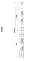
- FIG. 1 illustrates an example of an uplink control channel format that transmits Ack/Nack.
- 1 sub-frame is, for example, 1.0 ms and formed of two slots. Each slot is formed of 7 blocks.
- RS reference signal
- RS reference signal
- the uplink control channel is also used for transmitting, for example, CQIs (Channel Quality Indicator).
- CQI Channel Quality Indicator
- the CQI is an index representing transmission path status of a downlink and is normally transmitted from a base station at a predetermined frequency.
- FIG. 1B illustrates an example of an uplink control channel format that transmits CQIs.
- SC-FDMA Single Carrier Frequency Division Multiple Access
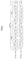
- FIG. 2 illustrates an example of an uplink control channel format according to a related art example.
- the Ack/Nack and the CQI are simply time-divisionally multiplexed.
- FIG. 3 illustrates another example of an uplink control channel format according to a related art example.
- Ack is multiplexed for each slot by modulating a reference signal with ⁇ 1, 1 ⁇ .
- Nack is multiplexed for each slot by modulating a reference signal with ⁇ 1, -1 ⁇ .
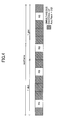
- FIG. 4 illustrates another example of an uplink control channel format according to a related art example.
- Ack/Nack and CQI are encoded together and contained in five blocks of each slot.
- Ack/Nack signals are received and determined by a base station (also referred to as "end”: evolved Node B).
- a base station also referred to as "end”: evolved Node B.
- end also referred to as "end”: evolved Node B.
- DTX transmission Ack/Nack (DTX transmission). Therefore, it is necessary for the base station to determine the three values of Ack/Nack/DTX.
- the multiplexing methods of the related art examples illustrated in FIGS. 2-4 are not formats allowing easy determination of the three values Ack/Nack/DTX.
- the base station erroneously determines DTX as Ack, retransmission in Layer 1 cannot be performed and loss of packets occurs. As a result, throughput is significantly degraded.
- a control data communication method for multiplexing and transmitting plural mutually independent types of control data by using a control channel and for separating the control data received from the control channel, the control data communication method including: changing and transmitting patterns of reference signals included in the control channel according to a format for multiplexing the control data; detecting the format for multiplexing the transmitted control data according to the pattern of the reference signals included in the control channel; and separating the control data in correspondence with the detected format.
- SC-FDMA Single carrier FDMA
- transmission frequency bandwidth may change for each sub-frame; it is, however, limited to using a single frequency bandwidth for performing a single transmission. Therefore, for example, data signals and control data cannot be simultaneously transmitted with different frequency bandwidths. Accordingly, with the LTE, in a case where data signals are to be transmitted simultaneously with the transmission of control data, the control data are multiplexed in the same bandwidth as the data signals. On the other hand, in a case of not simultaneously transmitting the control data and data signals, the control data are transmitted with a bandwidth different from the bandwidth normally used for transmitting data signals (as described below).
- FIG. 5 illustrates a configuration of a channel for LTE uplink.
- the horizontal axis represents a time axis and the vertical axis represents a frequency axis.
- the control channel in an LTE uplink is assigned to, for example, both sides of a system bandwidth.
- control data are transmitted in the control channel in units of subframes (1.0 ms). However, in order to obtain frequency diversity gain, frequency hopping is performed for each slot (0.5 ms).
- the user equipment measures reception quality of a downlink, quantizes the quality as CQI, and periodically transmits the CQI at predetermined fixed periods.
- the user equipment In a case where the user equipment receives a downlink signal, the user equipment transmits Ack/Nack according to the result of a CRC check after decoding the downlink signal.
- the timing for transmitting the Ack/Nack is not predetermined. Accordingly, in some case, it may be necessary to transmit Ack/Nack at the same time of transmitting CQI. In this case, CQI and Ack/Nack are multiplexed and transmitted with the bandwidth used for transmitting CQI.
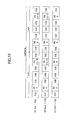
- FIG. 6 illustrates an uplink control channel format according to a first embodiment of the present invention.
- one sub-frame consists of, for example, two slots of 1.0 ms, in which each slot consists of seven blocks.
- (A) of FIG. 6 illustrates a case where there is only CQI (i.e. a case where DTX is multiplexed with CQI).
- the reference signals in two of the blocks of the same slot are modulated with the same phase (i.e. modulated with ⁇ 1, 1 ⁇ ).
- FIG. 6 illustrates a case where Ack/Nack and CQI are time-division multiplexed.
- the reference signals in two of the blocks of the same slot are modulated with a reversed phase (i.e. modulated with ⁇ 1, -1 ⁇ ).
- CQI and Ack/Nack are allocated to the slots on the left and right.
- a base station can first determine which format is used for transmission by determining the phase of the received reference signals in the same slot. Based on the result of the determination, Ack/Nack and DTX can be demodulated. As a result, significant degrading of throughput due to erroneously determining DTX as Ack/Nack can be prevented.
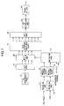
- FIG. 7 illustrates a block diagram of an uplink control channel transmission part of a user equipment according to a first embodiment of the present invention.
- Ack/Nack of 1 or 2 bits is repetitively encoded in an encoding part 11, modulated in a modulating part 12, and supplied to a switching part 13.
- CQI of 4 or 5 bits is convolutionally encoded in an encoding part 14, modulated in a modulating part 15, and supplied to the switching part 13.
- the switching part 13 sequentially selects and switches the CQI, +1, CQI, CQI, +1, and CQI illustrated in (A) of FIG. 6 in block units. Further, the CQI, +1, Ack/Nack, CQI, Ack/Nack, -1, CQI illustrated in (B) of FIG. 6 are sequentially selected and switched and supplied to a multiplying part 20 in block units.
- a ZC sequence part 18 generates, for example, a ZC sequence of 12 symbols.
- the ZC sequence is converted into parallel form by a S/P (serial/parallel converting) part 19 and supplied to the multiplying part 20.
- the multiplying part 20 multiplies the ZC sequence with the signals supplied from the switching part 13 and supplies it to a sub-carrier mapping part 21 in parallel.
- the sub-carrier mapping part 21 maps the signals from the multiplying part 20 to a frequency bandwidth of a sub-carrier of the control channel illustrated in FIG. 5 . Then, because the signals have been processed as signals of a frequency domain until this stage, the signals are converted into signals of time domain by performing inverse Fourier transformation in an IFFT (Inverse Fast Fourier Transform) part 22, are added with CP (Cyclic Prefix) in a CP adding part 23, and are transmitted from a transmitting part 24.
- IFFT Inverse Fast Fourier Transform
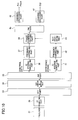
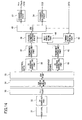
- FIG. 8 illustrates a block diagram of an uplink control channel receiving part of a base station according to a first embodiment of the present invention.
- signals received at a receiver 31 are supplied to a CP removing part 32 by which a CP (Cyclic Prefix) is removed therefrom. Then, the signals are converted into frequency domain signals in block units by a FFT (Fast Fourier Transform) part 33.
- FFT Fast Fourier Transform
- the sub-carrier de-mapping part 34 performs a sub-carrier de-mapping process and separates control data (Ack/Nack, CQI) and reference signals according to the formats illustrated in (A) and (B) of FIG. 6 .
- a ZC sequence cancelling part 36 removes the ZC sequence from the control data by multiplying the control data with a complex conjugate sequence. Then, a frequency averaging part 37 obtains the average on the frequency axis from the control data and supplies the average to a phase compensating part 38.
- a ZC cancelling part 41 removes the ZC sequence from the reference signals by multiplying the reference signals with a complex conjugate sequence. Then, a frequency averaging part 42 obtains the average on the frequency axis and supplies the average to a format determining part 43 and a slot averaging part 44.
- the format determining part 43 obtains correlation values of the averaged reference signal for a pattern ⁇ +1, +1 ⁇ and for a pattern ⁇ +1, -1 ⁇ and determines that the one having greater correlation value is the pattern of the actually transmitted reference signal, that is, the transmitted format. In other words, the format determining part 43 determines whether the transmitted format is a format including only CQI (multiplexed with DTX) as illustrated in (A) of FIG. 6 or a format including Ack/Nack multiplexed with CQI as illustrated in (B) of FIG. 6 depending on whether the reference signals in the slot have the same phase or the opposite phase. The format determining part 43 supplies the determination result to a slot averaging part 44, a SW part 45, and the channel decoding parts 46, 47. Further, in a case where the format includes only CQI, DTX is output.
- the slot averaging part 44 averages the reference signals in a slot either in a case where the reference signals in a slot have the same phase (a case where the pattern is ⁇ +1, +1 ⁇ ) or the opposite phase (a case where the pattern is ⁇ +1, - 1 ⁇ ).
- the phase compensating part 38 performs phase compensation of the control data according to phase data of the reference signals.
- the SW part 45 separates the control data into Ack/Nack and CQI in accordance with the format.
- the channel decoding part 46 decodes the channel of the Ack/Nack and outputs the Ack/Nack.
- the channel decoding part 47 decodes the channel of the CQI and outputs the CQI.
- the encoding rate is 0.25 when encoding 5 bits representing the 32 patterns with 20 bits per sub-frame (5 blocks) (in a case of QPSK).
- FIG. 9 illustrates a block configuration of an uplink control channel transmitting part in a case where a format according to a related art example of FIG. 2 is used
- FIG. 10 illustrates a block configuration of an uplink control channel receiving part in a case where a format according to a related art example of FIG. 2 is used.
- like components are denoted with like reference numerals as those of FIG. 7 and FIG. 8 .
- FIG. 9 only +1 is supplied from a terminal 16 to the switching part 13. That is, reference signals are supplied where Ack/Nack is multiplexed or where DTX is multiplexed.
- the switching part 13 of FIG. 7 supplies different reference signals according to a case where Ack/Nack is multiplexed and where DTX is multiplexed.
- reference signals are preferred to have constant amplitude in the frequency region (i.e. the autocorrelation of a given periodic time shift is 0) in order to improve the accuracy of frequency estimation in the frequency region.
- PAPR Peak-to-Average Power Ratio
- a ZC (Zadoff-Chu) sequence is proposed.
- the Formula thereof is illustrated below.
- "k” represents a symbol number and "n” represents an index in a time direction. If the integers of "k” and “L” are both primary, the sequence length is "L".
- FIG. 11 illustrates a modified example of an uplink control channel format according to the first embodiment of the present invention.
- (A) of FIG. 11 illustrates a case where there is only CQI (i.e. a case where DTX is multiplexed with CQI).
- the reference signals in two of the blocks of the same slot are modulated with the same phase (i.e. modulated with ⁇ 1, 1 ⁇ ). This is the same as (A) of FIG. 6 .
- FIG. 11 illustrates a case where Ack/Nack and CQI are time-division multiplexed.
- the reference signals in two of the blocks of the same slot are modulated with a reversed phase (i.e. modulated with ⁇ 1, -1 ⁇ ).
- CQI is allocated to the slot of the left side and Ack/Nack is allocated to the slot of the right side.
- FIG. 12 illustrates an uplink control channel format according to a second embodiment of the present invention.
- (A) of FIG. 12 illustrates a case where there is only CQI (i.e. a case where DTX is multiplexed with CQI).
- the reference signals in two of the blocks of the same slot are modulated with the same phase (i.e. modulated with ⁇ 1, 1 ⁇ ). This is the same as (A) of FIG. 6 .
- FIG. 12 illustrates a case where Ack and CQI or Nack and CQI are combined and encoded (simultaneous encoding of Ack/Nack and CQI).
- the reference signals in two blocks of the same slot are modulated with a reversed phase (i.e. modulated with ⁇ 1, -1 ⁇ ).
- a base station can first determine which format is used for transmission by determining the phase of received reference signals in the same slot. Based on the result of the determination, Ack/Nack and DTX can be demodulated. As a result, significant degrading of throughput due to erroneously determining DTX as Ack/Nack can be prevented.
- FIG. 13 illustrates a block diagram of an uplink control channel transmitting part of a user equipment according to a second embodiment of the present invention.
- Ack/Nack of 1 or 2 bits and CQI of 5 bits which total 6 or 7 bits are encoded by an encoding part 51, modulated by a modulating part 52, and supplied to the switching part 13.
- the switching part 13 sequentially selects and switches the CQI, +1, CQI, CQI, CQI, +1, and CQI illustrated in (A) of FIG. 12 in block units. Further, the Ack/Nack + CQI, +1, Ack/Nack + CQI, Ack/Nack + CQI, Ack/Nack + CQI, -1, and Ack/Nack + CQI illustrated in (B) of FIG. 12 are sequentially selected and switched and supplied to the multiplying part 20 in block units.
- the ZC sequence part 18 generates, for example, a ZC sequence of 12 symbols.
- the ZC sequence is converted into parallel form by the S/P part 19 and supplied to the multiplying part 20.
- the multiplying part 20 multiplies the ZC sequence with the signals supplied from the switching part 13 and supplies it to the sub-carrier mapping part 21 in parallel.
- the sub-carrier mapping part 21 maps the signals from the multiplying part 20 to a frequency bandwidth of a sub-carrier of the control channel illustrated in FIG. 5 . Then, because the signals have been processed as signals of a frequency domain until this stage, the signals are converted into signals of time domain by performing inverse Fourier transformation in an IFFT (Inverse Fast Fourier Transform) part 22, are added with CP (Cyclic Prefix) in the CP adding part 23, and are transmitted from the transmitter 24.
- IFFT Inverse Fast Fourier Transform
- FIG. 14 illustrates a block diagram of an uplink control channel receiving part of a base station according to the second embodiment of the present invention.
- signals received at the receiver 31 are supplied to the CP removing part 32 by which a CP is removed therefrom. Then, the signals are converted into frequency domain signals in block units by the FFT (Fast Fourier Transform) part 33.
- FFT Fast Fourier Transform
- the sub-carrier de-mapping part 34 performs a sub-carrier de-mapping process and separates control data (Ack/Nack + CQI, CQI) and reference signals according to the formats illustrated in (A) and (B) of FIG. 12 .
- the ZC sequence cancelling part 36 removes the ZC sequence from the control data by multiplying the control data with a complex conjugate sequence. Then, the frequency averaging part 37 obtains the average on the frequency axis from the control data and supplies the average to the phase compensating part 38.
- the ZC cancelling part 41 removes the ZC sequence from the reference signals by multiplying the reference signals with a complex conjugate sequence. Then, the frequency averaging part 42 obtains the average on the frequency axis and supplies the average to the format determining part 43 and the slot averaging part 44.
- the format determining part 43 obtains correlation values of the averaged reference signal for a pattern ⁇ +1, +1 ⁇ and for a pattern ⁇ +1, -1 ⁇ and determines that the one having a greater correlation value is the pattern of the actually transmitted reference signal, that is, the transmitted format. In other words, the format determining part 43 determines whether the transmitted format is a format including only CQI (multiplexed with DTX) as illustrated in (A) of FIG. 12 or a format including Ack/Nack multiplexed with CQI as illustrated in (B) of FIG. 12 depending on whether the reference signals in a slot have the same phase or the opposite phase. The format determining part 43 supplies the determination result to the slot averaging part 44 and the SW part 45. Further, in a case where the format includes only CQI, DTX is output.
- the slot averaging part 44 averages the reference signals in a slot either in a case where the reference signals in a slot have the same phase (a case where the pattern is ⁇ +1, +1 ⁇ ) or the opposite phase (a case where the pattern is ⁇ +1, - 1 ⁇ ).
- the phase compensating part 38 performs phase compensation of the control data according to phase data of the reference signals.
- the SW part 45 separates the control data into Ack/Nack + CQI and CQI in accordance with the format.
- the channel decoding part 46 decodes the channel of the Ack/Nack and outputs the Ack/Nack.
- the channel decoding part 47 decodes the channel of the CQI and outputs the CQI.
- FIG. 15 illustrates an uplink control channel format according to a third embodiment of the present invention.
- (A) of FIG. 15 illustrates a format of Ack + CQI.
- the phase of the reference signal in the second block of the same slot is a criterion (phase 0)
- the reference signal of the sixth block is modulated with a phase of 2 ⁇ /3 (i.e. modulated with ⁇ 1, exp[2 ⁇ /3] ⁇ ).
- phase (B) of FIG. 15 illustrates a format of Nack + CQI.
- the phase of the reference signal in the second block of the same slot is a criterion (phase 0)
- the reference signal of the sixth block is modulated with a phase of 4 ⁇ /3 (i.e. modulated with ⁇ 1, exp[4 ⁇ /3] ⁇ ).
- phase of the reference signals in the second and sixth blocks of the same slot is a criterion (phase 0), and the reference signals are modulated (i.e. modulated with ⁇ 1, 1 ⁇ ).
- a base station can first determine which format is used for transmission by determining the phase of the received reference signals in the same slot. Based on the result of the determination, Ack/Nack and DTX can be demodulated. As a result, significant degrading of throughput due to erroneously determining DTX as Ack/Nack can be prevented.
- FIG. 16 illustrates a block diagram of an uplink control channel transmission part of a user equipment according to the third embodiment of the present invention.
- CQI of 5 bits is repetitively encoded in the encoding part 14, modulated in the modulating part 15, and supplied to the switching part 13.
- DTX/Ack/Nack (e.g., 2 bits) from a terminal 61 are supplied to the switching part 13.
- the selecting part 62 selects a reference signal of 1 in the second block of a slot.
- a reference signal of 1 is selected in the sixth block of a slot.
- Ack a reference signal of exp[2 ⁇ /3] is selected.
- Nack/ a reference signal of exp[4 ⁇ /3] is selected.
- the selected reference signals are supplied to the switching part 13.
- the switching part 13 sequentially selects and switches the CQI, exp[2 ⁇ /3], CQI, CQI, CQI, exp[2 ⁇ /3], and CQI illustrated in (A) of FIG. 15 to the multiplying part 20 in block units. Further, in a case of Nack, the CQI, exp[4 ⁇ /3], CQI, CQI, CQI, exp[4 ⁇ /3], and CQI illustrated in (B) of FIG. 15 are sequentially selected and switched and supplied to the multiplying part 20 in block units.
- the ZC sequence part 18 generates, for example, a ZC sequence of 12 symbols.
- the ZC sequence is converted into parallel form by the S/P part 19 and supplied to the multiplying part 20.
- the multiplying part 20 multiplies the ZC sequence with the signals supplied from the switching part 13 and supplies it to the sub-carrier mapping part 21 in parallel.
- the sub-carrier mapping part 21 maps the signals from the multiplying part 20 to a frequency bandwidth of a sub-carrier of the control channel illustrated in FIG. 5 . Then, because the signals have been processed as signals of a frequency domain until this stage, the signals are converted into signals of time domain by performing inverse Fourier transformation in an IFFT (Inverse Fast Fourier Transform) part 22, are added with CP (Cyclic Prefix) in the CP adding part 23, and are transmitted from the transmitter 24.
- IFFT Inverse Fast Fourier Transform
- FIG. 17 illustrates a block diagram of an uplink control channel receiving part of a base station according to the third embodiment of the present invention.
- signals received at the receiver 31 are supplied to the CP removing part 32 by which a CP is removed therefrom. Then, the signals are converted into frequency domain signals in block units by the FFT (Fast Fourier Transform) part 33.
- FFT Fast Fourier Transform
- the sub-carrier de-mapping part 34 performs a sub-carrier de-mapping process and separates control data (CQI) and reference signals according to the formats illustrated in (A), (B), and (C) of FIG. 15 .
- the ZC sequence cancelling part 36 removes the ZC sequence from the control data by multiplying the control data with a complex conjugate sequence. Then, the frequency averaging part 37 obtains the average on the frequency axis from the control data and supplies the average to the phase compensating part 38.
- the ZC cancelling part 41 removes the ZC sequence from the reference signals by multiplying the reference signals with a complex conjugate sequence. Then, the frequency averaging part 42 obtains the average on the frequency axis and supplies the average to the format determining part 63 and the slot averaging part 44.
- the format determining part 63 obtains correlation values of the averaged reference signal for a pattern ⁇ 1, 1 ⁇ , for a pattern ⁇ 1, exp[2 ⁇ /3] ⁇ , and for a pattern ⁇ exp[4 ⁇ /3] ⁇ and determines that the one having greatest correlation value is the pattern of the actually transmitted reference signal, that is, the transmitted format.
- the format determining part 43 determines whether the transmitted format is a format including Ack + CQI as illustrated in (A) of FIG. 15 , a format including Nack + CQI as illustrated in (B) of FIG. 15 , or a format including DTX + CQI depending on whether the reference signals in a slot have the same phase or the opposite phase.
- the format determining part 63 supplies the determination result to the slot averaging part 44 along with outputting it to the outside.
- the slot averaging part 44 averages the reference signals according to the result of the format determination after making the phase of the reference signals in a slot the same (e.g., phase of 0) and supplies the reference signals to the phase compensating part 38.
- the phase compensating part 38 performs phase compensation of the control data according to phase data of the reference signals.
- the channel decoding part 54 decodes and outputs the channel of the CQI of the control data.
- the reference signals may have four patterns ⁇ 1, 1 ⁇ , ⁇ 1, exp( ⁇ /4) ⁇ , ⁇ 1, exp( ⁇ /2) ⁇ , and ⁇ 1, exp(3 ⁇ /4) ⁇ .
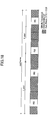
- FIG. 18 illustrates an uplink control channel format according to a fourth embodiment of the present invention.
- reference signals are allocated to the second and sixth block of each slot.
- Control data having an encoded combination of Ack and CQI, an encoded combination of Nack and CQI, or an encoded combination of DTX and CQI are allocated to the first, third through fifth, and seventh block of each slot.
- the control data represent simultaneous encoding of Ack/Nack/DTX + CQI.
- DTX represents data indicating whether Ack/Nack is multiplexed.
- a base station can first determine which format is used for transmission by decoding the first, third through fifth, and seventh blocks of the received reference signals in the same slot. Based on the result of the determination, Ack/Nack and DTX can be demodulated. As a result, significant degrading of throughput due to erroneously determining DTX as Ack/Nack can be prevented.
- FIG. 19 illustrates a block diagram of an uplink control channel transmission part of a user equipment according to the fourth embodiment of the present invention.
- Ack/Nack/DTX of 2 bits and CQI of 4 or 5 bits which total 6 or 7 bits are encoded by an encoding part 71, modulated by a modulating part 72, and supplied to the switching part 13. Further, reference signals of +1 are supplied from the terminal 16 to the switching part 13.
- the switching part 13 sequentially selects and switches the Ack/Nack/DTX + CQI, +1, Ack/Nack/DTX + CQI, Ack/Nack/DTX + CQI, Ack/Nack/DTX + CQI, +1, and Ack/Nack/DTX + CQI illustrated in FIG. 18 in block units.
- the ZC sequence part 18 generates, for example, a ZC sequence of 12 symbols.
- the ZC sequence is converted into parallel form by the S/P part 19 and supplied to the multiplying part 20.
- the multiplying part 20 multiplies the ZC sequence with the signals supplied from the switching part 13 and supplies it to the sub-carrier mapping part 21 in parallel.
- the sub-carrier mapping part 21 maps the signals from the multiplying part 20 to a frequency bandwidth of a sub-carrier of the control channel illustrated in FIG. 5 . Then, because the signals have been processed as signals of a frequency domain until this stage, the signals are converted into signals of time domain by performing inverse Fourier transformation in an IFFT (Inverse Fast Fourier Transform) part 22, are added with CP (Cyclic Prefix) in the CP adding part 23, and are transmitted from the transmitter 24.
- IFFT Inverse Fast Fourier Transform
- FIG. 20 illustrates a block diagram of an uplink control channel receiving part of a base station according to the fourth embodiment of the present invention.
- signals received at the receiver 31 are supplied to the CP removing part 32 by which a CP is removed therefrom. Then, the signals are converted into frequency domain signals in block units by the FFT (Fast Fourier Transform) part 33.
- FFT Fast Fourier Transform
- the sub-carrier de-mapping part 34 performs a sub-carrier de-mapping process and separates control data (Ack/Nack/DTX+CQI) and reference signals according to the format illustrated in FIG. 18 .
- the ZC sequence cancelling part 36 removes the ZC sequence from the control data by multiplying the control data with a complex conjugate sequence. Then, the frequency averaging part 37 obtains the average on the frequency axis from the control data and supplies the average to the phase compensating part 38.
- the ZC cancelling part 41 removes the ZC sequence from the reference signals by multiplying the reference signals with a complex conjugate sequence. Then, the frequency averaging part 42 obtains the average on the frequency axis and supplies the average to the slot averaging part 44.
- the slot averaging part 44 averages the reference signals in a slot with the same phase and supplies the reference signals to the phase compensating part 38.
- the phase compensating part 38 performs phase compensation of the control data according to phase data of the reference signals.
- a channel decoding part 73 decodes and outputs the channel of the control data (Ack/Nack/DTX + CQI).
- the patterns of CQI can be reduced to sixteen by reducing accuracy by 1 bit.
- encoding can be performed in 64 patterns. Because encoding is performed in 64 patterns with 20 bits (in a case of QPSK) per sub-frame (5 blocks), the degrading of received quality of CQI can be prevented. This can be achieved by changing the configuration of the encoding part 71 and the channel decoding part 73.
- the encoding part 11, 14, the modulating part 12, 15, and the switching part 13 are used as a multiplexing part; the switching part 13 is used as a pattern changing part; the format determining part 43 is used as a format detecting part; the SW part 35, 45 and the channel decoding part 46, 47 are used as a separating part; the encoding part 71 and the modulating part 72 are used as an encoding part; the switching part 13 is used as an encoded data multiplexing part; the switching part 35 is used as an encoded data separating part; and the channel decoding part 73 is used as a decoding part.
Landscapes
- Engineering & Computer Science (AREA)
- Signal Processing (AREA)
- Computer Networks & Wireless Communication (AREA)
- Quality & Reliability (AREA)
- Mobile Radio Communication Systems (AREA)
- Digital Transmission Methods That Use Modulated Carrier Waves (AREA)
- Detection And Prevention Of Errors In Transmission (AREA)
- Time-Division Multiplex Systems (AREA)
Abstract
Description
- The embodiments discussed herein are related to a control data communication method and an apparatus for the control data communication method, such as, a control data communication method that multiplexes various independent control data, transmits the data by using a control channel, and separates the control data received from the control channel, and an apparatus for the control data communication method.
- According to a standardization organization 3GPP (3rd Generation Partnership Project), standardization referred to as LTE (Long Term Evolution) is being promoted as a specification of high speed data communication in a mobile communication system. In LTE, there are two kinds of downlink control channels, UL grant and DL Scheduling Information.
- The UL grant is used for permitting transmission of uplink data and designating parameters of the uplink data. When a mobile station (UE: User Equipment) receives the UL grant, the UE performs transmission of uplink data. Further, the DL Scheduling information is used for designating parameters of downlink data to be transmitted immediately after. A mobile station performs reception of downlink data when receiving the DL Scheduling information and transmits Ack or Nack (Ack/Nack) by using an uplink control channel according to check results of CRC (Cyclic Redundancy Check).
- (A) of
FIG. 1 illustrates an example of an uplink control channel format that transmits Ack/Nack. In this example, 1 sub-frame is, for example, 1.0 ms and formed of two slots. Each slot is formed of 7 blocks. RS (reference signal) is a known pilot signal. - Further, in LTE, the uplink control channel is also used for transmitting, for example, CQIs (Channel Quality Indicator). The CQI is an index representing transmission path status of a downlink and is normally transmitted from a base station at a predetermined frequency.
FIG. 1B illustrates an example of an uplink control channel format that transmits CQIs. - In a case where Ack/Nack and CQI are transmitted simultaneously, the Ack/Nack and the CQI are multiplexed and transmitted in the same channel for maintaining single carrier FDMA (SC-FDMA: Single Carrier Frequency Division Multiple Access), which is a characteristic of LTE uplink (see, for example, non-patent
documents -
FIG. 2 illustrates an example of an uplink control channel format according to a related art example. In this example, the Ack/Nack and the CQI are simply time-divisionally multiplexed. -
FIG. 3 illustrates another example of an uplink control channel format according to a related art example. In (A) ofFIG. 3 , Ack is multiplexed for each slot by modulating a reference signal with {1, 1}. In (B) ofFIG. 3 , Nack is multiplexed for each slot by modulating a reference signal with {1, -1}. -
FIG. 4 illustrates another example of an uplink control channel format according to a related art example. InFIG. 4 , Ack/Nack and CQI are encoded together and contained in five blocks of each slot. - Non-Patent Document 1: "3GPP TSG RAN1 #49-bis R1-072706", Orlando, U.S.A, June 25-29, 2007
- Non-Patent Document 2: "3GPP TSG RAN WG1 #49bis R1-072755", Orlando, U.S.A, June 25-29, 2007
- Non-Patent Document 3: "3GPP TSG RAN WG1 Meeting #49bis R1-073003", Orlando, U.S.A, June 25-29, 2007
- Ack/Nack signals are received and determined by a base station (also referred to as "end": evolved Node B). However, in a case where DL Scheduling information could not be received in the downlink, a mobile station does not transmit Ack/Nack (DTX transmission). Therefore, it is necessary for the base station to determine the three values of Ack/Nack/DTX.
- The multiplexing methods of the related art examples illustrated in
FIGS. 2-4 are not formats allowing easy determination of the three values Ack/Nack/DTX. In a case where the base station erroneously determines DTX as Ack, retransmission inLayer 1 cannot be performed and loss of packets occurs. As a result, throughput is significantly degraded. - In view of the above, it is a general object of an embodiment of the present invention to provide a control data communication method and an apparatus for the control data communication method that can easily determine the three values of Ack/Nack/DTX.
- In order to achieve the object, there is provided a control data communication method for multiplexing and transmitting plural mutually independent types of control data by using a control channel and for separating the control data received from the control channel, the control data communication method including: changing and transmitting patterns of reference signals included in the control channel according to a format for multiplexing the control data; detecting the format for multiplexing the transmitted control data according to the pattern of the reference signals included in the control channel; and separating the control data in correspondence with the detected format.
- With the control data communication method, determination of the three values Ack/Nack/DTX can easily be performed, and significant degrading of throughput due to erroneously determining DTX as Ack/Nack can be prevented.
-
-
FIG. 1 is a schematic diagram illustrating an example of an uplink control channel format that transmits Ack/Nack, and CQI according to a related art example; -
FIG. 2 is a schematic diagram illustrating an example of an uplink control channel format according to a related art example; -
FIG. 3 is a schematic diagram illustrating another example of an uplink control channel format according to a related art example; -
FIG. 4 is a schematic diagram illustrating yet another example of an uplink control channel format according to a related art example; -
FIG. 5 is a schematic diagram illustrating a configuration of an LTE uplink channel; -
FIG. 6 is a schematic diagram illustrating an uplink control channel format according to a first embodiment of the present invention; -
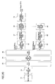
FIG. 7 is a block diagram of an uplink control channel transmitting part of a mobile station according to a first embodiment of the present invention; -
FIG. 8 is a block diagram of an uplink control channel receiving part of a base station according to a first embodiment of the present invention; -
FIG. 9 is a block diagram of an uplink control channel transmitting part of a mobile station according to a related art example; -
FIG. 10 is a block diagram of an uplink control channel receiving part of a base station according to a related art example; -
FIG. 11 is a schematic diagram illustrating a modified example of the uplink control channel format according to the first embodiment of the present invention; -
FIG. 12 is a schematic diagram illustrating an uplink control channel format according to a second embodiment of the present invention; -
FIG. 13 is a block diagram of an uplink control channel transmitting part of a mobile station according to the second embodiment of the present invention; -
FIG. 14 is a block diagram of an uplink control channel receiving part of a base station according to the second embodiment of the present invention; -
FIG. 15 is a schematic diagram of an uplink control channel format according to a third embodiment of the present invention; -
FIG. 16 is a block diagram of an uplink control channel transmitting part of a mobile station according to the third embodiment of the present invention; -
FIG. 17 is a block diagram of an uplink control channel receiving part of a base station according to the third embodiment of the present invention; -
FIG. 18 is a schematic diagram illustrating an uplink control channel format according to a fourth embodiment of the present invention; -
FIG. 19 is a block diagram of an uplink control channel transmitting part of a mobile station according to the fourth embodiment of the present invention; and -
FIG. 20 is a block diagram of an uplink control channel receiving part of a base station according to the fourth embodiment of the present invention. -
- 11, 14, 51, 71
- encoding part
- 12, 15, 52, 72
- modulating part
- 13
- switching part
- 18
- S/P part
- 20
- multiplying part
- 21
- sub-carrier mapping part
- 22
- IFFT part
- 23
- CP adding part
- 24
- transmitter
- 31
- receiver
- 32
- CP removing part
- 33
- FFT part
- 34
- sub-carrier mapping part
- 35, 45
- SW part
- 36, 41
- ZC sequence cancelling part
- 37, 42
- frequency averaging part
- 38
- phase compensating part
- 43
- format determining part
- 44
- slot averaging part
- 46, 47, 53, 54, 73
- channel decoding part
- 62
- selecting part
- Next, embodiments of the present invention are described with reference to the drawings.
- Single carrier FDMA (SC-FDMA) is used in an LTE uplink. With the SC-FDMA, transmission frequency bandwidth may change for each sub-frame; it is, however, limited to using a single frequency bandwidth for performing a single transmission. Therefore, for example, data signals and control data cannot be simultaneously transmitted with different frequency bandwidths. Accordingly, with the LTE, in a case where data signals are to be transmitted simultaneously with the transmission of control data, the control data are multiplexed in the same bandwidth as the data signals. On the other hand, in a case of not simultaneously transmitting the control data and data signals, the control data are transmitted with a bandwidth different from the bandwidth normally used for transmitting data signals (as described below).
-
FIG. 5 illustrates a configuration of a channel for LTE uplink. In the drawing, the horizontal axis represents a time axis and the vertical axis represents a frequency axis. The control channel in an LTE uplink is assigned to, for example, both sides of a system bandwidth. In the same manner as the data channel, control data are transmitted in the control channel in units of subframes (1.0 ms). However, in order to obtain frequency diversity gain, frequency hopping is performed for each slot (0.5 ms). - As illustrated in
FIG. 5 , different bandwidths are assigned to the Ack/Nack and CQI. The user equipment measures reception quality of a downlink, quantizes the quality as CQI, and periodically transmits the CQI at predetermined fixed periods. - In a case where the user equipment receives a downlink signal, the user equipment transmits Ack/Nack according to the result of a CRC check after decoding the downlink signal. However, the timing for transmitting the Ack/Nack is not predetermined. Accordingly, in some case, it may be necessary to transmit Ack/Nack at the same time of transmitting CQI. In this case, CQI and Ack/Nack are multiplexed and transmitted with the bandwidth used for transmitting CQI.
-
FIG. 6 illustrates an uplink control channel format according to a first embodiment of the present invention. In (A) and (B) ofFIG. 6 , one sub-frame consists of, for example, two slots of 1.0 ms, in which each slot consists of seven blocks. (A) ofFIG. 6 illustrates a case where there is only CQI (i.e. a case where DTX is multiplexed with CQI). In this case, the reference signals in two of the blocks of the same slot are modulated with the same phase (i.e. modulated with {1, 1}). - (B) of
FIG. 6 illustrates a case where Ack/Nack and CQI are time-division multiplexed. In this case, the reference signals in two of the blocks of the same slot are modulated with a reversed phase (i.e. modulated with {1, -1}). It is to be noted that CQI and Ack/Nack are allocated to the slots on the left and right. - Accordingly, a base station can first determine which format is used for transmission by determining the phase of the received reference signals in the same slot. Based on the result of the determination, Ack/Nack and DTX can be demodulated. As a result, significant degrading of throughput due to erroneously determining DTX as Ack/Nack can be prevented.
-
FIG. 7 illustrates a block diagram of an uplink control channel transmission part of a user equipment according to a first embodiment of the present invention. InFIG. 7 , for example, Ack/Nack of 1 or 2 bits is repetitively encoded in anencoding part 11, modulated in a modulatingpart 12, and supplied to a switchingpart 13. Meanwhile, for example, CQI of 4 or 5 bits is convolutionally encoded in anencoding part 14, modulated in a modulatingpart 15, and supplied to the switchingpart 13. - The switching
part 13 sequentially selects and switches the CQI, +1, CQI, CQI, +1, and CQI illustrated in (A) ofFIG. 6 in block units. Further, the CQI, +1, Ack/Nack, CQI, Ack/Nack, -1, CQI illustrated in (B) ofFIG. 6 are sequentially selected and switched and supplied to a multiplyingpart 20 in block units. - A
ZC sequence part 18 generates, for example, a ZC sequence of 12 symbols. The ZC sequence is converted into parallel form by a S/P (serial/parallel converting)part 19 and supplied to the multiplyingpart 20. The multiplyingpart 20 multiplies the ZC sequence with the signals supplied from the switchingpart 13 and supplies it to asub-carrier mapping part 21 in parallel. - The
sub-carrier mapping part 21 maps the signals from the multiplyingpart 20 to a frequency bandwidth of a sub-carrier of the control channel illustrated inFIG. 5 . Then, because the signals have been processed as signals of a frequency domain until this stage, the signals are converted into signals of time domain by performing inverse Fourier transformation in an IFFT (Inverse Fast Fourier Transform)part 22, are added with CP (Cyclic Prefix) in aCP adding part 23, and are transmitted from a transmittingpart 24. -
FIG. 8 illustrates a block diagram of an uplink control channel receiving part of a base station according to a first embodiment of the present invention. InFIG. 8 , signals received at areceiver 31 are supplied to aCP removing part 32 by which a CP (Cyclic Prefix) is removed therefrom. Then, the signals are converted into frequency domain signals in block units by a FFT (Fast Fourier Transform)part 33. - Then, the sub-carrier
de-mapping part 34 performs a sub-carrier de-mapping process and separates control data (Ack/Nack, CQI) and reference signals according to the formats illustrated in (A) and (B) ofFIG. 6 . - A ZC
sequence cancelling part 36 removes the ZC sequence from the control data by multiplying the control data with a complex conjugate sequence. Then, afrequency averaging part 37 obtains the average on the frequency axis from the control data and supplies the average to aphase compensating part 38. - A
ZC cancelling part 41 removes the ZC sequence from the reference signals by multiplying the reference signals with a complex conjugate sequence. Then, afrequency averaging part 42 obtains the average on the frequency axis and supplies the average to aformat determining part 43 and aslot averaging part 44. - The
format determining part 43 obtains correlation values of the averaged reference signal for a pattern {+1, +1} and for a pattern {+1, -1} and determines that the one having greater correlation value is the pattern of the actually transmitted reference signal, that is, the transmitted format. In other words, theformat determining part 43 determines whether the transmitted format is a format including only CQI (multiplexed with DTX) as illustrated in (A) ofFIG. 6 or a format including Ack/Nack multiplexed with CQI as illustrated in (B) ofFIG. 6 depending on whether the reference signals in the slot have the same phase or the opposite phase. Theformat determining part 43 supplies the determination result to aslot averaging part 44, aSW part 45, and thechannel decoding parts - Based on the result of the format determination, the
slot averaging part 44 averages the reference signals in a slot either in a case where the reference signals in a slot have the same phase (a case where the pattern is {+1, +1}) or the opposite phase (a case where the pattern is {+1, - 1}). Thephase compensating part 38 performs phase compensation of the control data according to phase data of the reference signals. - Then, the
SW part 45 separates the control data into Ack/Nack and CQI in accordance with the format. Thechannel decoding part 46 decodes the channel of the Ack/Nack and outputs the Ack/Nack. Thechannel decoding part 47 decodes the channel of the CQI and outputs the CQI. - In a case where the number of mapped symbols of the CQI decreases, there is a risk of degrading of reception quality of CQI. Therefore, in a case of transmitting Ack/Nack and CQI, the accuracy of CQI may be reduced.
- For example, in a case of transmitting only CQI (format illustrated in (A) of
FIG. 6 ) where there are 32 patterns of CQI, the encoding rate is 0.25 when encoding 5 bits representing the 32 patterns with 20 bits per sub-frame (5 blocks) (in a case of QPSK). - In a case of transmitting Ack/Nack + CQI (format illustrated in (B) of
FIG. 6 ) where there are 32 patterns of CQI, the number of bits assigned for transmission of CQI is 12 bits per sub-frame (3 blocks). Therefore, the encoding rate is 0.42. In this case, by reducing the accuracy of CQI to 4 bits (16 patterns), the encoding rate can be 0.33. Thus, throughput can be prevented from degrading. - For comparison,
Fig. 9 illustrates a block configuration of an uplink control channel transmitting part in a case where a format according to a related art example ofFIG. 2 is used, andFIG. 10 illustrates a block configuration of an uplink control channel receiving part in a case where a format according to a related art example ofFIG. 2 is used. InFIG. 9 andFIG. 10 , like components are denoted with like reference numerals as those ofFIG. 7 andFIG. 8 . InFIG. 9 , only +1 is supplied from a terminal 16 to the switchingpart 13. That is, reference signals are supplied where Ack/Nack is multiplexed or where DTX is multiplexed. The switchingpart 13 ofFIG. 7 supplies different reference signals according to a case where Ack/Nack is multiplexed and where DTX is multiplexed. InFIG. 10 , there is noformat determining part 43. - In single carrier transmission, in a case where frequency is equalized at the receiving side, reference signals are preferred to have constant amplitude in the frequency region (i.e. the autocorrelation of a given periodic time shift is 0) in order to improve the accuracy of frequency estimation in the frequency region. On the other hand, from the standpoint of PAPR (Peak-to-Average Power Ratio), it is preferable that the reference signals have constant amplitude in a time region.
- As an exemplary sequence for realizing these characteristics, a ZC (Zadoff-Chu) sequence is proposed. The Formula thereof is illustrated below. Here, "k" represents a symbol number and "n" represents an index in a time direction. If the integers of "k" and "L" are both primary, the sequence length is "L".

-
FIG. 11 illustrates a modified example of an uplink control channel format according to the first embodiment of the present invention. (A) ofFIG. 11 illustrates a case where there is only CQI (i.e. a case where DTX is multiplexed with CQI). In this case, the reference signals in two of the blocks of the same slot are modulated with the same phase (i.e. modulated with {1, 1}). This is the same as (A) ofFIG. 6 . - (B) of
FIG. 11 illustrates a case where Ack/Nack and CQI are time-division multiplexed. In this case, the reference signals in two of the blocks of the same slot are modulated with a reversed phase (i.e. modulated with {1, -1}). CQI is allocated to the slot of the left side and Ack/Nack is allocated to the slot of the right side. - This is merely one example illustrating symbol positions of Ack/Nack. In this embodiment of the present invention, the positions of Ack/Nack and other symbols are not limited to the example.
-
FIG. 12 illustrates an uplink control channel format according to a second embodiment of the present invention. (A) ofFIG. 12 illustrates a case where there is only CQI (i.e. a case where DTX is multiplexed with CQI). In this case, the reference signals in two of the blocks of the same slot are modulated with the same phase (i.e. modulated with {1, 1}). This is the same as (A) ofFIG. 6 . - (B) of
FIG. 12 illustrates a case where Ack and CQI or Nack and CQI are combined and encoded (simultaneous encoding of Ack/Nack and CQI). In this case, the reference signals in two blocks of the same slot are modulated with a reversed phase (i.e. modulated with {1, -1}). - Therefore, a base station can first determine which format is used for transmission by determining the phase of received reference signals in the same slot. Based on the result of the determination, Ack/Nack and DTX can be demodulated. As a result, significant degrading of throughput due to erroneously determining DTX as Ack/Nack can be prevented.
-
FIG. 13 illustrates a block diagram of an uplink control channel transmitting part of a user equipment according to a second embodiment of the present invention. InFIG. 13 , for example, Ack/Nack of 1 or 2 bits and CQI of 5 bits which total 6 or 7 bits (Ack/Nack + CQI) are encoded by anencoding part 51, modulated by a modulatingpart 52, and supplied to the switchingpart 13. - The switching
part 13 sequentially selects and switches the CQI, +1, CQI, CQI, CQI, +1, and CQI illustrated in (A) ofFIG. 12 in block units. Further, the Ack/Nack + CQI, +1, Ack/Nack + CQI, Ack/Nack + CQI, Ack/Nack + CQI, -1, and Ack/Nack + CQI illustrated in (B) ofFIG. 12 are sequentially selected and switched and supplied to the multiplyingpart 20 in block units. - The
ZC sequence part 18 generates, for example, a ZC sequence of 12 symbols. The ZC sequence is converted into parallel form by the S/P part 19 and supplied to the multiplyingpart 20. The multiplyingpart 20 multiplies the ZC sequence with the signals supplied from the switchingpart 13 and supplies it to thesub-carrier mapping part 21 in parallel. - The
sub-carrier mapping part 21 maps the signals from the multiplyingpart 20 to a frequency bandwidth of a sub-carrier of the control channel illustrated inFIG. 5 . Then, because the signals have been processed as signals of a frequency domain until this stage, the signals are converted into signals of time domain by performing inverse Fourier transformation in an IFFT (Inverse Fast Fourier Transform)part 22, are added with CP (Cyclic Prefix) in theCP adding part 23, and are transmitted from thetransmitter 24. -
FIG. 14 illustrates a block diagram of an uplink control channel receiving part of a base station according to the second embodiment of the present invention. InFIG. 14 , signals received at thereceiver 31 are supplied to theCP removing part 32 by which a CP is removed therefrom. Then, the signals are converted into frequency domain signals in block units by the FFT (Fast Fourier Transform)part 33. - Then, the sub-carrier
de-mapping part 34 performs a sub-carrier de-mapping process and separates control data (Ack/Nack + CQI, CQI) and reference signals according to the formats illustrated in (A) and (B) ofFIG. 12 . - The ZC
sequence cancelling part 36 removes the ZC sequence from the control data by multiplying the control data with a complex conjugate sequence. Then, thefrequency averaging part 37 obtains the average on the frequency axis from the control data and supplies the average to thephase compensating part 38. - The
ZC cancelling part 41 removes the ZC sequence from the reference signals by multiplying the reference signals with a complex conjugate sequence. Then, thefrequency averaging part 42 obtains the average on the frequency axis and supplies the average to theformat determining part 43 and theslot averaging part 44. - The
format determining part 43 obtains correlation values of the averaged reference signal for a pattern {+1, +1} and for a pattern {+1, -1} and determines that the one having a greater correlation value is the pattern of the actually transmitted reference signal, that is, the transmitted format. In other words, theformat determining part 43 determines whether the transmitted format is a format including only CQI (multiplexed with DTX) as illustrated in (A) ofFIG. 12 or a format including Ack/Nack multiplexed with CQI as illustrated in (B) ofFIG. 12 depending on whether the reference signals in a slot have the same phase or the opposite phase. Theformat determining part 43 supplies the determination result to theslot averaging part 44 and theSW part 45. Further, in a case where the format includes only CQI, DTX is output. - Based on the result of the format determination, the
slot averaging part 44 averages the reference signals in a slot either in a case where the reference signals in a slot have the same phase (a case where the pattern is {+1, +1}) or the opposite phase (a case where the pattern is {+1, - 1}). Thephase compensating part 38 performs phase compensation of the control data according to phase data of the reference signals. - Then, the
SW part 45 separates the control data into Ack/Nack + CQI and CQI in accordance with the format. Thechannel decoding part 46 decodes the channel of the Ack/Nack and outputs the Ack/Nack. Thechannel decoding part 47 decodes the channel of the CQI and outputs the CQI. -
FIG. 15 illustrates an uplink control channel format according to a third embodiment of the present invention. (A) ofFIG. 15 illustrates a format of Ack + CQI. In this case, the phase of the reference signal in the second block of the same slot is a criterion (phase 0), and the reference signal of the sixth block is modulated with a phase of 2π/3 (i.e. modulated with {1, exp[2π/3]}). - (B) of
FIG. 15 illustrates a format of Nack + CQI. In this case, the phase of the reference signal in the second block of the same slot is a criterion (phase 0), and the reference signal of the sixth block is modulated with a phase of 4π/3 (i.e. modulated with {1, exp[4π/3]}). - (C) of
FIG. 15 illustrates of a format of DTX + CQI. In this case, the phase of the reference signals in the second and sixth blocks of the same slot is a criterion (phase 0), and the reference signals are modulated (i.e. modulated with {1, 1}). - Accordingly, a base station can first determine which format is used for transmission by determining the phase of the received reference signals in the same slot. Based on the result of the determination, Ack/Nack and DTX can be demodulated. As a result, significant degrading of throughput due to erroneously determining DTX as Ack/Nack can be prevented.
-
FIG. 16 illustrates a block diagram of an uplink control channel transmission part of a user equipment according to the third embodiment of the present invention. InFIG. 16 , for example, CQI of 5 bits is repetitively encoded in theencoding part 14, modulated in the modulatingpart 15, and supplied to the switchingpart 13. - Three types of
reference signals 1, exp[2 π/3], exp[4π/3], which are to be supplied to the switchingpart 13, are supplied to a selectingpart 62. DTX/Ack/Nack (e.g., 2 bits) from a terminal 61 are supplied to the switchingpart 13. The selectingpart 62 selects a reference signal of 1 in the second block of a slot. In addition, in a case of DTX, a reference signal of 1 is selected in the sixth block of a slot. In a case of Ack, a reference signal of exp[2π/3] is selected. In a case of Nack/ a reference signal of exp[4π/3] is selected. The selected reference signals are supplied to the switchingpart 13. - In a case of Ack, the switching
part 13 sequentially selects and switches the CQI, exp[2π /3], CQI, CQI, CQI, exp[2π/3], and CQI illustrated in (A) ofFIG. 15 to the multiplyingpart 20 in block units. Further, in a case of Nack, the CQI, exp[4π/3], CQI, CQI, CQI, exp[4π/3], and CQI illustrated in (B) ofFIG. 15 are sequentially selected and switched and supplied to the multiplyingpart 20 in block units. - The
ZC sequence part 18 generates, for example, a ZC sequence of 12 symbols. The ZC sequence is converted into parallel form by the S/P part 19 and supplied to the multiplyingpart 20. The multiplyingpart 20 multiplies the ZC sequence with the signals supplied from the switchingpart 13 and supplies it to thesub-carrier mapping part 21 in parallel. - The
sub-carrier mapping part 21 maps the signals from the multiplyingpart 20 to a frequency bandwidth of a sub-carrier of the control channel illustrated inFIG. 5 . Then, because the signals have been processed as signals of a frequency domain until this stage, the signals are converted into signals of time domain by performing inverse Fourier transformation in an IFFT (Inverse Fast Fourier Transform)part 22, are added with CP (Cyclic Prefix) in theCP adding part 23, and are transmitted from thetransmitter 24. -
FIG. 17 illustrates a block diagram of an uplink control channel receiving part of a base station according to the third embodiment of the present invention. InFIG. 17 , signals received at thereceiver 31 are supplied to theCP removing part 32 by which a CP is removed therefrom. Then, the signals are converted into frequency domain signals in block units by the FFT (Fast Fourier Transform)part 33. - Then, the sub-carrier
de-mapping part 34 performs a sub-carrier de-mapping process and separates control data (CQI) and reference signals according to the formats illustrated in (A), (B), and (C) ofFIG. 15 . - The ZC
sequence cancelling part 36 removes the ZC sequence from the control data by multiplying the control data with a complex conjugate sequence. Then, thefrequency averaging part 37 obtains the average on the frequency axis from the control data and supplies the average to thephase compensating part 38. - The
ZC cancelling part 41 removes the ZC sequence from the reference signals by multiplying the reference signals with a complex conjugate sequence. Then, thefrequency averaging part 42 obtains the average on the frequency axis and supplies the average to theformat determining part 63 and theslot averaging part 44. - The
format determining part 63 obtains correlation values of the averaged reference signal for a pattern {1, 1}, for a pattern {1, exp[2π/3]}, and for a pattern {exp[4π/3]} and determines that the one having greatest correlation value is the pattern of the actually transmitted reference signal, that is, the transmitted format. In other words, theformat determining part 43 determines whether the transmitted format is a format including Ack + CQI as illustrated in (A) ofFIG. 15 , a format including Nack + CQI as illustrated in (B) ofFIG. 15 , or a format including DTX + CQI depending on whether the reference signals in a slot have the same phase or the opposite phase. Theformat determining part 63 supplies the determination result to theslot averaging part 44 along with outputting it to the outside. - Based on the result of the format determination, the
slot averaging part 44 averages the reference signals according to the result of the format determination after making the phase of the reference signals in a slot the same (e.g., phase of 0) and supplies the reference signals to thephase compensating part 38. Thephase compensating part 38 performs phase compensation of the control data according to phase data of the reference signals. Then, regardless of the type of format illustrated in (A), (B), or (C) ofFIG. 15 , thechannel decoding part 54 decodes and outputs the channel of the CQI of the control data. - Although the above-described embodiment describes the reference signals having three patterns {1, 1}, {1, exp(2π/3)}, and {1, exp(4π /3)}, the reference signals may have four patterns {1, 1}, {1, exp(π/4)}, {1, exp(π/2)}, and {1, exp(3π/4)}.
-
FIG. 18 illustrates an uplink control channel format according to a fourth embodiment of the present invention. Here, reference signals are allocated to the second and sixth block of each slot. Control data having an encoded combination of Ack and CQI, an encoded combination of Nack and CQI, or an encoded combination of DTX and CQI are allocated to the first, third through fifth, and seventh block of each slot. It is to be noted that the control data represent simultaneous encoding of Ack/Nack/DTX + CQI. Further, DTX represents data indicating whether Ack/Nack is multiplexed. - Accordingly, a base station can first determine which format is used for transmission by decoding the first, third through fifth, and seventh blocks of the received reference signals in the same slot. Based on the result of the determination, Ack/Nack and DTX can be demodulated. As a result, significant degrading of throughput due to erroneously determining DTX as Ack/Nack can be prevented.
-
FIG. 19 illustrates a block diagram of an uplink control channel transmission part of a user equipment according to the fourth embodiment of the present invention. InFIG. 19 , for example, Ack/Nack/DTX of 2 bits and CQI of 4 or 5 bits which total 6 or 7 bits (Ack/Nack/DTX + CQI) are encoded by anencoding part 71, modulated by a modulatingpart 72, and supplied to the switchingpart 13. Further, reference signals of +1 are supplied from the terminal 16 to the switchingpart 13. - The switching
part 13 sequentially selects and switches the Ack/Nack/DTX + CQI, +1, Ack/Nack/DTX + CQI, Ack/Nack/DTX + CQI, Ack/Nack/DTX + CQI, +1, and Ack/Nack/DTX + CQI illustrated inFIG. 18 in block units. - The
ZC sequence part 18 generates, for example, a ZC sequence of 12 symbols. The ZC sequence is converted into parallel form by the S/P part 19 and supplied to the multiplyingpart 20. The multiplyingpart 20 multiplies the ZC sequence with the signals supplied from the switchingpart 13 and supplies it to thesub-carrier mapping part 21 in parallel. - The
sub-carrier mapping part 21 maps the signals from the multiplyingpart 20 to a frequency bandwidth of a sub-carrier of the control channel illustrated inFIG. 5 . Then, because the signals have been processed as signals of a frequency domain until this stage, the signals are converted into signals of time domain by performing inverse Fourier transformation in an IFFT (Inverse Fast Fourier Transform)part 22, are added with CP (Cyclic Prefix) in theCP adding part 23, and are transmitted from thetransmitter 24. -
FIG. 20 illustrates a block diagram of an uplink control channel receiving part of a base station according to the fourth embodiment of the present invention. InFIG. 20 , signals received at thereceiver 31 are supplied to theCP removing part 32 by which a CP is removed therefrom. Then, the signals are converted into frequency domain signals in block units by the FFT (Fast Fourier Transform)part 33. - Then, the sub-carrier
de-mapping part 34 performs a sub-carrier de-mapping process and separates control data (Ack/Nack/DTX+CQI) and reference signals according to the format illustrated inFIG. 18 . - The ZC
sequence cancelling part 36 removes the ZC sequence from the control data by multiplying the control data with a complex conjugate sequence. Then, thefrequency averaging part 37 obtains the average on the frequency axis from the control data and supplies the average to thephase compensating part 38. - The
ZC cancelling part 41 removes the ZC sequence from the reference signals by multiplying the reference signals with a complex conjugate sequence. Then, thefrequency averaging part 42 obtains the average on the frequency axis and supplies the average to theslot averaging part 44. - The
slot averaging part 44 averages the reference signals in a slot with the same phase and supplies the reference signals to thephase compensating part 38. Thephase compensating part 38 performs phase compensation of the control data according to phase data of the reference signals. Then, achannel decoding part 73 decodes and outputs the channel of the control data (Ack/Nack/DTX + CQI). - In a case where CQI is 5 bits (32 patterns), encoding of a total of 96 patterns is performed since each of Ack + CQI, Nack + CQI, DTX + CQI would have 32 patterns. Thus, encoding is performed in 96 patterns (7 bits) with 20 bits (in a case of QPSK) per sub-frame (5 blocks).
- Accordingly, in a case of combining with Ack/Nack, the patterns of CQI can be reduced to sixteen by reducing accuracy by 1 bit. In this case, because Ack + CQI has 16 patterns, Nack + CQI has 16 patterns, and DTX + CQI has 32 patterns, encoding can be performed in 64 patterns. Because encoding is performed in 64 patterns with 20 bits (in a case of QPSK) per sub-frame (5 blocks), the degrading of received quality of CQI can be prevented. This can be achieved by changing the configuration of the
encoding part 71 and thechannel decoding part 73. - In the above-described embodiments, the
encoding part part part 13 are used as a multiplexing part; the switchingpart 13 is used as a pattern changing part; theformat determining part 43 is used as a format detecting part; theSW part channel decoding part encoding part 71 and the modulatingpart 72 are used as an encoding part; the switchingpart 13 is used as an encoded data multiplexing part; the switchingpart 35 is used as an encoded data separating part; and thechannel decoding part 73 is used as a decoding part.
Claims (20)
- A control data communication method for multiplexing and transmitting a plurality of mutually independent types of control data by using a control channel and for separating the control data received from the control channel, the control data communication method characterized by comprising:changing and transmitting patterns of reference signals included in the control channel according to a format for multiplexing the control data;detecting the format for multiplexing the transmitted control data according to the pattern of the reference signals included in the control channel; andseparating the control data in correspondence with the detected format.
- The control data communication method as claimed in claim 1, characterized in that the changing of the patterns of reference signals is based on a phase of a plurality of the reference signals included in each of the slots of the control channel.
- The control data communication method as claimed in claim 2, characterized in that the phase of the plural reference signals included in each of the slots is plural.
- The control data communication method as claimed in claim 1, characterized in that multiplexed plural types of control data are allocated to a same slot of the control channel.
- The control data communication method as claimed in claim 1, characterized in that multiplexed plural types of control data are allocated to different slots of the control channel.
- The control data communication method as claimed in claim 1, characterized in that the plural types of control data to be multiplexed are combined and encoded, and the plural types of control data are obtained by decoding and separating encoded data received from the control channel.
- A control data communication method for multiplexing and transmitting a plurality of mutually independent types of control data by using a control channel and for separating the control data received from the control channel, the control data communication method characterized by comprising:combining and encoding the plural types of control data and multiplex indication data of a given control data; andobtaining the plural types of control data and the multiplex indication data of the given control data by separating and decoding encoded data received from the control channel.
- The control data communication method as claimed in claim 1 or claim 7, characterized in that at least a single accuracy of control data to be multiplexed is reduced in correspondence with an increase in the types of control data to be multiplexed.
- A transmitting apparatus included in a control data communication system for multiplexing and transmitting a plurality of mutually independent types of control data by using a control channel and for separating the control data received from the control channel, the transmitting apparatus characterized by comprising:a multiplexing part configured to multiplex the plural mutually independent types of control data; anda pattern changing part configured to change a pattern of reference signals included in the control channel according to a format for multiplexing the control data.
- A receiving apparatus included in a control data communication system for multiplexing and transmitting a plurality of mutually independent types of control data by using a control channel and for separating the control data received from the control channel, the receiving apparatus characterized by comprising:a format detecting part configured to detect a format of transmitted multiplexed control data according to a pattern of received reference signals included in the control channel; anda separating part configured to separate the control data according to the control channel.
- The transmitting apparatus as claimed in claim 9, characterized in that the pattern changing part is configured to change the pattern of the reference signals by making a phase of the plural reference signals included in each of the slots of the control channel.
- The receiving apparatus as claimed in claim 10, characterized in that the format detecting part is configured to detect the format for multiplexing the transmitted control data according to a phase of the plural reference signals included in each of the slots of the control channel.
- The transmitting apparatus as claimed in claim 12, characterized in that the pattern changing part makes the phase of the plural reference signals included in each of the slots plural.
- The transmitting apparatus as claimed in claim 9, characterized in that the multiplexing part is configured to reduce at least a single accuracy of control data to be multiplexed in correspondence with an increase in the types of control data to be multiplexed.
- The transmitting apparatus as claimed in claim 9, characterized in that the multiplexing part is configured to allocate the multiplexed plural types of control data to a same slot of the control channel.
- The transmitting apparatus as claimed in claim 10, characterized in that the multiplexing part is configured to allocate the multiplexed plural types of control data to different slots of the control channel.
- The transmitting apparatus as claimed in claim 9, characterized in that the multiplexing part is configured to combine and encode the plural types of control data to be multiplexed.
- The receiving apparatus as claimed in claim 10 characterized in that the separating part is configured to obtain the plural types of control data by decoding and separating encoded data received from the control channel.
- A transmitting apparatus included in a control data communication system for multiplexing and transmitting a plurality of mutually independent types of control data by using a control channel and for separating the control data received from the control channel, the transmitting apparatus characterized by comprising:an encoding part configured to combine and encode the plural types of control data and multiplex indication data of a given control data; andan encoded data multiplexing part configured to multiplex the encoded data obtained from the encoding part.
- A receiving apparatus included in a control data communication system for multiplexing and transmitting a plurality of mutually independent types of control data by using a control channel and for separating the control data received from the control channel, the receiving apparatus characterized by comprising:an encoded data separating part configured to separate combined and encoded data of the plural types of control data and multiplex indication data of a given control data received from the control channel; anda decoding part configured to obtain the plural types of control data and multiplex indication data of the given control data by decoding the encoded data obtained from the encoded data separating part.
Applications Claiming Priority (1)
| Application Number | Priority Date | Filing Date | Title |
|---|---|---|---|
| PCT/JP2007/067026 WO2009028095A1 (en) | 2007-08-31 | 2007-08-31 | Control information communication method and its device |
Publications (2)
| Publication Number | Publication Date |
|---|---|
| EP2187546A1 true EP2187546A1 (en) | 2010-05-19 |
| EP2187546A4 EP2187546A4 (en) | 2012-12-12 |
Family
ID=40386839
Family Applications (1)
| Application Number | Title | Priority Date | Filing Date |
|---|---|---|---|
| EP07806499A Withdrawn EP2187546A4 (en) | 2007-08-31 | 2007-08-31 | METHOD OF COMMUNICATING CONTROL INFORMATION AND DEVICE THEREOF |
Country Status (4)
| Country | Link |
|---|---|
| US (1) | US20100172373A1 (en) |
| EP (1) | EP2187546A4 (en) |
| JP (1) | JPWO2009028095A1 (en) |
| WO (1) | WO2009028095A1 (en) |
Cited By (2)
| Publication number | Priority date | Publication date | Assignee | Title |
|---|---|---|---|---|
| EP2166690A3 (en) * | 2008-09-18 | 2014-02-26 | Fujitsu Limited | Communication apparatus, base station apparatus and communication method |
| US9131507B2 (en) | 2010-05-25 | 2015-09-08 | China Academy Of Telecommunications Technology | Method and apparatus for receiving signals |
Families Citing this family (9)
| Publication number | Priority date | Publication date | Assignee | Title |
|---|---|---|---|---|
| US20090141690A1 (en) * | 2007-10-01 | 2009-06-04 | Qualcomm Incorporated | Method and apparatus for uplink control signaling |
| US8559946B2 (en) * | 2008-02-08 | 2013-10-15 | Qualcomm Incorporated | Discontinuous transmission signaling over an uplink control channel |
| WO2010137318A1 (en) * | 2009-05-26 | 2010-12-02 | 京セラ株式会社 | Wireless communication terminal, base station, wireless communication method and wireless communication system |
| EP2469784A4 (en) * | 2009-08-17 | 2016-01-13 | Lg Electronics Inc | METHOD AND APPARATUS FOR ALLOCATING AN UPLINK CARRIER FOR TRANSMITTING UPLINK CONTROL INFORMATION IN A WIRELESS COMMUNICATION SYSTEM |
| RU2548903C2 (en) | 2010-02-10 | 2015-04-20 | Панасоник Интеллекчуал Проперти Корпорэйшн оф Америка | Terminal and communication method thereof |
| JP5296183B2 (en) * | 2011-12-14 | 2013-09-25 | 日本電信電話株式会社 | Receiving apparatus and receiving method |
| JP5296182B2 (en) * | 2011-12-14 | 2013-09-25 | 日本電信電話株式会社 | Receiving apparatus and receiving method |
| US8787225B2 (en) * | 2012-07-11 | 2014-07-22 | Blackberry Limited | Phase-rotated reference signals for multiple antennas |
| US8792399B2 (en) * | 2012-07-11 | 2014-07-29 | Blackberry Limited | Phase-rotated reference signals for multiple antennas |
Family Cites Families (4)
| Publication number | Priority date | Publication date | Assignee | Title |
|---|---|---|---|---|
| EP1564923A1 (en) * | 2004-02-12 | 2005-08-17 | Samsung Electronics Co., Ltd. | Apparatus and method for transmitting control information in a mobile communication system |
| BRPI0720512A2 (en) * | 2006-10-04 | 2014-11-18 | Qualcomm Inc | UPLINK ACK TRANSMISSION TO SDMA IN A WIRELESS COMMUNICATION SYSTEM |
| KR100956494B1 (en) * | 2007-06-14 | 2010-05-07 | 엘지전자 주식회사 | Control signal transmission method |
| EP2176965B1 (en) * | 2007-07-16 | 2018-09-05 | Samsung Electronics Co., Ltd. | Apparatus and method for transmitting of channel quality indicator and acknowledgement signals in sc-fdma communication systems |
-
2007
- 2007-08-31 WO PCT/JP2007/067026 patent/WO2009028095A1/en not_active Ceased
- 2007-08-31 EP EP07806499A patent/EP2187546A4/en not_active Withdrawn
- 2007-08-31 JP JP2009529944A patent/JPWO2009028095A1/en active Pending
-
2010
- 2010-02-22 US US12/709,844 patent/US20100172373A1/en not_active Abandoned
Cited By (2)
| Publication number | Priority date | Publication date | Assignee | Title |
|---|---|---|---|---|
| EP2166690A3 (en) * | 2008-09-18 | 2014-02-26 | Fujitsu Limited | Communication apparatus, base station apparatus and communication method |
| US9131507B2 (en) | 2010-05-25 | 2015-09-08 | China Academy Of Telecommunications Technology | Method and apparatus for receiving signals |
Also Published As
| Publication number | Publication date |
|---|---|
| EP2187546A4 (en) | 2012-12-12 |
| WO2009028095A1 (en) | 2009-03-05 |
| JPWO2009028095A1 (en) | 2010-11-25 |
| US20100172373A1 (en) | 2010-07-08 |
Similar Documents
| Publication | Publication Date | Title |
|---|---|---|
| EP2187546A1 (en) | Control information communication method and its device | |
| US10993227B2 (en) | Apparatus and method for allocating resource in a mobile communication system | |
| US8797946B2 (en) | User device, base station, and method | |
| KR101350623B1 (en) | Method of Transmitting Scheduling Reference Signal | |
| US8325593B2 (en) | Mobile communication system, base station, user device, and method | |
| US8428019B2 (en) | Base station | |
| EP2176964B1 (en) | Apparatus and method for transmitting uplink control channels in a wireless communication system | |
| AU2007246533B2 (en) | Transmission apparatus and reception apparatus | |
| EP1806867A2 (en) | Method and apparatus for time multiplexing uplink data and uplink signaling information in a SC-FDMA system | |
| US8331301B2 (en) | Communication control method, mobile station and base station | |
| EP3537638B1 (en) | Encoding ratio setting method and radio communication device | |
| KR101414962B1 (en) | A method for transmitting and receiving an uplink channel sounding reference signal in a wireless communication system | |
| KR100918729B1 (en) | Method and apparatus for time multiplexing packet data and uplink control information in single carrier frequency division multiple access system | |
| JP5338893B2 (en) | Control information communication method and apparatus | |
| HK1219581A1 (en) | Mobile station and base station apparatuses and methods for sending and receiving channel quality information |
Legal Events
| Date | Code | Title | Description |
|---|---|---|---|
| PUAI | Public reference made under article 153(3) epc to a published international application that has entered the european phase |
Free format text: ORIGINAL CODE: 0009012 |
|
| 17P | Request for examination filed |
Effective date: 20100315 |
|
| AK | Designated contracting states |
Kind code of ref document: A1 Designated state(s): AT BE BG CH CY CZ DE DK EE ES FI FR GB GR HU IE IS IT LI LT LU LV MC MT NL PL PT RO SE SI SK TR |
|
| AX | Request for extension of the european patent |
Extension state: AL BA HR MK RS |
|
| DAX | Request for extension of the european patent (deleted) | ||
| A4 | Supplementary search report drawn up and despatched |
Effective date: 20121108 |
|
| RIC1 | Information provided on ipc code assigned before grant |
Ipc: H04L 1/16 20060101ALI20121102BHEP Ipc: H04L 1/00 20060101ALI20121102BHEP Ipc: H04L 5/00 20060101ALI20121102BHEP Ipc: H04L 27/26 20060101ALI20121102BHEP Ipc: H04J 11/00 20060101AFI20121102BHEP |
|
| 17Q | First examination report despatched |
Effective date: 20130807 |
|
| STAA | Information on the status of an ep patent application or granted ep patent |
Free format text: STATUS: THE APPLICATION IS DEEMED TO BE WITHDRAWN |
|
| 18D | Application deemed to be withdrawn |
Effective date: 20150303 |