EP2187402A1 - Lower nozzle for nuclear fuel assembly for pressurized water reactor - Google Patents
Lower nozzle for nuclear fuel assembly for pressurized water reactor Download PDFInfo
- Publication number
- EP2187402A1 EP2187402A1 EP08305799A EP08305799A EP2187402A1 EP 2187402 A1 EP2187402 A1 EP 2187402A1 EP 08305799 A EP08305799 A EP 08305799A EP 08305799 A EP08305799 A EP 08305799A EP 2187402 A1 EP2187402 A1 EP 2187402A1
- Authority
- EP
- European Patent Office
- Prior art keywords
- lower nozzle
- segment
- nozzle according
- longitudinal axis
- lateral surface
- Prior art date
- Legal status (The legal status is an assumption and is not a legal conclusion. Google has not performed a legal analysis and makes no representation as to the accuracy of the status listed.)
- Granted
Links
Images


Classifications
-
- G—PHYSICS
- G21—NUCLEAR PHYSICS; NUCLEAR ENGINEERING
- G21C—NUCLEAR REACTORS
- G21C3/00—Reactor fuel elements and their assemblies; Selection of substances for use as reactor fuel elements
- G21C3/30—Assemblies of a number of fuel elements in the form of a rigid unit
- G21C3/32—Bundles of parallel pin-, rod-, or tube-shaped fuel elements
- G21C3/33—Supporting or hanging of elements in the bundle; Means forming part of the bundle for inserting it into, or removing it from, the core; Means for coupling adjacent bundles
- G21C3/3305—Lower nozzle
-
- Y—GENERAL TAGGING OF NEW TECHNOLOGICAL DEVELOPMENTS; GENERAL TAGGING OF CROSS-SECTIONAL TECHNOLOGIES SPANNING OVER SEVERAL SECTIONS OF THE IPC; TECHNICAL SUBJECTS COVERED BY FORMER USPC CROSS-REFERENCE ART COLLECTIONS [XRACs] AND DIGESTS
- Y02—TECHNOLOGIES OR APPLICATIONS FOR MITIGATION OR ADAPTATION AGAINST CLIMATE CHANGE
- Y02E—REDUCTION OF GREENHOUSE GAS [GHG] EMISSIONS, RELATED TO ENERGY GENERATION, TRANSMISSION OR DISTRIBUTION
- Y02E30/00—Energy generation of nuclear origin
- Y02E30/30—Nuclear fission reactors
Definitions
- the present invention relates to a lower nozzle for nuclear fuel assembly for use in a pressurized water reactor, of the type comprising an upper end and a lower end for the lower nozzle to rest on a lower core plate of a reactor core and a lateral surface extending along a longitudinal axis from the lower end to the upper end.
- a nuclear fuel assembly for use in a pressurized water reactor conventionally comprises a bundle of fuel rods supported by a structure comprising a lower nozzle (or lower tie plate) and an upper nozzle (or upper tie plate) spaced in a longitudinal direction and connected only by longitudinal tubes, the fuel rods being supported by spacer grids secured to the tubes.
- fuel assemblies are arranged in an array in the core of a nuclear reactor. Each fuel assembly is inserted vertically between adjacent assemblies.
- the fuel assembly is elongated, typically of approximately 4 to 5 meters high and 20 to 25 centimetres wide, and may bend along its length due to the operating conditions inside the reactor core and/or to the flexibility of its structure.
- An object of the invention is to provide a lower nozzle allowing improving easiness and safety during insertion of a fuel assembly into a reactor core.
- the invention proposes a lower nozzle of the above mentioned type, wherein the lateral surface comprises a longitudinal segment tapering downwardly progressively and continuously along the longitudinal axis and extending on at least 50% of the height of the lateral surface.
- the lower nozzle comprises one or several of the following features, taken in isolation or in any technically feasible combination:
- the invention also relates to a nuclear fuel assembly for use in a pressurized water reactor, comprising a bundle of elongated fuel rods and an structure for supporting the fuel rods, the structure comprising a lower nozzle and an upper nozzle spaced longitudinally, guide tubes connecting between the nozzles and spacer grids secured to and distributed along the length of the guide tubes, the fuel rods being supported by the spacer grids, wherein the lower nozzle is a lower nozzle according to any one of the preceding claims.
- the fuel assembly 2 of Figure 1 is elongated and extends along a longitudinal direction L.
- the fuel assembly 2 is intended to be inserted inside a reactor core and to rest on a lower core plate 4 with the longitudinal direction L oriented vertically.
- orientation such as downward, upward..., refer to the longitudinal direction L extending vertically.
- the fuel assembly 2 comprises a bundle of fuel rods 6 elongated along the longitudinal direction L and a structure 8 for supporting the fuel rods 6.
- the structure 8 comprises a lower nozzle 10 and an upper nozzle 12 spaced longitudinally, guide tubes 14 extending longitudinally between the lower nozzle 10 and the upper nozzle 12 and spacer grids 16 distributed along the guide tubes 14 between the lower nozzle 10 and the upper nozzle 12.
- the upper nozzle 12 is adapted for lifting up the fuel assembly 2 using a clamp.
- the guide tubes 14 connect the lower nozzle 10 to the upper nozzle 12 and maintain the longitudinal spacing between them.
- the lower nozzle 10 and the upper nozzle 12 are connected only by the guide tubes 14.
- the guide tubes 14 are tubular for allowing insertion of cluster rods which do not contain fissile material (not shown) inside the guide tubes 14 through the upper nozzle 12.
- Each spacer grid 16 extends transversally and defines a lattice of cells for receiving the guide tubes 14 and the fuel rods 6.
- the fuel rods 6 extend through the cells and are supported by the spacer grids 16.
- the fuel assembly 2 rests via the lower nozzle 10 on the lower core plate 4 above a coolant fluid inlet opening 18 of the lower core plate 4.
- the lower nozzle 10 supports the fuel assembly 2 and allows coolant fluid to flow vertically upwardly through the lower nozzle 10.
- the lower nozzle 10 comprises an upper plate 20, a tubular base 22 extending downwardly along a longitudinal axis A from the periphery of the upper plate 20 and a tubular inlet 24 extending the base 22.
- the base 22 extends longitudinally between an upper end 26 and a lower end 28.
- the upper end 26 and the lower end 28 have square outlines centred on the longitudinal axis A and the length of the outer edges of the lower end 28 is inferior to that of the upper end 26.
- the upper plate 20 extends transversely at the upper end 26 of the base 22 and is adapted for connecting the guide tubes 14 (represented in dotted line on Figure 2 ) and has openings for allowing coolant fluid flow through the upper plate 20.
- the lower end 28 is intended to rest against the lower core plate 4 at the periphery of an opening 18.
- the base 22 is provided at the lower end 28 with a bearing surface 29 extending transversely to the longitudinal axis A.
- the bearing surface 29 is symmetric around the longitudinal axis A.
- the lower nozzle 10 has a lateral surface 30 extending between the outer periphery of the lower end 28 and the outer periphery of the upper end 26.
- the lateral surface 30 is axisymmetric around the longitudinal axis A.
- the lateral surface 30 comprises a longitudinal lower segment 32 immediately adjacent the lower end 28, and one longitudinal upper segment 34 extending upwardly from the upper extremity of the lower segment 32, up to the upper end 26.
- the lower segment 32 is of reversed pyramidal shape and comprises four inclined faces 36 converging downwardly along the longitudinal axis A.
- Each inclined face 36 is inclined relative to the longitudinal axis A at an angle ⁇ comprised between 0.5° and 15°.
- the pyramid shaped lower segment 32 is conical and the inclination of each inclined face 36 relative to the longitudinal axis A equals the half-cone angle of the lower segment 32.
- the lower segment 32 has transverse dimensions decreasing progressively and continuously downwardly along the longitudinal axis A.
- the lower segment 32 tapers downwardly progressively and continuously in side view in any direction perpendicular to the longitudinal axis A, symmetrically relative to the longitudinal axis A.
- the lower segment 32 extends on at least 50% the height H of the lateral surface 30 taken along the longitudinal axis A between the lower end 28 and the upper end 26, preferably at least 70%.
- the upper segment 34 is cylindrical around the longitudinal axis A. It has a constant square transverse cross-section corresponding to the outline of the upper end 26.
- the upper segment 34 comprises four flat longitudinal faces 38 parallel to the longitudinal axis A.
- the inlet 24 extends downwardly along the longitudinal axis A from the lower end 28 of the base 22.
- the inlet 24 is conical of circular transverse cross-section and downwardly converging.
- the fuel assembly 2 might bend along the longitudinal direction L due to severe operating conditions and its structure 8 in which the lower nozzle 10 and the upper nozzle 12 are connected by the guide tubes 14 only.
- the fuel assembly 2 is lifted down with controlling the position of the upper nozzle 12.
- the lower nozzle 10 may offset laterally and/or be inclined relative to the vertical direction due to the bending and might abut by its lower end 28 or grate by its lateral surface 30 against the lower nozzle of the adjacent fuel assembly 40.
- the lower end 28 having an outline of smaller transverse dimensions than that of the upper end 26 limits the risk that the lower end 28 will abut the lower nozzle of the adjacent fuel assembly 40.
- the tapered lower segment 32 limits the risk of grating with the lower nozzle of the adjacent fuel assembly 40. Any contact will be delayed in the stroke of the downward movement of the fuel assembly 2 and progressive thus limiting the risk of damages. Any gratings will occur on a reduced longitudinal stroke.
- the continuous and progressive tapering of the lower segment 32 ensures that the lower segment 32 is smooth and has no protruding abutment portion.
- the extension of the tapered lower segment 32 on a significant portion of the height H of the lower nozzle 10 allows maintaining sufficient transverse dimensions for the bearing surface 29 of the lower end 28 which has to support the weight of the fuel assembly 2 while allowing significant reduction of abutment risks and grating risks.
- the height H of the lower nozzle 10 taken between the lower end 28 and the upper end 26 is of approximately 105 mm, and the height of the tapered lower segment 32 is of 100 mm.
- the conical inlet 24 provide similar advantages with respect to the edge of the opening 18 of the lower core plate 4 into which the inlet 24 is inserted during positioning of the fuel assembly 2 into the reactor core.
- the upper segment 34 having faces 38 parallel to the longitudinal axis A allows creating a narrow passage having an important flow resistance between the adjacent lower nozzles which can limit the flow of coolant fluid flowing between the adjacent lower nozzles and bypassing the fuel assemblies.
- the proportion of the lower segment relative to the upper segment is chosen to lower abutment and grating risks or consequences while limiting coolant fluid flows bypassing the fuel assemblies.
- the lower nozzle 42 of Figure 5 differs from that of Figure 1 - 4 by the feature that the base 22 comprises a tubular skirt 44 extending downwardly from the periphery of the upper plate 20 and four corner feet 46 each extending downwardly from a respective corner of the skirt 44 (only two feet 46 are visible on Figure 5 ).
- Each pair of feet 46 defines with the lower edge 47 of the skirt 44 a lateral opening.
- Each foot 46 is provided at its lower end 48 with a lower bearing face for resting onto a lower core plate 4.
- the lower ends 48 of the feet 46 define the lower end 28 of the base 22.
- the lower end 28 has a square outline 50 (represented in dash-doted lines on Figure 6 ).
- the lateral surface 30 of the lower nozzle 42 extends on the feet 46 and on the skirt 44.
- the lateral surface 30 exhibits an overall reverse pyramidal shape and comprises a downwardly tapering lower segment 32 of downwardly decreasing square cross-section having four faces 36 and a cylindrical upper segment 34 of constant square cross-section.
- the lower segment 32 extends longitudinally from the lower end 28 up to a level above the lower edge 47 of the skirt 44 and the upper segment 34 extends in the remaining portion of the skirt 44. In an alternative, the lower segment 32 extends to a level below the skirt 44.
- the upper face and the lower face of the lower nozzle are not limited to square outlines as illustrated in the embodiments of Figures 1 - 4 and 5 .
- the lower nozzle has an upper face and an lower face of hexagonal outlines and the tapered segment of the lateral surface has a reversed pyramidal shape of hexagonal base with faces inclined relative to the longitudinal axis A.
- the lower nozzle has transverse cross-section of polygonal outline and the tapered segment of the lateral face of the lower nozzle is of reversed pyramidal shape with its faces inclined relative to the longitudinal axis A.
- the tapered segment is not limited to conical surfaces such as pyramid shaped surfaces and may be more generally a ruled surface.
- the lower nozzle has an upper surface of polygonal outline (e.g. hexagonal outline), a lower surface of circular outline and the tapered segment is a ruled surface defined by rectilinear lines passing by a polygonal outline and a circular outline, the rectilinear lines being inclined inwardly and downwardly relative to the longitudinal axis A.
- polygonal outline e.g. hexagonal outline
- the tapered segment is a ruled surface defined by rectilinear lines passing by a polygonal outline and a circular outline, the rectilinear lines being inclined inwardly and downwardly relative to the longitudinal axis A.
- the tapered segment is not limited to ruled surface and may exhibit concavity or convexity in the longitudinal direction.
- the tapered segment tapers downwardly continuously and progressively in side view in any transverse direction perpendicular to the longitudinal axis A, preferably symmetrically relative to the longitudinal axis A of the lower nozzle.
Landscapes
- Physics & Mathematics (AREA)
- Engineering & Computer Science (AREA)
- Plasma & Fusion (AREA)
- General Engineering & Computer Science (AREA)
- High Energy & Nuclear Physics (AREA)
- Monitoring And Testing Of Nuclear Reactors (AREA)
- Nozzles (AREA)
Abstract
Description
- The present invention relates to a lower nozzle for nuclear fuel assembly for use in a pressurized water reactor, of the type comprising an upper end and a lower end for the lower nozzle to rest on a lower core plate of a reactor core and a lateral surface extending along a longitudinal axis from the lower end to the upper end.
- A nuclear fuel assembly for use in a pressurized water reactor (PWR) conventionally comprises a bundle of fuel rods supported by a structure comprising a lower nozzle (or lower tie plate) and an upper nozzle (or upper tie plate) spaced in a longitudinal direction and connected only by longitudinal tubes, the fuel rods being supported by spacer grids secured to the tubes.
- In use, fuel assemblies are arranged in an array in the core of a nuclear reactor. Each fuel assembly is inserted vertically between adjacent assemblies.
- The fuel assembly is elongated, typically of approximately 4 to 5 meters high and 20 to 25 centimetres wide, and may bend along its length due to the operating conditions inside the reactor core and/or to the flexibility of its structure.
- During insertion of a fuel assembly between adjacent other assemblies, such bending increases the risk that the lower nozzle of the fuel assembly will contact the adjacent fuel assemblies, increasing the friction and thus complicating the insertion and possibly damaging the fuel assemblies.
- It may even occur that the lower nozzle of the fuel assembly abuts the lower nozzle of an adjacent fuel assembly thus preventing full insertion of the fuel assembly.
- In such case, it is possible to lift up the assembly, rotate the fuel assembly around a longitudinal axis (for example of 90° or 180° for fuel assembly of a square cross-section) and insert the fuel assembly downwardly again. However, such operations are time consuming.
- An object of the invention is to provide a lower nozzle allowing improving easiness and safety during insertion of a fuel assembly into a reactor core.
- To this end, the invention proposes a lower nozzle of the above mentioned type, wherein the lateral surface comprises a longitudinal segment tapering downwardly progressively and continuously along the longitudinal axis and extending on at least 50% of the height of the lateral surface.
- In other embodiments, the lower nozzle comprises one or several of the following features, taken in isolation or in any technically feasible combination:
- the tapered longitudinal segment tapers downwardly continuously and progressively in side view in any transverse direction perpendicular to the longitudinal axis;
- the tapered longitudinal segment tapers symmetrically relative to the longitudinal axis;
- the tapered longitudinal segment is ruled;
- the tapered longitudinal segment is conical;
- the tapered longitudinal segment is of polygonal transverse cross-section, namely of quadratic or hexagonal transverse cross-section;
- the half cone angle of the tapered longitudinal lower segment is comprised between 0.5° and 15°;
- the tapered longitudinal lower segment extends on at least 70% of the height of the lateral surface;
- the lateral surface comprises a cylindrical upper segment extending the tapered longitudinal lower segment upwardly to the upper end; and
- a tubular water inlet extending the lower nozzle along the longitudinal axis downwardly from the lower end, the water inlet having an outer surface of tapering downwardly progressively and continuously.
- The invention also relates to a nuclear fuel assembly for use in a pressurized water reactor, comprising a bundle of elongated fuel rods and an structure for supporting the fuel rods, the structure comprising a lower nozzle and an upper nozzle spaced longitudinally, guide tubes connecting between the nozzles and spacer grids secured to and distributed along the length of the guide tubes, the fuel rods being supported by the spacer grids, wherein the lower nozzle is a lower nozzle according to any one of the preceding claims.
- The invention and its advantages will be better understood on reading the following description given solely by way of example and with reference to the appended drawings, in which:
-
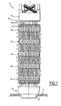
Figure 1 is a schematic side elevation view of a fuel assembly having a lower nozzle according to the invention; -
Figure 2 is an enlarged view of the lower nozzle of the fuel assembly ofFigure 1 ; -
Figure 3 is a bottom view of the lower nozzle ofFigure 2 ; -
Figure 4 is a view illustrating positioning of the fuel assembly ofFigure 1 into a reactor core; and -
Figures 5 and6 are views similar to that ofFigures 2 and 3 of a lower nozzle according to another embodiment. - The
fuel assembly 2 ofFigure 1 is elongated and extends along a longitudinal direction L. - In use, the
fuel assembly 2 is intended to be inserted inside a reactor core and to rest on alower core plate 4 with the longitudinal direction L oriented vertically. In the following, the terms relating to orientation, such as downward, upward..., refer to the longitudinal direction L extending vertically. - The
fuel assembly 2 comprises a bundle offuel rods 6 elongated along the longitudinal direction L and astructure 8 for supporting thefuel rods 6. - The
structure 8 comprises alower nozzle 10 and anupper nozzle 12 spaced longitudinally,guide tubes 14 extending longitudinally between thelower nozzle 10 and theupper nozzle 12 andspacer grids 16 distributed along theguide tubes 14 between thelower nozzle 10 and theupper nozzle 12. - The
upper nozzle 12 is adapted for lifting up thefuel assembly 2 using a clamp. - The
guide tubes 14 connect thelower nozzle 10 to theupper nozzle 12 and maintain the longitudinal spacing between them. Thelower nozzle 10 and theupper nozzle 12 are connected only by theguide tubes 14. - The
guide tubes 14 are tubular for allowing insertion of cluster rods which do not contain fissile material (not shown) inside theguide tubes 14 through theupper nozzle 12. - Each
spacer grid 16 extends transversally and defines a lattice of cells for receiving theguide tubes 14 and thefuel rods 6. Thefuel rods 6 extend through the cells and are supported by thespacer grids 16. - In use, the
fuel assembly 2 rests via thelower nozzle 10 on thelower core plate 4 above a coolant fluid inlet opening 18 of thelower core plate 4. Thelower nozzle 10 supports thefuel assembly 2 and allows coolant fluid to flow vertically upwardly through thelower nozzle 10. - As illustrated in
Figures 2 and 3 , thelower nozzle 10 comprises anupper plate 20, atubular base 22 extending downwardly along a longitudinal axis A from the periphery of theupper plate 20 and atubular inlet 24 extending thebase 22. - The
base 22 extends longitudinally between anupper end 26 and alower end 28. Theupper end 26 and thelower end 28 have square outlines centred on the longitudinal axis A and the length of the outer edges of thelower end 28 is inferior to that of theupper end 26. - The
upper plate 20 extends transversely at theupper end 26 of thebase 22 and is adapted for connecting the guide tubes 14 (represented in dotted line onFigure 2 ) and has openings for allowing coolant fluid flow through theupper plate 20. - The
lower end 28 is intended to rest against thelower core plate 4 at the periphery of an opening 18. Thebase 22 is provided at thelower end 28 with abearing surface 29 extending transversely to the longitudinal axis A. Thebearing surface 29 is symmetric around the longitudinal axis A. - The
lower nozzle 10 has alateral surface 30 extending between the outer periphery of thelower end 28 and the outer periphery of theupper end 26. Thelateral surface 30 is axisymmetric around the longitudinal axis A. - The
lateral surface 30 comprises a longitudinallower segment 32 immediately adjacent thelower end 28, and one longitudinalupper segment 34 extending upwardly from the upper extremity of thelower segment 32, up to theupper end 26. - The
lower segment 32 is of reversed pyramidal shape and comprises fourinclined faces 36 converging downwardly along the longitudinal axis A. Eachinclined face 36 is inclined relative to the longitudinal axis A at an angle θ comprised between 0.5° and 15°. - The pyramid shaped
lower segment 32 is conical and the inclination of eachinclined face 36 relative to the longitudinal axis A equals the half-cone angle of thelower segment 32. - The
lower segment 32 has transverse dimensions decreasing progressively and continuously downwardly along the longitudinal axis A. - The
lower segment 32 tapers downwardly progressively and continuously in side view in any direction perpendicular to the longitudinal axis A, symmetrically relative to the longitudinal axis A. - The
lower segment 32 extends on at least 50% the height H of thelateral surface 30 taken along the longitudinal axis A between thelower end 28 and theupper end 26, preferably at least 70%. - The
upper segment 34 is cylindrical around the longitudinal axis A. It has a constant square transverse cross-section corresponding to the outline of theupper end 26. Theupper segment 34 comprises four flatlongitudinal faces 38 parallel to the longitudinal axis A. - The
inlet 24 extends downwardly along the longitudinal axis A from thelower end 28 of thebase 22. Theinlet 24 is conical of circular transverse cross-section and downwardly converging. - The
fuel assembly 2 might bend along the longitudinal direction L due to severe operating conditions and itsstructure 8 in which thelower nozzle 10 and theupper nozzle 12 are connected by theguide tubes 14 only. - During insertion of the
fuel assembly 2 beside anadjacent fuel assembly 40, thefuel assembly 2 is lifted down with controlling the position of theupper nozzle 12. However, as illustrated onFigure 4 , thelower nozzle 10 may offset laterally and/or be inclined relative to the vertical direction due to the bending and might abut by itslower end 28 or grate by itslateral surface 30 against the lower nozzle of theadjacent fuel assembly 40. - The
lower end 28 having an outline of smaller transverse dimensions than that of theupper end 26 limits the risk that thelower end 28 will abut the lower nozzle of theadjacent fuel assembly 40. - The tapered
lower segment 32 limits the risk of grating with the lower nozzle of theadjacent fuel assembly 40. Any contact will be delayed in the stroke of the downward movement of thefuel assembly 2 and progressive thus limiting the risk of damages. Any gratings will occur on a reduced longitudinal stroke. - The continuous and progressive tapering of the
lower segment 32 ensures that thelower segment 32 is smooth and has no protruding abutment portion. - The extension of the tapered
lower segment 32 on a significant portion of the height H of thelower nozzle 10 allows maintaining sufficient transverse dimensions for the bearingsurface 29 of thelower end 28 which has to support the weight of thefuel assembly 2 while allowing significant reduction of abutment risks and grating risks. - In an example, the height H of the
lower nozzle 10 taken between thelower end 28 and theupper end 26 is of approximately 105 mm, and the height of the taperedlower segment 32 is of 100 mm. - The
conical inlet 24 provide similar advantages with respect to the edge of theopening 18 of thelower core plate 4 into which theinlet 24 is inserted during positioning of thefuel assembly 2 into the reactor core. - The
upper segment 34 havingfaces 38 parallel to the longitudinal axis A allows creating a narrow passage having an important flow resistance between the adjacent lower nozzles which can limit the flow of coolant fluid flowing between the adjacent lower nozzles and bypassing the fuel assemblies. - The proportion of the lower segment relative to the upper segment is chosen to lower abutment and grating risks or consequences while limiting coolant fluid flows bypassing the fuel assemblies.
- On
Figure 5 , the numeral references ofFigures 1 - 4 are used for the similar elements. - The
lower nozzle 42 ofFigure 5 differs from that ofFigure 1 - 4 by the feature that thebase 22 comprises atubular skirt 44 extending downwardly from the periphery of theupper plate 20 and fourcorner feet 46 each extending downwardly from a respective corner of the skirt 44 (only twofeet 46 are visible onFigure 5 ). - Each pair of
feet 46 defines with thelower edge 47 of the skirt 44 a lateral opening. Eachfoot 46 is provided at itslower end 48 with a lower bearing face for resting onto alower core plate 4. The lower ends 48 of thefeet 46 define thelower end 28 of thebase 22. Thelower end 28 has a square outline 50 (represented in dash-doted lines onFigure 6 ). - The
lateral surface 30 of thelower nozzle 42 extends on thefeet 46 and on theskirt 44. Thelateral surface 30 exhibits an overall reverse pyramidal shape and comprises a downwardly taperinglower segment 32 of downwardly decreasing square cross-section having fourfaces 36 and a cylindricalupper segment 34 of constant square cross-section. - The
lower segment 32 extends longitudinally from thelower end 28 up to a level above thelower edge 47 of theskirt 44 and theupper segment 34 extends in the remaining portion of theskirt 44. In an alternative, thelower segment 32 extends to a level below theskirt 44. - The upper face and the lower face of the lower nozzle are not limited to square outlines as illustrated in the embodiments of
Figures 1 - 4 and5 . - In an variant for fuel assemblies of hexagonal transverse cross-section, the lower nozzle has an upper face and an lower face of hexagonal outlines and the tapered segment of the lateral surface has a reversed pyramidal shape of hexagonal base with faces inclined relative to the longitudinal axis A.
- More generally, the lower nozzle has transverse cross-section of polygonal outline and the tapered segment of the lateral face of the lower nozzle is of reversed pyramidal shape with its faces inclined relative to the longitudinal axis A.
- The tapered segment is not limited to conical surfaces such as pyramid shaped surfaces and may be more generally a ruled surface.
- In an variant, the lower nozzle has an upper surface of polygonal outline (e.g. hexagonal outline), a lower surface of circular outline and the tapered segment is a ruled surface defined by rectilinear lines passing by a polygonal outline and a circular outline, the rectilinear lines being inclined inwardly and downwardly relative to the longitudinal axis A.
- The tapered segment is not limited to ruled surface and may exhibit concavity or convexity in the longitudinal direction.
- In a general manner, the tapered segment tapers downwardly continuously and progressively in side view in any transverse direction perpendicular to the longitudinal axis A, preferably symmetrically relative to the longitudinal axis A of the lower nozzle.
Claims (11)
- Lower nozzle (10, 42) for nuclear fuel assembly (2) for use in a pressurized water reactor (PWR), of the type comprising an upper end (26) and a lower end (28) for the lower nozzle (10, 42) to rest on a lower core plate (4) of a reactor core and a lateral surface (30) extending along a longitudinal axis (A) from the lower end (28) to the upper end (26), wherein the lateral surface (30) comprises a longitudinal segment (32) tapering downwardly progressively and continuously along the longitudinal axis (A) and extending on at least 50% of the height (H) of the lateral surface (30).
- Lower nozzle according to claim 1, wherein the tapered longitudinal segment (32) tapers downwardly continuously and progressively in side view in any transverse direction perpendicular to the longitudinal axis (A).
- Lower nozzle according to claim 1 or 2, wherein the tapered longitudinal segment (32) tapers symmetrically relative to the longitudinal axis (A).
- Lower nozzle according to any one of the preceding claims, wherein the tapered longitudinal segment (32) is ruled.
- Lower nozzle according to any one of the preceding claims, wherein the tapered longitudinal segment (32) is conical.
- Lower nozzle according to claim 5, wherein the tapered longitudinal segment (32) is of polygonal transverse cross-section, namely of quadratic or hexagonal transverse cross-section.
- Lower nozzle according to claim 5 or 6, wherein the half cone angle of the tapered longitudinal segment (32) is comprised between 0.5° and 15°.
- Lower nozzle according to any one of the preceding claims, wherein the tapered longitudinal segment (32) extends on at least 70% of the height (H) of the lateral surface (30).
- Lower nozzle according to any one of the preceding claims, wherein the lateral surface (30) comprises a cylindrical segment (34) extending the tapered longitudinal segment (32) upwardly to the upper end (26).
- Lower nozzle according to any one of the preceding claims, comprising a tubular water inlet (24) extending the lower nozzle along the longitudinal axis (A) downwardly from the lower end (28), the water inlet (24) having an outer surface of tapering downwardly progressively and continuously.
- Nuclear fuel assembly (2) for use in a pressurized water reactor (PWR), comprising a bundle of elongated fuel rods (6) and an structure (8) for supporting the fuel rods, the structure comprising a lower nozzle (10, 42) and an upper nozzle (12) spaced longitudinally, guide tubes (14) connecting between the nozzles (10, 12) and spacer grids (16) secured to and distributed along the length of the guide tubes (14), the fuel rods (6) being supported by the spacer grids (16), wherein the lower nozzle (10) is a lower nozzle according to any one of the preceding claims.
Priority Applications (7)
| Application Number | Priority Date | Filing Date | Title |
|---|---|---|---|
| EP08305799A EP2187402B1 (en) | 2008-11-12 | 2008-11-12 | Lower nozzle for nuclear fuel assembly for pressurized water reactor |
| AT08305799T ATE541296T1 (en) | 2008-11-12 | 2008-11-12 | LOWER NOZZLE OF A FUELS ASSEMBLY FOR A PRESSURIZED WATER REACTOR |
| ES08305799T ES2379126T3 (en) | 2008-11-12 | 2008-11-12 | Lower nozzle for nuclear fuel assembly for a pressurized water reactor |
| US13/128,598 US20110280361A1 (en) | 2008-11-12 | 2009-11-09 | Lower nozzle for nuclear fuel assembly for pressurized water reactor |
| JP2011535987A JP2012508389A (en) | 2008-11-12 | 2009-11-09 | Lower nozzle of nuclear fuel assembly for pressurized water reactor |
| PCT/EP2009/064856 WO2010055015A1 (en) | 2008-11-12 | 2009-11-09 | Lower nozzle for nuclear fuel assembly for pressurized water reactor. |
| CN2009801530267A CN102272857A (en) | 2008-11-12 | 2009-11-09 | Lower nozzle for nuclear fuel assembly for pressurized water reactor |
Applications Claiming Priority (1)
| Application Number | Priority Date | Filing Date | Title |
|---|---|---|---|
| EP08305799A EP2187402B1 (en) | 2008-11-12 | 2008-11-12 | Lower nozzle for nuclear fuel assembly for pressurized water reactor |
Publications (2)
| Publication Number | Publication Date |
|---|---|
| EP2187402A1 true EP2187402A1 (en) | 2010-05-19 |
| EP2187402B1 EP2187402B1 (en) | 2012-01-11 |
Family
ID=40428179
Family Applications (1)
| Application Number | Title | Priority Date | Filing Date |
|---|---|---|---|
| EP08305799A Not-in-force EP2187402B1 (en) | 2008-11-12 | 2008-11-12 | Lower nozzle for nuclear fuel assembly for pressurized water reactor |
Country Status (7)
| Country | Link |
|---|---|
| US (1) | US20110280361A1 (en) |
| EP (1) | EP2187402B1 (en) |
| JP (1) | JP2012508389A (en) |
| CN (1) | CN102272857A (en) |
| AT (1) | ATE541296T1 (en) |
| ES (1) | ES2379126T3 (en) |
| WO (1) | WO2010055015A1 (en) |
Families Citing this family (3)
| Publication number | Priority date | Publication date | Assignee | Title |
|---|---|---|---|---|
| EP2839481B1 (en) * | 2012-04-17 | 2017-08-02 | Babcock & Wilcox MPower, Inc. | Lower end fitting locating pins |
| US10665353B2 (en) * | 2013-05-22 | 2020-05-26 | Westinghouse Electric Company Llc | VVER-1000 fuel assembly bottom nozzle |
| JP2015017808A (en) * | 2013-07-08 | 2015-01-29 | 株式会社東芝 | Apparatus and method of gripping upper tie plate of fuel assembly |
Citations (4)
| Publication number | Priority date | Publication date | Assignee | Title |
|---|---|---|---|---|
| JPS5985993A (en) * | 1982-11-08 | 1984-05-18 | 三菱原子力工業株式会社 | Nuclear fuel assembly |
| FR2585499A1 (en) * | 1985-07-29 | 1987-01-30 | Fragema Framatome & Cogema | HYDRAULIC HOLDING DEVICE FOR NUCLEAR FUEL ASSEMBLY AND NUCLEAR REACTOR INCLUDING APPLICATION |
| WO1995014996A1 (en) * | 1993-11-25 | 1995-06-01 | Abb Atom Ab | Fuel assembly with guide thimbles including locking elements for a nuclear reactor |
| FR2848328A1 (en) * | 2002-12-10 | 2004-06-11 | Framatome Anp | METHOD AND DEVICE FOR LOADING A FUEL ASSEMBLY IN THE HEART OF A NUCLEAR REACTOR. |
Family Cites Families (4)
| Publication number | Priority date | Publication date | Assignee | Title |
|---|---|---|---|---|
| GB1190409A (en) * | 1966-09-23 | 1970-05-06 | Gen Electric | Nuclear Reactor Fuel Bundle |
| JPH02167496A (en) * | 1988-12-21 | 1990-06-27 | Nippon Nuclear Fuel Dev Co Ltd | Nuclear fuel assembly |
| JPH06308266A (en) * | 1993-04-22 | 1994-11-04 | Toshiba Corp | Fuel structure for nuclear reactor and fuel replacing method |
| FR2910170B1 (en) * | 2006-12-13 | 2009-04-03 | Areva Np Sas | LOWER CAP WITH AN ANTI-DEBRIS DEVICE FOR CHICAN NUCLEAR FUEL ASSEMBLY AND CORRESPONDING ASSEMBLY |
-
2008
- 2008-11-12 ES ES08305799T patent/ES2379126T3/en active Active
- 2008-11-12 AT AT08305799T patent/ATE541296T1/en active
- 2008-11-12 EP EP08305799A patent/EP2187402B1/en not_active Not-in-force
-
2009
- 2009-11-09 WO PCT/EP2009/064856 patent/WO2010055015A1/en not_active Ceased
- 2009-11-09 CN CN2009801530267A patent/CN102272857A/en active Pending
- 2009-11-09 JP JP2011535987A patent/JP2012508389A/en active Pending
- 2009-11-09 US US13/128,598 patent/US20110280361A1/en not_active Abandoned
Patent Citations (4)
| Publication number | Priority date | Publication date | Assignee | Title |
|---|---|---|---|---|
| JPS5985993A (en) * | 1982-11-08 | 1984-05-18 | 三菱原子力工業株式会社 | Nuclear fuel assembly |
| FR2585499A1 (en) * | 1985-07-29 | 1987-01-30 | Fragema Framatome & Cogema | HYDRAULIC HOLDING DEVICE FOR NUCLEAR FUEL ASSEMBLY AND NUCLEAR REACTOR INCLUDING APPLICATION |
| WO1995014996A1 (en) * | 1993-11-25 | 1995-06-01 | Abb Atom Ab | Fuel assembly with guide thimbles including locking elements for a nuclear reactor |
| FR2848328A1 (en) * | 2002-12-10 | 2004-06-11 | Framatome Anp | METHOD AND DEVICE FOR LOADING A FUEL ASSEMBLY IN THE HEART OF A NUCLEAR REACTOR. |
Also Published As
| Publication number | Publication date |
|---|---|
| WO2010055015A1 (en) | 2010-05-20 |
| CN102272857A (en) | 2011-12-07 |
| EP2187402B1 (en) | 2012-01-11 |
| JP2012508389A (en) | 2012-04-05 |
| ES2379126T3 (en) | 2012-04-23 |
| ATE541296T1 (en) | 2012-01-15 |
| US20110280361A1 (en) | 2011-11-17 |
Similar Documents
| Publication | Publication Date | Title |
|---|---|---|
| US4795608A (en) | Nuclear fuel assembly | |
| EP2187402B1 (en) | Lower nozzle for nuclear fuel assembly for pressurized water reactor | |
| EP1548749A3 (en) | Nuclear reactor fuel assemblies | |
| US6310931B1 (en) | Device and method for locking rods in a bottom tie plate of a fuel assembly | |
| KR20130102036A (en) | Optimized flower tubes and optimized advanced grid configurations | |
| CN101589438B (en) | Grid with saddle support and corresponding nuclear fuel assembly | |
| SE503626C2 (en) | Heat fuel elements and method for locking spacers in one | |
| RU2473989C1 (en) | Nuclear reactor fuel assembly | |
| US20070076840A1 (en) | Nuclear fuel assembly comprising a reinforcing mesh device and the use of one such device in a nuclear fuel assembly | |
| WO2013172889A1 (en) | Lower end fitting for nuclear fuel assembly made from intersecting metal strips | |
| EP2592199B1 (en) | Tower for a wind energy device | |
| US20140064435A1 (en) | Nuclear fuel assembly for boiling water reactor comprising a fuel channel spacer | |
| US20140037041A1 (en) | Spacer grid for nuclear fuel assembly for reducing high frequency vibration | |
| EP0289732A2 (en) | Reconstitutable nuclear fuel assembly | |
| KR101474548B1 (en) | Nuclear fuel assembly having a protective grid to prevent flow-induced vibration | |
| US20150332793A1 (en) | Natural-Circulation Boiling Water Reactor and Chimney Therefor | |
| CA2857076C (en) | Decanter | |
| JP6560861B2 (en) | Fuel assembly | |
| CN106809505B (en) | Fixing support for neutron temperature measurement channel | |
| EP3198610A1 (en) | Fuel assembly for boiling water reactor | |
| CN204407015U (en) | A kind of fuel assembly bottom nozzle of dual anti-foreign matter | |
| US8548113B2 (en) | Debris mitigation upper tie plates and fuel bundles using the same | |
| CN219658395U (en) | Control rod assembly storage device | |
| CN116635952B (en) | Spare grid elements, spacer grid, and nuclear fuel assembly in nuclear fuel assembly spacer grid | |
| US8675804B2 (en) | Boiling water reactor fuel support casting flow limiter |
Legal Events
| Date | Code | Title | Description |
|---|---|---|---|
| PUAI | Public reference made under article 153(3) epc to a published international application that has entered the european phase |
Free format text: ORIGINAL CODE: 0009012 |
|
| AK | Designated contracting states |
Kind code of ref document: A1 Designated state(s): AT BE BG CH CY CZ DE DK EE ES FI FR GB GR HR HU IE IS IT LI LT LU LV MC MT NL NO PL PT RO SE SI SK TR |
|
| AX | Request for extension of the european patent |
Extension state: AL BA MK RS |
|
| 17P | Request for examination filed |
Effective date: 20100701 |
|
| 17Q | First examination report despatched |
Effective date: 20100820 |
|
| AKX | Designation fees paid |
Designated state(s): AT BE BG CH CY CZ DE DK EE ES FI FR GB GR HR HU IE IS IT LI LT LU LV MC MT NL NO PL PT RO SE SI SK TR |
|
| GRAP | Despatch of communication of intention to grant a patent |
Free format text: ORIGINAL CODE: EPIDOSNIGR1 |
|
| GRAS | Grant fee paid |
Free format text: ORIGINAL CODE: EPIDOSNIGR3 |
|
| GRAA | (expected) grant |
Free format text: ORIGINAL CODE: 0009210 |
|
| AK | Designated contracting states |
Kind code of ref document: B1 Designated state(s): AT BE BG CH CY CZ DE DK EE ES FI FR GB GR HR HU IE IS IT LI LT LU LV MC MT NL NO PL PT RO SE SI SK TR |
|
| REG | Reference to a national code |
Ref country code: GB Ref legal event code: FG4D |
|
| REG | Reference to a national code |
Ref country code: CH Ref legal event code: EP |
|
| REG | Reference to a national code |
Ref country code: AT Ref legal event code: REF Ref document number: 541296 Country of ref document: AT Kind code of ref document: T Effective date: 20120115 |
|
| REG | Reference to a national code |
Ref country code: IE Ref legal event code: FG4D |
|
| REG | Reference to a national code |
Ref country code: DE Ref legal event code: R096 Ref document number: 602008012637 Country of ref document: DE Effective date: 20120315 |
|
| REG | Reference to a national code |
Ref country code: ES Ref legal event code: FG2A Ref document number: 2379126 Country of ref document: ES Kind code of ref document: T3 Effective date: 20120423 |
|
| REG | Reference to a national code |
Ref country code: NL Ref legal event code: VDEP Effective date: 20120111 |
|
| PG25 | Lapsed in a contracting state [announced via postgrant information from national office to epo] |
Ref country code: SI Free format text: LAPSE BECAUSE OF FAILURE TO SUBMIT A TRANSLATION OF THE DESCRIPTION OR TO PAY THE FEE WITHIN THE PRESCRIBED TIME-LIMIT Effective date: 20120111 |
|
| LTIE | Lt: invalidation of european patent or patent extension |
Effective date: 20120111 |
|
| PG25 | Lapsed in a contracting state [announced via postgrant information from national office to epo] |
Ref country code: BE Free format text: LAPSE BECAUSE OF FAILURE TO SUBMIT A TRANSLATION OF THE DESCRIPTION OR TO PAY THE FEE WITHIN THE PRESCRIBED TIME-LIMIT Effective date: 20120111 Ref country code: HR Free format text: LAPSE BECAUSE OF FAILURE TO SUBMIT A TRANSLATION OF THE DESCRIPTION OR TO PAY THE FEE WITHIN THE PRESCRIBED TIME-LIMIT Effective date: 20120111 Ref country code: IS Free format text: LAPSE BECAUSE OF FAILURE TO SUBMIT A TRANSLATION OF THE DESCRIPTION OR TO PAY THE FEE WITHIN THE PRESCRIBED TIME-LIMIT Effective date: 20120511 Ref country code: LT Free format text: LAPSE BECAUSE OF FAILURE TO SUBMIT A TRANSLATION OF THE DESCRIPTION OR TO PAY THE FEE WITHIN THE PRESCRIBED TIME-LIMIT Effective date: 20120111 Ref country code: NO Free format text: LAPSE BECAUSE OF FAILURE TO SUBMIT A TRANSLATION OF THE DESCRIPTION OR TO PAY THE FEE WITHIN THE PRESCRIBED TIME-LIMIT Effective date: 20120411 Ref country code: BG Free format text: LAPSE BECAUSE OF FAILURE TO SUBMIT A TRANSLATION OF THE DESCRIPTION OR TO PAY THE FEE WITHIN THE PRESCRIBED TIME-LIMIT Effective date: 20120411 Ref country code: NL Free format text: LAPSE BECAUSE OF FAILURE TO SUBMIT A TRANSLATION OF THE DESCRIPTION OR TO PAY THE FEE WITHIN THE PRESCRIBED TIME-LIMIT Effective date: 20120111 |
|
| PG25 | Lapsed in a contracting state [announced via postgrant information from national office to epo] |
Ref country code: GR Free format text: LAPSE BECAUSE OF FAILURE TO SUBMIT A TRANSLATION OF THE DESCRIPTION OR TO PAY THE FEE WITHIN THE PRESCRIBED TIME-LIMIT Effective date: 20120412 Ref country code: LV Free format text: LAPSE BECAUSE OF FAILURE TO SUBMIT A TRANSLATION OF THE DESCRIPTION OR TO PAY THE FEE WITHIN THE PRESCRIBED TIME-LIMIT Effective date: 20120111 Ref country code: PL Free format text: LAPSE BECAUSE OF FAILURE TO SUBMIT A TRANSLATION OF THE DESCRIPTION OR TO PAY THE FEE WITHIN THE PRESCRIBED TIME-LIMIT Effective date: 20120111 Ref country code: FI Free format text: LAPSE BECAUSE OF FAILURE TO SUBMIT A TRANSLATION OF THE DESCRIPTION OR TO PAY THE FEE WITHIN THE PRESCRIBED TIME-LIMIT Effective date: 20120111 Ref country code: PT Free format text: LAPSE BECAUSE OF FAILURE TO SUBMIT A TRANSLATION OF THE DESCRIPTION OR TO PAY THE FEE WITHIN THE PRESCRIBED TIME-LIMIT Effective date: 20120511 |
|
| REG | Reference to a national code |
Ref country code: AT Ref legal event code: MK05 Ref document number: 541296 Country of ref document: AT Kind code of ref document: T Effective date: 20120111 |
|
| PG25 | Lapsed in a contracting state [announced via postgrant information from national office to epo] |
Ref country code: CY Free format text: LAPSE BECAUSE OF FAILURE TO SUBMIT A TRANSLATION OF THE DESCRIPTION OR TO PAY THE FEE WITHIN THE PRESCRIBED TIME-LIMIT Effective date: 20120111 |
|
| PG25 | Lapsed in a contracting state [announced via postgrant information from national office to epo] |
Ref country code: DK Free format text: LAPSE BECAUSE OF FAILURE TO SUBMIT A TRANSLATION OF THE DESCRIPTION OR TO PAY THE FEE WITHIN THE PRESCRIBED TIME-LIMIT Effective date: 20120111 Ref country code: RO Free format text: LAPSE BECAUSE OF FAILURE TO SUBMIT A TRANSLATION OF THE DESCRIPTION OR TO PAY THE FEE WITHIN THE PRESCRIBED TIME-LIMIT Effective date: 20120111 Ref country code: SE Free format text: LAPSE BECAUSE OF FAILURE TO SUBMIT A TRANSLATION OF THE DESCRIPTION OR TO PAY THE FEE WITHIN THE PRESCRIBED TIME-LIMIT Effective date: 20120111 Ref country code: CZ Free format text: LAPSE BECAUSE OF FAILURE TO SUBMIT A TRANSLATION OF THE DESCRIPTION OR TO PAY THE FEE WITHIN THE PRESCRIBED TIME-LIMIT Effective date: 20120111 Ref country code: EE Free format text: LAPSE BECAUSE OF FAILURE TO SUBMIT A TRANSLATION OF THE DESCRIPTION OR TO PAY THE FEE WITHIN THE PRESCRIBED TIME-LIMIT Effective date: 20120111 |
|
| PLBE | No opposition filed within time limit |
Free format text: ORIGINAL CODE: 0009261 |
|
| STAA | Information on the status of an ep patent application or granted ep patent |
Free format text: STATUS: NO OPPOSITION FILED WITHIN TIME LIMIT |
|
| PG25 | Lapsed in a contracting state [announced via postgrant information from national office to epo] |
Ref country code: IT Free format text: LAPSE BECAUSE OF FAILURE TO SUBMIT A TRANSLATION OF THE DESCRIPTION OR TO PAY THE FEE WITHIN THE PRESCRIBED TIME-LIMIT Effective date: 20120111 Ref country code: SK Free format text: LAPSE BECAUSE OF FAILURE TO SUBMIT A TRANSLATION OF THE DESCRIPTION OR TO PAY THE FEE WITHIN THE PRESCRIBED TIME-LIMIT Effective date: 20120111 |
|
| 26N | No opposition filed |
Effective date: 20121012 |
|
| PG25 | Lapsed in a contracting state [announced via postgrant information from national office to epo] |
Ref country code: AT Free format text: LAPSE BECAUSE OF FAILURE TO SUBMIT A TRANSLATION OF THE DESCRIPTION OR TO PAY THE FEE WITHIN THE PRESCRIBED TIME-LIMIT Effective date: 20120111 |
|
| REG | Reference to a national code |
Ref country code: DE Ref legal event code: R097 Ref document number: 602008012637 Country of ref document: DE Effective date: 20121012 |
|
| REG | Reference to a national code |
Ref country code: CH Ref legal event code: PL |
|
| GBPC | Gb: european patent ceased through non-payment of renewal fee |
Effective date: 20121112 |
|
| PG25 | Lapsed in a contracting state [announced via postgrant information from national office to epo] |
Ref country code: CH Free format text: LAPSE BECAUSE OF NON-PAYMENT OF DUE FEES Effective date: 20121130 Ref country code: LI Free format text: LAPSE BECAUSE OF NON-PAYMENT OF DUE FEES Effective date: 20121130 |
|
| REG | Reference to a national code |
Ref country code: IE Ref legal event code: MM4A |
|
| REG | Reference to a national code |
Ref country code: FR Ref legal event code: ST Effective date: 20130731 |
|
| PG25 | Lapsed in a contracting state [announced via postgrant information from national office to epo] |
Ref country code: IE Free format text: LAPSE BECAUSE OF NON-PAYMENT OF DUE FEES Effective date: 20121112 |
|
| PG25 | Lapsed in a contracting state [announced via postgrant information from national office to epo] |
Ref country code: MT Free format text: LAPSE BECAUSE OF FAILURE TO SUBMIT A TRANSLATION OF THE DESCRIPTION OR TO PAY THE FEE WITHIN THE PRESCRIBED TIME-LIMIT Effective date: 20120111 Ref country code: FR Free format text: LAPSE BECAUSE OF NON-PAYMENT OF DUE FEES Effective date: 20121130 Ref country code: GB Free format text: LAPSE BECAUSE OF NON-PAYMENT OF DUE FEES Effective date: 20121112 |
|
| PG25 | Lapsed in a contracting state [announced via postgrant information from national office to epo] |
Ref country code: TR Free format text: LAPSE BECAUSE OF FAILURE TO SUBMIT A TRANSLATION OF THE DESCRIPTION OR TO PAY THE FEE WITHIN THE PRESCRIBED TIME-LIMIT Effective date: 20120111 Ref country code: MC Free format text: LAPSE BECAUSE OF NON-PAYMENT OF DUE FEES Effective date: 20121130 |
|
| PG25 | Lapsed in a contracting state [announced via postgrant information from national office to epo] |
Ref country code: LU Free format text: LAPSE BECAUSE OF NON-PAYMENT OF DUE FEES Effective date: 20121112 |
|
| PG25 | Lapsed in a contracting state [announced via postgrant information from national office to epo] |
Ref country code: HU Free format text: LAPSE BECAUSE OF FAILURE TO SUBMIT A TRANSLATION OF THE DESCRIPTION OR TO PAY THE FEE WITHIN THE PRESCRIBED TIME-LIMIT Effective date: 20081112 |
|
| REG | Reference to a national code |
Ref country code: DE Ref legal event code: R082 Ref document number: 602008012637 Country of ref document: DE Representative=s name: LAVOIX MUNICH, DE |
|
| PGFP | Annual fee paid to national office [announced via postgrant information from national office to epo] |
Ref country code: DE Payment date: 20191115 Year of fee payment: 12 |
|
| REG | Reference to a national code |
Ref country code: DE Ref legal event code: R119 Ref document number: 602008012637 Country of ref document: DE |
|
| PG25 | Lapsed in a contracting state [announced via postgrant information from national office to epo] |
Ref country code: DE Free format text: LAPSE BECAUSE OF NON-PAYMENT OF DUE FEES Effective date: 20210601 |
|
| PGFP | Annual fee paid to national office [announced via postgrant information from national office to epo] |
Ref country code: ES Payment date: 20231218 Year of fee payment: 16 |
|
| REG | Reference to a national code |
Ref country code: ES Ref legal event code: FD2A Effective date: 20251230 |
|
| PG25 | Lapsed in a contracting state [announced via postgrant information from national office to epo] |
Ref country code: ES Free format text: LAPSE BECAUSE OF NON-PAYMENT OF DUE FEES Effective date: 20241113 |