EP2187160A1 - Radiator - Google Patents
Radiator Download PDFInfo
- Publication number
- EP2187160A1 EP2187160A1 EP08830843A EP08830843A EP2187160A1 EP 2187160 A1 EP2187160 A1 EP 2187160A1 EP 08830843 A EP08830843 A EP 08830843A EP 08830843 A EP08830843 A EP 08830843A EP 2187160 A1 EP2187160 A1 EP 2187160A1
- Authority
- EP
- European Patent Office
- Prior art keywords
- main tank
- radiator
- tank
- coolant water
- upper main
- Prior art date
- Legal status (The legal status is an assumption and is not a legal conclusion. Google has not performed a legal analysis and makes no representation as to the accuracy of the status listed.)
- Withdrawn
Links
Images




Classifications
-
- F—MECHANICAL ENGINEERING; LIGHTING; HEATING; WEAPONS; BLASTING
- F28—HEAT EXCHANGE IN GENERAL
- F28F—DETAILS OF HEAT-EXCHANGE AND HEAT-TRANSFER APPARATUS, OF GENERAL APPLICATION
- F28F9/00—Casings; Header boxes; Auxiliary supports for elements; Auxiliary members within casings
- F28F9/26—Arrangements for connecting different sections of heat-exchange elements, e.g. of radiators
- F28F9/262—Arrangements for connecting different sections of heat-exchange elements, e.g. of radiators for radiators
-
- F—MECHANICAL ENGINEERING; LIGHTING; HEATING; WEAPONS; BLASTING
- F01—MACHINES OR ENGINES IN GENERAL; ENGINE PLANTS IN GENERAL; STEAM ENGINES
- F01P—COOLING OF MACHINES OR ENGINES IN GENERAL; COOLING OF INTERNAL-COMBUSTION ENGINES
- F01P3/00—Liquid cooling
- F01P3/18—Arrangements or mounting of liquid-to-air heat-exchangers
-
- F—MECHANICAL ENGINEERING; LIGHTING; HEATING; WEAPONS; BLASTING
- F28—HEAT EXCHANGE IN GENERAL
- F28D—HEAT-EXCHANGE APPARATUS, NOT PROVIDED FOR IN ANOTHER SUBCLASS, IN WHICH THE HEAT-EXCHANGE MEDIA DO NOT COME INTO DIRECT CONTACT
- F28D1/00—Heat-exchange apparatus having stationary conduit assemblies for one heat-exchange medium only, the media being in contact with different sides of the conduit wall, in which the other heat-exchange medium is a large body of fluid, e.g. domestic or motor car radiators
- F28D1/02—Heat-exchange apparatus having stationary conduit assemblies for one heat-exchange medium only, the media being in contact with different sides of the conduit wall, in which the other heat-exchange medium is a large body of fluid, e.g. domestic or motor car radiators with heat-exchange conduits immersed in the body of fluid
- F28D1/04—Heat-exchange apparatus having stationary conduit assemblies for one heat-exchange medium only, the media being in contact with different sides of the conduit wall, in which the other heat-exchange medium is a large body of fluid, e.g. domestic or motor car radiators with heat-exchange conduits immersed in the body of fluid with tubular conduits
- F28D1/053—Heat-exchange apparatus having stationary conduit assemblies for one heat-exchange medium only, the media being in contact with different sides of the conduit wall, in which the other heat-exchange medium is a large body of fluid, e.g. domestic or motor car radiators with heat-exchange conduits immersed in the body of fluid with tubular conduits the conduits being straight
- F28D1/0535—Heat-exchange apparatus having stationary conduit assemblies for one heat-exchange medium only, the media being in contact with different sides of the conduit wall, in which the other heat-exchange medium is a large body of fluid, e.g. domestic or motor car radiators with heat-exchange conduits immersed in the body of fluid with tubular conduits the conduits being straight the conduits having a non-circular cross-section
- F28D1/05366—Assemblies of conduits connected to common headers, e.g. core type radiators
-
- F—MECHANICAL ENGINEERING; LIGHTING; HEATING; WEAPONS; BLASTING
- F28—HEAT EXCHANGE IN GENERAL
- F28F—DETAILS OF HEAT-EXCHANGE AND HEAT-TRANSFER APPARATUS, OF GENERAL APPLICATION
- F28F9/00—Casings; Header boxes; Auxiliary supports for elements; Auxiliary members within casings
- F28F9/001—Casings in the form of plate-like arrangements; Frames enclosing a heat exchange core
- F28F9/002—Casings in the form of plate-like arrangements; Frames enclosing a heat exchange core with fastening means for other structures
-
- F—MECHANICAL ENGINEERING; LIGHTING; HEATING; WEAPONS; BLASTING
- F28—HEAT EXCHANGE IN GENERAL
- F28F—DETAILS OF HEAT-EXCHANGE AND HEAT-TRANSFER APPARATUS, OF GENERAL APPLICATION
- F28F9/00—Casings; Header boxes; Auxiliary supports for elements; Auxiliary members within casings
- F28F9/02—Header boxes; End plates
-
- F—MECHANICAL ENGINEERING; LIGHTING; HEATING; WEAPONS; BLASTING
- F28—HEAT EXCHANGE IN GENERAL
- F28F—DETAILS OF HEAT-EXCHANGE AND HEAT-TRANSFER APPARATUS, OF GENERAL APPLICATION
- F28F9/00—Casings; Header boxes; Auxiliary supports for elements; Auxiliary members within casings
- F28F9/02—Header boxes; End plates
- F28F9/0231—Header boxes having an expansion chamber
-
- F—MECHANICAL ENGINEERING; LIGHTING; HEATING; WEAPONS; BLASTING
- F01—MACHINES OR ENGINES IN GENERAL; ENGINE PLANTS IN GENERAL; STEAM ENGINES
- F01P—COOLING OF MACHINES OR ENGINES IN GENERAL; COOLING OF INTERNAL-COMBUSTION ENGINES
- F01P3/00—Liquid cooling
- F01P3/18—Arrangements or mounting of liquid-to-air heat-exchangers
- F01P2003/185—Arrangements or mounting of liquid-to-air heat-exchangers arranged in parallel
-
- F—MECHANICAL ENGINEERING; LIGHTING; HEATING; WEAPONS; BLASTING
- F28—HEAT EXCHANGE IN GENERAL
- F28F—DETAILS OF HEAT-EXCHANGE AND HEAT-TRANSFER APPARATUS, OF GENERAL APPLICATION
- F28F2265/00—Safety or protection arrangements; Arrangements for preventing malfunction
- F28F2265/18—Safety or protection arrangements; Arrangements for preventing malfunction for removing contaminants, e.g. for degassing
Definitions
- the present invention relates to a radiator including a radiator core.
- a conventional work vehicle such as bulldozer is equipped with a module type radiator that is divided into a plurality of core units so that if the radiator core is partially damaged by vibration, shock and the like the damaged part can be simply replaced.
- Patent Document 1 discloses a radiator that facilitates reduction of space for replacing its core unit, simplification of replacing its core unit, and the like.
- Patent Document 1 discloses module type radiators 100 and 100A shown in Figs. 8(a) and 8(b) .
- the module type radiators 100 and 100A shown in Figs. 8(a) and 8(b) , respectively, have the same basic configuration. Therefore, each of elements having a same function is respectively attached with the same reference numerals in these Figures.
- Each of the radiators 100 and 100A shown in Figs. 8(a) and 8(b) respectively, includes upper and lower main tanks 101 and 102 that are arranged on the upper and lower sides, and a plurality of core units 106, each of which includes upper and lower auxiliary tanks 103 and 104 that are arranged on the upper and lower sides to interpose a heat exchanging portion 105 between the upper and lower auxiliary tanks 103 and 104.
- the plurality of core units 106 are arranged in parallel to each other on the lower main tank 102.
- the upper main tank 101 is arranged in a position that is offset toward the vehicle front side relative to the lower main tank 102 in the plan view.
- the core units 106 can be removed/inserted from directly above. For this reason, it is possible to facilitate reduction of space for replacing the core unit, simplification of the replacement, and the like.
- the upper auxiliary tank 103 in the core unit 106 is arranged at a position lower than the upper main tank 101.
- the upper surface of the upper auxiliary tank 103 and the side surface of the upper main tank 101 are connected to each other by a coolant water conduit pipe 107.
- the side surface of the upper auxiliary tank 103 and the lower surface of the upper main tank 101 are connected by a coolant water conduit pipe 107A.
- radiators 100 and 100A shown in Figs. 8(a) and 8(b) respectively, arrangement space for the upper main tank 101 is required above the core unit 106. For this reason, only increasing the entire height of the radiator 100 can increase the height of the core unit 106. Accordingly, from the viewpoint of the aforementioned frontward visibility issue, there is a problem in that the height of the core unit 106 cannot be increased.
- radiators include a core unit having the same size
- cooling efficiency of the radiator may be reduced by circulation of air bubbles.
- the height of core units in a radiator could be increased as high as possible, it is very important to prevent circulation of air bubbles contained in coolant water in terms of ensuring the cooling performance of the radiator.
- a radiator according to a first aspect of the present invention includes a heat exchanger, an upper auxiliary tank, a lower auxiliary tank, an upper main tank, and a lower main tank.
- the upper auxiliary tank is mounted on the upper surface of the heat exchanger.
- the lower auxiliary tank is mounted on the lower surface of the heat exchanger so that the heat exchanger is interposed between the lower auxiliary tank and the upper auxiliary tank.
- the upper main tank is arranged at the substantially same height as the upper auxiliary tank, and is connected to the upper auxiliary tank via a coolant water conduit pipe.
- the upper main tank has a coolant water inlet on the lower surface the upper main tank.
- the lower main tank is arranged under the upper main tank at an offset position relative to the upper main tank in the plan view.
- the lower main tank is connected to the lower auxiliary tank.
- the coolant water inlet for feeding coolant water into the upper main tank is thus arranged in the lower part of the upper main tank so that the coolant water is fed from the bottom of the upper main tank. Therefore, it is possible to effectively prevent that air enters the coolant water, and to effectively prevent reduction of the cooling performance of the radiator.
- the upper main tank is arranged at the substantially same height as the upper auxiliary tank, and the upper main tank and the upper auxiliary tank are connected to each other via the coolant water conduit pipe, piping space is not required that has been required above each upper auxiliary tank in the past. For this reason, even in the case where the radiator according to the present invention has the same entire height as the known module type radiator, the height of its core unit can be greater. Therefore, it is possible to improve the cooling performance.
- the lower surface of the upper main tank is arranged at the substantially same height as the lower surface of the upper auxiliary tank.
- the upper surface of the upper main tank is arranged at a higher position than the upper surface of the upper auxiliary tank.
- the upper main tank has a coolant water outlet that discharges coolant water in the upper auxiliary tank via the coolant water conduit pipe.
- the upper main tank further includes a baffle that is arranged in proximity to the coolant water outlet to suppress passage of air bubbles through the coolant water outlet.
- the upper main tank is arranged at an offset position toward an engine side relative to the lower main tank. Accordingly, coolant water that is warmed in an engine can flow into the upper main tank, which is arranged in proximity to the engine. For this reason, the length of the coolant water conduit pipe can be minimized, and the height of the heat exchanger can be greater. Therefore, it is possible to improve the cooling efficiency and to provide efficient arrangement of components in the engine compartment.
- the radiator in the radiator according to the first or second aspect of the present invention, includes a plurality of core units, each of which includes the heat exchanger, the upper auxiliary tank and the lower auxiliary tank so that the radiator is configured in a module. Accordingly, even when one core unit of the plurality of modularized core units is replaced due to malfunction, since the upper main tank is arranged at the offset position in the plan view relative to the lower main tank, the core unit can be removed/inserted from directly above. Therefore, it is possible to facilitate reduction of space for replacing the core unit, simplification of the replacement, and the like.
- a radiator according to a sixth aspect of the present invention includes a heat exchanger, an upper auxiliary tank, a lower auxiliary tank, an upper main tank, and a lower main tank.
- the upper auxiliary tank is mounted on the upper surface of the heat exchanger.
- the lower auxiliary tank is mounted on the lower surface of the heat exchanger so that the heat exchanger is interposed between the lower auxiliary tank and the upper auxiliary tank.
- the upper main tank is arranged at the substantially same height as said upper auxiliary tank.
- the side surface of the upper main tank is connected to the side surface of the upper auxiliary tank via a coolant water conduit pipe.
- the lower main tank is arranged under the upper main tank at an offset position relative to the upper main tank in the plan view.
- the lower main tank is connected to the lower auxiliary tank.
- the radiator according to the present invention has the same entire height as the known radiator, the height of its core unit can be greater. As a result, it is possible to improve the cooling performance of the radiator.
- the radiator in the radiator according to a seventh aspect of the present invention, includes a plurality of core units, each of which includes the heat exchanger, the upper auxiliary tank and the lower auxiliary tank so that the radiator is configured in a module. Accordingly, even when one of core unit among the plurality of modularized core units is replaced due to malfunction, since the upper main tank is arranged at the offset position in the plan view relative to the lower main tank, the core unit can be removed/inserted from directly above. Therefore, it is possible to facilitate reduction of space for replacing the core unit, simplification of the replacement, and the like.
- the coolant water conduit pipe is a straight pipe. Since a straight pipe is provided as the coolant water conduit pipe that connects the side surface of the upper auxiliary tank in the core unit and the side surface of the upper main tank to each other, the height of the core unit can be maximized even in the case where the thus-configured radiator has the same height as the known radiator.
- the radiator in the radiator according to the sixth or seventh aspect of the present invention, is installed in a vehicle.
- the upper main tank is mounted to a vehicle body frame that composes the frame of the vehicle.
- this module type radiator since the upper main tank is thus mounted to a vehicle body frame that composes the frame of the vehicle, it is possible to firmly keep the arrangement of the upper main tank.
- the radiator in the radiator according to a tenth aspect of the present invention, is accommodated in an engine compartment of a vehicle.
- the upper main tank is configured integrally with an exterior cover that composes the roof of the engine compartment.
- the radiators are accommodated in an engine compartment of a vehicle, it is generally necessary to arrange a gap between an exterior cover that composes the roof of the engine compartment, and an upper main tank.
- the upper main tank is configured integrally with the exterior cover, it is possible to further increase the height of core unit corresponding to the gap. Therefore, it is possible to further improve the cooling performance of the radiator.
- Fig. 1 is a schematic side view of a bulldozer equipped with a module type radiator according to one embodiment of the present invention.
- Frontward, rearward, rightward and leftward in the following description refer to frontward, rearward, rightward and leftward of the bulldozer.
- an engine compartment 6 is disposed in a front part of a vehicle body unit 3 that includes track-type drive units 2.
- the engine compartment 6 accommodates an engine 4 and a module type radiator 5.
- An operator compartment 7 is disposed in a rear part of the vehicle body unit 3.
- a blade 8 is disposed in front of the vehicle body unit 3. This blade 8 is moved upward and downward by left and right lift cylinders (only left cylinder is shown) 10 mounted on the vehicle body frame 9.
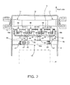
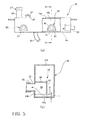
- Figs. 2 , 3 and 4 are plan, front and side views of the radiator according to this embodiment in an installation state, respectively.
- the radiator 5 is arranged between a reinforcement member 12 and the engine 4.
- the reinforcement member 12 connects right and left supporting devices 11 to each other that support the right and left lift cylinders 10 (see Fig. 1 ).
- the radiator 5 includes upper and lower main tanks 15 and 16, a radiator core 17, and a radiator frame 18, as shown in Fig. 3 .
- the upper and lower main tanks 15 and 16 are arranged in parallel to each other on the upper and lower sides of the radiator 5.
- the radiator core 17 is arranged on the lower main tank 16.
- the radiator frame 18 is formed in a frame shape that encloses the radiator core 17.
- the radiator core 17 is supported by the radiator frame 18 and the lower main tank 16.
- the upper main tank 15 has a rectangular parallelepiped shape.
- the upper main tank 15 is spaced at a certain interval rearwards away from the radiator core 17, and is thus arranged at an offset position relative to the lower main tank 16 in the plan view.
- the upper main tank 15 is arranged at an offset position toward an engine 4 side relative to the lower main tank 16.
- a bottom plate 15a composes the lower surface of the upper main tank 15, and has a coolant water inlet 20 that extends downward.
- This coolant water inlet 20 is connected to a water jacket 63 of the engine 4 via a coolant water path (piping means) 61.
- the coolant water from the engine 4 flows into the upper main tank 15 through the coolant water inlet 20. Since the coolant water thus flows into the upper main tank 15 through the coolant water inlet 20 that is arranged on the bottom plate 15a of the upper main tank 15, the coolant water is fed from the bottom of the upper main tank 15. Accordingly, it is possible to prevent that the coolant water contains air.
- a front plate 15b composes the front surface of the upper main tank 15, and has first and second coolant water outlets 21 and 22 that extend straightly frontward.
- a right side plate 15c composes the right side surface of the upper main tank 15, and has a third coolant water outlet 23 that extends straightly rightward.
- a radiator cap attachment port 24 is arranged on an upper plate 15d of the upper main tank 15.
- a pressurizing radiator cap 25 with a ventilation valve is attached to the radiator cap attachment port 24.
- the base part of the radiator cap attachment port 24 is connected to a reservoir tank (not shown). Thus, the pressure in the radiator 5 is kept constant by the radiator cap 25.
- the coolant water flows between the upper main tank 15 and the reservoir tank in the pressurization by radiator cap 25 so that a required amount of coolant water is constantly hold in the radiator 5.
- the collecting gas is discharged to outside air by operation of the ventilation valve of the radiator cap 25.
- Reference numerals 26 and 27 show a coolant water feed port and a feed cap, respectively.
- the coolant water feed port 27 is arranged on the upper surface of the upper main tank 15. Thus, the default water level in the coolant water feed port 27 is located higher than the upper main tank 15.
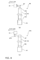
- baffle devices (baffles) 55 are arranged correspondingly to coolant water outlets (outlets) 21 to 23 inside the upper main tank 15.
- the baffle device 55 corresponding to the second coolant water outlet 22 is illustratively described.
- the baffle device 55 is spaced at a small gap t away from the bottom surface of the upper main tank 15, as shown in Fig. 5(b) .
- the upper main tank 15 has partitioned chambers 58. Each of the partitioned chambers 58 is partitioned by front plate 15b, a sectionally arch-shaped upward convex plate 56 and an end wall plate 57, and is opened only downward and toward the second coolant water outlet 22 side.
- the baffle device 55 is configured so that the coolant water in the upper main tank 15 flows from the gap t into the second coolant water outlet 22 through the partitioned chamber 58 as shown by an arrow Q in Fig. 5(b) .
- the thus-configured baffle device 55 is arranged in the upper main tank 15, as for air bubbles that are entrained in the coolant water that flows into the upper main tank 15, it is possible to avoid feeding such air bubbles from the interior of the upper main tank 15 to the downstream side. Therefore, it is possible to more effectively prevent cooling performance degradation of the radiator due to circulation of the air bubbles that are entrained in the coolant water.
- the lower main tank 16 has a rectangular parallelepiped shape.
- the coolant water outlet 28 is arranged on a rear plate 16a. As shown in Fig. 4 , the coolant water outlet 28 is connected to the water jacket 63 of the engine 4 via the coolant water path 61 and the water pump 62 so that the coolant water that has been cooled by the radiator core 17 is fed from the lower main tank 16 into the water jacket 63 of the engine 4, and is then fed into the coolant water inlet 20 through a thermostat 64.
- the upper main tank 15 and the lower main tank 16 are connected to each other by a communicating tube 29 (shown only in Fig. 4 for ease of illustration). Accordingly, even if air collects in the lower main tank 16, the air can be easily moved toward the upper main tank 15. The air that is moved toward the upper main tank 15 can be discharged by operation of the ventilation valve of the radiator cap 25. Thus, air in the radiator 5 can be easily removed. Therefore, it is possible to surely prevent air collection in the radiator 5.
- the communicating tube 29 is piped not to extend over the exposure surface of the radiator core 17 so that cooling air flow for the radiator core 17 is not be interrupted.
- the radiator core 17 is composed of first, second and third core units 31, 32 and 33 that are arranged on the lower main tank 16 in parallel to each other from the left side to the right side as shown in Fig. 3 .
- Each of the core units 31 to 33 includes upper and lower auxiliary tanks 35 and 36, and a heat exchanging portion (heat exchanger) 39.
- the upper and lower auxiliary tanks 35 and 36 has a low-profile rectangular parallelepiped shape, and are arranged on the upper and lower sides.
- the heat exchanging portion 39 includes a plurality of tubes 37 and radiating fins 38.
- the plurality of tubes 37 couple the auxiliary tanks 35 and 36 to each other.
- the radiating fins 38 are arranged around the tubes 37.
- the coolant water in the upper auxiliary tank 35 is cooled by air that passes through the radiating fins 38 when flowing toward the lower auxiliary tank 36 through the tubes 37.
- the upper auxiliary tank 35 in each of the core units 31 to 33 is arranged at the substantially same height as the upper main tank 15.
- the lower surfaces of the upper auxiliary tank 35 and the upper main tank 15 are arranged at the substantially same height as each other, and the upper surface of the upper main tank 15 is arranged higher than the upper surface of the upper auxiliary tank 35.
- Coolant water inlets 40 discussed later
- the coolant water outlets 21, 22 and 23 are arranged at the same height as each other.
- a rear plate 35a composes the rear surface of each upper auxiliary tank 35, and has a coolant water inlet 40 that extends straightly rearward.
- the coolant water inlets 40, and the coolant water outlets 21, 22 and 23 have a male hose coupling shape.
- a coolant water inlet reinforcing plate 41 is mounted on the outer periphery of the coolant water inlet 40.
- the coolant water inlet reinforcing plate 41 is fixed on the radiator frame 18.
- the coolant water inlets 40 of the first, second and third core units 31, 32 and 33 are connected to the first, second and third coolant water outlets 21, 22 and 23, respectively, via rubber hoses 42.
- the coolant water in the upper main tank 15 is distributed to the core units 31 to 33.
- Each of the coolant water outlets 21, 22 and 23, the corresponding rubber hose 42, and the corresponding coolant water inlet 40 are straightly connected to each other so that the rubber hose 42 is connected as a straight pipe without being bent.
- a lower main tank coupling port 43 is arranged on a bottom plate of each lower auxiliary tank 36, and extends downward.
- the lower main tank coupling ports 43 are detachably coupled to intakes (not shown) that are formed on the lower main tank 16.
- the radiator frame 18 is pivotably mounted to the vehicle body frame 9 by a pair of supporting shafts 18a that are arranged on the upper ends of the radiator frame 18 on both the right and left sides.
- the core units 31 to 33 are secured to the radiator frame 18 by rubber mount supporting devices 45 that are arranged above the core units 31 to 33.
- the lower main tank 16 is secured to the vehicle body frame 9 by rubber mount supporting devices 46 that are arranged in front of the lower main tank 16.
- rubber mount supporting devices 46 that are arranged in front of the lower main tank 16.
- the upper main tank 15 is secured to the vehicle body frame 9 by rubber mount supporting devices 47 that are arranged on the right and left sides of the upper main tank 15.
- rubber mount supporting devices 47 that are arranged on the right and left sides of the upper main tank 15.
- an exterior cover 50 composes the roof of the engine compartment 6, and includes an engine hood 51 and a radiator hood 52.
- the engine hood 51 mainly covers the engine 4.
- the radiator hood 52 mainly covers the radiator 5.
- the upper main tank 15 is arranged at a position in the front-and-rear direction where the rear end portion of the radiator hood 52 overlaps the engine hood 51, and at a position from directly above that is spaced at a certain gap S away from the engine hood 51.
- the upper auxiliary tank 35 in each of the core units 31 to 33 is arranged at the substantially same height as the upper main tank 15.
- the coolant water inlet 40 of the upper auxiliary tank 35 in each of the core units 31 to 33 is arranged at the substantially same height as the coolant water outlets 21 to 23 of the upper main tank 15.
- the coolant water inlets 40 are connected to the coolant water outlets 21 to 23 via the rubber hoses 42. Accordingly, piping space between the upper main tank 15 and the upper auxiliary tanks 35 can be unnecessary that is required above the upper auxiliary tank 35 in the known radiator.
- the upper main tank 15 is spaced away from the core units 31 to 33 not to overlap the core units 31 to 33 in the plan view. This arrangement can prevent that the coolant water conduit pipe from the engine 4 to the upper main tank 15 is arranged above the upper auxiliary tanks 35. For this reason, even in the case where the radiator according to the present invention has the same entire height as the known module type radiators 100 and 100A, the height of core units 31 to 33 can be greater. Therefore, it is possible to improve the cooling performance of the radiator 5.
- the "coolant water conduit pipe” in the present invention corresponds each of the coolant water conduit pipes 60 that include the coolant water outlets 21, 22 and 23, the coolant water inlets 40, and the rubber hoses 42. Also, since the coolant water inlet 20 for feeding coolant water into the upper main tank 15 is arranged in the lower surface of the upper main tank 15, the coolant water is fed from the bottom of the upper main tank 15. Therefore, it is possible to effectively prevent air entrainment into the coolant water, and to effectively prevent degradation of the cooling performance of the radiator 5.
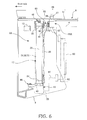
- Fig. 6 is an illustrative view of a radiator according to a modified embodiment.
- the same components as or components similar to the components in the foregoing embodiment are attached with the same reference numerals and their description is omitted.
- the following description will mainly describe its configuration different from the foregoing embodiment.
- a part of the front part of the engine hood 51 serves as the upper plate 15d of the upper main tank 15 in the foregoing embodiment so that the upper main tank 15A is adopted that is configured integrally with the engine hood 51.
- the radiator 5A of this modified embodiment the height of the core units 31 to 33 can be increased by the gap S (see Fig. 4 ) between the upper main tank 15 and the engine hood 51 in the foregoing embodiment. For this reason as compared with the radiator 5 according to the foregoing embodiment, it is possible to further improve the cooling performance.
- single-flange portions 142 may be used for coupling the upper main tank 15 and the upper auxiliary tank 35.
- the radiator 105 includes a core unit 131 that includes a single radiator core 117 that is interposed between upper and lower auxiliary tanks 135 and 136 that are arranged on the upper and lower sides.
- the core unit 131 is connected to the upper main tank 115 and the lower main tank 116 in proximity to the upper and lower ends.
- the module type radiator according to the present invention has been illustratively applied to the bulldozer.
- the present invention is not limited to this.
- the radiator according to the present invention can be applied to work vehicles such as a hydraulic excavator and a wheel loader.
- a radiator according to the present invention has an effect in that its cooling performance can be effectively improved without increasing the entire size of the radiator. For this reason, the radiator according to the present invention can be widely applied to radiators that are installed not only in work vehicles such as construction equipments but also in various types of machines.
Landscapes
- Engineering & Computer Science (AREA)
- Mechanical Engineering (AREA)
- General Engineering & Computer Science (AREA)
- Physics & Mathematics (AREA)
- Thermal Sciences (AREA)
- Chemical & Material Sciences (AREA)
- Combustion & Propulsion (AREA)
- Cooling, Air Intake And Gas Exhaust, And Fuel Tank Arrangements In Propulsion Units (AREA)
- Details Of Heat-Exchange And Heat-Transfer (AREA)
- Transformer Cooling (AREA)
- Heat-Exchange Devices With Radiators And Conduit Assemblies (AREA)
Abstract
Description
- The present invention relates to a radiator including a radiator core.
- A conventional work vehicle such as bulldozer is equipped with a module type radiator that is divided into a plurality of core units so that if the radiator core is partially damaged by vibration, shock and the like the damaged part can be simply replaced. As for this type of radiator, for example,
Patent Document 1 discloses a radiator that facilitates reduction of space for replacing its core unit, simplification of replacing its core unit, and the like. -
Patent Document 1 disclosesmodule type radiators Figs. 8(a) and 8(b) . Themodule type radiators Figs. 8(a) and 8(b) , respectively, have the same basic configuration. Therefore, each of elements having a same function is respectively attached with the same reference numerals in these Figures. - Each of the
radiators Figs. 8(a) and 8(b) , respectively, includes upper and lowermain tanks core units 106, each of which includes upper and lowerauxiliary tanks heat exchanging portion 105 between the upper and lowerauxiliary tanks core units 106 are arranged in parallel to each other on the lowermain tank 102. The uppermain tank 101 is arranged in a position that is offset toward the vehicle front side relative to the lowermain tank 102 in the plan view. In theradiators Figs. 8(a) and 8(b) , respectively, since the uppermain tank 101 is arranged in the offset position relative to the lowermain tank 102 in the plan view, thecore units 106 can be removed/inserted from directly above. For this reason, it is possible to facilitate reduction of space for replacing the core unit, simplification of the replacement, and the like. - In this case, in the
radiators Figs. 8(a) and 8(b) , respectively, the upperauxiliary tank 103 in thecore unit 106 is arranged at a position lower than the uppermain tank 101. In theradiator 100 shown inFig. 8(a) , the upper surface of the upperauxiliary tank 103 and the side surface of the uppermain tank 101 are connected to each other by a coolantwater conduit pipe 107. In theradiator 100A shown inFig. 8(b) , the side surface of the upperauxiliary tank 103 and the lower surface of the uppermain tank 101 are connected by a coolantwater conduit pipe 107A. - On the other hand, recently, in work vehicles such as bulldozer, improvement in cooling performance of radiator is strongly required. In terms of arrangement relationship with peripheral equipments, core airflow resistance and the like, it is conceivable that the best way for improving cooling performance is to increase the height of its core unit (the height of the heat exchanging portion). In the case where the height of the core unit is increased, if the entire height of the radiator is increased, the engine compartment height will be increased. This may adversely affect frontward visibility. For this reason, it is necessary to increase the height of the core unit without increasing the entire height of the radiator in a result.
- However, the
radiators Figs. 8(a) and 8(b) , respectively, arrangement space for the uppermain tank 101 is required above thecore unit 106. For this reason, only increasing the entire height of theradiator 100 can increase the height of thecore unit 106. Accordingly, from the viewpoint of the aforementioned frontward visibility issue, there is a problem in that the height of thecore unit 106 cannot be increased. - Even in the case where radiators include a core unit having the same size, if air bubbles in coolant water are circulated in the cooling pipe path formed in a radiator, cooling efficiency of the radiator may be reduced by circulation of air bubbles. For this reason, even if the height of core units in a radiator could be increased as high as possible, it is very important to prevent circulation of air bubbles contained in coolant water in terms of ensuring the cooling performance of the radiator.
- Patent Document 1: International Publication Pamphlet
W02005/008162 - The present invention is aimed at solving the above mentioned problems. It is an object of the present invention is to provide a radiator capable of effectively improving the cooling performance without increasing the entire size of the radiator.
A radiator according to a first aspect of the present invention includes a heat exchanger, an upper auxiliary tank, a lower auxiliary tank, an upper main tank, and a lower main tank. The upper auxiliary tank is mounted on the upper surface of the heat exchanger. The lower auxiliary tank is mounted on the lower surface of the heat exchanger so that the heat exchanger is interposed between the lower auxiliary tank and the upper auxiliary tank. The upper main tank is arranged at the substantially same height as the upper auxiliary tank, and is connected to the upper auxiliary tank via a coolant water conduit pipe. The upper main tank has a coolant water inlet on the lower surface the upper main tank. The lower main tank is arranged under the upper main tank at an offset position relative to the upper main tank in the plan view. The lower main tank is connected to the lower auxiliary tank. - The coolant water inlet for feeding coolant water into the upper main tank is thus arranged in the lower part of the upper main tank so that the coolant water is fed from the bottom of the upper main tank. Therefore, it is possible to effectively prevent that air enters the coolant water, and to effectively prevent reduction of the cooling performance of the radiator.
In addition, since the upper main tank is arranged at the substantially same height as the upper auxiliary tank, and the upper main tank and the upper auxiliary tank are connected to each other via the coolant water conduit pipe, piping space is not required that has been required above each upper auxiliary tank in the past. For this reason, even in the case where the radiator according to the present invention has the same entire height as the known module type radiator, the height of its core unit can be greater. Therefore, it is possible to improve the cooling performance. - In the radiator according to a second aspect of the present invention, in the radiator according to the first aspect of the present invention, the lower surface of the upper main tank is arranged at the substantially same height as the lower surface of the upper auxiliary tank. In addition to this, the upper surface of the upper main tank is arranged at a higher position than the upper surface of the upper auxiliary tank.
Thus, even in the case where the upper main tank and the upper auxiliary tank are arranged at the substantially same height, since the upper surface of the upper main tank is arranged higher than the upper surface of the upper auxiliary tank, air bubbles contained in the coolant water that flowed into the upper main tank remain on the upper main tank side. Therefore, it is possible to effectively prevent that coolant water containing air bubbles circulates from the upper main tank toward the upper auxiliary tank. - In the radiator according to a third aspect of the present invention, in the radiator according to the first or second aspect of the present invention, the upper main tank has a coolant water outlet that discharges coolant water in the upper auxiliary tank via the coolant water conduit pipe. In addition to this, the upper main tank further includes a baffle that is arranged in proximity to the coolant water outlet to suppress passage of air bubbles through the coolant water outlet.
Thus, it is easily possible to suppress circulation of coolant water that contains air bubbles by means of the baffle that is arranged in the upper main tank. Accordingly, it is possible to suppress that coolant water that contains air bubbles flows from the upper main tank into the upper auxiliary tank. Therefore, it is possible to prevent reduction of the cooling efficiency of the heat exchanger. - In the radiator according to a fourth aspect of the present invention, in the radiator according to the first or second aspect of the present invention, the upper main tank is arranged at an offset position toward an engine side relative to the lower main tank.
Accordingly, coolant water that is warmed in an engine can flow into the upper main tank, which is arranged in proximity to the engine. For this reason, the length of the coolant water conduit pipe can be minimized, and the height of the heat exchanger can be greater. Therefore, it is possible to improve the cooling efficiency and to provide efficient arrangement of components in the engine compartment. - In the radiator according to a fifth aspect of the present invention, in the radiator according to the first or second aspect of the present invention, the radiator includes a plurality of core units, each of which includes the heat exchanger, the upper auxiliary tank and the lower auxiliary tank so that the radiator is configured in a module.
Accordingly, even when one core unit of the plurality of modularized core units is replaced due to malfunction, since the upper main tank is arranged at the offset position in the plan view relative to the lower main tank, the core unit can be removed/inserted from directly above. Therefore, it is possible to facilitate reduction of space for replacing the core unit, simplification of the replacement, and the like. - A radiator according to a sixth aspect of the present invention includes a heat exchanger, an upper auxiliary tank, a lower auxiliary tank, an upper main tank, and a lower main tank. The upper auxiliary tank is mounted on the upper surface of the heat exchanger. The lower auxiliary tank is mounted on the lower surface of the heat exchanger so that the heat exchanger is interposed between the lower auxiliary tank and the upper auxiliary tank. The upper main tank is arranged at the substantially same height as said upper auxiliary tank. The side surface of the upper main tank is connected to the side surface of the upper auxiliary tank via a coolant water conduit pipe. The lower main tank is arranged under the upper main tank at an offset position relative to the upper main tank in the plan view. The lower main tank is connected to the lower auxiliary tank.
- Thus, piping space is unnecessary that has been required above each upper auxiliary tank in the past. For this reason, even in the case where the radiator according to the present invention has the same entire height as the known radiator, the height of its core unit can be greater. As a result, it is possible to improve the cooling performance of the radiator.
- In the radiator according to a seventh aspect of the present invention, in the radiator according to the sixth aspect of the present invention, the radiator includes a plurality of core units, each of which includes the heat exchanger, the upper auxiliary tank and the lower auxiliary tank so that the radiator is configured in a module.
Accordingly, even when one of core unit among the plurality of modularized core units is replaced due to malfunction, since the upper main tank is arranged at the offset position in the plan view relative to the lower main tank, the core unit can be removed/inserted from directly above. Therefore, it is possible to facilitate reduction of space for replacing the core unit, simplification of the replacement, and the like. - In the radiator according to an eighth aspect of the present invention, in the radiator according to the sixth or seventh aspect of the present invention, the coolant water conduit pipe is a straight pipe.
Since a straight pipe is provided as the coolant water conduit pipe that connects the side surface of the upper auxiliary tank in the core unit and the side surface of the upper main tank to each other, the height of the core unit can be maximized even in the case where the thus-configured radiator has the same height as the known radiator. - In the radiator according to a ninth aspect of the present invention, in the radiator according to the sixth or seventh aspect of the present invention, the radiator is installed in a vehicle. In addition to this, the upper main tank is mounted to a vehicle body frame that composes the frame of the vehicle.
In the case where this module type radiator is installed in a vehicle, since the upper main tank is thus mounted to a vehicle body frame that composes the frame of the vehicle, it is possible to firmly keep the arrangement of the upper main tank. - In the radiator according to a tenth aspect of the present invention, in the radiator according to the sixth or seventh aspect of the present invention, the radiator is accommodated in an engine compartment of a vehicle. In addition to this, the upper main tank is configured integrally with an exterior cover that composes the roof of the engine compartment.
In the case where radiators are accommodated in an engine compartment of a vehicle, it is generally necessary to arrange a gap between an exterior cover that composes the roof of the engine compartment, and an upper main tank. However, according to the present invention, since the upper main tank is configured integrally with the exterior cover, it is possible to further increase the height of core unit corresponding to the gap. Therefore, it is possible to further improve the cooling performance of the radiator. -
-
Fig. 1 is a schematic side view of a bulldozer equipped with a module type radiator according to one embodiment of the present invention. -
Fig. 2 is a plan view of the radiator according to this embodiment in an installation state. -
Fig. 3 is a front view of the radiator according to this embodiment in the installation state. -
Fig. 4 is a side view of the radiator according to this embodiment in the installation state. -
Fig. 5 is a cross-sectional view showing an internal configuration of an upper main tank included in the radiator according to this embodiment. -
Fig. 6 is an illustrative view of a radiator according to a modified embodiment. -
Fig. 7 is an illustrative view showing the configuration of a modified radiator according to another embodiment of the present invention. -
Fig. 8 is an illustrative view showing a known radiator. -
- 1
- Bulldozer
- 4
- Engine
- 5, 5a
- Radiator
- 6
- Engine Compartment
- 9
- Vehicle Body Frame
- 15
- Upper Main Tank
- 16
- Lower Main Tank
- 17
- Radiator Core
- 20
- Coolant Water Inlet (Upper Main Tank)
- 21-23
- Coolant Water Outlet
- 31-33
- Core Unit
- 35
- Upper Auxiliary Tank
- 36
- Lower Auxiliary Tank
- 39
- Heat Exchanging Portion (Heat Exchanger)
- 40
- Coolant Water Inlet (Upper Auxiliary Tank)
- 41
- Coolant Water Inlet Reinforcing Plate
- 42
- Rubber Hose
- 50
- Exterior Cover
- 51
- Engine Hood
- 52
- Radiator Hood
- 55
- Baffle Device (Baffle)
- 56
- Upper Convex Bending Plate
- 57
- End Wall Plate
- 58
- Partitioned Chamber
- 60
- Coolant Water Conduit Pipe
- 61
- Water Path
- 62
- Water Pump
- 63
- Water Jacket
- 64
- Thermostat
- The following description will describe a module type radiator according to an exemplary embodiment of the present invention with reference to drawings.
Fig. 1 is a schematic side view of a bulldozer equipped with a module type radiator according to one embodiment of the present invention. Frontward, rearward, rightward and leftward in the following description refer to frontward, rearward, rightward and leftward of the bulldozer. - In the
bulldozer 1 shown inFig. 1 , anengine compartment 6 is disposed in a front part of avehicle body unit 3 that includes track-type drive units 2. Theengine compartment 6 accommodates anengine 4 and amodule type radiator 5. Anoperator compartment 7 is disposed in a rear part of thevehicle body unit 3. Also, ablade 8 is disposed in front of thevehicle body unit 3. Thisblade 8 is moved upward and downward by left and right lift cylinders (only left cylinder is shown) 10 mounted on thevehicle body frame 9. -
Figs. 2 ,3 and4 are plan, front and side views of the radiator according to this embodiment in an installation state, respectively.
As shown inFig. 2 , theradiator 5 is arranged between areinforcement member 12 and theengine 4. Thereinforcement member 12 connects right and left supportingdevices 11 to each other that support the right and left lift cylinders 10 (seeFig. 1 ). Theradiator 5 includes upper and lowermain tanks radiator core 17, and aradiator frame 18, as shown inFig. 3 . The upper and lowermain tanks radiator 5. Theradiator core 17 is arranged on the lowermain tank 16. Theradiator frame 18 is formed in a frame shape that encloses theradiator core 17. Theradiator core 17 is supported by theradiator frame 18 and the lowermain tank 16. - The upper
main tank 15 has a rectangular parallelepiped shape. The uppermain tank 15 is spaced at a certain interval rearwards away from theradiator core 17, and is thus arranged at an offset position relative to the lowermain tank 16 in the plan view. Specifically, the uppermain tank 15 is arranged at an offset position toward anengine 4 side relative to the lowermain tank 16. For this reason, a short pipe can be used for piping of coolant water that flows from theengine 4. Abottom plate 15a composes the lower surface of the uppermain tank 15, and has acoolant water inlet 20 that extends downward. Thiscoolant water inlet 20 is connected to awater jacket 63 of theengine 4 via a coolant water path (piping means) 61. The coolant water from theengine 4 flows into the uppermain tank 15 through thecoolant water inlet 20. Since the coolant water thus flows into the uppermain tank 15 through thecoolant water inlet 20 that is arranged on thebottom plate 15a of the uppermain tank 15, the coolant water is fed from the bottom of the uppermain tank 15. Accordingly, it is possible to prevent that the coolant water contains air. - As shown in
Fig. 2 , afront plate 15b composes the front surface of the uppermain tank 15, and has first and secondcoolant water outlets Fig. 3 , aright side plate 15c composes the right side surface of the uppermain tank 15, and has a thirdcoolant water outlet 23 that extends straightly rightward.
Also, a radiatorcap attachment port 24 is arranged on anupper plate 15d of the uppermain tank 15. A pressurizingradiator cap 25 with a ventilation valve is attached to the radiatorcap attachment port 24. The base part of the radiatorcap attachment port 24 is connected to a reservoir tank (not shown). Thus, the pressure in theradiator 5 is kept constant by theradiator cap 25. The coolant water flows between the uppermain tank 15 and the reservoir tank in the pressurization byradiator cap 25 so that a required amount of coolant water is constantly hold in theradiator 5. As for air that collects in the interior upper part of the uppermain tank 15, the collecting gas is discharged to outside air by operation of the ventilation valve of theradiator cap 25.Reference numerals water feed port 27 is arranged on the upper surface of the uppermain tank 15. Thus, the default water level in the coolantwater feed port 27 is located higher than the uppermain tank 15. - As shown in
Figs. 5(a) and 5(b) , baffle devices (baffles) 55 are arranged correspondingly to coolant water outlets (outlets) 21 to 23 inside the uppermain tank 15. Here, thebaffle device 55 corresponding to the secondcoolant water outlet 22 is illustratively described. Thebaffle device 55 is spaced at a small gap t away from the bottom surface of the uppermain tank 15, as shown inFig. 5(b) . The uppermain tank 15 has partitionedchambers 58. Each of the partitionedchambers 58 is partitioned byfront plate 15b, a sectionally arch-shaped upwardconvex plate 56 and anend wall plate 57, and is opened only downward and toward the secondcoolant water outlet 22 side. Thebaffle device 55 is configured so that the coolant water in the uppermain tank 15 flows from the gap t into the secondcoolant water outlet 22 through the partitionedchamber 58 as shown by an arrow Q inFig. 5(b) . According to this embodiment, since the thus-configuredbaffle device 55 is arranged in the uppermain tank 15, as for air bubbles that are entrained in the coolant water that flows into the uppermain tank 15, it is possible to avoid feeding such air bubbles from the interior of the uppermain tank 15 to the downstream side. Therefore, it is possible to more effectively prevent cooling performance degradation of the radiator due to circulation of the air bubbles that are entrained in the coolant water. - Similar to the upper
main tank 15, the lowermain tank 16 has a rectangular parallelepiped shape. Thecoolant water outlet 28 is arranged on arear plate 16a. As shown inFig. 4 , thecoolant water outlet 28 is connected to thewater jacket 63 of theengine 4 via thecoolant water path 61 and thewater pump 62 so that the coolant water that has been cooled by theradiator core 17 is fed from the lowermain tank 16 into thewater jacket 63 of theengine 4, and is then fed into thecoolant water inlet 20 through athermostat 64. - As shown in
Fig. 4 , the uppermain tank 15 and the lowermain tank 16 are connected to each other by a communicating tube 29 (shown only inFig. 4 for ease of illustration). Accordingly, even if air collects in the lowermain tank 16, the air can be easily moved toward the uppermain tank 15. The air that is moved toward the uppermain tank 15 can be discharged by operation of the ventilation valve of theradiator cap 25. Thus, air in theradiator 5 can be easily removed. Therefore, it is possible to surely prevent air collection in theradiator 5. The communicatingtube 29 is piped not to extend over the exposure surface of theradiator core 17 so that cooling air flow for theradiator core 17 is not be interrupted. - The
radiator core 17 is composed of first, second andthird core units main tank 16 in parallel to each other from the left side to the right side as shown inFig. 3 . Each of thecore units 31 to 33 includes upper and lowerauxiliary tanks auxiliary tanks heat exchanging portion 39 includes a plurality oftubes 37 and radiatingfins 38. The plurality oftubes 37 couple theauxiliary tanks fins 38 are arranged around thetubes 37. The coolant water in the upperauxiliary tank 35 is cooled by air that passes through the radiatingfins 38 when flowing toward thelower auxiliary tank 36 through thetubes 37. As shown inFigs. 3 and4 , the upperauxiliary tank 35 in each of thecore units 31 to 33 is arranged at the substantially same height as the uppermain tank 15. As for the positional relationship from directly above between the upperauxiliary tank 35 and the uppermain tank 15, with reference to the front view inFig. 3 and the side view inFig. 4 , the lower surfaces of the upperauxiliary tank 35 and the uppermain tank 15 are arranged at the substantially same height as each other, and the upper surface of the uppermain tank 15 is arranged higher than the upper surface of the upperauxiliary tank 35. This positional relationship allows the upperauxiliary tank 35 and the uppermain tank 15 to vertically overlap each other in the front view, and additionally ensures the head pressure for the coolant water. Coolant water inlets 40 (discussed later), and thecoolant water outlets - As shown in
Fig. 2 , arear plate 35a composes the rear surface of each upperauxiliary tank 35, and has acoolant water inlet 40 that extends straightly rearward. Thecoolant water inlets 40, and thecoolant water outlets inlet reinforcing plate 41 is mounted on the outer periphery of thecoolant water inlet 40. The coolant waterinlet reinforcing plate 41 is fixed on theradiator frame 18. Thecoolant water inlets 40 of the first, second andthird core units coolant water outlets rubber hoses 42. Thus, the coolant water in the uppermain tank 15 is distributed to thecore units 31 to 33. Each of thecoolant water outlets rubber hose 42, and the correspondingcoolant water inlet 40 are straightly connected to each other so that therubber hose 42 is connected as a straight pipe without being bent. - As shown in
Fig. 3 , a lower maintank coupling port 43 is arranged on a bottom plate of eachlower auxiliary tank 36, and extends downward. The lower maintank coupling ports 43 are detachably coupled to intakes (not shown) that are formed on the lowermain tank 16.
As shown inFig. 2 , theradiator frame 18 is pivotably mounted to thevehicle body frame 9 by a pair of supportingshafts 18a that are arranged on the upper ends of theradiator frame 18 on both the right and left sides. Thecore units 31 to 33 are secured to theradiator frame 18 by rubbermount supporting devices 45 that are arranged above thecore units 31 to 33. As shown inFig. 4 , the lowermain tank 16 is secured to thevehicle body frame 9 by rubbermount supporting devices 46 that are arranged in front of the lowermain tank 16. Thus, it is possible to firmly keep the arrangement of theradiator core 17 and the lowermain tank 16 relative to thevehicle body frame 9, and to prevent that vibration and shock from thevehicle body frame 9 side are directly applied to theradiator core 17 and the lowermain tank 16. - As shown in
Figs. 2 and3 , the uppermain tank 15 is secured to thevehicle body frame 9 by rubbermount supporting devices 47 that are arranged on the right and left sides of the uppermain tank 15. Thus, it is possible to firmly keep the arrangement of the uppermain tank 15 relative to thevehicle body frame 9, and to prevent that vibration and shock from thevehicle body frame 9 side are directly applied to the uppermain tank 15. - As shown in
Fig. 4 , anexterior cover 50 composes the roof of theengine compartment 6, and includes anengine hood 51 and aradiator hood 52. Theengine hood 51 mainly covers theengine 4. Theradiator hood 52 mainly covers theradiator 5. The uppermain tank 15 is arranged at a position in the front-and-rear direction where the rear end portion of theradiator hood 52 overlaps theengine hood 51, and at a position from directly above that is spaced at a certain gap S away from theengine hood 51. - In the radiator according to this embodiment, as shown in
Figs. 3 and4 , the upperauxiliary tank 35 in each of thecore units 31 to 33 is arranged at the substantially same height as the uppermain tank 15. Also, thecoolant water inlet 40 of the upperauxiliary tank 35 in each of thecore units 31 to 33 is arranged at the substantially same height as thecoolant water outlets 21 to 23 of the uppermain tank 15. As shown inFig. 2 , thecoolant water inlets 40 are connected to thecoolant water outlets 21 to 23 via therubber hoses 42. Accordingly, piping space between the uppermain tank 15 and the upperauxiliary tanks 35 can be unnecessary that is required above the upperauxiliary tank 35 in the known radiator. Also, the uppermain tank 15 is spaced away from thecore units 31 to 33 not to overlap thecore units 31 to 33 in the plan view. This arrangement can prevent that the coolant water conduit pipe from theengine 4 to the uppermain tank 15 is arranged above the upperauxiliary tanks 35. For this reason, even in the case where the radiator according to the present invention has the same entire height as the knownmodule type radiators core units 31 to 33 can be greater. Therefore, it is possible to improve the cooling performance of theradiator 5. - The "coolant water conduit pipe" in the present invention corresponds each of the coolant
water conduit pipes 60 that include thecoolant water outlets coolant water inlets 40, and therubber hoses 42.
Also, since thecoolant water inlet 20 for feeding coolant water into the uppermain tank 15 is arranged in the lower surface of the uppermain tank 15, the coolant water is fed from the bottom of the uppermain tank 15. Therefore, it is possible to effectively prevent air entrainment into the coolant water, and to effectively prevent degradation of the cooling performance of theradiator 5. -
Fig. 6 is an illustrative view of a radiator according to a modified embodiment. In this modified embodiment, the same components as or components similar to the components in the foregoing embodiment are attached with the same reference numerals and their description is omitted. The following description will mainly describe its configuration different from the foregoing embodiment.
In this modified embodiment, a part of the front part of theengine hood 51 serves as theupper plate 15d of the uppermain tank 15 in the foregoing embodiment so that the uppermain tank 15A is adopted that is configured integrally with theengine hood 51. According to theradiator 5A of this modified embodiment, the height of thecore units 31 to 33 can be increased by the gap S (seeFig. 4 ) between the uppermain tank 15 and theengine hood 51 in the foregoing embodiment. For this reason as compared with theradiator 5 according to the foregoing embodiment, it is possible to further improve the cooling performance. - In addition, as shown in
Fig. 6 , single-flange portions 142 may be used for coupling the uppermain tank 15 and the upperauxiliary tank 35.
The radiators according to the embodiment and its modified embodiment have been described. However, the present invention is not limited to the configurations described in the embodiment and its modified embodiment. Various changes and modifications can be made without departing from the spirit of the present invention. - For example, as shown in
Fig. 7 , the present invention can be also applied not to the module type radiator but to aunitary type radiator 105. Theradiator 105 includes acore unit 131 that includes asingle radiator core 117 that is interposed between upper and lowerauxiliary tanks core unit 131 is connected to the uppermain tank 115 and the lowermain tank 116 in proximity to the upper and lower ends. - In the foregoing embodiment and its modified embodiment, the module type radiator according to the present invention has been illustratively applied to the bulldozer. However, the present invention is not limited to this. Needless to say, the radiator according to the present invention can be applied to work vehicles such as a hydraulic excavator and a wheel loader.
- A radiator according to the present invention has an effect in that its cooling performance can be effectively improved without increasing the entire size of the radiator. For this reason, the radiator according to the present invention can be widely applied to radiators that are installed not only in work vehicles such as construction equipments but also in various types of machines.
Claims (10)
- A radiator comprising:a heat exchanger;an upper auxiliary tank that is mounted on the upper surface of said heat exchanger;a lower auxiliary tank that is mounted on the lower surface of said heat exchanger so that said heat exchanger is interposed between the lower auxiliary tank and said upper auxiliary tank;an upper main tank that is arranged at the substantially same height as said upper auxiliary tank and is connected to said upper auxiliary tank via a coolant water conduit pipe, the upper main tank having a coolant water inlet on the lower surface thereof; anda lower main tank that is arranged under said upper main tank at an offset position relative to said upper main tank in the plan view, the lower main tank being connected to said lower auxiliary tank.
- The radiator according to claim 1, wherein the lower surface of said upper main tank is arranged at the substantially same height as the lower surface of said upper auxiliary tank, and the upper surface of said upper main tank is arranged at a higher position than the upper surface of said upper auxiliary tank.
- The radiator according to claim 1 or 2, wherein said upper main tank has a coolant water outlet that discharges coolant water via said coolant water conduit pipe, and said upper main tank further includes a baffle that is arranged in proximity to said coolant water outlet to suppress passage of air bubbles through said coolant water outlet.
- The radiator according to claim 1 or 2, wherein said upper main tank is arranged at an offset position toward an engine side relative to said lower main tank.
- The radiator according to claim 1 or 2, wherein the radiator includes a plurality of core units, each of which includes said heat exchanger, said upper auxiliary tank and said lower auxiliary tank so that the radiator is configured in a module.
- A radiator comprising:a heat exchanger;an upper auxiliary tank that is mounted on the upper surface of said heat exchanger;a lower auxiliary tank that is mounted on the lower surface of said heat exchanger so that said heat exchanger is interposed between the lower auxiliary tank and said upper auxiliary tank;an upper main tank that is arranged at the substantially same height as said upper auxiliary tank, the side surface of the upper main tank being connected to the side surface of said upper auxiliary tank via a coolant water conduit pipe; anda lower main tank that is arranged under said upper main tank at an offset position relative to said upper main tank in the plan view, the lower main tank being connected to said lower auxiliary tank.
- The radiator according to claim 6, wherein the radiator includes a plurality of core units, each of which includes said heat exchanger, said upper auxiliary tank and said lower auxiliary tank so that the radiator is configured in a module.
- The radiator according to claim 6 or 7, wherein said coolant water conduit pipe is a straight pipe.
- The radiator according to claim 6 or 7, wherein the radiator is installed in a vehicle, and said upper main tank is mounted to a vehicle body frame that composes the frame of said vehicle.
- The radiator according to claim 6 or 7, wherein the radiator is accommodated in an engine compartment of a vehicle, and said upper main tank is configured integrally with an exterior cover that composes the roof of said engine compartment.
Applications Claiming Priority (4)
| Application Number | Priority Date | Filing Date | Title |
|---|---|---|---|
| JP2007235476 | 2007-09-11 | ||
| JP2008224133A JP5390811B2 (en) | 2007-09-11 | 2008-09-01 | Radiator |
| JP2008224134A JP5390812B2 (en) | 2007-09-11 | 2008-09-01 | Radiator |
| PCT/JP2008/065967 WO2009034914A1 (en) | 2007-09-11 | 2008-09-04 | Radiator |
Publications (2)
| Publication Number | Publication Date |
|---|---|
| EP2187160A1 true EP2187160A1 (en) | 2010-05-19 |
| EP2187160A4 EP2187160A4 (en) | 2013-03-20 |
Family
ID=40659233
Family Applications (1)
| Application Number | Title | Priority Date | Filing Date |
|---|---|---|---|
| EP08830843A Withdrawn EP2187160A4 (en) | 2007-09-11 | 2008-09-04 | Radiator |
Country Status (5)
| Country | Link |
|---|---|
| US (1) | US20100186925A1 (en) |
| EP (1) | EP2187160A4 (en) |
| JP (2) | JP5390811B2 (en) |
| CN (1) | CN101960249B (en) |
| WO (1) | WO2009034914A1 (en) |
Cited By (1)
| Publication number | Priority date | Publication date | Assignee | Title |
|---|---|---|---|---|
| US20180252148A1 (en) * | 2015-09-08 | 2018-09-06 | Nippon Thermostat Co., Ltd. | Coolant passage device for internal combustion engine |
Families Citing this family (6)
| Publication number | Priority date | Publication date | Assignee | Title |
|---|---|---|---|---|
| US9051709B1 (en) | 2014-02-21 | 2015-06-09 | Komatsu Ltd. | Work vehicle |
| JP2018062733A (en) * | 2015-03-02 | 2018-04-19 | 株式会社小松製作所 | Work vehicle and ripper device |
| JP6327313B2 (en) * | 2016-10-17 | 2018-05-23 | マツダ株式会社 | Engine cooling system |
| JP6770931B2 (en) * | 2017-06-26 | 2020-10-21 | 株式会社クボタ | Harvester |
| CN111520222B (en) * | 2020-04-21 | 2021-12-31 | 扬州贝诺汽车配件有限公司 | Radiator assembly of automobile water tank |
| CN121322179A (en) * | 2024-07-10 | 2026-01-13 | 卡特彼勒公司 | Expansion water tank system, filling method and engineering machinery |
Family Cites Families (16)
| Publication number | Priority date | Publication date | Assignee | Title |
|---|---|---|---|---|
| US2108233A (en) * | 1935-10-23 | 1938-02-15 | Pudlich Carl Wilhelm | Croquette molder |
| US2108223A (en) * | 1935-10-25 | 1938-02-15 | Fred M Young | Air cooling device for compressors |
| US2482626A (en) * | 1944-08-28 | 1949-09-20 | Joy Mfg Co | Compressor |
| DE1128705B (en) * | 1958-12-04 | 1962-04-26 | Sueddeutsche Kuehler Behr | Device for venting the cooling water circuits of internal combustion engines, especially for motor vehicles |
| US3834478A (en) * | 1973-03-28 | 1974-09-10 | Caterpillar Tractor Co | Pivotal guard for a vehicle |
| US3989103A (en) * | 1973-04-19 | 1976-11-02 | White Motor Corporation | Method and apparatus for cooling and deaerating internal combustion engine coolant |
| JPS6243129U (en) * | 1985-09-04 | 1987-03-16 | ||
| JPS6317962U (en) * | 1986-07-21 | 1988-02-05 | ||
| US4741392A (en) * | 1988-02-05 | 1988-05-03 | Modine Manufacturing Company | Sectional core radiator |
| US5465783A (en) * | 1994-03-04 | 1995-11-14 | Fedco Automotive Components Company, Inc. | Sacrificial erosion bridge for a heat exchanger |
| KR100565818B1 (en) * | 1996-08-12 | 2007-04-04 | 칼소닉 칸세이 가부시끼가이샤 | Integral heat exchanger |
| JP2002162178A (en) * | 2000-11-21 | 2002-06-07 | Mitsubishi Heavy Ind Ltd | Heat exchanger and baffle thereof |
| JP2007085560A (en) * | 2004-03-29 | 2007-04-05 | T Rad Co Ltd | Module radiator |
| WO2005108899A1 (en) * | 2004-05-11 | 2005-11-17 | Showa Denko K.K. | Heat exchangers |
| DE102006014400B4 (en) * | 2006-02-02 | 2012-01-26 | Audi Ag | Expansion tank for a cooling system and cooling arrangement |
| CN100470173C (en) * | 2006-07-19 | 2009-03-18 | 南方英特空调有限公司 | Vehicle air conditioner evaporator |
-
2008
- 2008-09-01 JP JP2008224133A patent/JP5390811B2/en not_active Expired - Fee Related
- 2008-09-01 JP JP2008224134A patent/JP5390812B2/en not_active Expired - Fee Related
- 2008-09-04 CN CN2008801066672A patent/CN101960249B/en not_active Expired - Fee Related
- 2008-09-04 WO PCT/JP2008/065967 patent/WO2009034914A1/en not_active Ceased
- 2008-09-04 US US12/668,709 patent/US20100186925A1/en not_active Abandoned
- 2008-09-04 EP EP08830843A patent/EP2187160A4/en not_active Withdrawn
Cited By (2)
| Publication number | Priority date | Publication date | Assignee | Title |
|---|---|---|---|---|
| US20180252148A1 (en) * | 2015-09-08 | 2018-09-06 | Nippon Thermostat Co., Ltd. | Coolant passage device for internal combustion engine |
| US10494987B2 (en) * | 2015-09-08 | 2019-12-03 | Nippon Thermostat Co., Ltd. | Coolant passage device for internal combustion engine |
Also Published As
| Publication number | Publication date |
|---|---|
| JP2009085584A (en) | 2009-04-23 |
| EP2187160A4 (en) | 2013-03-20 |
| WO2009034914A1 (en) | 2009-03-19 |
| CN101960249A (en) | 2011-01-26 |
| JP5390812B2 (en) | 2014-01-15 |
| US20100186925A1 (en) | 2010-07-29 |
| JP2009085585A (en) | 2009-04-23 |
| JP5390811B2 (en) | 2014-01-15 |
| CN101960249B (en) | 2012-07-11 |
Similar Documents
| Publication | Publication Date | Title |
|---|---|---|
| US20100186925A1 (en) | Radiator | |
| US9499957B2 (en) | Bulldozer with improved visibility | |
| US10214247B2 (en) | Work vehicle | |
| CN212979863U (en) | Cooling water comprehensive heat management device for vehicle | |
| US8875823B2 (en) | Multi-functional cooling system | |
| US8800704B2 (en) | Wheel loader | |
| EP2727804A1 (en) | Saddle-type vehicle | |
| EP3663549B1 (en) | Work vehicle | |
| US20080142235A1 (en) | Drilling Unit | |
| US9512773B2 (en) | Cooling apparatus for construction machine | |
| EP1736348B1 (en) | Radiator module for commercial motor vehicles | |
| JP2007283801A (en) | Construction machine | |
| KR20050102045A (en) | Construction machine | |
| CN108026826B (en) | Cooling water passage device in internal combustion engine | |
| JP6552320B2 (en) | Tractor | |
| US20140209405A1 (en) | Saddle ride type vehicle | |
| US7182164B2 (en) | Cooling equipment for a motor vehicle, in particular for an excavator | |
| EP2135798B1 (en) | Agricultural utility vehicle comprising a fluid reservoir | |
| WO2014024323A1 (en) | Bulldozer | |
| JP7173919B2 (en) | work vehicle | |
| CN201573532U (en) | Blocking structure of cooling component in engine compartment and corresponding engine hood device | |
| JP5484967B2 (en) | Construction machinery | |
| JP6530999B2 (en) | Tractor | |
| CN211641827U (en) | Working vehicle | |
| CN212148729U (en) | Working vehicle |
Legal Events
| Date | Code | Title | Description |
|---|---|---|---|
| PUAI | Public reference made under article 153(3) epc to a published international application that has entered the european phase |
Free format text: ORIGINAL CODE: 0009012 |
|
| 17P | Request for examination filed |
Effective date: 20100126 |
|
| AK | Designated contracting states |
Kind code of ref document: A1 Designated state(s): AT BE BG CH CY CZ DE DK EE ES FI FR GB GR HR HU IE IS IT LI LT LU LV MC MT NL NO PL PT RO SE SI SK TR |
|
| AX | Request for extension of the european patent |
Extension state: AL BA MK RS |
|
| DAX | Request for extension of the european patent (deleted) | ||
| A4 | Supplementary search report drawn up and despatched |
Effective date: 20130214 |
|
| RIC1 | Information provided on ipc code assigned before grant |
Ipc: F28F 9/26 20060101AFI20130208BHEP Ipc: F01P 3/18 20060101ALI20130208BHEP Ipc: F01P 11/02 20060101ALI20130208BHEP Ipc: F28F 9/02 20060101ALI20130208BHEP Ipc: F28F 9/00 20060101ALI20130208BHEP |
|
| 17Q | First examination report despatched |
Effective date: 20140103 |
|
| GRAP | Despatch of communication of intention to grant a patent |
Free format text: ORIGINAL CODE: EPIDOSNIGR1 |
|
| INTG | Intention to grant announced |
Effective date: 20140220 |
|
| STAA | Information on the status of an ep patent application or granted ep patent |
Free format text: STATUS: THE APPLICATION IS DEEMED TO BE WITHDRAWN |
|
| 18D | Application deemed to be withdrawn |
Effective date: 20140624 |