EP2187123A2 - Bladed coal diffuser and coal line balancing device - Google Patents
Bladed coal diffuser and coal line balancing device Download PDFInfo
- Publication number
- EP2187123A2 EP2187123A2 EP09175983A EP09175983A EP2187123A2 EP 2187123 A2 EP2187123 A2 EP 2187123A2 EP 09175983 A EP09175983 A EP 09175983A EP 09175983 A EP09175983 A EP 09175983A EP 2187123 A2 EP2187123 A2 EP 2187123A2
- Authority
- EP
- European Patent Office
- Prior art keywords
- coal
- diffuser
- assembly
- blades
- upstream
- Prior art date
- Legal status (The legal status is an assumption and is not a legal conclusion. Google has not performed a legal analysis and makes no representation as to the accuracy of the status listed.)
- Granted
Links
- 239000003245 coal Substances 0.000 title claims abstract description 150
- 238000011144 upstream manufacturing Methods 0.000 claims description 50
- 229910010293 ceramic material Inorganic materials 0.000 claims description 4
- 230000008859 change Effects 0.000 claims description 2
- 239000000446 fuel Substances 0.000 abstract description 28
- MWUXSHHQAYIFBG-UHFFFAOYSA-N Nitric oxide Chemical compound O=[N] MWUXSHHQAYIFBG-UHFFFAOYSA-N 0.000 description 60
- 238000002485 combustion reaction Methods 0.000 description 16
- 239000002245 particle Substances 0.000 description 10
- 239000000919 ceramic Substances 0.000 description 7
- 238000009826 distribution Methods 0.000 description 6
- 230000008901 benefit Effects 0.000 description 5
- 230000003628 erosive effect Effects 0.000 description 4
- 230000004907 flux Effects 0.000 description 4
- 238000009434 installation Methods 0.000 description 4
- 230000001965 increasing effect Effects 0.000 description 3
- 238000012360 testing method Methods 0.000 description 3
- 230000015572 biosynthetic process Effects 0.000 description 2
- 239000012530 fluid Substances 0.000 description 2
- 238000012986 modification Methods 0.000 description 2
- 230000004048 modification Effects 0.000 description 2
- 238000009987 spinning Methods 0.000 description 2
- UGFAIRIUMAVXCW-UHFFFAOYSA-N Carbon monoxide Chemical compound [O+]#[C-] UGFAIRIUMAVXCW-UHFFFAOYSA-N 0.000 description 1
- 230000001133 acceleration Effects 0.000 description 1
- 230000004075 alteration Effects 0.000 description 1
- 230000004888 barrier function Effects 0.000 description 1
- 239000002802 bituminous coal Substances 0.000 description 1
- 230000015556 catabolic process Effects 0.000 description 1
- 239000002817 coal dust Substances 0.000 description 1
- 230000003750 conditioning effect Effects 0.000 description 1
- 230000007797 corrosion Effects 0.000 description 1
- 238000005260 corrosion Methods 0.000 description 1
- 230000007423 decrease Effects 0.000 description 1
- 238000006731 degradation reaction Methods 0.000 description 1
- 230000003292 diminished effect Effects 0.000 description 1
- 230000000694 effects Effects 0.000 description 1
- 230000002708 enhancing effect Effects 0.000 description 1
- 239000003546 flue gas Substances 0.000 description 1
- 239000012634 fragment Substances 0.000 description 1
- 230000000977 initiatory effect Effects 0.000 description 1
- 238000007689 inspection Methods 0.000 description 1
- 239000000463 material Substances 0.000 description 1
- 230000007246 mechanism Effects 0.000 description 1
- 239000002184 metal Substances 0.000 description 1
- 238000000034 method Methods 0.000 description 1
- 230000000116 mitigating effect Effects 0.000 description 1
- 239000000203 mixture Substances 0.000 description 1
- 238000009828 non-uniform distribution Methods 0.000 description 1
- 238000010248 power generation Methods 0.000 description 1
- 230000001737 promoting effect Effects 0.000 description 1
- 230000009467 reduction Effects 0.000 description 1
- 238000012546 transfer Methods 0.000 description 1
- 238000009827 uniform distribution Methods 0.000 description 1
Images


Classifications
-
- F—MECHANICAL ENGINEERING; LIGHTING; HEATING; WEAPONS; BLASTING
- F23—COMBUSTION APPARATUS; COMBUSTION PROCESSES
- F23D—BURNERS
- F23D1/00—Burners for combustion of pulverulent fuel
-
- F—MECHANICAL ENGINEERING; LIGHTING; HEATING; WEAPONS; BLASTING
- F23—COMBUSTION APPARATUS; COMBUSTION PROCESSES
- F23K—FEEDING FUEL TO COMBUSTION APPARATUS
- F23K3/00—Feeding or distributing of lump or pulverulent fuel to combustion apparatus
- F23K3/02—Pneumatic feeding arrangements, i.e. by air blast
-
- F—MECHANICAL ENGINEERING; LIGHTING; HEATING; WEAPONS; BLASTING
- F23—COMBUSTION APPARATUS; COMBUSTION PROCESSES
- F23D—BURNERS
- F23D2201/00—Burners adapted for particulate solid or pulverulent fuels
- F23D2201/10—Nozzle tips
-
- F—MECHANICAL ENGINEERING; LIGHTING; HEATING; WEAPONS; BLASTING
- F23—COMBUSTION APPARATUS; COMBUSTION PROCESSES
- F23D—BURNERS
- F23D2201/00—Burners adapted for particulate solid or pulverulent fuels
- F23D2201/20—Fuel flow guiding devices
-
- F—MECHANICAL ENGINEERING; LIGHTING; HEATING; WEAPONS; BLASTING
- F23—COMBUSTION APPARATUS; COMBUSTION PROCESSES
- F23D—BURNERS
- F23D2202/00—Liquid fuel burners
-
- F—MECHANICAL ENGINEERING; LIGHTING; HEATING; WEAPONS; BLASTING
- F23—COMBUSTION APPARATUS; COMBUSTION PROCESSES
- F23D—BURNERS
- F23D2900/00—Special features of, or arrangements for burners using fluid fuels or solid fuels suspended in a carrier gas
- F23D2900/00018—Means for protecting parts of the burner, e.g. ceramic lining outside of the flame tube
-
- Y—GENERAL TAGGING OF NEW TECHNOLOGICAL DEVELOPMENTS; GENERAL TAGGING OF CROSS-SECTIONAL TECHNOLOGIES SPANNING OVER SEVERAL SECTIONS OF THE IPC; TECHNICAL SUBJECTS COVERED BY FORMER USPC CROSS-REFERENCE ART COLLECTIONS [XRACs] AND DIGESTS
- Y02—TECHNOLOGIES OR APPLICATIONS FOR MITIGATION OR ADAPTATION AGAINST CLIMATE CHANGE
- Y02E—REDUCTION OF GREENHOUSE GAS [GHG] EMISSIONS, RELATED TO ENERGY GENERATION, TRANSMISSION OR DISTRIBUTION
- Y02E20/00—Combustion technologies with mitigation potential
- Y02E20/34—Indirect CO2mitigation, i.e. by acting on non CO2directly related matters of the process, e.g. pre-heating or heat recovery
Definitions
- the present invention concerns improvements in the field of low nitrogen oxide (NOx) pulverized coal fired burners. More particularly, but not exclusively, the invention relates to a coal nozzle assembly that conditions the pulverized coal/primary air stream prior to combustion.
- NOx nitrogen oxide
- Low NOx coal fired burners employ various types of hardware in the burner nozzles to alter the primary air/pulverized coal (PA/PC) stream before entering the burner throat for initiation of combustion. These devices are designed to enhance fuel/air mixing to better control NOx emissions.
- US Patent 4,380,202 discloses a conical diffuser 10 (an example of which is depicted in FIG. 1 ) that has been utilized in Babcock and Wilcox's DRB-XCL® and DRB-4Z® burners.
- the conical diffuser 10 is located near the entrance of the coal nozzle 4 downstream of an optional stationary deflector 8 located within the annuals of coal nozzle 4.
- the diffuser promotes the generation of a fuel rich ring of fuel near the walls of the coal nozzle 4 downstream of the conical diffuser 10, thereby promoting improvements in flame stability and lower NOx emissions.
- the conical diffuser 10 is typically constructed from ceramic materials to improve wear resistance.
- Combustion testing has demonstrated that an air-staged DRB-4Z® burner equipped with a distribution cone 5 located in the coal nozzle 4 and upstream of a standard bladed impeller 12 (see FIG. 2 ) produces lower NOx emissions than the same burner equipped with a conical diffuser.
- Testing with eastern bituminous coal has shown that a NOx reduction of about 17% can be achieved using a standard bladed impeller 12 when staged near 0.8 stoichiometry. Increased near field mixing under reducing conditions tends to favor lower NOx emissions.
- Field testing has also demonstrated lower NOx emissions are achieved with DRB-XCL® burners equipped with standard bladed impellers 12 compared to those equipped with conical diffusers 10 under certain staged conditions.
- standard bladed impellers 12 and similarly located mixing devices can offer functional NOx improvements, they generally suffer from erosion and high temperature related degradation. Achieving the intended mixing benefit of standard bladed impellers 12 generally requires placing the impellers at or near the exit of the burner coal within the coal nozzle 4. However, at these locations impellers readily reach high temperatures from radiative heat transfer from the furnace. These high temperatures are undesirable to impeller longevity as they can thermally erode metal components directly and/or cause coal to stick and cake upon the device causing additional unfavorable consequential damages.
- Pulverized coal is highly abrasive, and erosion from pulverized coal is a consistent problem for burner component in direct contact therewith. While ceramics can minimize this effect and are frequently used to protect equipment from erosion, high temperatures near the exit of the burner coal nozzle 4 prevent the effective use of ceramics in such applications.
- erosion and exposure to high temperatures generally shorten component life of impellers and similarly located devices to typically about a year of effective service life, after which the burner experiences diminished performance until such time that the impeller is replaced.
- Standard impellers 12 and similarly located devices thus experience a limited effective service life in the power generation, requiring substantial expenditures (cost, material, labor, and outage time) to facilitate repeated replacements.
- a need thus exists to develop a diffuser impeller device of a lengthened service life to alleviate concerns associated with prior art impellers.
- An additional concern of pulverized coal fired burners is the potential for nonuniform distribution of pulverized coal and primary air to multiple burners served by a given pulverizer.
- Such non-uniformities are due in part to differences in coal piping from the source (pulverizer) of a pulverized coal stream to each individual coal outlet (burner).
- Each burner as provided within a given boiler/combustion facility, is located at a unique distance from the pulverizer that supplies the pulverized coal to the burner.
- Inherent in any given boiler facility are differences such as: lengths of coal piping runs, number of bends per each run, bend geometries, and in some cases a single mill or pulverizer can supply multiple elevations of burners.
- Adjustable flow resistors provide the advantage of on-line adjustment for measured imbalances, with varying effectiveness.
- such devices are generally economically infeasible based on the need to supply a ceramic lined spool piece to house such a device.
- installation costs provide an additional barrier to feasibility due to the need for coal piping alterations (cutting, addition of flanges), a lack of accessibility, and a need for new platforms etc. to install and maintain such equipment.
- a need thus exists for improved readily installable adjustable flow resistors.
- Effective impeller designs must also take into consideration various characteristics of combustion such as flame length.
- Low NOx pulverized coal-fired burners tend to form long flames and produce higher levels of unburned combustibles relative to conventional burners. Long flames generally result from insufficient air supply to the fuel jet as it proceeds into the furnace. Secondary air from the outer air zones of low NOx burners does not effectively penetrate the fuel jet, such that uncombusted fuel persists along the flame axis.
- Many low NOx systems utilize over-fire air ports to burn out uncombusted fuel in a manner that inhibits NOx emissions via the well known principle of air staging.
- the present invention provides a coal nozzle assembly for a pulverized coal burner, a diffuser that may be used with the assembly, and a flow conditioner that may be used with the assembly.
- the assembly of the present invention conditions the coal/air flow before the coal/air flow exits the burner.
- the invention can provide a ceramic diffuser located in the upstream end of the coal nozzle.
- the configuration of the diffuser allows the diffuser to be manufactured from ceramic and located in the cooler upstream end of the coal nozzle.
- the ceramic diffuser may have a body with a tapered upstream portion and a plurality of blades extending outwardly from the body. The blades are angled with respect to the longitudinal direction of the coal nozzle such that a coal and air flow passing through the diffuser may be selectively swirled.
- the invention can provide a diffuser for a coal nozzle wherein the tapered upstream end of the diffuser body is blunt so that a pulverized coal stream engaging the blunt upstream end of the diffuser will be broken apart and directed relatively evenly between the pluralities of blades.
- the invention can provide a diffuser for a coal nozzle wherein the body of the diffuser includes a tapered upstream end and a downstream portion with blades extending outwardly from both the upstream end and the downstream portion.
- the invention can also provide an adjustable flow conditioner for a burner elbow wherein the flow conditioner includes a fixed portion and an adjustable portion.
- Another configuration of the invention can provide a coal nozzle assembly for a pulverized coal burner.
- the assembly includes a coal nozzle having an upstream inlet and a downstream outlet; the coal nozzle having a wall having an inner surface; a burner elbow disposed upstream of the upstream inlet; a diffuser positioned in the coal nozzle closer to the upstream inlet than the downstream outlet; the diffuser having a body with a tapered upstream portion; the diffuser having a plurality of blades extending outwardly from the body; the blades being adapted to spin a flow of air and coal; and an adjustable flow conditioner carried by the burner elbow; the adjustable flow conditioner having a fixed portion and an moveable portion; the fixed portion being adapted to direct a pulverized coal stream into the tapered upstream portion of the diffuser and the moveable portion being selectively movable to adjust the pressure drop across the burner elbow.
- FIG. 1 is a perspective view of a known coal nozzle assembly having a conical diffuser.
- FIG. 2 is a perspective view of a known coal nozzle assembly having a 15 degree impeller.
- FIGS. 3A-3E are schematic views showing the particle flux of primary air/pulverized coal at locations along the prior art coal nozzle assembly of FIG. 2 .
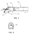
- FIG. 4 is a longitudinal section view of a coal nozzle assembly according to one example configuration.
- FIG. 5 is an end view of the example coal nozzle assembly of FIG. 4 .
- FIG. 6 is a perspective view of an example configuration of a diffuser used with the coal nozzle assembly.
- FIGS. 7A-7E are schematic views showing the particle flux of primary air/pulverized coal at locations along the coal nozzle assembly of FIG. 4 with the adjustable deflector 100 percent open.
- FIGS. 8A-8E are schematic views showing the particle flux of primary air/pulverized coal at locations along the coal nozzle assembly of FIG. 4 with the adjustable deflector 100 percent closed.
- Fig. 9A is a first perspective cross sectional view of a coal deflector wherein the adjustable deflector is in a first position.
- Fig. 9B is a second perspective cross sectional view of a coal deflector wherein the adjustable deflector is in a second position.
- a coal nozzle assembly 102 for a pulverized coal burner includes a coal nozzle or coal nozzle pipe104 and a burner elbow 106.
- Coal nozzle assembly 102 conditions the primary air/pulverized coal stream before dispensing it to the furnace.
- Coal nozzle assembly 102 may be used to accomplish rapid mixing of pulverized coal and secondary air in a burner to accelerate the combustion of the pulverized coal under reducing conditions in an air staged unit.
- the accelerated combustion oxidizes the fuel more rapidly in the burner zone to the extent air is available.
- the accelerated combustion provides more time for the flue gas to complete the combustion under reducing conditions before the balance of air is supplied by the over fire air system.
- the increased residence time under reducing conditions decreases the amount of NOx formed in the burner zone.
- more complete combustion in the burner zone limits the amount of remaining fuel needed to burn at and above the over fire air ports, thereby lowering the unburned combustibles leaving the furnace and improving efficiency. Accelerated combustion is further desirable as it serves to shorten and widen the flame envelope; reducing flame impingement for single wall fired boilers and mitigating the formation of longer flames capable of extending into the over fire air zone.
- Coal nozzle assembly 102 includes a diffuser 110 located in the cooler upstream portion of coal nozzle 104.
- the upstream portion of coal nozzle 104 is readily defined as the ceramic lined portion of the coal nozzle 104, which is generally inclusive of the half of nozzle 104 that is closest to the inlet 112 of nozzle 104.
- diffuser 110 is located one quarter of the nozzle length (defined between inlet end 112 and the outlet end 114) from inlet end 112. In other configurations, diffuser 110 may be located from between about zero to about 2 coal nozzle diameters away from nozzle inlet end 112.
- Diffuser 110 is configured to condition the primary air/pulverized coal stream into an elongated tube having a high concentration of pulverized coal disposed around a primary air-rich center. Once the pulverized coal leaves nozzle 104 at the nozzle exit 114, it will continue to flare in an outward motion causing it to mix with the secondary air streams and increase the rate of combustion.
- the location of diffuser 110 in the nozzle 104 allows diffuser 110 to be fabricated from a ceramic material to provide diffuser 110 with more desirable wear properties.
- Diffuser 110 imparts a spin or a swirl on the primary air/pulverized coal stream in the upstream portion of coal nozzle 104. Diffuser 110 encourages the spinning flow to persist from the location of diffuser 110 to the exit 114 of coal nozzle 104 and into the furnace. Diffuser 110 is configured to generate a downstream fuel configuration that is air rich in the center and fuel rich near the inner surface of the coal nozzle 104. In addition to its location in coal nozzle 104, diffuser 110 achieves the desired fuel/air distribution using a tapered upstream body portion or nose 120 combined with a plurality of blades 122 that extend from a downstream body portion 124. In addition to these factors, the distribution of the fuel and air within coal nozzle 104 is influenced by flow conditioning in elbow 106.
- a flow conditioner 130 may be provided in burner elbow 106 to redirect pulverized coal flow (generally in the form of an elongated stream/helical coil or a "coal rope") formed along the outer radius of elbow 106 by centrifugal forces.
- Flow conditioner 130 may be used to direct the coal rope into upstream body portion 120 of diffuser 110 where the pulverized coal flow is broken apart and distributed directly against blades 122, wherein the fuel is redirected into a swirling pattern that results in the desired fuel distribution pattern.
- diffuser 110 includes a body having an upstream body portion or nose 120 disposed in front of a central downstream body portion 124.
- Nose 120 may blend smoothly or seamlessly into the front of downstream body portion 124 so that there are substantially no interruptions that disrupt the flow of coal and air.
- Nose 120 is tapered from a small upstream end towards a larger downstream end.
- Nose 120 may incorporate different shapes.
- nose 120 is of a semi-spherical or elongated semi-spherical shape wherein the diameter of the sphere is the widest portion of the bullet nose.
- oval, conical, pyramidal and elongated taped oval shapes may be utilized.
- nose 120 defines a portion of a sphere having an outer diameter about one third of the inner diameter of coal nozzle 104.
- the diameter of the bullet nozzle is preferably between about 15 to about 20 percent of the coal nozzle diameter.
- downstream body portion 124 may be in the form of a right-cylinder having an outer diameter substantially equal to the outer diameter of nose 120. Nose 120 and downstream body portion 124 may be integrally formed.
- the downstream end 140 of downstream body portion 124 may taper to a more narrow diameter so as to not create a sharp change that would interfere with the flow of air and fuel.
- the narrowed diameter of downstream end 140 may be between about 100% and 10 percent of the outer diameter of the body portion.
- downstream body portion 124 may be tapered itself with its upstream and downstream ends having smaller diameters than its middle portion so that trunk 124 resembles a barrel.
- a plurality of blades 122 extend outwardly from the body of diffuser 110.
- Blades 122 may be disposed at an angle to the longitudinal direction of coal nozzle 104 (which is generally parallel to the flow direction of the fuel in the cold end of coal nozzle 104) so that a spin or swirl is imparted to the fuel as it moves through diffuser 110.
- Blades 122 are configured to impart an outwardly directed force to the coal particles so that they move toward the inner surface of coal nozzle 104 as they move across blades 122 and after they leave diffuser 110.
- Blades 110 may be angled from zero to forty-five degrees with respect to the longitudinal direction of nozzle 104 when viewed from the front of diffuser 110. Lesser pitch angles are believed to function well with un-staged units, as this reduces the mixing energy with the secondary air to help reduce NOx emissions while still creating an air rich center and fuel rich outer annulus.
- blades 122 Although ten blades 122 are shown in the example configuration of FIG. 6 , different numbers of blades 122 may be used. Other diffuser 110 configurations may have from four to fourteen blades 122. The number of blades 122 enables a degree of control over pressure drop through diffuser 110 and changes the mixing energy of the fuel with the secondary air once the coal particles leave coal nozzle 104. The number of blades 122 and the configuration of blades 122 thus may be adapted for specific applications and specific coal nozzle geometries and designs.
- each blade 122 is the dimension disposed generally along the flow direction.
- the radial length or height 152 of each blade 122 is generally in the radial direction of diffuser 110.
- the upstream end 154 of each blade 122 is tapered (rounded in the example configuration) and the downstream end 156 of each blade 122 is also tapered (also rounded in the example configuration).
- Each blade 122 is angled such that it defines an upstream impingement surface or upstream sidewall 158 that is directly impinged by the fuel flow and a downstream surface or downstream sidewall 160.
- the blade thickness is the distance between sidewalls 158 and 160 at any point of the blade. The thickness may be substantially constant such as when sidewalls 158 and 160 are flat and parallel (as shown in FIG.
- blade thickness may vary when sidewalls 158 and 160 are not parallel such as when the blade is in the form of an airfoil or a tapered thickness blade.
- blade sidewalls 158 and 160 are flat and parallel.
- Blades 122 that are spiraled in shape along the length of downstream body portion 124 may provide an acceleration to the coal particles through diffuser 110 thus increasing their mixing energy with the secondary air as the coal particles leave the coal nozzle.
- Blades 122 in the shape of airfoils may provide a way of creating more spin while not needing an aggressive blade angle to help reduce pressure drop.
- Each blade 122 overlaps a portion of nose 120 such that each upstream end 154 is disposed upstream of downstream body portion 124 and downstream of the upstream end of nose 120.
- blades 122 extend about one quarter of the nose length onto nose 120. This configuration provides that the coal being moved radially outwardly by nose 120 will engage blades 122 while the coal is still moving radially outwardly.
- Downstream end 156 is disposed upstream of downstream end 140 of downstream body portion 124
- Flow conditioner 130 in burner elbow 106 is an adjustable device with a fixed portion 132 and a moveable portion 134.
- Fixed portion 132 of conditioner 130 is disposed against the outer portion of elbow 106 so that the coal rope that forms against or along the outer portion of elbow 106 is deflected out into the central portion of nozzle 104 where it collides with nose 120 of diffuser 110.
- Moveable portion 134 may be moved between a 100 percent open configuration wherein it has little influence on the flow (and induces little pressure drop) as shown in Fig 9B wherein handle 214 is rotated to a fully open position on angle adjustment plate 217, and a 100 percent closed configuration wherein most of the incoming flow is influenced by conditioner 130 (and a larger pressure drop is created) as shown in Fig 9A wherein handle 214 is rotated to a fully closed position on angle adjustment plate 217.
- Movable portion 134 may also be selectively positioned between a 100 percent open and 100 percent closed position wherein a securing mechanism 220 utilizes positioning orifices 230 to maintain a desired position of the movable portion 134 of the flow conditioner 130.
- Conditioner 130 thus allows the pressure drop through assembly 102 to be adjusted. Adjusting the pressure drop through assembly 102 allows the delivery of primary air/pulverized coal flow to be adjusted. Unlike other adjustable devices in the coal piping, conditioner 130 is located in burner elbow 106 which is invariably accessible for installation and adjustment, thereby also greatly reducing installation expenses. Conditioner 130 may also be configured to readily mount into a burner elbow inspection port to facilitate installation.
- Moveable portion 134 may be a flat plate or may have a sloped or curved upper surface as shown in FIG. 5 to help keep coal dust from accumulating on top of it and combusting.
- the size of portions 132 and 134 may be adjusted to allow for a greater or reduced pressure differential between the open and closed positions of conditioner 130.
- a stationary wedge may be used to direct the coal rope into nose 120.
- the wedge may be used for both splash plate and segmented elbow applications.
- a coal rope comes off conditioner 130 and is directed toward nose 120 of diffuser 110.
- the coal rope fragments against nose 120 substantially equally dispersing it around nose 120 and through blades 122 thus creating an air rich center fuel pattern downstream of diffuser 110 within coal nozzle 104.
- Blades 122 are set at an angle which imparts a spin or swirling motion to the coal and air through coal nozzle 104 downstream of diffuser 110.
- the upstream location of diffuser 110 gives the coal time to move into an established pattern before being introduced into the burner.
- the spinning and swirling motion through coal nozzle 104 imparts centrifugal forces on the coal particles forcing them to outside perimeter of the coal nozzle creating a larger air rich center, with a fuel rich ring around the outside.
- Figures 7 and 8 depict a CFD (computational fluid dynamic) analysis of particle flux through coal nozzle assembly 102. Each drawing shows the fuel rich ring along the perimeter of the coal nozzle and the air rich center at different locations along nozzle 104.
- FIGS. 3 , 7 , and 8 show that the ratio of tangential momentum to the axial momentum of the coal particles is at least 18% higher with diffuser 110 than a prior art bladed impeller.
- the distribution of fuel in an annulus around the perimeter of coal nozzle 104 is more defined with a larger air rich center than compared to that of a standard bladed impeller.
- a further advantage of the assembly 102 is that it also has the ability to bias coal flows to individual burners by way of conditioner 130 within burner elbow 106.
- Adjustable conditioner 130 can be used to vary coal flow to its burner through its ability to adjust pressure drop across burner elbow 106.
- DRB-4Z® low NOx burners have been employed extensively in the utility boiler market and have a reputation for ruggedness and mechanical reliability. While the NOx emissions performance of the DRB-4Z® low NOx burner in a staged unit may be improved by adding a prior art bladed impeller such as that depicted in FIG. 2 , mechanical reliability may suffer from the proximity of the bladed impeller to outlet end of nozzle 114.
- the configuration of diffuser 110 enables it to function as intended while being located in the upstream end of coal nozzle 104. This location, which is a much cooler environment as compared to the exit of the coal nozzle, enables constructing diffuser 110 from ceramic materials thereby greatly extending the wear life of diffuser 110.
- Fig. 6 portrays the blades 122 of a conical diffuser in a counter-clockwise configuration
- blades 122 may alternatively be position in a clockwise manner without departing from the teachings of the present invention.
Abstract
Description
- Cross Reference to Related Applications
- This application claims the benefit of United States Provisional Patent Application serial number
61/114,501 filed November 14, 2008 - Field
- The present invention concerns improvements in the field of low nitrogen oxide (NOx) pulverized coal fired burners. More particularly, but not exclusively, the invention relates to a coal nozzle assembly that conditions the pulverized coal/primary air stream prior to combustion.
- Background
- Low NOx coal fired burners employ various types of hardware in the burner nozzles to alter the primary air/pulverized coal (PA/PC) stream before entering the burner throat for initiation of combustion. These devices are designed to enhance fuel/air mixing to better control NOx emissions.
US Patent 4,380,202 discloses a conical diffuser 10 (an example of which is depicted inFIG. 1 ) that has been utilized in Babcock and Wilcox's DRB-XCL® and DRB-4Z® burners. Theconical diffuser 10 is located near the entrance of thecoal nozzle 4 downstream of an optionalstationary deflector 8 located within the annuals ofcoal nozzle 4. The diffuser promotes the generation of a fuel rich ring of fuel near the walls of thecoal nozzle 4 downstream of theconical diffuser 10, thereby promoting improvements in flame stability and lower NOx emissions. Theconical diffuser 10 is typically constructed from ceramic materials to improve wear resistance. - Combustion testing has demonstrated that an air-staged DRB-4Z® burner equipped with a
distribution cone 5 located in thecoal nozzle 4 and upstream of a standard bladed impeller 12 (seeFIG. 2 ) produces lower NOx emissions than the same burner equipped with a conical diffuser. Testing with eastern bituminous coal has shown that a NOx reduction of about 17% can be achieved using a standardbladed impeller 12 when staged near 0.8 stoichiometry. Increased near field mixing under reducing conditions tends to favor lower NOx emissions. Field testing has also demonstrated lower NOx emissions are achieved with DRB-XCL® burners equipped with standardbladed impellers 12 compared to those equipped withconical diffusers 10 under certain staged conditions. - While standard
bladed impellers 12 and similarly located mixing devices can offer functional NOx improvements, they generally suffer from erosion and high temperature related degradation. Achieving the intended mixing benefit of standardbladed impellers 12 generally requires placing the impellers at or near the exit of the burner coal within thecoal nozzle 4. However, at these locations impellers readily reach high temperatures from radiative heat transfer from the furnace. These high temperatures are undesirable to impeller longevity as they can thermally erode metal components directly and/or cause coal to stick and cake upon the device causing additional unfavorable consequential damages. - Pulverized coal is highly abrasive, and erosion from pulverized coal is a consistent problem for burner component in direct contact therewith. While ceramics can minimize this effect and are frequently used to protect equipment from erosion, high temperatures near the exit of the
burner coal nozzle 4 prevent the effective use of ceramics in such applications. When combined, erosion and exposure to high temperatures generally shorten component life of impellers and similarly located devices to typically about a year of effective service life, after which the burner experiences diminished performance until such time that the impeller is replaced.Standard impellers 12 and similarly located devices thus experience a limited effective service life in the power generation, requiring substantial expenditures (cost, material, labor, and outage time) to facilitate repeated replacements. A need thus exists to develop a diffuser impeller device of a lengthened service life to alleviate concerns associated with prior art impellers. - An additional concern of pulverized coal fired burners is the potential for nonuniform distribution of pulverized coal and primary air to multiple burners served by a given pulverizer. Such non-uniformities are due in part to differences in coal piping from the source (pulverizer) of a pulverized coal stream to each individual coal outlet (burner). Each burner, as provided within a given boiler/combustion facility, is located at a unique distance from the pulverizer that supplies the pulverized coal to the burner. Inherent in any given boiler facility are differences such as: lengths of coal piping runs, number of bends per each run, bend geometries, and in some cases a single mill or pulverizer can supply multiple elevations of burners. These factors combine to cause differences in flow resistance unique to each pipe, and thus each burner. To compensate for these differences, fixed orifices or similar devices are sometimes utilized in an effort to balance flow distribution through each of the coal pipes for each pulverizer. While helpful, such devices have inherent limitations making it not possible to provide sustainable uniform distribution.
- Another technique is to apply adjustable flow resistors in the coal piping. Adjustable flow resistors provide the advantage of on-line adjustment for measured imbalances, with varying effectiveness. However, such devices are generally economically infeasible based on the need to supply a ceramic lined spool piece to house such a device. Further, installation costs provide an additional barrier to feasibility due to the need for coal piping alterations (cutting, addition of flanges), a lack of accessibility, and a need for new platforms etc. to install and maintain such equipment. A need thus exists for improved readily installable adjustable flow resistors.
- Effective impeller designs must also take into consideration various characteristics of combustion such as flame length. Low NOx pulverized coal-fired burners tend to form long flames and produce higher levels of unburned combustibles relative to conventional burners. Long flames generally result from insufficient air supply to the fuel jet as it proceeds into the furnace. Secondary air from the outer air zones of low NOx burners does not effectively penetrate the fuel jet, such that uncombusted fuel persists along the flame axis. Many low NOx systems utilize over-fire air ports to burn out uncombusted fuel in a manner that inhibits NOx emissions via the well known principle of air staging.
- Depending on a given furnace's dimensions (depth, height, etc...), excessively long flames can result in flame impingement, slagging, and corrosion of boiler tubes thus impairing the function of the burner. Longer burner flames may also unfavorably extend into portions of the furnace where over-fire air is introduced through overfire air ports. In such instances the ability to control NOx formation is unfavorably inhibited as air supplied by the overfire air system can extend the flame beyond the over-fire air zone, thereby effectively merging multiple combustion stages and minimizing the benefits of stage combustion. Effective mixing of coal and air prior to combustion provides a degree of control over flame length. An industry need thus exists to provide a diffuser impeller of improved wear resistance; thereby enhancing controlled air/fuel mixing, and thus resulting flame and combustion characteristics, associated with an operative diffuser impeller.
- SUMMARY
- The present invention provides a coal nozzle assembly for a pulverized coal burner, a diffuser that may be used with the assembly, and a flow conditioner that may be used with the assembly. The assembly of the present invention conditions the coal/air flow before the coal/air flow exits the burner.
- In one configuration, the invention can provide a ceramic diffuser located in the upstream end of the coal nozzle. The configuration of the diffuser allows the diffuser to be manufactured from ceramic and located in the cooler upstream end of the coal nozzle. The ceramic diffuser may have a body with a tapered upstream portion and a plurality of blades extending outwardly from the body. The blades are angled with respect to the longitudinal direction of the coal nozzle such that a coal and air flow passing through the diffuser may be selectively swirled.
- In another configuration, the invention can provide a diffuser for a coal nozzle wherein the tapered upstream end of the diffuser body is blunt so that a pulverized coal stream engaging the blunt upstream end of the diffuser will be broken apart and directed relatively evenly between the pluralities of blades.
- In a different configuration, the invention can provide a diffuser for a coal nozzle wherein the body of the diffuser includes a tapered upstream end and a downstream portion with blades extending outwardly from both the upstream end and the downstream portion.
- The invention can also provide an adjustable flow conditioner for a burner elbow wherein the flow conditioner includes a fixed portion and an adjustable portion.
- Another configuration of the invention can provide a coal nozzle assembly for a pulverized coal burner. The assembly includes a coal nozzle having an upstream inlet and a downstream outlet; the coal nozzle having a wall having an inner surface; a burner elbow disposed upstream of the upstream inlet; a diffuser positioned in the coal nozzle closer to the upstream inlet than the downstream outlet; the diffuser having a body with a tapered upstream portion; the diffuser having a plurality of blades extending outwardly from the body; the blades being adapted to spin a flow of air and coal; and an adjustable flow conditioner carried by the burner elbow; the adjustable flow conditioner having a fixed portion and an moveable portion; the fixed portion being adapted to direct a pulverized coal stream into the tapered upstream portion of the diffuser and the moveable portion being selectively movable to adjust the pressure drop across the burner elbow.
- BRIEF DESCRIPTION OF THE DRAWINGS
-
FIG. 1 is a perspective view of a known coal nozzle assembly having a conical diffuser. -
FIG. 2 is a perspective view of a known coal nozzle assembly having a 15 degree impeller. -
FIGS. 3A-3E are schematic views showing the particle flux of primary air/pulverized coal at locations along the prior art coal nozzle assembly ofFIG. 2 . -
FIG. 4 is a longitudinal section view of a coal nozzle assembly according to one example configuration. -
FIG. 5 is an end view of the example coal nozzle assembly ofFIG. 4 . -
FIG. 6 is a perspective view of an example configuration of a diffuser used with the coal nozzle assembly. -
FIGS. 7A-7E are schematic views showing the particle flux of primary air/pulverized coal at locations along the coal nozzle assembly ofFIG. 4 with the adjustable deflector 100 percent open. -
FIGS. 8A-8E are schematic views showing the particle flux of primary air/pulverized coal at locations along the coal nozzle assembly ofFIG. 4 with the adjustable deflector 100 percent closed. -
Fig. 9A is a first perspective cross sectional view of a coal deflector wherein the adjustable deflector is in a first position. -
Fig. 9B is a second perspective cross sectional view of a coal deflector wherein the adjustable deflector is in a second position. - It shall be understood that similar numerals as used herein shall refer to similar elements throughout the specification.
- While the invention is susceptible to various modifications and alternative forms, specific embodiments are shown by way of example in the drawings and are herein described in detail. It should be understood, however, that drawings and detailed description thereto are not intended to limit the invention to the particular form disclosed, but on the contrary, the invention is to cover all modifications, equivalents and alternatives falling within the scope of the present invention as defined by the appended claims.
- DETAILED DESCRIPTION
- A
coal nozzle assembly 102 for a pulverized coal burner includes a coal nozzle or coal nozzle pipe104 and aburner elbow 106.Coal nozzle assembly 102 conditions the primary air/pulverized coal stream before dispensing it to the furnace.Coal nozzle assembly 102 may be used to accomplish rapid mixing of pulverized coal and secondary air in a burner to accelerate the combustion of the pulverized coal under reducing conditions in an air staged unit. The accelerated combustion oxidizes the fuel more rapidly in the burner zone to the extent air is available. The accelerated combustion provides more time for the flue gas to complete the combustion under reducing conditions before the balance of air is supplied by the over fire air system. The increased residence time under reducing conditions decreases the amount of NOx formed in the burner zone. Further, more complete combustion in the burner zone limits the amount of remaining fuel needed to burn at and above the over fire air ports, thereby lowering the unburned combustibles leaving the furnace and improving efficiency. Accelerated combustion is further desirable as it serves to shorten and widen the flame envelope; reducing flame impingement for single wall fired boilers and mitigating the formation of longer flames capable of extending into the over fire air zone. -
Coal nozzle assembly 102 includes adiffuser 110 located in the cooler upstream portion ofcoal nozzle 104. In the context of the present invention, the upstream portion ofcoal nozzle 104 is readily defined as the ceramic lined portion of thecoal nozzle 104, which is generally inclusive of the half ofnozzle 104 that is closest to theinlet 112 ofnozzle 104. In the example configuration ofassembly 102 depicted inFIG. 4 ,diffuser 110 is located one quarter of the nozzle length (defined betweeninlet end 112 and the outlet end 114) frominlet end 112. In other configurations,diffuser 110 may be located from between about zero to about 2 coal nozzle diameters away fromnozzle inlet end 112.Diffuser 110 is configured to condition the primary air/pulverized coal stream into an elongated tube having a high concentration of pulverized coal disposed around a primary air-rich center. Once the pulverized coal leavesnozzle 104 at thenozzle exit 114, it will continue to flare in an outward motion causing it to mix with the secondary air streams and increase the rate of combustion. The location ofdiffuser 110 in thenozzle 104 allowsdiffuser 110 to be fabricated from a ceramic material to providediffuser 110 with more desirable wear properties. -
Diffuser 110 imparts a spin or a swirl on the primary air/pulverized coal stream in the upstream portion ofcoal nozzle 104.Diffuser 110 encourages the spinning flow to persist from the location ofdiffuser 110 to theexit 114 ofcoal nozzle 104 and into the furnace.Diffuser 110 is configured to generate a downstream fuel configuration that is air rich in the center and fuel rich near the inner surface of thecoal nozzle 104. In addition to its location incoal nozzle 104,diffuser 110 achieves the desired fuel/air distribution using a tapered upstream body portion ornose 120 combined with a plurality ofblades 122 that extend from adownstream body portion 124. In addition to these factors, the distribution of the fuel and air withincoal nozzle 104 is influenced by flow conditioning inelbow 106. Aflow conditioner 130 may be provided inburner elbow 106 to redirect pulverized coal flow (generally in the form of an elongated stream/helical coil or a "coal rope") formed along the outer radius ofelbow 106 by centrifugal forces.Flow conditioner 130 may be used to direct the coal rope intoupstream body portion 120 ofdiffuser 110 where the pulverized coal flow is broken apart and distributed directly againstblades 122, wherein the fuel is redirected into a swirling pattern that results in the desired fuel distribution pattern. - As introduced above and shown in
FIGS. 4 and6 ,diffuser 110 includes a body having an upstream body portion ornose 120 disposed in front of a centraldownstream body portion 124.Nose 120 may blend smoothly or seamlessly into the front ofdownstream body portion 124 so that there are substantially no interruptions that disrupt the flow of coal and air.Nose 120 is tapered from a small upstream end towards a larger downstream end.Nose 120 may incorporate different shapes. In oneexample nose 120 is of a semi-spherical or elongated semi-spherical shape wherein the diameter of the sphere is the widest portion of the bullet nose. In alternative examples, oval, conical, pyramidal and elongated taped oval shapes may be utilized. In the example configuration depicted in the drawings,nose 120 defines a portion of a sphere having an outer diameter about one third of the inner diameter ofcoal nozzle 104. In an alternative example, the diameter of the bullet nozzle is preferably between about 15 to about 20 percent of the coal nozzle diameter. - The majority of
downstream body portion 124 may be in the form of a right-cylinder having an outer diameter substantially equal to the outer diameter ofnose 120.Nose 120 anddownstream body portion 124 may be integrally formed. Thedownstream end 140 ofdownstream body portion 124 may taper to a more narrow diameter so as to not create a sharp change that would interfere with the flow of air and fuel. The narrowed diameter ofdownstream end 140 may be between about 100% and 10 percent of the outer diameter of the body portion. In another configuration ofdiffuser 110,downstream body portion 124 may be tapered itself with its upstream and downstream ends having smaller diameters than its middle portion so thattrunk 124 resembles a barrel. - A plurality of
blades 122 extend outwardly from the body ofdiffuser 110.Blades 122 may be disposed at an angle to the longitudinal direction of coal nozzle 104 (which is generally parallel to the flow direction of the fuel in the cold end of coal nozzle 104) so that a spin or swirl is imparted to the fuel as it moves throughdiffuser 110.Blades 122 are configured to impart an outwardly directed force to the coal particles so that they move toward the inner surface ofcoal nozzle 104 as they move acrossblades 122 and after they leavediffuser 110.Blades 110 may be angled from zero to forty-five degrees with respect to the longitudinal direction ofnozzle 104 when viewed from the front ofdiffuser 110. Lesser pitch angles are believed to function well with un-staged units, as this reduces the mixing energy with the secondary air to help reduce NOx emissions while still creating an air rich center and fuel rich outer annulus. - Although ten
blades 122 are shown in the example configuration ofFIG. 6 , different numbers ofblades 122 may be used.Other diffuser 110 configurations may have from four to fourteenblades 122. The number ofblades 122 enables a degree of control over pressure drop throughdiffuser 110 and changes the mixing energy of the fuel with the secondary air once the coal particles leavecoal nozzle 104. The number ofblades 122 and the configuration ofblades 122 thus may be adapted for specific applications and specific coal nozzle geometries and designs. - The
longitudinal length 150 of eachblade 122 is the dimension disposed generally along the flow direction. The radial length orheight 152 of eachblade 122 is generally in the radial direction ofdiffuser 110. Theupstream end 154 of eachblade 122 is tapered (rounded in the example configuration) and thedownstream end 156 of eachblade 122 is also tapered (also rounded in the example configuration). Eachblade 122 is angled such that it defines an upstream impingement surface orupstream sidewall 158 that is directly impinged by the fuel flow and a downstream surface ordownstream sidewall 160. The blade thickness is the distance betweensidewalls FIG. 6 ) or such as when sidewalls 158 and 160 are curved but parallel/concentric. The blade thickness may vary whensidewalls FIG. 6 , blade sidewalls 158 and 160 are flat and parallel.Blades 122 that are spiraled in shape along the length of downstream body portion 124 (curved sidewalls rather than flat) may provide an acceleration to the coal particles throughdiffuser 110 thus increasing their mixing energy with the secondary air as the coal particles leave the coal nozzle.Blades 122 in the shape of airfoils may provide a way of creating more spin while not needing an aggressive blade angle to help reduce pressure drop. - Each
blade 122 overlaps a portion ofnose 120 such that eachupstream end 154 is disposed upstream ofdownstream body portion 124 and downstream of the upstream end ofnose 120. In the example configuration ofdiffuser 110 shown inFIG. 6 ,blades 122 extend about one quarter of the nose length ontonose 120. This configuration provides that the coal being moved radially outwardly bynose 120 will engageblades 122 while the coal is still moving radially outwardly.Downstream end 156 is disposed upstream ofdownstream end 140 ofdownstream body portion 124 -
Flow conditioner 130 inburner elbow 106 is an adjustable device with a fixedportion 132 and amoveable portion 134.Fixed portion 132 ofconditioner 130 is disposed against the outer portion ofelbow 106 so that the coal rope that forms against or along the outer portion ofelbow 106 is deflected out into the central portion ofnozzle 104 where it collides withnose 120 ofdiffuser 110.Moveable portion 134 may be moved between a 100 percent open configuration wherein it has little influence on the flow (and induces little pressure drop) as shown inFig 9B whereinhandle 214 is rotated to a fully open position onangle adjustment plate 217, and a 100 percent closed configuration wherein most of the incoming flow is influenced by conditioner 130 (and a larger pressure drop is created) as shown inFig 9A whereinhandle 214 is rotated to a fully closed position onangle adjustment plate 217.Movable portion 134 may also be selectively positioned between a 100 percent open and 100 percent closed position wherein asecuring mechanism 220 utilizespositioning orifices 230 to maintain a desired position of themovable portion 134 of theflow conditioner 130. -
Conditioner 130 thus allows the pressure drop throughassembly 102 to be adjusted. Adjusting the pressure drop throughassembly 102 allows the delivery of primary air/pulverized coal flow to be adjusted. Unlike other adjustable devices in the coal piping,conditioner 130 is located inburner elbow 106 which is invariably accessible for installation and adjustment, thereby also greatly reducing installation expenses.Conditioner 130 may also be configured to readily mount into a burner elbow inspection port to facilitate installation. -
Moveable portion 134 may be a flat plate or may have a sloped or curved upper surface as shown inFIG. 5 to help keep coal dust from accumulating on top of it and combusting. The size ofportions conditioner 130. - For plants that already have adjustable orifices in their coal piping and do not need or otherwise want adjustable flow capability, a stationary wedge may be used to direct the coal rope into
nose 120. The wedge may be used for both splash plate and segmented elbow applications. - In use, a coal rope comes off
conditioner 130 and is directed towardnose 120 ofdiffuser 110. The coal rope fragments againstnose 120 substantially equally dispersing it aroundnose 120 and throughblades 122 thus creating an air rich center fuel pattern downstream ofdiffuser 110 withincoal nozzle 104.Blades 122 are set at an angle which imparts a spin or swirling motion to the coal and air throughcoal nozzle 104 downstream ofdiffuser 110. The upstream location ofdiffuser 110 gives the coal time to move into an established pattern before being introduced into the burner. The spinning and swirling motion throughcoal nozzle 104 imparts centrifugal forces on the coal particles forcing them to outside perimeter of the coal nozzle creating a larger air rich center, with a fuel rich ring around the outside.Figures 7 and8 depict a CFD (computational fluid dynamic) analysis of particle flux throughcoal nozzle assembly 102. Each drawing shows the fuel rich ring along the perimeter of the coal nozzle and the air rich center at different locations alongnozzle 104. - The results of a CFD (computational fluid dynamics) analysis shown in
FIGS. 3 ,7 , and8 show that the ratio of tangential momentum to the axial momentum of the coal particles is at least 18% higher withdiffuser 110 than a prior art bladed impeller. The distribution of fuel in an annulus around the perimeter ofcoal nozzle 104 is more defined with a larger air rich center than compared to that of a standard bladed impeller. - A further advantage of the
assembly 102 is that it also has the ability to bias coal flows to individual burners by way ofconditioner 130 withinburner elbow 106.Adjustable conditioner 130 can be used to vary coal flow to its burner through its ability to adjust pressure drop acrossburner elbow 106. - DRB-4Z® low NOx burners have been employed extensively in the utility boiler market and have a reputation for ruggedness and mechanical reliability. While the NOx emissions performance of the DRB-4Z® low NOx burner in a staged unit may be improved by adding a prior art bladed impeller such as that depicted in
FIG. 2 , mechanical reliability may suffer from the proximity of the bladed impeller to outlet end ofnozzle 114. The configuration ofdiffuser 110 enables it to function as intended while being located in the upstream end ofcoal nozzle 104. This location, which is a much cooler environment as compared to the exit of the coal nozzle, enables constructingdiffuser 110 from ceramic materials thereby greatly extending the wear life ofdiffuser 110. - While the conical diffuser embodiment of
Fig. 6 portrays theblades 122 of a conical diffuser in a counter-clockwise configuration, it is understood that in alternative embodiments of the present invention,blades 122 may alternatively be position in a clockwise manner without departing from the teachings of the present invention. - While illustrative embodiments have been shown and described in detail, the invention may be embodied otherwise. The following claims should not be construed as being limited to the few embodiments set forth above.
Claims (17)
- A coal nozzle assembly for a pulverized coal burner; the coal nozzle assembly comprising:a coal nozzle having an upstream inlet and a downstream outlet; the coal nozzle having a wall having an inner surface; the coal nozzle having a longitudinal direction;a diffuser positioned in the coal nozzle closer to the upstream inlet than the downstream outlet; the diffuser having a body with a tapered upstream portion; the diffuser having a plurality of blades extending outwardly from the body; andthe blades being angled with respect to the longitudinal direction of the coal nozzle such that a coal and air flow passing through the diffuser will be swirled.
- The assembly of claim 1, wherein the blades being angled with respect to the longitudinal direction of the coal each blade has an impingement surface such that a coal and air flow passing through the diffuser will be swirled.
- The assembly of claim 1 or 2, wherein the diffuser body and blades are fabricated from a ceramic material.
- The assembly of claim 1, 2 or 3, wherein the outer surface of the tapered upstream portion of the body of the diffuser is smoothly curved.
- The assembly of any preceding claim, wherein the tapered upstream portion of the body of the diffuser is partially spherical.
- The assembly of any preceding claim, wherein the body of the diffuser has a downstream portion and the plurality of the blades extend from both the tapered upstream portion and the downstream portion of the body.
- The assembly of any preceding claim, wherein the tapered upstream portion has a longitudinal length and the plurality of the blades extend along at least 25 percent of the longitudinal length of the upstream portion.
- The assembly of any preceding claim, wherein at least one of the blades has a tapered upstream and/or downstream end.
- The assembly of any preceding claim, wherein at least one of the blades has parallel upstream and downstream sidewalls.
- The assembly of claim 9, wherein each of the sidewalls is flat.
- The assembly of claim 9 or 10, wherein each of the sidewalls is curved.
- The assembly of any preceding claim, wherein at least one of the blades has curved upstream and downstream sidewalls.
- The assembly of any preceding claim, wherein at least one of the blades has at least one sidewall curved away from another sidewall to define an airfoil.
- The assembly of any preceding claim, further comprising a burner elbow connected to the upstream inlet of the coal nozzle; a flow conditioner being carried by the elbow; the flow conditioner adapted to direct a coal rope into the tapered upstream portion of the diffuser.
- The assembly of claim 14, wherein the flow conditioner includes a fixed portion and an adjustable portion; the adjustable portion being selectively movable with respect to the burner elbow.
- The assembly of claim 14 or 15, wherein the burner elbow defines an observation portion and the elbow comprises a flow conditioner having an adjustment handle disposed there through.
- A coal nozzle assembly for a pulverized coal burner; the coal nozzle assembly comprising:a coal nozzle having an upstream inlet and a downstream outlet; the coal nozzle having a wall having an inner surface;a burner elbow disposed upstream of the upstream inlet;a diffuser positioned in the coal nozzle closer to the upstream inlet than the downstream outlet; the diffuser having a body with a tapered upstream portion; the diffuser having a plurality of angled blades extending outwardly from the body; the blades being adapted to spin a flow of air and coal; andan adjustable flow conditioner carried by the burner elbow; the adjustable flow conditioner having a fixed portion and an moveable portion; the fixed portion being adapted to direct a coal rope into the tapered upstream portion of the diffuser and the moveable portion being selectively movable to change the pressure drop across the burner elbow.
Priority Applications (1)
| Application Number | Priority Date | Filing Date | Title |
|---|---|---|---|
| PL09175983T PL2187123T3 (en) | 2008-11-14 | 2009-11-13 | Coal nozzle assembly |
Applications Claiming Priority (2)
| Application Number | Priority Date | Filing Date | Title |
|---|---|---|---|
| US11450108P | 2008-11-14 | 2008-11-14 | |
| US12/614,480 US8991323B2 (en) | 2008-11-14 | 2009-11-09 | Bladed coal diffuser and coal line balancing device |
Publications (3)
| Publication Number | Publication Date |
|---|---|
| EP2187123A2 true EP2187123A2 (en) | 2010-05-19 |
| EP2187123A3 EP2187123A3 (en) | 2011-08-03 |
| EP2187123B1 EP2187123B1 (en) | 2018-09-05 |
Family
ID=41668348
Family Applications (1)
| Application Number | Title | Priority Date | Filing Date |
|---|---|---|---|
| EP09175983.7A Not-in-force EP2187123B1 (en) | 2008-11-14 | 2009-11-13 | Coal nozzle assembly |
Country Status (11)
| Country | Link |
|---|---|
| US (1) | US8991323B2 (en) |
| EP (1) | EP2187123B1 (en) |
| CN (1) | CN101956973B (en) |
| AU (1) | AU2009236029B2 (en) |
| CA (1) | CA2685657C (en) |
| ES (1) | ES2694033T3 (en) |
| NZ (1) | NZ581129A (en) |
| PL (1) | PL2187123T3 (en) |
| PT (1) | PT2187123T (en) |
| TW (1) | TWI531764B (en) |
| ZA (1) | ZA200907919B (en) |
Cited By (1)
| Publication number | Priority date | Publication date | Assignee | Title |
|---|---|---|---|---|
| WO2015014989A1 (en) * | 2013-08-02 | 2015-02-05 | Kiln Flame Systems Limited | Burner for the combustion of particulate fuel |
Families Citing this family (10)
| Publication number | Priority date | Publication date | Assignee | Title |
|---|---|---|---|---|
| US9857077B2 (en) | 2008-12-18 | 2018-01-02 | General Electric Technology Gmbh | Coal rope distributor with replaceable wear components |
| US9151493B2 (en) * | 2008-12-18 | 2015-10-06 | Alstom Technology Ltd | Coal rope distributor with replaceable wear components |
| US9151434B2 (en) * | 2008-12-18 | 2015-10-06 | Alstom Technology Ltd | Coal rope distributor with replaceable wear components |
| US9593795B2 (en) | 2009-11-02 | 2017-03-14 | General Electric Technology Gmbh | Fuel head assembly with replaceable wear components |
| KR101287076B1 (en) * | 2013-03-04 | 2013-07-17 | 송금석 | Fan-metal fiber type gas burner |
| US11815263B2 (en) * | 2019-10-15 | 2023-11-14 | Doosan Heavy Industries & Construction C | Fuel transfer apparatus and boiler facility including same |
| IT201900020506A1 (en) * | 2019-11-06 | 2021-05-06 | Ac Boilers S P A | BURNER GROUP, METHOD FOR OPERATING SAID BURNER GROUP AND SYSTEM INCLUDING SAID BURNER GROUP |
| US20220252262A1 (en) * | 2020-08-18 | 2022-08-11 | Tyler Kimberlin | Optimized Overfire Air Nozzles, System and Strategy |
| CN112178633A (en) * | 2020-09-29 | 2021-01-05 | 湖北赤焰热能工程有限公司 | Concentrated double-air-regulation cyclone burner and method |
| CN113522083B (en) * | 2021-07-26 | 2024-02-09 | 王璟 | Jet rotary stirring device for preparing dialysate |
Citations (1)
| Publication number | Priority date | Publication date | Assignee | Title |
|---|---|---|---|---|
| US4380202A (en) | 1981-01-14 | 1983-04-19 | The Babcock & Wilcox Company | Mixer for dual register burner |
Family Cites Families (23)
| Publication number | Priority date | Publication date | Assignee | Title |
|---|---|---|---|---|
| DE436812C (en) | 1923-08-11 | 1926-11-09 | I G Farbenindustrie Akt Ges | Fuel dust nozzle subdivided by winding trains |
| LU64911A1 (en) * | 1972-03-06 | 1972-07-06 | ||
| US4934284A (en) * | 1989-02-27 | 1990-06-19 | Nitz Mark G | Coal distribution cone for pulverized coal burners |
| US5131334A (en) | 1991-10-31 | 1992-07-21 | Monro Richard J | Flame stabilizer for solid fuel burner |
| DE4407198A1 (en) | 1994-03-04 | 1995-09-07 | Lentjes Kraftwerkstechnik | Lignite burner |
| JPH07260106A (en) | 1994-03-18 | 1995-10-13 | Hitachi Ltd | Pulverized coal firing burner and pulverized coal |
| US5529000A (en) | 1994-08-08 | 1996-06-25 | Combustion Components Associates, Inc. | Pulverized coal and air flow spreader |
| US5526758A (en) * | 1994-11-02 | 1996-06-18 | The Babcock & Wilcox Company | Distribution cone for pulverized coal burners |
| CN1162717A (en) | 1995-05-23 | 1997-10-22 | 巴布考克及威尔考克斯公司 | Diffuser for coal nozzle burner |
| US5588380A (en) * | 1995-05-23 | 1996-12-31 | The Babcock & Wilcox Company | Diffuser for coal nozzle burner |
| US5605103A (en) * | 1995-09-11 | 1997-02-25 | The Babcock & Wilcox Company | Internal pitch impeller for a coal burner |
| ES2210516T3 (en) * | 1996-08-22 | 2004-07-01 | Babcock-Hitachi Kabushiki Kaisha | COMBUSTION BURNER AND COMBUSTION APPLIANCE SUPPLIED WITH THE SAME. |
| US6055913A (en) * | 1997-10-29 | 2000-05-02 | The Babcock & Wilcox Company | Coal spreader with swirl vanes |
| FR2773388B1 (en) | 1998-01-06 | 2000-06-23 | Gec Alsthom Stein Ind | PROCESS AND DEVICE FOR THE COMBUSTION OF SPRAY SOLID FUEL |
| US6058855A (en) | 1998-07-20 | 2000-05-09 | D. B. Riley, Inc. | Low emission U-fired boiler combustion system |
| JP3924089B2 (en) | 1999-04-28 | 2007-06-06 | 株式会社日立製作所 | Pulverized coal burner and combustion apparatus using pulverized coal burner |
| MXPA06010315A (en) | 2004-03-08 | 2008-03-07 | Joel Vatsky | Fuel injector for low nox and enhanced flame stabilization cross-reference to related application. |
| TWM265563U (en) | 2004-10-18 | 2005-05-21 | Yan-Tzung Ou | Improved passive type turbine structure for inlet of internal combustion engine |
| AU2005229668B2 (en) | 2004-11-04 | 2008-03-06 | Babcock-Hitachi K.K. | Overfiring air port, method for manufacturing air port, boiler, boiler facility, method for operating boiler facility and method for improving boiler facility |
| US7739967B2 (en) * | 2006-04-10 | 2010-06-22 | Alstom Technology Ltd | Pulverized solid fuel nozzle assembly |
| US8544499B2 (en) * | 2007-02-09 | 2013-10-01 | Wark E. Rickey | Variable orifice for particulate coal conduit |
| CN100549519C (en) | 2007-09-25 | 2009-10-14 | 深圳东方锅炉控制有限公司 | A kind of vortex burner |
| US8104412B2 (en) * | 2008-08-21 | 2012-01-31 | Riley Power Inc. | Deflector device for coal piping systems |
-
2009
- 2009-11-09 US US12/614,480 patent/US8991323B2/en active Active
- 2009-11-11 ZA ZA2009/07919A patent/ZA200907919B/en unknown
- 2009-11-12 AU AU2009236029A patent/AU2009236029B2/en not_active Ceased
- 2009-11-12 TW TW098138400A patent/TWI531764B/en active
- 2009-11-12 NZ NZ581129A patent/NZ581129A/en not_active IP Right Cessation
- 2009-11-13 ES ES09175983.7T patent/ES2694033T3/en active Active
- 2009-11-13 EP EP09175983.7A patent/EP2187123B1/en not_active Not-in-force
- 2009-11-13 CA CA2685657A patent/CA2685657C/en not_active Expired - Fee Related
- 2009-11-13 PL PL09175983T patent/PL2187123T3/en unknown
- 2009-11-13 PT PT09175983T patent/PT2187123T/en unknown
- 2009-11-16 CN CN200910226401.8A patent/CN101956973B/en not_active Expired - Fee Related
Patent Citations (1)
| Publication number | Priority date | Publication date | Assignee | Title |
|---|---|---|---|---|
| US4380202A (en) | 1981-01-14 | 1983-04-19 | The Babcock & Wilcox Company | Mixer for dual register burner |
Cited By (2)
| Publication number | Priority date | Publication date | Assignee | Title |
|---|---|---|---|---|
| WO2015014989A1 (en) * | 2013-08-02 | 2015-02-05 | Kiln Flame Systems Limited | Burner for the combustion of particulate fuel |
| US11359808B2 (en) | 2013-08-02 | 2022-06-14 | Metso Minerals Oy | Burner for the combustion of particulate fuel |
Also Published As
| Publication number | Publication date |
|---|---|
| ZA200907919B (en) | 2010-10-29 |
| US8991323B2 (en) | 2015-03-31 |
| TWI531764B (en) | 2016-05-01 |
| ES2694033T3 (en) | 2018-12-17 |
| CA2685657A1 (en) | 2010-05-14 |
| AU2009236029B2 (en) | 2016-07-07 |
| EP2187123B1 (en) | 2018-09-05 |
| EP2187123A3 (en) | 2011-08-03 |
| CN101956973A (en) | 2011-01-26 |
| US20100123027A1 (en) | 2010-05-20 |
| CA2685657C (en) | 2016-11-29 |
| NZ581129A (en) | 2011-08-26 |
| PL2187123T3 (en) | 2019-04-30 |
| TW201027010A (en) | 2010-07-16 |
| CN101956973B (en) | 2014-03-12 |
| PT2187123T (en) | 2018-11-16 |
| AU2009236029A1 (en) | 2010-06-03 |
Similar Documents
| Publication | Publication Date | Title |
|---|---|---|
| US8991323B2 (en) | Bladed coal diffuser and coal line balancing device | |
| EP1862737B1 (en) | Burner with low emissions and low unburned fuel losses | |
| US5529000A (en) | Pulverized coal and air flow spreader | |
| US8176911B2 (en) | Regulating overfire air in a boiler using an overfire air tube damper | |
| WO1998021524A2 (en) | An improved pulverized coal burner | |
| CA2272270C (en) | Method and burner for introducing fuel to a kiln | |
| EP2818797B1 (en) | Burner with flame stabilizing center air jet device for pulverized low quality fuel, coal e.g. | |
| TW201716728A (en) | Solid fuel burner | |
| US5724897A (en) | Split flame burner for reducing NOx formation | |
| US2260062A (en) | Fuel burner | |
| US5526758A (en) | Distribution cone for pulverized coal burners | |
| US5568777A (en) | Split flame burner for reducing NOx formation | |
| US4934284A (en) | Coal distribution cone for pulverized coal burners | |
| KR20200006094A (en) | Solid fuel burners and combustion units | |
| JP5032071B2 (en) | Burner with central air spout | |
| TW202102799A (en) | Solid fuel burner | |
| Breen et al. | Split flame burner for reducing NO x formation | |
| AU3138101A (en) | Air distribution devices for low-nox pulverized fuel burners | |
| JP2012093088A (en) | Method of reducing nox emission | |
| PL180190B1 (en) | Vortex-type burner for combusting coal dust with low emission of nitrogen oxides |
Legal Events
| Date | Code | Title | Description |
|---|---|---|---|
| PUAI | Public reference made under article 153(3) epc to a published international application that has entered the european phase |
Free format text: ORIGINAL CODE: 0009012 |
|
| AK | Designated contracting states |
Kind code of ref document: A2 Designated state(s): AT BE BG CH CY CZ DE DK EE ES FI FR GB GR HR HU IE IS IT LI LT LU LV MC MK MT NL NO PL PT RO SE SI SK SM TR |
|
| PUAL | Search report despatched |
Free format text: ORIGINAL CODE: 0009013 |
|
| AK | Designated contracting states |
Kind code of ref document: A3 Designated state(s): AT BE BG CH CY CZ DE DK EE ES FI FR GB GR HR HU IE IS IT LI LT LU LV MC MK MT NL NO PL PT RO SE SI SK SM TR |
|
| RIC1 | Information provided on ipc code assigned before grant |
Ipc: F23D 1/00 20060101AFI20110628BHEP |
|
| 17P | Request for examination filed |
Effective date: 20120203 |
|
| RAP1 | Party data changed (applicant data changed or rights of an application transferred) |
Owner name: THE BABCOCK & WILCOX COMPANY |
|
| STAA | Information on the status of an ep patent application or granted ep patent |
Free format text: STATUS: EXAMINATION IS IN PROGRESS |
|
| 17Q | First examination report despatched |
Effective date: 20170901 |
|
| GRAP | Despatch of communication of intention to grant a patent |
Free format text: ORIGINAL CODE: EPIDOSNIGR1 |
|
| STAA | Information on the status of an ep patent application or granted ep patent |
Free format text: STATUS: GRANT OF PATENT IS INTENDED |
|
| INTG | Intention to grant announced |
Effective date: 20180301 |
|
| GRAS | Grant fee paid |
Free format text: ORIGINAL CODE: EPIDOSNIGR3 |
|
| GRAJ | Information related to disapproval of communication of intention to grant by the applicant or resumption of examination proceedings by the epo deleted |
Free format text: ORIGINAL CODE: EPIDOSDIGR1 |
|
| GRAL | Information related to payment of fee for publishing/printing deleted |
Free format text: ORIGINAL CODE: EPIDOSDIGR3 |
|
| STAA | Information on the status of an ep patent application or granted ep patent |
Free format text: STATUS: EXAMINATION IS IN PROGRESS |
|
| GRAR | Information related to intention to grant a patent recorded |
Free format text: ORIGINAL CODE: EPIDOSNIGR71 |
|
| STAA | Information on the status of an ep patent application or granted ep patent |
Free format text: STATUS: GRANT OF PATENT IS INTENDED |
|
| GRAA | (expected) grant |
Free format text: ORIGINAL CODE: 0009210 |
|
| STAA | Information on the status of an ep patent application or granted ep patent |
Free format text: STATUS: THE PATENT HAS BEEN GRANTED |
|
| INTC | Intention to grant announced (deleted) | ||
| AK | Designated contracting states |
Kind code of ref document: B1 Designated state(s): AT BE BG CH CY CZ DE DK EE ES FI FR GB GR HR HU IE IS IT LI LT LU LV MC MK MT NL NO PL PT RO SE SI SK SM TR |
|
| INTG | Intention to grant announced |
Effective date: 20180731 |
|
| REG | Reference to a national code |
Ref country code: GB Ref legal event code: FG4D Ref country code: DE Ref legal event code: R082 Ref document number: 602009054270 Country of ref document: DE Representative=s name: D YOUNG & CO LLP, DE |
|
| REG | Reference to a national code |
Ref country code: CH Ref legal event code: EP |
|
| REG | Reference to a national code |
Ref country code: AT Ref legal event code: REF Ref document number: 1038250 Country of ref document: AT Kind code of ref document: T Effective date: 20180915 |
|
| REG | Reference to a national code |
Ref country code: IE Ref legal event code: FG4D |
|
| REG | Reference to a national code |
Ref country code: DE Ref legal event code: R096 Ref document number: 602009054270 Country of ref document: DE |
|
| REG | Reference to a national code |
Ref country code: PT Ref legal event code: SC4A Ref document number: 2187123 Country of ref document: PT Date of ref document: 20181116 Kind code of ref document: T Free format text: AVAILABILITY OF NATIONAL TRANSLATION Effective date: 20181029 |
|
| REG | Reference to a national code |
Ref country code: ES Ref legal event code: FG2A Ref document number: 2694033 Country of ref document: ES Kind code of ref document: T3 Effective date: 20181217 |
|
| REG | Reference to a national code |
Ref country code: NL Ref legal event code: MP Effective date: 20180905 |
|
| REG | Reference to a national code |
Ref country code: LT Ref legal event code: MG4D |
|
| PG25 | Lapsed in a contracting state [announced via postgrant information from national office to epo] |
Ref country code: LT Free format text: LAPSE BECAUSE OF FAILURE TO SUBMIT A TRANSLATION OF THE DESCRIPTION OR TO PAY THE FEE WITHIN THE PRESCRIBED TIME-LIMIT Effective date: 20180905 Ref country code: BG Free format text: LAPSE BECAUSE OF FAILURE TO SUBMIT A TRANSLATION OF THE DESCRIPTION OR TO PAY THE FEE WITHIN THE PRESCRIBED TIME-LIMIT Effective date: 20181205 Ref country code: NO Free format text: LAPSE BECAUSE OF FAILURE TO SUBMIT A TRANSLATION OF THE DESCRIPTION OR TO PAY THE FEE WITHIN THE PRESCRIBED TIME-LIMIT Effective date: 20181205 Ref country code: SE Free format text: LAPSE BECAUSE OF FAILURE TO SUBMIT A TRANSLATION OF THE DESCRIPTION OR TO PAY THE FEE WITHIN THE PRESCRIBED TIME-LIMIT Effective date: 20180905 Ref country code: GR Free format text: LAPSE BECAUSE OF FAILURE TO SUBMIT A TRANSLATION OF THE DESCRIPTION OR TO PAY THE FEE WITHIN THE PRESCRIBED TIME-LIMIT Effective date: 20181206 Ref country code: FI Free format text: LAPSE BECAUSE OF FAILURE TO SUBMIT A TRANSLATION OF THE DESCRIPTION OR TO PAY THE FEE WITHIN THE PRESCRIBED TIME-LIMIT Effective date: 20180905 |
|
| REG | Reference to a national code |
Ref country code: AT Ref legal event code: MK05 Ref document number: 1038250 Country of ref document: AT Kind code of ref document: T Effective date: 20180905 |
|
| PG25 | Lapsed in a contracting state [announced via postgrant information from national office to epo] |
Ref country code: HR Free format text: LAPSE BECAUSE OF FAILURE TO SUBMIT A TRANSLATION OF THE DESCRIPTION OR TO PAY THE FEE WITHIN THE PRESCRIBED TIME-LIMIT Effective date: 20180905 Ref country code: LV Free format text: LAPSE BECAUSE OF FAILURE TO SUBMIT A TRANSLATION OF THE DESCRIPTION OR TO PAY THE FEE WITHIN THE PRESCRIBED TIME-LIMIT Effective date: 20180905 |
|
| REG | Reference to a national code |
Ref country code: SK Ref legal event code: T3 Ref document number: E 29290 Country of ref document: SK |
|
| PG25 | Lapsed in a contracting state [announced via postgrant information from national office to epo] |
Ref country code: RO Free format text: LAPSE BECAUSE OF FAILURE TO SUBMIT A TRANSLATION OF THE DESCRIPTION OR TO PAY THE FEE WITHIN THE PRESCRIBED TIME-LIMIT Effective date: 20180905 Ref country code: NL Free format text: LAPSE BECAUSE OF FAILURE TO SUBMIT A TRANSLATION OF THE DESCRIPTION OR TO PAY THE FEE WITHIN THE PRESCRIBED TIME-LIMIT Effective date: 20180905 Ref country code: AT Free format text: LAPSE BECAUSE OF FAILURE TO SUBMIT A TRANSLATION OF THE DESCRIPTION OR TO PAY THE FEE WITHIN THE PRESCRIBED TIME-LIMIT Effective date: 20180905 Ref country code: EE Free format text: LAPSE BECAUSE OF FAILURE TO SUBMIT A TRANSLATION OF THE DESCRIPTION OR TO PAY THE FEE WITHIN THE PRESCRIBED TIME-LIMIT Effective date: 20180905 Ref country code: IS Free format text: LAPSE BECAUSE OF FAILURE TO SUBMIT A TRANSLATION OF THE DESCRIPTION OR TO PAY THE FEE WITHIN THE PRESCRIBED TIME-LIMIT Effective date: 20190105 |
|
| PG25 | Lapsed in a contracting state [announced via postgrant information from national office to epo] |
Ref country code: SM Free format text: LAPSE BECAUSE OF FAILURE TO SUBMIT A TRANSLATION OF THE DESCRIPTION OR TO PAY THE FEE WITHIN THE PRESCRIBED TIME-LIMIT Effective date: 20180905 |
|
| REG | Reference to a national code |
Ref country code: DE Ref legal event code: R097 Ref document number: 602009054270 Country of ref document: DE |
|
| REG | Reference to a national code |
Ref country code: CH Ref legal event code: PL |
|
| PLBE | No opposition filed within time limit |
Free format text: ORIGINAL CODE: 0009261 |
|
| STAA | Information on the status of an ep patent application or granted ep patent |
Free format text: STATUS: NO OPPOSITION FILED WITHIN TIME LIMIT |
|
| PG25 | Lapsed in a contracting state [announced via postgrant information from national office to epo] |
Ref country code: DK Free format text: LAPSE BECAUSE OF FAILURE TO SUBMIT A TRANSLATION OF THE DESCRIPTION OR TO PAY THE FEE WITHIN THE PRESCRIBED TIME-LIMIT Effective date: 20180905 Ref country code: LU Free format text: LAPSE BECAUSE OF NON-PAYMENT OF DUE FEES Effective date: 20181113 Ref country code: MC Free format text: LAPSE BECAUSE OF FAILURE TO SUBMIT A TRANSLATION OF THE DESCRIPTION OR TO PAY THE FEE WITHIN THE PRESCRIBED TIME-LIMIT Effective date: 20180905 |
|
| 26N | No opposition filed |
Effective date: 20190606 |
|
| REG | Reference to a national code |
Ref country code: BE Ref legal event code: MM Effective date: 20181130 |
|
| REG | Reference to a national code |
Ref country code: IE Ref legal event code: MM4A |
|
| PG25 | Lapsed in a contracting state [announced via postgrant information from national office to epo] |
Ref country code: CH Free format text: LAPSE BECAUSE OF NON-PAYMENT OF DUE FEES Effective date: 20181130 Ref country code: LI Free format text: LAPSE BECAUSE OF NON-PAYMENT OF DUE FEES Effective date: 20181130 Ref country code: SI Free format text: LAPSE BECAUSE OF FAILURE TO SUBMIT A TRANSLATION OF THE DESCRIPTION OR TO PAY THE FEE WITHIN THE PRESCRIBED TIME-LIMIT Effective date: 20180905 |
|
| PG25 | Lapsed in a contracting state [announced via postgrant information from national office to epo] |
Ref country code: FR Free format text: LAPSE BECAUSE OF NON-PAYMENT OF DUE FEES Effective date: 20181130 Ref country code: IE Free format text: LAPSE BECAUSE OF NON-PAYMENT OF DUE FEES Effective date: 20181113 |
|
| PG25 | Lapsed in a contracting state [announced via postgrant information from national office to epo] |
Ref country code: BE Free format text: LAPSE BECAUSE OF NON-PAYMENT OF DUE FEES Effective date: 20181130 |
|
| PG25 | Lapsed in a contracting state [announced via postgrant information from national office to epo] |
Ref country code: MT Free format text: LAPSE BECAUSE OF NON-PAYMENT OF DUE FEES Effective date: 20181113 |
|
| PGFP | Annual fee paid to national office [announced via postgrant information from national office to epo] |
Ref country code: SK Payment date: 20191021 Year of fee payment: 11 Ref country code: DE Payment date: 20191127 Year of fee payment: 11 Ref country code: PT Payment date: 20191021 Year of fee payment: 11 Ref country code: CZ Payment date: 20191101 Year of fee payment: 11 |
|
| PGFP | Annual fee paid to national office [announced via postgrant information from national office to epo] |
Ref country code: ES Payment date: 20191202 Year of fee payment: 11 Ref country code: PL Payment date: 20191018 Year of fee payment: 11 Ref country code: IT Payment date: 20191125 Year of fee payment: 11 |
|
| PG25 | Lapsed in a contracting state [announced via postgrant information from national office to epo] |
Ref country code: TR Free format text: LAPSE BECAUSE OF FAILURE TO SUBMIT A TRANSLATION OF THE DESCRIPTION OR TO PAY THE FEE WITHIN THE PRESCRIBED TIME-LIMIT Effective date: 20180905 |
|
| PGFP | Annual fee paid to national office [announced via postgrant information from national office to epo] |
Ref country code: GB Payment date: 20191127 Year of fee payment: 11 |
|
| PG25 | Lapsed in a contracting state [announced via postgrant information from national office to epo] |
Ref country code: HU Free format text: LAPSE BECAUSE OF FAILURE TO SUBMIT A TRANSLATION OF THE DESCRIPTION OR TO PAY THE FEE WITHIN THE PRESCRIBED TIME-LIMIT; INVALID AB INITIO Effective date: 20091113 Ref country code: CY Free format text: LAPSE BECAUSE OF FAILURE TO SUBMIT A TRANSLATION OF THE DESCRIPTION OR TO PAY THE FEE WITHIN THE PRESCRIBED TIME-LIMIT Effective date: 20180905 Ref country code: MK Free format text: LAPSE BECAUSE OF NON-PAYMENT OF DUE FEES Effective date: 20180905 |
|
| REG | Reference to a national code |
Ref country code: DE Ref legal event code: R119 Ref document number: 602009054270 Country of ref document: DE |
|
| GBPC | Gb: european patent ceased through non-payment of renewal fee |
Effective date: 20201113 |
|
| REG | Reference to a national code |
Ref country code: SK Ref legal event code: MM4A Ref document number: E 29290 Country of ref document: SK Effective date: 20201113 |
|
| PG25 | Lapsed in a contracting state [announced via postgrant information from national office to epo] |
Ref country code: PT Free format text: LAPSE BECAUSE OF NON-PAYMENT OF DUE FEES Effective date: 20210513 Ref country code: SK Free format text: LAPSE BECAUSE OF NON-PAYMENT OF DUE FEES Effective date: 20201113 Ref country code: CZ Free format text: LAPSE BECAUSE OF NON-PAYMENT OF DUE FEES Effective date: 20201113 |
|
| PG25 | Lapsed in a contracting state [announced via postgrant information from national office to epo] |
Ref country code: IT Free format text: LAPSE BECAUSE OF NON-PAYMENT OF DUE FEES Effective date: 20201113 |
|
| PG25 | Lapsed in a contracting state [announced via postgrant information from national office to epo] |
Ref country code: GB Free format text: LAPSE BECAUSE OF NON-PAYMENT OF DUE FEES Effective date: 20201113 Ref country code: DE Free format text: LAPSE BECAUSE OF NON-PAYMENT OF DUE FEES Effective date: 20210601 |
|
| REG | Reference to a national code |
Ref country code: ES Ref legal event code: FD2A Effective date: 20220201 |
|
| PG25 | Lapsed in a contracting state [announced via postgrant information from national office to epo] |
Ref country code: ES Free format text: LAPSE BECAUSE OF NON-PAYMENT OF DUE FEES Effective date: 20201114 |
|
| PG25 | Lapsed in a contracting state [announced via postgrant information from national office to epo] |
Ref country code: PL Free format text: LAPSE BECAUSE OF NON-PAYMENT OF DUE FEES Effective date: 20201113 |