EP2186999A1 - Gas turbine blade and gas turbine equipped with the same - Google Patents
Gas turbine blade and gas turbine equipped with the same Download PDFInfo
- Publication number
- EP2186999A1 EP2186999A1 EP09744309A EP09744309A EP2186999A1 EP 2186999 A1 EP2186999 A1 EP 2186999A1 EP 09744309 A EP09744309 A EP 09744309A EP 09744309 A EP09744309 A EP 09744309A EP 2186999 A1 EP2186999 A1 EP 2186999A1
- Authority
- EP
- European Patent Office
- Prior art keywords
- wall portion
- blade
- channel
- cooling channel
- cooling
- Prior art date
- Legal status (The legal status is an assumption and is not a legal conclusion. Google has not performed a legal analysis and makes no representation as to the accuracy of the status listed.)
- Granted
Links
Images


Classifications
-
- F—MECHANICAL ENGINEERING; LIGHTING; HEATING; WEAPONS; BLASTING
- F01—MACHINES OR ENGINES IN GENERAL; ENGINE PLANTS IN GENERAL; STEAM ENGINES
- F01D—NON-POSITIVE DISPLACEMENT MACHINES OR ENGINES, e.g. STEAM TURBINES
- F01D5/00—Blades; Blade-carrying members; Heating, heat-insulating, cooling or antivibration means on the blades or the members
- F01D5/12—Blades
- F01D5/14—Form or construction
- F01D5/18—Hollow blades, i.e. blades with cooling or heating channels or cavities; Heating, heat-insulating or cooling means on blades
-
- F—MECHANICAL ENGINEERING; LIGHTING; HEATING; WEAPONS; BLASTING
- F01—MACHINES OR ENGINES IN GENERAL; ENGINE PLANTS IN GENERAL; STEAM ENGINES
- F01D—NON-POSITIVE DISPLACEMENT MACHINES OR ENGINES, e.g. STEAM TURBINES
- F01D25/00—Component parts, details, or accessories, not provided for in, or of interest apart from, other groups
- F01D25/08—Cooling; Heating; Heat-insulation
- F01D25/12—Cooling
-
- F—MECHANICAL ENGINEERING; LIGHTING; HEATING; WEAPONS; BLASTING
- F01—MACHINES OR ENGINES IN GENERAL; ENGINE PLANTS IN GENERAL; STEAM ENGINES
- F01D—NON-POSITIVE DISPLACEMENT MACHINES OR ENGINES, e.g. STEAM TURBINES
- F01D5/00—Blades; Blade-carrying members; Heating, heat-insulating, cooling or antivibration means on the blades or the members
- F01D5/12—Blades
- F01D5/14—Form or construction
-
- F—MECHANICAL ENGINEERING; LIGHTING; HEATING; WEAPONS; BLASTING
- F01—MACHINES OR ENGINES IN GENERAL; ENGINE PLANTS IN GENERAL; STEAM ENGINES
- F01D—NON-POSITIVE DISPLACEMENT MACHINES OR ENGINES, e.g. STEAM TURBINES
- F01D5/00—Blades; Blade-carrying members; Heating, heat-insulating, cooling or antivibration means on the blades or the members
- F01D5/12—Blades
- F01D5/14—Form or construction
- F01D5/18—Hollow blades, i.e. blades with cooling or heating channels or cavities; Heating, heat-insulating or cooling means on blades
- F01D5/187—Convection cooling
-
- F—MECHANICAL ENGINEERING; LIGHTING; HEATING; WEAPONS; BLASTING
- F02—COMBUSTION ENGINES; HOT-GAS OR COMBUSTION-PRODUCT ENGINE PLANTS
- F02C—GAS-TURBINE PLANTS; AIR INTAKES FOR JET-PROPULSION PLANTS; CONTROLLING FUEL SUPPLY IN AIR-BREATHING JET-PROPULSION PLANTS
- F02C7/00—Features, components parts, details or accessories, not provided for in, or of interest apart form groups F02C1/00 - F02C6/00; Air intakes for jet-propulsion plants
- F02C7/12—Cooling of plants
-
- F—MECHANICAL ENGINEERING; LIGHTING; HEATING; WEAPONS; BLASTING
- F05—INDEXING SCHEMES RELATING TO ENGINES OR PUMPS IN VARIOUS SUBCLASSES OF CLASSES F01-F04
- F05D—INDEXING SCHEME FOR ASPECTS RELATING TO NON-POSITIVE-DISPLACEMENT MACHINES OR ENGINES, GAS-TURBINES OR JET-PROPULSION PLANTS
- F05D2240/00—Components
- F05D2240/10—Stators
- F05D2240/12—Fluid guiding means, e.g. vanes
- F05D2240/121—Fluid guiding means, e.g. vanes related to the leading edge of a stator vane
-
- F—MECHANICAL ENGINEERING; LIGHTING; HEATING; WEAPONS; BLASTING
- F05—INDEXING SCHEMES RELATING TO ENGINES OR PUMPS IN VARIOUS SUBCLASSES OF CLASSES F01-F04
- F05D—INDEXING SCHEME FOR ASPECTS RELATING TO NON-POSITIVE-DISPLACEMENT MACHINES OR ENGINES, GAS-TURBINES OR JET-PROPULSION PLANTS
- F05D2240/00—Components
- F05D2240/20—Rotors
- F05D2240/30—Characteristics of rotor blades, i.e. of any element transforming dynamic fluid energy to or from rotational energy and being attached to a rotor
- F05D2240/303—Characteristics of rotor blades, i.e. of any element transforming dynamic fluid energy to or from rotational energy and being attached to a rotor related to the leading edge of a rotor blade
-
- F—MECHANICAL ENGINEERING; LIGHTING; HEATING; WEAPONS; BLASTING
- F05—INDEXING SCHEMES RELATING TO ENGINES OR PUMPS IN VARIOUS SUBCLASSES OF CLASSES F01-F04
- F05D—INDEXING SCHEME FOR ASPECTS RELATING TO NON-POSITIVE-DISPLACEMENT MACHINES OR ENGINES, GAS-TURBINES OR JET-PROPULSION PLANTS
- F05D2250/00—Geometry
- F05D2250/10—Two-dimensional
- F05D2250/12—Two-dimensional rectangular
- F05D2250/121—Two-dimensional rectangular square
-
- F—MECHANICAL ENGINEERING; LIGHTING; HEATING; WEAPONS; BLASTING
- F05—INDEXING SCHEMES RELATING TO ENGINES OR PUMPS IN VARIOUS SUBCLASSES OF CLASSES F01-F04
- F05D—INDEXING SCHEME FOR ASPECTS RELATING TO NON-POSITIVE-DISPLACEMENT MACHINES OR ENGINES, GAS-TURBINES OR JET-PROPULSION PLANTS
- F05D2250/00—Geometry
- F05D2250/10—Two-dimensional
- F05D2250/13—Two-dimensional trapezoidal
-
- F—MECHANICAL ENGINEERING; LIGHTING; HEATING; WEAPONS; BLASTING
- F05—INDEXING SCHEMES RELATING TO ENGINES OR PUMPS IN VARIOUS SUBCLASSES OF CLASSES F01-F04
- F05D—INDEXING SCHEME FOR ASPECTS RELATING TO NON-POSITIVE-DISPLACEMENT MACHINES OR ENGINES, GAS-TURBINES OR JET-PROPULSION PLANTS
- F05D2250/00—Geometry
- F05D2250/10—Two-dimensional
- F05D2250/18—Two-dimensional patterned
- F05D2250/185—Two-dimensional patterned serpentine-like
-
- F—MECHANICAL ENGINEERING; LIGHTING; HEATING; WEAPONS; BLASTING
- F05—INDEXING SCHEMES RELATING TO ENGINES OR PUMPS IN VARIOUS SUBCLASSES OF CLASSES F01-F04
- F05D—INDEXING SCHEME FOR ASPECTS RELATING TO NON-POSITIVE-DISPLACEMENT MACHINES OR ENGINES, GAS-TURBINES OR JET-PROPULSION PLANTS
- F05D2260/00—Function
- F05D2260/20—Heat transfer, e.g. cooling
- F05D2260/221—Improvement of heat transfer
Definitions
- the present invention relates to a gas turbine blade having a cooling structure.
- cooling structures for gas turbine blades have been developed.
- One such known cooling structures is a serpentine channel in which a plurality of cooling channels are formed within the blade along the span-wise direction, and these channels are connected at the base end or the tip end of the blade in a folded manner (see PAL 1).
- the present invention has been conceived in light of the circumstances described above, and it provides a gas turbine blade capable of improving the heat-conducting capacity of a serpentine channel and a gas turbine having the same.
- the gas turbine blade of the present invention includes a serpentine channel in which a plurality of cooling channels, extending from the base end to the tip end of the blade, are provided from the leading edge to the trailing edge of the blade, at least two of these cooling channels being connected in a folded manner at the base end or the tip end, wherein the serpentine channel is formed such that the channel cross-sectional area becomes sequentially smaller from the cooling channel at the extreme upstream side of the serpentine channel to the cooling channel at the extreme downstream side.
- the channel cross-sectional areas of the cooling channels constituting the serpentine channel are formed so as to become sequentially smaller from the extreme upstream side to the extreme downstream side, the flow rate of the coolant fluid increases as it flows downstream. Therefore, the reduction of the heat-conducting capacity can be compensated for by the increased flow rate even if the temperature of the coolant fluid is increased as it flows downstream.
- the gas turbine blade of the present invention may be configured such that the gas turbine blade includes a first wall portion that partitions a first cooling channel located at the leading edge side and a second cooling channel located adjacent to the trailing edge side of the first cooling channel; a second wall portion that partitions the second cooling channel and a third cooling channel located adjacent to the trailing edge side of the second cooling channel; and a third wall portion that partitions the third cooling channel and a fourth cooling channel located adjacent to the trailing edge side of the third cooling channel; wherein the serpentine channel is formed by the second to fourth cooling channels such that the second cooling channel is provided at the extreme downstream side; the first wall portion and the third wall portion are arranged such that the distance therebetween becomes greater from the pressure side towards the suction side of the blade; the second wall portion extends substantially parallel to the third wall portion; the second channel, having a substantially triangular lateral cross-section, is formed by the first wall portion, the second wall portion, and the suction side wall portion of the blade; and the third channel, having a substantially square lateral cross-section
- the lateral cross-sectional shape formed by the first wall portion, the third wall portion, the pressure side wall portion of the blade, and the suction side wall portion of the blade becomes substantially a trapezoid in which the pressure side wall portion of the blade is a short side, the suction side wall portion of the blade is a long side, and the first wall portion and the third wall portion are oblique sides.
- This trapezoid is divided into a triangle shape and a square shape by the second wall portion that extends parallel to the third wall portion.
- the pressure side wall portion of the blade which becomes the short side of the trapezoid, as one side of the square, it is possible to achieve a square shape that, as much as possible, does not become flat. Therefore, the heat-conducting surface area of the pressure side wall portion can be made larger, thereby increasing the cooling capacity of the blade.
- the gas turbine blade of the present invention may be configured such that the second wall portion is not connected to the pressure side wall portion of the blade but is connected to the first wall portion.
- the second wall portion is not connected to the pressure side wall portion of the blade but is connected to the first wall portion, the pressure side wall portion of the blade is prevented from being covered by the wall thickness of the second wall portion. Therefore, a heat-conducting surface area with which the pressure side wall portion of the blade contacts directly with the coolant fluid without being obstructed by the second wall portion can be ensured, and the cooling capacity is increased.
- the gas turbine blade of present invention may be configured such that the gas turbine blade includes a first wall portion that partitions a first cooling channel located at the leading edge side and a second cooling channel located adjacent to the trailing edge side of the first cooling channel; a second wall portion that partitions the second cooling channel and a third cooling channel located adjacent to the trailing edge side of the second cooling channel; and a third wall portion that partitions the third cooling channel and a fourth cooling channel located adjacent to the trailing edge side of the third cooling channel; wherein the serpentine channel is formed by the second to fourth cooling channels such that the second cooling channel is provided at the extreme downstream side; the first wall portion and the third wall portion are arranged such that the distance therebetween becomes greater from the pressure side towards the suction side of the blade; the second wall portion extends substantially parallel to the second wall portion; the second channel, having a substantially square lateral cross-section, is formed by the first wall portion, the suction side wall portion of the blade, the second wall portion, and the pressure side wall portion of the blade; and the third channel, having a substantially
- the lateral cross-sectional shape formed by the first wall portion, the third wall portion, the pressure side wall portion of the blade, and the suction side wall portion of the blade become substantially a trapezoid in which the pressure side wall portion of the blade is a short side, the suction side wall portion of the blade is a long side, and the first wall portion and third wall portion are oblique sides.
- This trapezoid is divided into a square shape and a triangle shape by the second wall portion that extends parallel to the first wall portion.
- the pressure side wall portion of the blade which becomes the short side of the trapezoid, as one side of the square, it is possible to achieve a square shape that, as much as possible, does not become flat. Accordingly, the heat-conducting surface area of the pressure side wall portion can be made larger, thereby increasing the cooling capacity of the blade.
- the gas turbine blade of the present invention may be configured such that the second wall portion is connected to the third wall portion but is not connected to the pressure side wall portion of the blade.
- the second wall portion is not connected to the pressure side wall portion of the blade but is connected to the third wall portion, the pressure side wall portion of the blade is prevented from being covered by the wall thickness of the second wall portion. Therefore, a heat-conducting surface area with which the pressure side wall portion of the blade contacts directly with the coolant fluid without being obstructed by the second wall portion can be ensured, and the cooling capacity is increased.
- a gas turbine of the present invention may be configured to include any of the above-mentioned gas turbine blades. According to this configuration, since any of above-mentioned gas turbine blades is included, a gas turbine with superior cooling performance can be provided.
- the channel cross-sectional areas of the cooling channels constituting the serpentine channel are formed so as to become sequentially smaller from the extreme upstream side to the extreme downstream side, the reduction of the heat conduction can be compensated for by the increased flow rate even when the temperature of the coolant fluid is increased as it flows downstream.
- high cooling efficiency can be achieved with a small amount of cooling air that is the minimum amount required.
- FIG. 4 shows a longitudinal-cross-section of a gas turbine blade according to this embodiment.
- the gas turbine blade 1 shown in this figure is one suitably used as a rotor blade.
- the gas turbine blade 1 is provided with a base portion 6 that forms a platform and a blade portion 4 that is provided so as to stand upright (radial direction) on the base portion 6, and forms the profile of the blade.
- the base portion 6 is provided with a first air introduction channel 10A, a second air introduction channel 10B, and a third air introduction channel 10C into which cooling air, which is coolant fluid, is introduced.
- cooling air part of air compressed by a compressor for compressing combustion air is used.
- a plurality of cooling channels extending in the span-wise direction of the blade are formed in the blade portion 4, and a first cooling channel 12A, a second cooling channel 12B, a third cooling channel 12C, a fourth cooling channel 12D, a fifth cooling channel 12E, a sixth cooling channel 12F, a seventh cooling channel 12G, and an eighth cooling channel 12H are formed from the leading edge towards the trailing edge of the blade.
- the first cooling channel 12A is connected to the first air introduction channel 10A.
- the cooling air introduced from the first air introduction channel 10A flows from the bottom toward the top (outwards in the radial direction) within the first cooling channel 12A, flows to the outside through the film cooling holes (not shown), and cools the outer surface of the blade.
- the second to fourth cooling channels 12B, 12C, and 12D form a series of serpentine channels. In other words, they are connected such that the fourth cooling channel 12D is provided at the extreme upstream side, the third cooling channel 12C is provided at the downstream side thereof, and the second cooling channel 12B is provided at the extreme downstream side.
- the fourth cooling channel 12D and the third cooling channel 12C are connected at the distal end of the blade in a folded manner. Furthermore, the third cooling channel 12C and the second cooling channel 12B are connected at the base end of the blade in a folded manner.
- the second air introduction channel 10B is connected to the fourth cooling channel 12D, and the cooling air introduced from the second air introduction channel 10B flows through the fourth cooling channel 12D, the third cooling channel 12C, and the second cooling channel 12B in this order.
- the cooling air that has flowed to the second cooling channel 12B then flows to the outside through film cooling holes (not shown) and cools the outer surface of the blade.
- the fifth to seventh cooling channels 12E, 12F, and 12G form a series of serpentine channels. In other words, they are connected such that the fifth cooling channel 12E is provided at the extreme upstream side, the sixth cooling channel 12F is provided downstream thereof, and the seventh cooling channel 12G is provided at the extreme downstream side.
- the fifth cooling channel 12E and the sixth cooling channel 12F are connected at the distal end of the blade in a folded manner. Furthermore, the sixth cooling channel 12F and the seventh cooling channel 12G are connected at the base end of the blade in a folded manner.
- the third air introduction channel 10C is connected to the fifth cooling channel 12E, and the cooling air introduced from the third air introduction channel 10C flows through the fifth cooling channel 12E, the sixth cooling channel 12F, and the seventh cooling channel 12G in this order.
- the cooling air that has flowed to the seventh cooling channel 12G flows to the outside through film cooling holes (not shown) and cools the outer surface of the blade.
- the cooling air is introduced into the eighth cooling channel 12H from an air introduction channel, which is not shown.
- the introduced cooling air flows upwards (outwards in the radial direction) within the eighth cooling channel 12H and flows to the outside from the trailing edge of the blade.
- FIG. 1 shows a lateral cross-section of the gas turbine blade 1.
- a symbol having a solid point inside a circle means that the cooling air flows outwards in the radial direction (from the bottom toward the top in FIG. 4 ) within the channel
- a symbol having an x mark inside a circle means that the cooling air flows inwards in the radial direction (from the top toward the bottom in FIG. 4 ) within the channel.
- the first cooling channel 12A and the second cooling channel 12B are partitioned by a first wall portion 22A.
- the second cooling channel 12B and the third cooling channel 12C, the third cooling channel 12C and the fourth cooling channel 12D, the fourth cooling channel 12D and the fifth cooling channel 12E, the fifth cooling channel 12E and the sixth cooling channel 12F, the sixth cooling channel 12F and the seventh cooling channel 12G, and the seventh cooling channel 12G and the eighth cooling channel 12H are partitioned by a second wall portion 22B, a third wall portion 22C, a fourth wall portion 22D, a fifth wall portion 22E, a sixth wall portion 22F, and a seventh wall portion 22G, respectively.
- the serpentine channel formed by the second to fourth cooling channels 12B, 12C, and 12D is formed such that the channel cross-sectional area becomes sequentially smaller along the direction of flow of the cooling air.
- the channel cross-sectional area of the third cooling channel 12C provided downstream of the fourth cooling channel 12D that is provided at the extreme upstream side is made smaller than this fourth cooling channel 12D
- the channel cross-sectional area of the second cooling channel 12B provided downstream of the third cooling channel 12C is made smaller than this third cooling channel 12C.
- the channel cross-sectional area is formed so as to become sequentially smaller along the direction of flow of the cooling air.
- the channel cross-sectional area of the sixth cooling channel 12F provided downstream of the fifth cooling channel 12E that is provided at the extreme upstream side is made smaller than this fifth cooling channel 12E
- the channel cross-sectional area of the seventh cooling channel 12G provided downstream of the sixth cooling channel 12F is made smaller than this sixth cooling channel 12F.
- the channel cross-sectional areas of the cooling channels that constitute the serpentine channel become sequentially smaller from the extreme upstream side to the extreme downstream side in this way, the following effects and advantages are afforded. Since the cooling air picks up heat by cooling the blade and the temperature thereof is increased as it flows in the serpentine channel, the cooling capacity is reduced. In this embodiment, since the channel cross-sectional area of the serpentine channel is made to become sequentially smaller, the flow rate can be increased as the cooling air flows downstream. Therefore, even though the temperature of the coolant fluid is increased as it flows downstream, the reduction of the heat-conducting capacity can be compensated for by the increased flow rate, and the desired cooling capacity can be achieved.
- the first wall portion 22A and the third wall portion 22C are arranged such that the distance therebetween becomes greater from the pressure side wall portion 4A towards the suction side wall portion 4B of the blade.
- the second wall portion 22B extends substantially parallel to the third wall portion 22C.
- the second channel 12B having a substantially triangular lateral cross-section is formed by the first wall portion 22A, the second wall portion 22B, and the suction side wall portion 4B of the blade.
- the third channel 12C having a substantially square lateral cross-section is formed by the second wall portion 22B, the suction side wall portion 4B of the blade, the third wall portion 22C, and the pressure side wall portion 4A of the blade.
- the first wall portion 22A and the third wall portion 22C are arranged such that the distance therebetween becomes greater from the pressure side wall portion 4A towards the suction side wall portion 4B of the blade, the lateral cross-sectional shape formed by the first wall portion 22A, the third wall portion 22C, the pressure side wall portion 4A of the blade, and the suction side wall portion 4B of the blade becomes substantially a trapezoid in which the pressure side wall portion 4A of the blade is a short side, the suction side wall portion 4B of the blade is a long side, and the first wall portion 22A and the third wall portion 22C are oblique sides.
- This trapezoid is divided into a triangle shape and a square shape by the second wall portion 22B that extends parallel to the third wall portion 22C. Accordingly, by using the pressure side wall portion 4A of the blade, which becomes the short side of the trapezoid, as one side of the square, it is possible to achieve a square shape that, as much as possible, does not become flat. Therefore, the heat-conducting surface area of the pressure side wall portion 4A can be made larger, thereby increasing the cooling capacity of the blade.
- the second wall portion 22B is not connected to the pressure side wall portion 4A of the blade but is connected to the first wall portion 22A.
- the effects and advantages afforded thereby are as follows. If the second wall portion 22B were connected to the pressure side wall portion 4A of the blade, and the pressure side wall portion 4A of the blade were covered by the wall thickness of the second wall portion 22B, this covered portion would act as an obstruction, and the cooling air would not be able to come into direct contact with the pressure side wall portion 4A of the blade; thus, there is a possibility that the cooling would be insufficient.
- the pressure side wall portion 4A of the blade is prevented from being covered by the wall thickness of the second wall portion 22B. Accordingly, a heat-conducting surface area with which the pressure side wall portion 4A of the blade contacts directly with the coolant fluid without being obstructed by the second wall portion 22B can be ensured, and the cooling capacity is increased.
- the fourth to sixth wall portions 22D, 22E, and 22F are also provided substantially parallel to the third wall portion 22C. This is because an advantage is afforded in that a core for forming a cooling channel that is used for casting the gas turbine blade 1 can be drawn in the same direction upon production thereof.
- FIG. 2 a second embodiment of the present invention will be described with reference to FIG. 2 .
- This embodiment differs from the first embodiment in that the extension direction of a second wall portion 24B is different, and the other structures are the same. Therefore, in the following, only the differences are described, and with respect to the others, similar effects and advantages are afforded.
- the second wall portion 22B extends substantially parallel to the first wall portion 22A. Accordingly, a second channel 12B having a substantially square lateral cross-section is formed by the first wall portion 22A, the suction side wall portion 4B of the blade, the second wall portion 22B, and the pressure side wall portion 4A of the blade. A third channel 12C having a substantially triangular lateral cross-section is formed by the second wall portion 22B, the suction side wall portion 4B of the blade, and the third wall portion 22C.
- the first wall portion 22A and the third wall portion 22C are arranged such that the distance therebetween becomes greater from the pressure side wall portion 4A towards the suction side wall portion 4B of the blade, the lateral cross-sectional shape formed by the first wall portion 22A, the third wall portion 22C, the pressure side wall portion 4A of the blade, and the suction side wall portion 4B of the blade becomes substantially a trapezoid in which the pressure side wall portion 4A of the blade is the short side, the suction side wall portion 4B of the blade is the long side, and the first wall portion 22A and third wall portion 22C are the oblique sides.
- This trapezoid is divided into a square shape and a triangle shape by the second wall portion 22B that extends parallel to the first wall portion 22A. Accordingly, by using the pressure side wall portion 4A of the blade, which becomes the short side of the trapezoid, as one side of the square, it is possible to achieve a square shape that, as much as possible, does not become flat. Therefore, the heat-conducting surface area of the pressure side wall portion 4A can be made larger, thereby increasing the cooling capacity of the blade.
- the second wall portion 22B is not connected to the pressure side wall portion 4A of the blade but is connected to the third wall portion 22C.
- the effects and advantages afforded thereby are as follows. If the second wall portion 22B were connected to the pressure side wall portion 4A of the blade, and the pressure side wall portion 4A of the blade were covered by the wall thickness of the second wall portion 22B, this covered portion would act as an obstruction, and the cooling air would not be able to come into direct contact with the pressure side wall portion 4A of the blade; thus, there is a possibility that the cooling would be insufficient.
- the pressure side wall portion 4A of the blade is prevented from being covered by the wall thickness of the second wall portion 22B. Accordingly, a heat-conducting surface area with which the pressure side wall portion 4A of the blade contacts directly with the coolant fluid without being obstructed by the second wall portion 22B can be ensured, and the cooling capacity is increased.
- FIG. 3 a third embodiment of the present invention will be described with reference to FIG. 3 .
- This embodiment differs from the first embodiment and the second embodiment in that the shape of the second wall portion is different, and the other structures are the same. Therefore, in the following, only the differences are described, and with respect to the others, similar effects and advantages are afforded.
- the second cooling channel or the third cooling channel is not divided into the triangle shape or the square shape by the second wall portion. Therefore, the effects and advantages derived from these configurations are not afforded.
- the second wall portion 25 is in a bent shape.
- a pressure side portion 25a of the second wall portion 25 is formed parallel to the third wall portion 22C, and a suction side portion 25b of the second wall portion 25 is formed parallel to the first wall portion 22A.
- the channel cross-sectional area of the serpentine channel constituted by the second to the fourth cooling channels 12B, 12C, and 12D and the channel cross-sectional area of the serpentine channel configured by the fifth to seventh cooling channels 12E, 12F, and 12G are formed so as to become sequentially smaller from the extreme upstream side toward the extreme downstream side, the flow rate of the cooling air can be increased as it flows downstream, and the reduction of the heat conduction can be compensated for by the increased flow rate even when the temperature of the coolant fluid is increased as it flows downstream; therefore, the desired cooling capacity can be achieved.
Landscapes
- Engineering & Computer Science (AREA)
- Mechanical Engineering (AREA)
- General Engineering & Computer Science (AREA)
- Chemical & Material Sciences (AREA)
- Combustion & Propulsion (AREA)
- Turbine Rotor Nozzle Sealing (AREA)
Abstract
Description
- The present invention relates to a gas turbine blade having a cooling structure.
- In recent years, there has been a trend toward increasing the inlet temperature of combustion gas flowing into gas turbine blades in order to improve gas turbine performance, and it will reach 1700 °C in future. Thus, several cooling structures for gas turbine blades have been developed. One such known cooling structures is a serpentine channel in which a plurality of cooling channels are formed within the blade along the span-wise direction, and these channels are connected at the base end or the tip end of the blade in a folded manner (see PAL 1).
- Japanese Unexamined Patent Application, Publication No.
Hei 8-144704 FIG. 1 ) - There is a problem in that the temperature of the coolant fluid flowing within the serpentine channel is increased due to heat received by cooling the gas turbine blades, and desired cooling performance cannot be exhibited at the downstream side. In one countermeasure that has been taken to overcome this problem, the heat-conducting capacity is increased by providing turbulators within the channel; however, this cannot be considered adequate when future increases of the combustion gas temperature are taken into account.
- The present invention has been conceived in light of the circumstances described above, and it provides a gas turbine blade capable of improving the heat-conducting capacity of a serpentine channel and a gas turbine having the same.
- In order to solve the aforementioned problems, the gas turbine blade of the present invention and the gas turbine having the same employ the following solutions.
Namely, the gas turbine blade according to the present invention includes a serpentine channel in which a plurality of cooling channels, extending from the base end to the tip end of the blade, are provided from the leading edge to the trailing edge of the blade, at least two of these cooling channels being connected in a folded manner at the base end or the tip end, wherein the serpentine channel is formed such that the channel cross-sectional area becomes sequentially smaller from the cooling channel at the extreme upstream side of the serpentine channel to the cooling channel at the extreme downstream side. - Since the channel cross-sectional areas of the cooling channels constituting the serpentine channel are formed so as to become sequentially smaller from the extreme upstream side to the extreme downstream side, the flow rate of the coolant fluid increases as it flows downstream. Therefore, the reduction of the heat-conducting capacity can be compensated for by the increased flow rate even if the temperature of the coolant fluid is increased as it flows downstream.
- The gas turbine blade of the present invention may be configured such that the gas turbine blade includes a first wall portion that partitions a first cooling channel located at the leading edge side and a second cooling channel located adjacent to the trailing edge side of the first cooling channel; a second wall portion that partitions the second cooling channel and a third cooling channel located adjacent to the trailing edge side of the second cooling channel; and a third wall portion that partitions the third cooling channel and a fourth cooling channel located adjacent to the trailing edge side of the third cooling channel; wherein the serpentine channel is formed by the second to fourth cooling channels such that the second cooling channel is provided at the extreme downstream side; the first wall portion and the third wall portion are arranged such that the distance therebetween becomes greater from the pressure side towards the suction side of the blade; the second wall portion extends substantially parallel to the third wall portion; the second channel, having a substantially triangular lateral cross-section, is formed by the first wall portion, the second wall portion, and the suction side wall portion of the blade; and the third channel, having a substantially square lateral cross-section, is formed by the second wall portion, the suction side wall portion of the blade, the third wall portion, and the pressure side wall portion of the blade.
- According to this configuration, since the first wall portion and the third wall portion are arranged such that the distance therebetween becomes greater from the pressure side towards the suction side of the blade, the lateral cross-sectional shape formed by the first wall portion, the third wall portion, the pressure side wall portion of the blade, and the suction side wall portion of the blade becomes substantially a trapezoid in which the pressure side wall portion of the blade is a short side, the suction side wall portion of the blade is a long side, and the first wall portion and the third wall portion are oblique sides. This trapezoid is divided into a triangle shape and a square shape by the second wall portion that extends parallel to the third wall portion. Accordingly, by using the pressure side wall portion of the blade, which becomes the short side of the trapezoid, as one side of the square, it is possible to achieve a square shape that, as much as possible, does not become flat. Therefore, the heat-conducting surface area of the pressure side wall portion can be made larger, thereby increasing the cooling capacity of the blade.
- The gas turbine blade of the present invention may be configured such that the second wall portion is not connected to the pressure side wall portion of the blade but is connected to the first wall portion.
- According to this configuration, since the second wall portion is not connected to the pressure side wall portion of the blade but is connected to the first wall portion, the pressure side wall portion of the blade is prevented from being covered by the wall thickness of the second wall portion. Therefore, a heat-conducting surface area with which the pressure side wall portion of the blade contacts directly with the coolant fluid without being obstructed by the second wall portion can be ensured, and the cooling capacity is increased.
- The gas turbine blade of present invention may be configured such that the gas turbine blade includes a first wall portion that partitions a first cooling channel located at the leading edge side and a second cooling channel located adjacent to the trailing edge side of the first cooling channel; a second wall portion that partitions the second cooling channel and a third cooling channel located adjacent to the trailing edge side of the second cooling channel; and a third wall portion that partitions the third cooling channel and a fourth cooling channel located adjacent to the trailing edge side of the third cooling channel; wherein the serpentine channel is formed by the second to fourth cooling channels such that the second cooling channel is provided at the extreme downstream side; the first wall portion and the third wall portion are arranged such that the distance therebetween becomes greater from the pressure side towards the suction side of the blade; the second wall portion extends substantially parallel to the second wall portion; the second channel, having a substantially square lateral cross-section, is formed by the first wall portion, the suction side wall portion of the blade, the second wall portion, and the pressure side wall portion of the blade; and the third channel, having a substantially triangular lateral cross-section, is formed by the second wall portion, the pressure side wall portion of the blade, and the third wall portion.
- According to this configuration, since the first wall portion and the third wall portion are arranged such that the distance therebetween becomes greater from the pressure side towards the suction side of the blade, the lateral cross-sectional shape formed by the first wall portion, the third wall portion, the pressure side wall portion of the blade, and the suction side wall portion of the blade become substantially a trapezoid in which the pressure side wall portion of the blade is a short side, the suction side wall portion of the blade is a long side, and the first wall portion and third wall portion are oblique sides. This trapezoid is divided into a square shape and a triangle shape by the second wall portion that extends parallel to the first wall portion. Accordingly, by using the pressure side wall portion of the blade, which becomes the short side of the trapezoid, as one side of the square, it is possible to achieve a square shape that, as much as possible, does not become flat. Accordingly, the heat-conducting surface area of the pressure side wall portion can be made larger, thereby increasing the cooling capacity of the blade.
- The gas turbine blade of the present invention may be configured such that the second wall portion is connected to the third wall portion but is not connected to the pressure side wall portion of the blade.
- According to this configuration, since the second wall portion is not connected to the pressure side wall portion of the blade but is connected to the third wall portion, the pressure side wall portion of the blade is prevented from being covered by the wall thickness of the second wall portion. Therefore, a heat-conducting surface area with which the pressure side wall portion of the blade contacts directly with the coolant fluid without being obstructed by the second wall portion can be ensured, and the cooling capacity is increased.
- A gas turbine of the present invention may be configured to include any of the above-mentioned gas turbine blades.
According to this configuration, since any of above-mentioned gas turbine blades is included, a gas turbine with superior cooling performance can be provided. - Since the channel cross-sectional areas of the cooling channels constituting the serpentine channel are formed so as to become sequentially smaller from the extreme upstream side to the extreme downstream side, the reduction of the heat conduction can be compensated for by the increased flow rate even when the temperature of the coolant fluid is increased as it flows downstream. Thus, high cooling efficiency can be achieved with a small amount of cooling air that is the minimum amount required.
-
- {
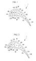
Fig. 1} FIG. 1 is a cross-sectional diagram of a gas turbine blade according to a first embodiment of the present invention. - {
Fig. 2} FIG. 2 is a cross-sectional diagram of a gas turbine blade according to a second embodiment of the present invention. - {
Fig. 3} FIG. 3 is a cross-sectional diagram of a gas turbine blade according to a third embodiment of the present invention. - {
Fig. 4} FIG. 4 is a longitudinal-cross-sectional diagram of a gas turbine blade according to one embodiment of the present invention. - An embodiment according to the present invention will be described below with reference to the drawings.
-
FIG. 4 shows a longitudinal-cross-section of a gas turbine blade according to this embodiment.
The gas turbine blade 1 shown in this figure is one suitably used as a rotor blade. The gas turbine blade 1 is provided with abase portion 6 that forms a platform and a blade portion 4 that is provided so as to stand upright (radial direction) on thebase portion 6, and forms the profile of the blade. - The
base portion 6 is provided with a firstair introduction channel 10A, a secondair introduction channel 10B, and a thirdair introduction channel 10C into which cooling air, which is coolant fluid, is introduced. As the cooling air, part of air compressed by a compressor for compressing combustion air is used. - A plurality of cooling channels extending in the span-wise direction of the blade are formed in the blade portion 4, and a
first cooling channel 12A, asecond cooling channel 12B, athird cooling channel 12C, afourth cooling channel 12D, afifth cooling channel 12E, asixth cooling channel 12F, aseventh cooling channel 12G, and aneighth cooling channel 12H are formed from the leading edge towards the trailing edge of the blade. - The
first cooling channel 12A is connected to the firstair introduction channel 10A. The cooling air introduced from the firstair introduction channel 10A flows from the bottom toward the top (outwards in the radial direction) within thefirst cooling channel 12A, flows to the outside through the film cooling holes (not shown), and cools the outer surface of the blade. - The second to
fourth cooling channels fourth cooling channel 12D is provided at the extreme upstream side, thethird cooling channel 12C is provided at the downstream side thereof, and thesecond cooling channel 12B is provided at the extreme downstream side. Thefourth cooling channel 12D and thethird cooling channel 12C are connected at the distal end of the blade in a folded manner. Furthermore, thethird cooling channel 12C and thesecond cooling channel 12B are connected at the base end of the blade in a folded manner. The secondair introduction channel 10B is connected to thefourth cooling channel 12D, and the cooling air introduced from the secondair introduction channel 10B flows through thefourth cooling channel 12D, thethird cooling channel 12C, and thesecond cooling channel 12B in this order. The cooling air that has flowed to thesecond cooling channel 12B then flows to the outside through film cooling holes (not shown) and cools the outer surface of the blade. - The fifth to
seventh cooling channels fifth cooling channel 12E is provided at the extreme upstream side, thesixth cooling channel 12F is provided downstream thereof, and theseventh cooling channel 12G is provided at the extreme downstream side. Thefifth cooling channel 12E and thesixth cooling channel 12F are connected at the distal end of the blade in a folded manner. Furthermore, thesixth cooling channel 12F and theseventh cooling channel 12G are connected at the base end of the blade in a folded manner. The thirdair introduction channel 10C is connected to thefifth cooling channel 12E, and the cooling air introduced from the thirdair introduction channel 10C flows through thefifth cooling channel 12E, thesixth cooling channel 12F, and theseventh cooling channel 12G in this order. The cooling air that has flowed to theseventh cooling channel 12G flows to the outside through film cooling holes (not shown) and cools the outer surface of the blade. - The cooling air is introduced into the
eighth cooling channel 12H from an air introduction channel, which is not shown. The introduced cooling air flows upwards (outwards in the radial direction) within theeighth cooling channel 12H and flows to the outside from the trailing edge of the blade. -
FIG. 1 shows a lateral cross-section of the gas turbine blade 1. Of the symbols shown in the each of the cooling channels 12 in this figure, a symbol having a solid point inside a circle means that the cooling air flows outwards in the radial direction (from the bottom toward the top inFIG. 4 ) within the channel, and a symbol having an x mark inside a circle means that the cooling air flows inwards in the radial direction (from the top toward the bottom inFIG. 4 ) within the channel. - As shown in this figure, the
first cooling channel 12A and thesecond cooling channel 12B are partitioned by afirst wall portion 22A. Similarly, thesecond cooling channel 12B and thethird cooling channel 12C, thethird cooling channel 12C and thefourth cooling channel 12D, thefourth cooling channel 12D and thefifth cooling channel 12E, thefifth cooling channel 12E and thesixth cooling channel 12F, thesixth cooling channel 12F and theseventh cooling channel 12G, and theseventh cooling channel 12G and theeighth cooling channel 12H are partitioned by asecond wall portion 22B, athird wall portion 22C, afourth wall portion 22D, afifth wall portion 22E, asixth wall portion 22F, and aseventh wall portion 22G, respectively. - The serpentine channel formed by the second to
fourth cooling channels third cooling channel 12C provided downstream of thefourth cooling channel 12D that is provided at the extreme upstream side is made smaller than thisfourth cooling channel 12D, and the channel cross-sectional area of thesecond cooling channel 12B provided downstream of thethird cooling channel 12C is made smaller than thisthird cooling channel 12C. - Furthermore, also with respect to the serpentine channel formed by the fifth to the
seventh cooling channels sixth cooling channel 12F provided downstream of thefifth cooling channel 12E that is provided at the extreme upstream side is made smaller than thisfifth cooling channel 12E, and the channel cross-sectional area of theseventh cooling channel 12G provided downstream of thesixth cooling channel 12F is made smaller than thissixth cooling channel 12F. - By making the channel cross-sectional areas of the cooling channels that constitute the serpentine channel become sequentially smaller from the extreme upstream side to the extreme downstream side in this way, the following effects and advantages are afforded.
Since the cooling air picks up heat by cooling the blade and the temperature thereof is increased as it flows in the serpentine channel, the cooling capacity is reduced. In this embodiment, since the channel cross-sectional area of the serpentine channel is made to become sequentially smaller, the flow rate can be increased as the cooling air flows downstream. Therefore, even though the temperature of the coolant fluid is increased as it flows downstream, the reduction of the heat-conducting capacity can be compensated for by the increased flow rate, and the desired cooling capacity can be achieved. - The
first wall portion 22A and thethird wall portion 22C are arranged such that the distance therebetween becomes greater from the pressureside wall portion 4A towards the suctionside wall portion 4B of the blade. Thesecond wall portion 22B extends substantially parallel to thethird wall portion 22C. Thereby, thesecond channel 12B having a substantially triangular lateral cross-section is formed by thefirst wall portion 22A, thesecond wall portion 22B, and the suctionside wall portion 4B of the blade. Thethird channel 12C having a substantially square lateral cross-section is formed by thesecond wall portion 22B, the suctionside wall portion 4B of the blade, thethird wall portion 22C, and the pressureside wall portion 4A of the blade. - With such a configuration, the following effects and advantages are afforded.
Since thefirst wall portion 22A and thethird wall portion 22C are arranged such that the distance therebetween becomes greater from the pressureside wall portion 4A towards the suctionside wall portion 4B of the blade, the lateral cross-sectional shape formed by thefirst wall portion 22A, thethird wall portion 22C, the pressureside wall portion 4A of the blade, and the suctionside wall portion 4B of the blade becomes substantially a trapezoid in which the pressureside wall portion 4A of the blade is a short side, the suctionside wall portion 4B of the blade is a long side, and thefirst wall portion 22A and thethird wall portion 22C are oblique sides. This trapezoid is divided into a triangle shape and a square shape by thesecond wall portion 22B that extends parallel to thethird wall portion 22C. Accordingly, by using the pressureside wall portion 4A of the blade, which becomes the short side of the trapezoid, as one side of the square, it is possible to achieve a square shape that, as much as possible, does not become flat. Therefore, the heat-conducting surface area of the pressureside wall portion 4A can be made larger, thereby increasing the cooling capacity of the blade. - Furthermore, the
second wall portion 22B is not connected to the pressureside wall portion 4A of the blade but is connected to thefirst wall portion 22A. The effects and advantages afforded thereby are as follows.
If thesecond wall portion 22B were connected to the pressureside wall portion 4A of the blade, and the pressureside wall portion 4A of the blade were covered by the wall thickness of thesecond wall portion 22B, this covered portion would act as an obstruction, and the cooling air would not be able to come into direct contact with the pressureside wall portion 4A of the blade; thus, there is a possibility that the cooling would be insufficient. Therefore, in this embodiment, by connecting thesecond wall portion 22B to thefirst wall portion 22A but not to the pressureside wall portion 4A of the blade, the pressureside wall portion 4A of the blade is prevented from being covered by the wall thickness of thesecond wall portion 22B. Accordingly, a heat-conducting surface area with which the pressureside wall portion 4A of the blade contacts directly with the coolant fluid without being obstructed by thesecond wall portion 22B can be ensured, and the cooling capacity is increased. - In this embodiment, the fourth to
sixth wall portions third wall portion 22C. This is because an advantage is afforded in that a core for forming a cooling channel that is used for casting the gas turbine blade 1 can be drawn in the same direction upon production thereof. - Next, a second embodiment of the present invention will be described with reference to
FIG. 2 . This embodiment differs from the first embodiment in that the extension direction of asecond wall portion 24B is different, and the other structures are the same. Therefore, in the following, only the differences are described, and with respect to the others, similar effects and advantages are afforded. - The
second wall portion 22B extends substantially parallel to thefirst wall portion 22A. Accordingly, asecond channel 12B having a substantially square lateral cross-section is formed by thefirst wall portion 22A, the suctionside wall portion 4B of the blade, thesecond wall portion 22B, and the pressureside wall portion 4A of the blade. Athird channel 12C having a substantially triangular lateral cross-section is formed by thesecond wall portion 22B, the suctionside wall portion 4B of the blade, and thethird wall portion 22C. - With such a configuration, the following effects and advantages are afforded.
Since thefirst wall portion 22A and thethird wall portion 22C are arranged such that the distance therebetween becomes greater from the pressureside wall portion 4A towards the suctionside wall portion 4B of the blade, the lateral cross-sectional shape formed by thefirst wall portion 22A, thethird wall portion 22C, the pressureside wall portion 4A of the blade, and the suctionside wall portion 4B of the blade becomes substantially a trapezoid in which the pressureside wall portion 4A of the blade is the short side, the suctionside wall portion 4B of the blade is the long side, and thefirst wall portion 22A andthird wall portion 22C are the oblique sides. This trapezoid is divided into a square shape and a triangle shape by thesecond wall portion 22B that extends parallel to thefirst wall portion 22A. Accordingly, by using the pressureside wall portion 4A of the blade, which becomes the short side of the trapezoid, as one side of the square, it is possible to achieve a square shape that, as much as possible, does not become flat. Therefore, the heat-conducting surface area of the pressureside wall portion 4A can be made larger, thereby increasing the cooling capacity of the blade. - Furthermore, the
second wall portion 22B is not connected to the pressureside wall portion 4A of the blade but is connected to thethird wall portion 22C. The effects and advantages afforded thereby are as follows.
If thesecond wall portion 22B were connected to the pressureside wall portion 4A of the blade, and the pressureside wall portion 4A of the blade were covered by the wall thickness of thesecond wall portion 22B, this covered portion would act as an obstruction, and the cooling air would not be able to come into direct contact with the pressureside wall portion 4A of the blade; thus, there is a possibility that the cooling would be insufficient. Therefore, in this embodiment, by connecting thesecond wall portion 22B to thethird wall portion 22C but not to the pressureside wall portion 4A of the blade, the pressureside wall portion 4A of the blade is prevented from being covered by the wall thickness of thesecond wall portion 22B. Accordingly, a heat-conducting surface area with which the pressureside wall portion 4A of the blade contacts directly with the coolant fluid without being obstructed by thesecond wall portion 22B can be ensured, and the cooling capacity is increased. - Next, a third embodiment of the present invention will be described with reference to
FIG. 3 . This embodiment differs from the first embodiment and the second embodiment in that the shape of the second wall portion is different, and the other structures are the same. Therefore, in the following, only the differences are described, and with respect to the others, similar effects and advantages are afforded. Note that in this embodiment, unlike the first embodiment and the second embodiment, the second cooling channel or the third cooling channel is not divided into the triangle shape or the square shape by the second wall portion. Therefore, the effects and advantages derived from these configurations are not afforded. - The
second wall portion 25 is in a bent shape. In other words, apressure side portion 25a of thesecond wall portion 25 is formed parallel to thethird wall portion 22C, and asuction side portion 25b of thesecond wall portion 25 is formed parallel to thefirst wall portion 22A. By forming thesecond wall portion 25 in a bent manner in this way, the channel cross-sectional area ratio between thesecond cooling channel 12B and thethird cooling channel 12C constituting the serpentine channel can be adjusted.
Furthermore, in this embodiment, similarly to the first embodiment and the second embodiment, since the channel cross-sectional area of the serpentine channel constituted by the second to thefourth cooling channels seventh cooling channels -
- 1: gas turbine blade
- 4: blade portion
- 6: base portion
- 12A: first cooling channel
- 12B: second cooling channel
- 12C: third cooling channel
- 12D: fourth cooling channel
- 22A: first wall portion
- 22B: second wall portion
- 22C: third wall portion
Claims (6)
- A gas turbine blade comprising a serpentine channel in which a plurality of cooling channels, extending from the base end to the distal end of the blade, are provided from the leading edge to the trailing edge of the blade, at least two of these cooling channels being connected in a folded manner at the base end or the distal end,
wherein the serpentine channel is formed such that the channel cross-sectional area becomes sequentially smaller from the cooling channel at the extreme upstream side of the serpentine channel to the cooling channel at the extreme downstream side. - A gas turbine blade according to Claim 1, further comprising:a first wall portion that partitions a first cooling channel located at the leading edge side and a second cooling channel located adjacent to the trailing edge side of the first cooling channel;a second wall portion that partitions the second cooling channel and a third cooling channel located adjacent to the trailing edge side of the second cooling channel; anda third wall portion that partitions the third cooling channel and a fourth cooling channel located adjacent to the trailing edge side of the third cooling channel;wherein the serpentine channel is formed by the second to fourth cooling channels such that the second cooling channel is provided at the extreme downstream side;
the first wall portion and the third wall portion are arranged such that the distance therebetween becomes greater from the pressure side towards the suction side of the blade;
the second wall portion extends substantially parallel to the third wall portion;
the second channel, having a substantially triangular lateral cross-section, is formed by the first wall portion, the second wall portion, and the suction side wall portion of the blade; and
the third channel, having a substantially square lateral cross-section, is formed by the second wall portion, the suction side wall portion of the blade, the third wall portion, and the pressure side wall portion of the blade. - A gas turbine blade according to Claim 2, wherein the second wall portion is not connected to the pressure side wall portion of the blade but is connected to the first wall portion.
- A gas turbine blade according to Claim 1, further comprising a first wall portion that partitions a first cooling channel located at the leading edge side and a second cooling channel located adjacent to the trailing edge side of the first cooling channel;
a second wall portion that partitions the second cooling channel and a third cooling channel located adjacent to the trailing edge side of the second cooling channel; and
a third wall portion that partitions the third cooling channel and a fourth cooling channel located adjacent to the trailing edge side of the third cooling channel;
wherein the serpentine channel is formed by the second to fourth cooling channels such that the second cooling channel is provided at the extreme downstream side;
the first wall portion and the third wall portion are arranged such that the distance therebetween becomes greater from the pressure side towards the suction side of the blade;
the second wall portion extends substantially parallel to the second wall portion;
the second channel, having a substantially square lateral cross-section, is formed by the first wall portion, the suction side wall portion of the blade, the second wall portion, and the pressure side wall portion of the blade; and
the third channel, having a substantially triangular lateral cross-section, is formed by the second wall portion, the pressure side wall portion of the blade, and the third wall portion. - A gas turbine blade according to Claim 4, wherein the second wall portion is connected to the third wall portion but is not connected to the pressure side wall portion of the blade.
- A gas turbine comprising the gas turbine blade of any one of Claims 1 to 5.
Applications Claiming Priority (2)
| Application Number | Priority Date | Filing Date | Title |
|---|---|---|---|
| JP2008127702A JP5189406B2 (en) | 2008-05-14 | 2008-05-14 | Gas turbine blade and gas turbine provided with the same |
| PCT/JP2009/058824 WO2009139374A1 (en) | 2008-05-14 | 2009-05-12 | Gas turbine blade and gas turbine equipped with the same |
Publications (4)
| Publication Number | Publication Date |
|---|---|
| EP2186999A1 true EP2186999A1 (en) | 2010-05-19 |
| EP2186999A4 EP2186999A4 (en) | 2013-06-19 |
| EP2186999B1 EP2186999B1 (en) | 2014-11-26 |
| EP2186999B8 EP2186999B8 (en) | 2015-01-21 |
Family
ID=41318741
Family Applications (1)
| Application Number | Title | Priority Date | Filing Date |
|---|---|---|---|
| EP09744309.7A Active EP2186999B8 (en) | 2008-05-14 | 2009-05-12 | Gas turbine blade and gas turbine equipped with the same |
Country Status (6)
| Country | Link |
|---|---|
| US (2) | US8465255B2 (en) |
| EP (1) | EP2186999B8 (en) |
| JP (1) | JP5189406B2 (en) |
| KR (1) | KR101163290B1 (en) |
| CN (2) | CN103382857B (en) |
| WO (1) | WO2009139374A1 (en) |
Cited By (2)
| Publication number | Priority date | Publication date | Assignee | Title |
|---|---|---|---|---|
| WO2017039571A1 (en) * | 2015-08-28 | 2017-03-09 | Siemens Aktiengesellschaft | Internally cooled turbine airfoil with flow displacement feature |
| WO2022238051A1 (en) * | 2021-05-11 | 2022-11-17 | Siemens Energy Global GmbH & Co. KG | Rotor-blade tip including cooling configuration |
Families Citing this family (9)
| Publication number | Priority date | Publication date | Assignee | Title |
|---|---|---|---|---|
| JP5189406B2 (en) * | 2008-05-14 | 2013-04-24 | 三菱重工業株式会社 | Gas turbine blade and gas turbine provided with the same |
| US8974182B2 (en) * | 2012-03-01 | 2015-03-10 | General Electric Company | Turbine bucket with a core cavity having a contoured turn |
| WO2015020720A2 (en) * | 2013-06-17 | 2015-02-12 | United Technologies Corporation | Gas turbine engine component with rib support |
| JP6245740B2 (en) * | 2013-11-20 | 2017-12-13 | 三菱日立パワーシステムズ株式会社 | Gas turbine blade |
| KR101790146B1 (en) * | 2015-07-14 | 2017-10-25 | 두산중공업 주식회사 | A gas turbine comprising a cooling system the cooling air supply passage is provided to bypass the outer casing |
| EP3176371A1 (en) * | 2015-12-03 | 2017-06-07 | Siemens Aktiengesellschaft | Component for a fluid flow engine and method |
| EP3433040B1 (en) * | 2016-04-27 | 2023-01-25 | Siemens Energy, Inc. | Gas turbine blade with corrugated tip wall and manufacturing method thereof |
| JP6996947B2 (en) * | 2017-11-09 | 2022-01-17 | 三菱パワー株式会社 | Turbine blades and gas turbines |
| WO2024252886A1 (en) * | 2023-06-05 | 2024-12-12 | 三菱重工業株式会社 | Turbine moving blade and gas turbine |
Family Cites Families (18)
| Publication number | Priority date | Publication date | Assignee | Title |
|---|---|---|---|---|
| US3533711A (en) * | 1966-02-26 | 1970-10-13 | Gen Electric | Cooled vane structure for high temperature turbines |
| US5165852A (en) * | 1990-12-18 | 1992-11-24 | General Electric Company | Rotation enhanced rotor blade cooling using a double row of coolant passageways |
| US5156526A (en) * | 1990-12-18 | 1992-10-20 | General Electric Company | Rotation enhanced rotor blade cooling using a single row of coolant passageways |
| US5660524A (en) * | 1992-07-13 | 1997-08-26 | General Electric Company | Airfoil blade having a serpentine cooling circuit and impingement cooling |
| JP3004478B2 (en) * | 1992-07-22 | 2000-01-31 | 三菱重工業株式会社 | Cross section of cooling air passage for gas turbine air-cooled blade |
| US5348446A (en) * | 1993-04-28 | 1994-09-20 | General Electric Company | Bimetallic turbine airfoil |
| JP3192854B2 (en) * | 1993-12-28 | 2001-07-30 | 株式会社東芝 | Turbine cooling blade |
| JP3040674B2 (en) | 1994-11-16 | 2000-05-15 | 三菱重工業株式会社 | Gas turbine cooling blade |
| US5498133A (en) * | 1995-06-06 | 1996-03-12 | General Electric Company | Pressure regulated film cooling |
| JP3477296B2 (en) | 1995-11-21 | 2003-12-10 | 三菱重工業株式会社 | Gas turbine blades |
| JPH11200893A (en) | 1998-01-12 | 1999-07-27 | Hitachi Ltd | Refrigerant recovery type gas turbine |
| US6126396A (en) | 1998-12-09 | 2000-10-03 | General Electric Company | AFT flowing serpentine airfoil cooling circuit with side wall impingement cooling chambers |
| JP2000230401A (en) | 1999-02-09 | 2000-08-22 | Mitsubishi Heavy Ind Ltd | Gas turbine blade |
| US6206638B1 (en) * | 1999-02-12 | 2001-03-27 | General Electric Company | Low cost airfoil cooling circuit with sidewall impingement cooling chambers |
| US6672836B2 (en) | 2001-12-11 | 2004-01-06 | United Technologies Corporation | Coolable rotor blade for an industrial gas turbine engine |
| US7186085B2 (en) | 2004-11-18 | 2007-03-06 | General Electric Company | Multiform film cooling holes |
| JP2007292006A (en) | 2006-04-27 | 2007-11-08 | Hitachi Ltd | Turbine blade having a cooling passage inside |
| JP5189406B2 (en) * | 2008-05-14 | 2013-04-24 | 三菱重工業株式会社 | Gas turbine blade and gas turbine provided with the same |
-
2008
- 2008-05-14 JP JP2008127702A patent/JP5189406B2/en active Active
-
2009
- 2009-05-12 CN CN201310217182.3A patent/CN103382857B/en active Active
- 2009-05-12 KR KR1020097025541A patent/KR101163290B1/en active Active
- 2009-05-12 WO PCT/JP2009/058824 patent/WO2009139374A1/en not_active Ceased
- 2009-05-12 EP EP09744309.7A patent/EP2186999B8/en active Active
- 2009-05-12 CN CN200980000410.3A patent/CN102016235B/en active Active
- 2009-05-12 US US12/599,833 patent/US8465255B2/en active Active
-
2013
- 2013-06-17 US US13/919,324 patent/US20130280094A1/en not_active Abandoned
Cited By (6)
| Publication number | Priority date | Publication date | Assignee | Title |
|---|---|---|---|---|
| WO2017039571A1 (en) * | 2015-08-28 | 2017-03-09 | Siemens Aktiengesellschaft | Internally cooled turbine airfoil with flow displacement feature |
| CN108026775A (en) * | 2015-08-28 | 2018-05-11 | 西门子公司 | The turbine airfoil of internal cooling with flowing displacement feature part |
| US10494931B2 (en) | 2015-08-28 | 2019-12-03 | Siemens Aktiengesellschaft | Internally cooled turbine airfoil with flow displacement feature |
| CN108026775B (en) * | 2015-08-28 | 2020-03-13 | 西门子公司 | Internally cooled turbine airfoil with flow shifting features |
| WO2022238051A1 (en) * | 2021-05-11 | 2022-11-17 | Siemens Energy Global GmbH & Co. KG | Rotor-blade tip including cooling configuration |
| US12345176B2 (en) | 2021-05-11 | 2025-07-01 | Siemens Energy Global GmbH & Co. KG | Rotor-blade tip including cooling configuration |
Also Published As
| Publication number | Publication date |
|---|---|
| JP5189406B2 (en) | 2013-04-24 |
| US20110044822A1 (en) | 2011-02-24 |
| JP2009275605A (en) | 2009-11-26 |
| EP2186999B8 (en) | 2015-01-21 |
| CN102016235A (en) | 2011-04-13 |
| KR20090131298A (en) | 2009-12-28 |
| CN102016235B (en) | 2014-03-19 |
| US20130280094A1 (en) | 2013-10-24 |
| KR101163290B1 (en) | 2012-07-05 |
| WO2009139374A1 (en) | 2009-11-19 |
| EP2186999A4 (en) | 2013-06-19 |
| EP2186999B1 (en) | 2014-11-26 |
| CN103382857B (en) | 2015-09-09 |
| CN103382857A (en) | 2013-11-06 |
| US8465255B2 (en) | 2013-06-18 |
Similar Documents
| Publication | Publication Date | Title |
|---|---|---|
| US8465255B2 (en) | Gas turbine blade and gas turbine having the same | |
| EP2685048B1 (en) | Gas turbine rotor blade, and gas turbine | |
| EP2592228B1 (en) | Turbine blade and engine component | |
| US8668453B2 (en) | Cooling system having reduced mass pin fins for components in a gas turbine engine | |
| US8221055B1 (en) | Turbine stator vane with endwall cooling | |
| JP4801513B2 (en) | Cooling circuit for moving wing of turbomachine | |
| US20100226789A1 (en) | Turbine blade dual channel cooling system | |
| US20140328669A1 (en) | Airfoil with cooling passages | |
| US20180230815A1 (en) | Turbine airfoil with thin trailing edge cooling circuit | |
| EP2597263B1 (en) | Bucket assembly for turbine system | |
| JP2015127532A (en) | Structural configuration and cooling circuit in turbine blade | |
| JP2008095695A (en) | Movable blade for turbomachine | |
| US7762775B1 (en) | Turbine airfoil with cooled thin trailing edge | |
| CN103089332B (en) | Blade components for turbine systems | |
| US9810071B2 (en) | Internally cooled airfoil | |
| EP2698501B1 (en) | Turbine blade and corresponding gas turbine | |
| US9500093B2 (en) | Internally cooled airfoil | |
| CA2861171A1 (en) | Internally cooled airfoil | |
| EP2597262A1 (en) | Bucket assembly for turbine system | |
| JP5496263B2 (en) | Gas turbine blade and gas turbine provided with the same | |
| JP2015522127A (en) | Air-cooled turbine blades for gas turbines | |
| US20140069108A1 (en) | Bucket assembly for turbomachine | |
| CN107559048A (en) | A kind of rotor blade for middle low heat value heavy duty gas turbine engine |
Legal Events
| Date | Code | Title | Description |
|---|---|---|---|
| PUAI | Public reference made under article 153(3) epc to a published international application that has entered the european phase |
Free format text: ORIGINAL CODE: 0009012 |
|
| 17P | Request for examination filed |
Effective date: 20091116 |
|
| AK | Designated contracting states |
Kind code of ref document: A1 Designated state(s): AT BE BG CH CY CZ DE DK EE ES FI FR GB GR HR HU IE IS IT LI LT LU LV MC MK MT NL NO PL PT RO SE SI SK TR |
|
| AX | Request for extension of the european patent |
Extension state: AL BA RS |
|
| DAX | Request for extension of the european patent (deleted) | ||
| A4 | Supplementary search report drawn up and despatched |
Effective date: 20130517 |
|
| RIC1 | Information provided on ipc code assigned before grant |
Ipc: F01D 5/18 20060101AFI20130513BHEP Ipc: F02C 7/18 20060101ALI20130513BHEP |
|
| GRAP | Despatch of communication of intention to grant a patent |
Free format text: ORIGINAL CODE: EPIDOSNIGR1 |
|
| INTG | Intention to grant announced |
Effective date: 20140630 |
|
| GRAS | Grant fee paid |
Free format text: ORIGINAL CODE: EPIDOSNIGR3 |
|
| GRAA | (expected) grant |
Free format text: ORIGINAL CODE: 0009210 |
|
| AK | Designated contracting states |
Kind code of ref document: B1 Designated state(s): AT BE BG CH CY CZ DE DK EE ES FI FR GB GR HR HU IE IS IT LI LT LU LV MC MK MT NL NO PL PT RO SE SI SK TR |
|
| REG | Reference to a national code |
Ref country code: GB Ref legal event code: FG4D |
|
| REG | Reference to a national code |
Ref country code: CH Ref legal event code: EP |
|
| REG | Reference to a national code |
Ref country code: AT Ref legal event code: REF Ref document number: 698337 Country of ref document: AT Kind code of ref document: T Effective date: 20141215 |
|
| RAP2 | Party data changed (patent owner data changed or rights of a patent transferred) |
Owner name: MITSUBISHI HITACHI POWER SYSTEMS, LTD. |
|
| REG | Reference to a national code |
Ref country code: IE Ref legal event code: FG4D |
|
| REG | Reference to a national code |
Ref country code: DE Ref legal event code: R096 Ref document number: 602009027966 Country of ref document: DE Effective date: 20150108 |
|
| REG | Reference to a national code |
Ref country code: NL Ref legal event code: VDEP Effective date: 20141126 |
|
| RAP2 | Party data changed (patent owner data changed or rights of a patent transferred) |
Owner name: MITSUBISHI HITACHI POWER SYSTEMS, LTD. |
|
| REG | Reference to a national code |
Ref country code: AT Ref legal event code: MK05 Ref document number: 698337 Country of ref document: AT Kind code of ref document: T Effective date: 20141126 |
|
| REG | Reference to a national code |
Ref country code: LT Ref legal event code: MG4D |
|
| PG25 | Lapsed in a contracting state [announced via postgrant information from national office to epo] |
Ref country code: NO Free format text: LAPSE BECAUSE OF FAILURE TO SUBMIT A TRANSLATION OF THE DESCRIPTION OR TO PAY THE FEE WITHIN THE PRESCRIBED TIME-LIMIT Effective date: 20150226 Ref country code: ES Free format text: LAPSE BECAUSE OF FAILURE TO SUBMIT A TRANSLATION OF THE DESCRIPTION OR TO PAY THE FEE WITHIN THE PRESCRIBED TIME-LIMIT Effective date: 20141126 Ref country code: NL Free format text: LAPSE BECAUSE OF FAILURE TO SUBMIT A TRANSLATION OF THE DESCRIPTION OR TO PAY THE FEE WITHIN THE PRESCRIBED TIME-LIMIT Effective date: 20141126 Ref country code: LT Free format text: LAPSE BECAUSE OF FAILURE TO SUBMIT A TRANSLATION OF THE DESCRIPTION OR TO PAY THE FEE WITHIN THE PRESCRIBED TIME-LIMIT Effective date: 20141126 Ref country code: FI Free format text: LAPSE BECAUSE OF FAILURE TO SUBMIT A TRANSLATION OF THE DESCRIPTION OR TO PAY THE FEE WITHIN THE PRESCRIBED TIME-LIMIT Effective date: 20141126 Ref country code: PT Free format text: LAPSE BECAUSE OF FAILURE TO SUBMIT A TRANSLATION OF THE DESCRIPTION OR TO PAY THE FEE WITHIN THE PRESCRIBED TIME-LIMIT Effective date: 20150326 Ref country code: IS Free format text: LAPSE BECAUSE OF FAILURE TO SUBMIT A TRANSLATION OF THE DESCRIPTION OR TO PAY THE FEE WITHIN THE PRESCRIBED TIME-LIMIT Effective date: 20150326 |
|
| PG25 | Lapsed in a contracting state [announced via postgrant information from national office to epo] |
Ref country code: LV Free format text: LAPSE BECAUSE OF FAILURE TO SUBMIT A TRANSLATION OF THE DESCRIPTION OR TO PAY THE FEE WITHIN THE PRESCRIBED TIME-LIMIT Effective date: 20141126 Ref country code: HR Free format text: LAPSE BECAUSE OF FAILURE TO SUBMIT A TRANSLATION OF THE DESCRIPTION OR TO PAY THE FEE WITHIN THE PRESCRIBED TIME-LIMIT Effective date: 20141126 Ref country code: CY Free format text: LAPSE BECAUSE OF FAILURE TO SUBMIT A TRANSLATION OF THE DESCRIPTION OR TO PAY THE FEE WITHIN THE PRESCRIBED TIME-LIMIT Effective date: 20141126 Ref country code: GR Free format text: LAPSE BECAUSE OF FAILURE TO SUBMIT A TRANSLATION OF THE DESCRIPTION OR TO PAY THE FEE WITHIN THE PRESCRIBED TIME-LIMIT Effective date: 20150227 Ref country code: AT Free format text: LAPSE BECAUSE OF FAILURE TO SUBMIT A TRANSLATION OF THE DESCRIPTION OR TO PAY THE FEE WITHIN THE PRESCRIBED TIME-LIMIT Effective date: 20141126 Ref country code: SE Free format text: LAPSE BECAUSE OF FAILURE TO SUBMIT A TRANSLATION OF THE DESCRIPTION OR TO PAY THE FEE WITHIN THE PRESCRIBED TIME-LIMIT Effective date: 20141126 |
|
| PG25 | Lapsed in a contracting state [announced via postgrant information from national office to epo] |
Ref country code: RO Free format text: LAPSE BECAUSE OF FAILURE TO SUBMIT A TRANSLATION OF THE DESCRIPTION OR TO PAY THE FEE WITHIN THE PRESCRIBED TIME-LIMIT Effective date: 20141126 Ref country code: CZ Free format text: LAPSE BECAUSE OF FAILURE TO SUBMIT A TRANSLATION OF THE DESCRIPTION OR TO PAY THE FEE WITHIN THE PRESCRIBED TIME-LIMIT Effective date: 20141126 Ref country code: EE Free format text: LAPSE BECAUSE OF FAILURE TO SUBMIT A TRANSLATION OF THE DESCRIPTION OR TO PAY THE FEE WITHIN THE PRESCRIBED TIME-LIMIT Effective date: 20141126 Ref country code: SK Free format text: LAPSE BECAUSE OF FAILURE TO SUBMIT A TRANSLATION OF THE DESCRIPTION OR TO PAY THE FEE WITHIN THE PRESCRIBED TIME-LIMIT Effective date: 20141126 Ref country code: DK Free format text: LAPSE BECAUSE OF FAILURE TO SUBMIT A TRANSLATION OF THE DESCRIPTION OR TO PAY THE FEE WITHIN THE PRESCRIBED TIME-LIMIT Effective date: 20141126 |
|
| REG | Reference to a national code |
Ref country code: DE Ref legal event code: R097 Ref document number: 602009027966 Country of ref document: DE |
|
| PG25 | Lapsed in a contracting state [announced via postgrant information from national office to epo] |
Ref country code: PL Free format text: LAPSE BECAUSE OF FAILURE TO SUBMIT A TRANSLATION OF THE DESCRIPTION OR TO PAY THE FEE WITHIN THE PRESCRIBED TIME-LIMIT Effective date: 20141126 |
|
| PLBE | No opposition filed within time limit |
Free format text: ORIGINAL CODE: 0009261 |
|
| STAA | Information on the status of an ep patent application or granted ep patent |
Free format text: STATUS: NO OPPOSITION FILED WITHIN TIME LIMIT |
|
| 26N | No opposition filed |
Effective date: 20150827 |
|
| REG | Reference to a national code |
Ref country code: CH Ref legal event code: PL |
|
| PG25 | Lapsed in a contracting state [announced via postgrant information from national office to epo] |
Ref country code: MC Free format text: LAPSE BECAUSE OF FAILURE TO SUBMIT A TRANSLATION OF THE DESCRIPTION OR TO PAY THE FEE WITHIN THE PRESCRIBED TIME-LIMIT Effective date: 20141126 Ref country code: LU Free format text: LAPSE BECAUSE OF FAILURE TO SUBMIT A TRANSLATION OF THE DESCRIPTION OR TO PAY THE FEE WITHIN THE PRESCRIBED TIME-LIMIT Effective date: 20150512 Ref country code: CH Free format text: LAPSE BECAUSE OF NON-PAYMENT OF DUE FEES Effective date: 20150531 Ref country code: LI Free format text: LAPSE BECAUSE OF NON-PAYMENT OF DUE FEES Effective date: 20150531 |
|
| REG | Reference to a national code |
Ref country code: IE Ref legal event code: MM4A |
|
| REG | Reference to a national code |
Ref country code: FR Ref legal event code: ST Effective date: 20160129 |
|
| PG25 | Lapsed in a contracting state [announced via postgrant information from national office to epo] |
Ref country code: SI Free format text: LAPSE BECAUSE OF FAILURE TO SUBMIT A TRANSLATION OF THE DESCRIPTION OR TO PAY THE FEE WITHIN THE PRESCRIBED TIME-LIMIT Effective date: 20141126 |
|
| PG25 | Lapsed in a contracting state [announced via postgrant information from national office to epo] |
Ref country code: IE Free format text: LAPSE BECAUSE OF NON-PAYMENT OF DUE FEES Effective date: 20150512 |
|
| PG25 | Lapsed in a contracting state [announced via postgrant information from national office to epo] |
Ref country code: FR Free format text: LAPSE BECAUSE OF NON-PAYMENT OF DUE FEES Effective date: 20150601 |
|
| PG25 | Lapsed in a contracting state [announced via postgrant information from national office to epo] |
Ref country code: MT Free format text: LAPSE BECAUSE OF FAILURE TO SUBMIT A TRANSLATION OF THE DESCRIPTION OR TO PAY THE FEE WITHIN THE PRESCRIBED TIME-LIMIT Effective date: 20141126 |
|
| PG25 | Lapsed in a contracting state [announced via postgrant information from national office to epo] |
Ref country code: HU Free format text: LAPSE BECAUSE OF FAILURE TO SUBMIT A TRANSLATION OF THE DESCRIPTION OR TO PAY THE FEE WITHIN THE PRESCRIBED TIME-LIMIT; INVALID AB INITIO Effective date: 20090512 Ref country code: BG Free format text: LAPSE BECAUSE OF FAILURE TO SUBMIT A TRANSLATION OF THE DESCRIPTION OR TO PAY THE FEE WITHIN THE PRESCRIBED TIME-LIMIT Effective date: 20141126 |
|
| PG25 | Lapsed in a contracting state [announced via postgrant information from national office to epo] |
Ref country code: TR Free format text: LAPSE BECAUSE OF FAILURE TO SUBMIT A TRANSLATION OF THE DESCRIPTION OR TO PAY THE FEE WITHIN THE PRESCRIBED TIME-LIMIT Effective date: 20141126 |
|
| PG25 | Lapsed in a contracting state [announced via postgrant information from national office to epo] |
Ref country code: BE Free format text: LAPSE BECAUSE OF FAILURE TO SUBMIT A TRANSLATION OF THE DESCRIPTION OR TO PAY THE FEE WITHIN THE PRESCRIBED TIME-LIMIT Effective date: 20141126 |
|
| PG25 | Lapsed in a contracting state [announced via postgrant information from national office to epo] |
Ref country code: MK Free format text: LAPSE BECAUSE OF FAILURE TO SUBMIT A TRANSLATION OF THE DESCRIPTION OR TO PAY THE FEE WITHIN THE PRESCRIBED TIME-LIMIT Effective date: 20141126 |
|
| REG | Reference to a national code |
Ref country code: DE Ref legal event code: R082 Ref document number: 602009027966 Country of ref document: DE Representative=s name: HENKEL & PARTNER MBB PATENTANWALTSKANZLEI, REC, DE Ref country code: DE Ref legal event code: R081 Ref document number: 602009027966 Country of ref document: DE Owner name: MITSUBISHI POWER, LTD., JP Free format text: FORMER OWNER: MITSUBISHI HITACHI POWER SYSTEMS, LTD., YOKOHAMA-SHI, KANAGAWA, JP |
|
| PGFP | Annual fee paid to national office [announced via postgrant information from national office to epo] |
Ref country code: GB Payment date: 20260323 Year of fee payment: 18 |
|
| PGFP | Annual fee paid to national office [announced via postgrant information from national office to epo] |
Ref country code: IT Payment date: 20260422 Year of fee payment: 18 |
|
| PGFP | Annual fee paid to national office [announced via postgrant information from national office to epo] |
Ref country code: DE Payment date: 20260402 Year of fee payment: 18 |