EP2186461A2 - Dust collector - Google Patents
Dust collector Download PDFInfo
- Publication number
- EP2186461A2 EP2186461A2 EP09013717A EP09013717A EP2186461A2 EP 2186461 A2 EP2186461 A2 EP 2186461A2 EP 09013717 A EP09013717 A EP 09013717A EP 09013717 A EP09013717 A EP 09013717A EP 2186461 A2 EP2186461 A2 EP 2186461A2
- Authority
- EP
- European Patent Office
- Prior art keywords
- hook
- housing
- dust collector
- main body
- pull
- Prior art date
- Legal status (The legal status is an assumption and is not a legal conclusion. Google has not performed a legal analysis and makes no representation as to the accuracy of the status listed.)
- Granted
Links
Images



Classifications
-
- A—HUMAN NECESSITIES
- A47—FURNITURE; DOMESTIC ARTICLES OR APPLIANCES; COFFEE MILLS; SPICE MILLS; SUCTION CLEANERS IN GENERAL
- A47L—DOMESTIC WASHING OR CLEANING; SUCTION CLEANERS IN GENERAL
- A47L9/00—Details or accessories of suction cleaners, e.g. mechanical means for controlling the suction or for effecting pulsating action; Storing devices specially adapted to suction cleaners or parts thereof; Carrying-vehicles specially adapted for suction cleaners
- A47L9/28—Installation of the electric equipment, e.g. adaptation or attachment to the suction cleaner; Controlling suction cleaners by electric means
- A47L9/2857—User input or output elements for control, e.g. buttons, switches or displays
-
- A—HUMAN NECESSITIES
- A47—FURNITURE; DOMESTIC ARTICLES OR APPLIANCES; COFFEE MILLS; SPICE MILLS; SUCTION CLEANERS IN GENERAL
- A47L—DOMESTIC WASHING OR CLEANING; SUCTION CLEANERS IN GENERAL
- A47L5/00—Structural features of suction cleaners
- A47L5/12—Structural features of suction cleaners with power-driven air-pumps or air-compressors, e.g. driven by motor vehicle engine vacuum
- A47L5/22—Structural features of suction cleaners with power-driven air-pumps or air-compressors, e.g. driven by motor vehicle engine vacuum with rotary fans
- A47L5/36—Suction cleaners with hose between nozzle and casing; Suction cleaners for fixing on staircases; Suction cleaners for carrying on the back
- A47L5/365—Suction cleaners with hose between nozzle and casing; Suction cleaners for fixing on staircases; Suction cleaners for carrying on the back of the vertical type, e.g. tank or bucket type
-
- A—HUMAN NECESSITIES
- A47—FURNITURE; DOMESTIC ARTICLES OR APPLIANCES; COFFEE MILLS; SPICE MILLS; SUCTION CLEANERS IN GENERAL
- A47L—DOMESTIC WASHING OR CLEANING; SUCTION CLEANERS IN GENERAL
- A47L9/00—Details or accessories of suction cleaners, e.g. mechanical means for controlling the suction or for effecting pulsating action; Storing devices specially adapted to suction cleaners or parts thereof; Carrying-vehicles specially adapted for suction cleaners
-
- A—HUMAN NECESSITIES
- A47—FURNITURE; DOMESTIC ARTICLES OR APPLIANCES; COFFEE MILLS; SPICE MILLS; SUCTION CLEANERS IN GENERAL
- A47L—DOMESTIC WASHING OR CLEANING; SUCTION CLEANERS IN GENERAL
- A47L9/00—Details or accessories of suction cleaners, e.g. mechanical means for controlling the suction or for effecting pulsating action; Storing devices specially adapted to suction cleaners or parts thereof; Carrying-vehicles specially adapted for suction cleaners
- A47L9/0009—Storing devices ; Supports, stands or holders
-
- A—HUMAN NECESSITIES
- A47—FURNITURE; DOMESTIC ARTICLES OR APPLIANCES; COFFEE MILLS; SPICE MILLS; SUCTION CLEANERS IN GENERAL
- A47L—DOMESTIC WASHING OR CLEANING; SUCTION CLEANERS IN GENERAL
- A47L9/00—Details or accessories of suction cleaners, e.g. mechanical means for controlling the suction or for effecting pulsating action; Storing devices specially adapted to suction cleaners or parts thereof; Carrying-vehicles specially adapted for suction cleaners
- A47L9/0009—Storing devices ; Supports, stands or holders
- A47L9/0018—Storing devices ; Supports, stands or holders integrated in or removably mounted upon the suction cleaner for storing parts of said suction cleaner
- A47L9/0036—Storing devices ; Supports, stands or holders integrated in or removably mounted upon the suction cleaner for storing parts of said suction cleaner specially adapted for holding the suction hose
-
- A—HUMAN NECESSITIES
- A47—FURNITURE; DOMESTIC ARTICLES OR APPLIANCES; COFFEE MILLS; SPICE MILLS; SUCTION CLEANERS IN GENERAL
- A47L—DOMESTIC WASHING OR CLEANING; SUCTION CLEANERS IN GENERAL
- A47L9/00—Details or accessories of suction cleaners, e.g. mechanical means for controlling the suction or for effecting pulsating action; Storing devices specially adapted to suction cleaners or parts thereof; Carrying-vehicles specially adapted for suction cleaners
- A47L9/22—Mountings for motor fan assemblies
-
- A—HUMAN NECESSITIES
- A47—FURNITURE; DOMESTIC ARTICLES OR APPLIANCES; COFFEE MILLS; SPICE MILLS; SUCTION CLEANERS IN GENERAL
- A47L—DOMESTIC WASHING OR CLEANING; SUCTION CLEANERS IN GENERAL
- A47L9/00—Details or accessories of suction cleaners, e.g. mechanical means for controlling the suction or for effecting pulsating action; Storing devices specially adapted to suction cleaners or parts thereof; Carrying-vehicles specially adapted for suction cleaners
- A47L9/28—Installation of the electric equipment, e.g. adaptation or attachment to the suction cleaner; Controlling suction cleaners by electric means
- A47L9/2836—Installation of the electric equipment, e.g. adaptation or attachment to the suction cleaner; Controlling suction cleaners by electric means characterised by the parts which are controlled
- A47L9/2842—Suction motors or blowers
-
- A—HUMAN NECESSITIES
- A47—FURNITURE; DOMESTIC ARTICLES OR APPLIANCES; COFFEE MILLS; SPICE MILLS; SUCTION CLEANERS IN GENERAL
- A47L—DOMESTIC WASHING OR CLEANING; SUCTION CLEANERS IN GENERAL
- A47L9/00—Details or accessories of suction cleaners, e.g. mechanical means for controlling the suction or for effecting pulsating action; Storing devices specially adapted to suction cleaners or parts thereof; Carrying-vehicles specially adapted for suction cleaners
- A47L9/32—Handles
- A47L9/327—Handles for suction cleaners with hose between nozzle and casing
Definitions
- This invention relates to a dust collector which can be used in combination with a power tool.
- a dust collector known in the art comprises a main body having an air intake unit formed with a motor-driven intake fan, and a tank having an opening formed at an upper side thereof which is sealed off from outside with the main body provided over the tank.
- the tank has an inlet to which a hose or the like may be attached, through which outside air is sucked into the tank by the action of rotating the intake fan.
- the outside air thus sucked into the tank is filtered by a filter provided between the main body and the opening of the tank, so that dust or the like can be caught and stored in the tank.
- this type of dust collector may be used in combination of a power tool, such as a circular saw; that is, with a hose having one end attached to the inlet of the tank and the other end connected to the power tool, the dust collector is driven while the power tool is being operated, so that chips or the like produced by the power tool can be directly collected.
- a power tool such as a circular saw
- the dust collector When the dust collector is used in combination with the power tool as described above, the dust collector may also be utilized to temporarily place the power tool thereon when the operation of the power tool is suspended.
- the power tool is typically placed on an upper side of the main body of the dust collector.
- the upper side of the main body is usually provided with a carrying handle for enhanced portability, as in the dust collector illustrated in JP 3-60256 B , and thus has depressions and projections thereon.
- the power tool may have depressions and projections; for example a circular saw typically has a safety cover protruding down from a base. Accordingly, the power tool would not be stably placed on the main body of the dust collector, and could possibly drop from the dust collector.
- the present invention has been made in an attempt to eliminate the above disadvantages, and illustrative, non-limiting embodiments of the present invention may overcome the above disadvantages and other disadvantages not described above.
- a hook is provided in a housing of a main body of a dust collector.
- the hook is capable of being manually operated to change a position thereof to one of a retracted position and a pull-out position.
- the hook in the retracted position is completely embedded in a profile of the housing, and the hook in the pull-out position projects sideward from the housing with a hooked end portion thereof oriented upward.
- a plurality of ribs which extend parallel to one another in an upward and downward direction when the hook is in the pull-out position may optionally be provided on an inner surface of the hooked end portion facing toward the housing.
- an additional feature for more effectively preventing the power tool temporarily placed on the dust collector from dropping may optionally be provided.
- the hooked end portion of the hook may have a length such that the hooked end portion is higher than an upper surface of the housing when the hook is in the pull-out position.
- an additional feature for facilitating the operation of the hook may optionally be provided.
- the housing may be shaped like a box with a flat upper surface
- the hook may comprise a plate member bent into a shape like a letter L, wherein the plate member has a lower end joined to the main body at a lower portion of a side wall of the housing in a manner that permits the plate member to tilt downward and upward.
- the hook is capable of being operated to rotate between the retracted position and the pull-out position.
- a power tool can be temporarily placed on an upper surface of the main body of the dust collector in a stable state. Therefore, the usability can be increased. Moreover, since the hook can be used to hold accessories such as a hose or a cord, etc., it is also convenient for storing such accessories.
- the hook is reinforced by the ribs, so that the durability of the hook can be increased, and prevention of slipping or dropping of the hose or other accessories held at the inner surface of the hooked end portion of the hook may be expected.
- a dust collector 1 principally includes a tank 2, and a main body 3 disposed over the tank 2.
- the tank 2 has an opening formed at an upper side thereof, and an inlet (not shown) formed in a side wall thereof protrusively from the side wall outward.
- the main body 3 comprises a cowling 4 as one example of a housing, and an air intake unit 5 housed in the cowling 4.
- the main body 3 further comprises a tank cover 6 which is configured to seal off the opening of the tank 2 and to support the air intake unit 5 of the main body 3.
- the air intake unit 5 is disposed in the center of the opening of the tank 2, supported and suspended by the tank cover 6.
- the air intake unit 5 includes a motor 7, and intake fans 8 which can be driven by the motor 7 to rotate.
- the tank cover 6 has intake holes 9 provided just beneath the intake fans 8 at the bottom of the air intake unit 5.
- Denoted by reference numeral 10 is an air passage formed inside the main body 3 and communicating with the air intake unit 5.
- Denoted by reference numeral 11 is a cloth filter shaped like a bag and configured to be held between the tank cover 6 and the opening of the tank 2 and to intercept dust or the like which would otherwise flow from the inlet to the air intake unit 5 while causing air to path therethrough.
- Denoted by reference numeral 12 are casters provided at the bottom of the tank 2.
- the cowling 4 is shaped like a box with a flat upper surface; at a side surface thereof, as shown in FIG. 3 , a rotary switch 13 for an operation selector with a dial, an interlock power socket 14 with a cap, and other components are provided. To the interlock power socket 14, a power cord of a power tool may be connected.
- a U-shaped handle 15 is provided with both end thereof rotatably joined to the cowling 4. The handle 15 is configured to be rotatable between a retracted position (as indicated by solid lines in FIG. 1 ) and a pull-out position (as indicated by dashed lines in FIG. 1 ).
- the handle 15 in the retracted position is fitted in a recess 16 formed in the cowling 4 without projecting from the cowling 4; on this account, the recess 16 is contoured to fit the profile of the handle 15.
- the handle 15 in the pull-out position stands at the center of the upper surface of the cowling 4.
- the main body 3 further comprises a hook 17 provided on a different side of the cowling 4 from the side of which the recess 16 is formed.
- the hook 17 is a plate member bent into a shape like a letter L, having a lower plate 18 and an upper plate 19.
- the lower plate 18 has an outer surface curved to conform with the shape of the side surface of the cowling 4.
- the upper plate 19 extends contiguously from an upper edge of the lower plate 18 in a direction perpendicular to the lower plate so as to form a hooked end portion, and has a flat outer surface which conforms with the shape of the upper surface of the cowling 4.
- On the inner surfaces of the lower plate 18 and the upper plate 19, a plurality of ribs 20 are provided being parallel to one another along the inner surfaces of the both plates 18 and 19 at predetermined intervals.
- a trimmed portion 21 is provided which has a shape corresponding to that of the hook 17.
- pins 22 are provided on two opposed outer sides of a lower end portion of the lower plate 18.
- holding holes 23 for the pins 22 are provided on two opposed inside walls of the trimmed portion 21 (at the lower portion of the side wall of the housing). Accordingly, with the pins 22 fitted in the holding holes 23, respectively, the hook 17 is rendered rotatable between a retracted position (as indicated by solid lines in FIG. 1 ; see also FIG. 3 ) and a pull-out position (as indicated by dashed lines in FIG. 1 ; see also FIG. 4 ).
- the retracted position is the position in which the hook 17 is tilted toward the cowling 4 and completely stored in the trimmed portion
- the pull-out position is the position in which the hook 17 projects sideward from the cowling 4 with the upper plate 19 oriented upward.
- upper end faces of the upper plate 19 and the ribs 20 are positioned parallel to the upper surface of the cowling 4, and kept slightly higher than that of the upper surface of the cowling 4.
- Denoted by reference numeral 24 is a finger notch which is a recessed portion formed at the center of the inner edge of the upper plate 19 and configured to allow a finger to be inserted therein so that the operation of rotating the hook 17 from the retracted position to the pull-out position can be performed with increased ease.
- mounting screws 25 are provided, respectively, to mount the cowling 4 to the air intake unit 5 and the tank cover 6 by which the intake unit 5 is supported.
- These mounting screws 25 are arranged in such positions that they are hidden under the handle 15 and the hook 17 in their retracted positions while the mounting screws 25 are accessibly uncovered when the handle 15 and the hook 17 are in their pull-out positions. Therefore, when the cowling 4 needs to be removed for a repair of the air intake unit 5, the mounting screws 25 can easily be uncovered and unfastened; thus, the handle 15 and the hook 17 would not impair its easy serviceability.
- the dust collector 1 configured as described above, in operation, when the rotary switch 13 is turned ON and the motor 7 starts driving the intake fans 8 to rotate, outside air is sucked through a hose or the like attached to the inlet of the tank 2 into the tank 2, and passes through the filter 11; thereafter, the air having passed through the filter 11 is forwarded through the intake holes 9 to the air passage 10 inside the cowling 4, and then discharged through an air outlet (not shown) provided in the cowling 4 to the outside. During this suction process, any dust or dirt in the sucked air is caught in the filter 11, and stored in the tank 2.
- the hose attached to the inlet of the tank 2 is connected to a power tool such as a circular saw, chips produced during the use of the power tool can be directly collected through the hose without being scattered.
- the hook 17 may be stored in the retracted position when the dust collector 1 is in operation, so that the hook 17 is completely embedded in the trimmed portion 21 without projecting from the cowling 4 as described above, thus would never obstruct the operation.
- the hook 17 may be pulled out into the pull-out position so that the circular saw 30 can be placed on the dust collector 1 with a base 31 put on the upper surface of the cowling 4 and on the end face of the upper plate 19.
- a safety cover 32 covering a saw blade which protrudes down below the base 31 fits in a space between the upper plate 19 of the hook 17 and the cowling 4. In this way, the circular saw 30 can be temporarily placed on the upper side of the main body 3.
- the base 31 is tilted with its upper plate 19 side lifted up to some extent, and thus the potential risk of that the circular saw 30 drops from the outside edge of the main body 3 is reduced.
- the circular saw 30 may be placed with the safety cover 32 put close to the cowling 4 and the majority portion of the base 31 may be laid on the upper surface of the cowling 4, as shown in FIG. 6 .
- the hook 17 may serve any purpose other than that of temporarily placing a circular saw or other power tool thereon; for example, as shown in FIG. 7 , an end portion of the hose 33, or other accessories such as a nozzle may be held between the upper plate 19 of the hook 17 and the cowling 4. In this way, the end portion of the hose 33 wound around the periphery of the dust collector 1 with its end opposite to the end portion being retained attached to the inlet of the dust collector 1 can be held by the hook 17, so that the hose 33 can be prevented from being untied and spread out.
- the ribs 20 of the upper plate 19 engage with the bellows of the hose 33 so as to prevent a slip of the hose 33; thus, the hose 33 is held with high degree of reliability.
- accessorial components which can be held by the hook 17 are not limited to the hose; for example, the power cord(s) for the dust collector 1 and/or the power tool may be looped and tied up so as to be held in the hook 17.
- the hook 17 capable of being manually operated to change a position thereof to one of the retracted position in which the hook 17 is completely embedded in the profile of the cowling 4 and the pull-out position in which the hook 17 projects sideward from the cowling 4 with the upper plate 19 oriented upward is provided in the cowling 4 of the main body 3. Therefore, the power tool can be temporarily placed on the upper side of the main body 3 in a stable state, and thus the usability can be improved. Moreover, the hook 17 can be used to hold a hose or a cord, etc. Furthermore, the hook 17 in the retracted position provides a storage space inside, such that accessories can be stored therein, which is highly convenient and useful.
- the ribs 20 which extend parallel to one another in an upward and downward direction when the hook 17 is in the pull-out position are provided on the inner surface of upper plate 19 facing toward the cowling 4. Therefore, the hook 17 is reinforced by the ribs 20, so that the durability of the hook 17 is increased, and prevention of slipping or dropping of the hose 33 or other accessories may be expected.
- the upper plate 19 of the hook 17 is configured to have a length such that the upper plate 19 is higher than the upper surface of the cowling 4 when the hook 17 is in the pull-out position.
- the circular saw 30 can be supported in a position with its outer side tilting upward to some extent, and thus the potential risk of that the circular saw 30 temporarily placed thereon slips off and drops down outside from the main body 3 can be reduced.
- the cowling 4 is shaped like a box with a flat upper surface
- the hook 17 comprises a plate member bent into a shape like a letter L, wherein the plate member has a lower end joined to the main body 3 at a lower portion of the side wall of the cowling 4 in a manner that permits the plate member to tilt downward and upward.
- the hook 17 is capable of being operated to rotate between the retracted position and the pull-out position. Therefore, the operation for moving (rotating) the hook 17 between the retracted position and the pull-out position can be performed with increased ease.
- the hook may be designed differently from the specific configuration illustrated above; for example, the ribs may be omitted while the thickness of the hook may be increased, instead; and the pins may be provided at the cowling side and fitted in the holding holes provided in the hook.
- the hook is shaped like a letter L composed of the lower and the upper plates in the above-described embodiment, a pair of L-shaped bars may be provided of which midpoints are connected by a bar to form the shape of a letter H.
- the configuration of the hook is not limited to the above-described embodiment, but may be modified according to the shape of the housing or the like.
- a single hook is provided in the above-described embodiment, a plurality of hooks may be provided.
Landscapes
- Engineering & Computer Science (AREA)
- Mechanical Engineering (AREA)
- Electric Suction Cleaners (AREA)
- Cleaning Implements For Floors, Carpets, Furniture, Walls, And The Like (AREA)
- Filtering Of Dispersed Particles In Gases (AREA)
- Grinding-Machine Dressing And Accessory Apparatuses (AREA)
- Percussive Tools And Related Accessories (AREA)
- Cyclones (AREA)
Abstract
Description
- This invention relates to a dust collector which can be used in combination with a power tool.
- A dust collector known in the art (for example, see
JP 3-60256 B - When the dust collector is used in combination with the power tool as described above, the dust collector may also be utilized to temporarily place the power tool thereon when the operation of the power tool is suspended. On this occasion, the power tool is typically placed on an upper side of the main body of the dust collector. However, the upper side of the main body is usually provided with a carrying handle for enhanced portability, as in the dust collector illustrated in
JP 3-60256 B - Thus, there is a need to provide a dust collector of which a main body has an upper side on which a power tool can be temporarily placed in a stable state and thus provide an improved usability.
- The present invention has been made in an attempt to eliminate the above disadvantages, and illustrative, non-limiting embodiments of the present invention may overcome the above disadvantages and other disadvantages not described above.
- In a first aspect of the present invention, a hook is provided in a housing of a main body of a dust collector. The hook is capable of being manually operated to change a position thereof to one of a retracted position and a pull-out position. The hook in the retracted position is completely embedded in a profile of the housing, and the hook in the pull-out position projects sideward from the housing with a hooked end portion thereof oriented upward.
- In a second aspect according to the configuration described above in the first aspect, a plurality of ribs which extend parallel to one another in an upward and downward direction when the hook is in the pull-out position may optionally be provided on an inner surface of the hooked end portion facing toward the housing.
- In a third aspect according to the configurations described above in the first and the second aspects, an additional feature for more effectively preventing the power tool temporarily placed on the dust collector from dropping may optionally be provided. More specifically, in the third aspect, for example, the hooked end portion of the hook may have a length such that the hooked end portion is higher than an upper surface of the housing when the hook is in the pull-out position.
- In a fourth aspect according to the configurations described above in any one of the first to the third aspect, an additional feature for facilitating the operation of the hook may optionally be provided. More specifically, in the fourth aspect, for example, the housing may be shaped like a box with a flat upper surface, and the hook may comprise a plate member bent into a shape like a letter L, wherein the plate member has a lower end joined to the main body at a lower portion of a side wall of the housing in a manner that permits the plate member to tilt downward and upward. The hook is capable of being operated to rotate between the retracted position and the pull-out position.
- The following advantageous effects may be expected by implementing the present invention in such a way as described above.
- According to the configuration as described in the first aspect, a power tool can be temporarily placed on an upper surface of the main body of the dust collector in a stable state. Therefore, the usability can be increased. Moreover, since the hook can be used to hold accessories such as a hose or a cord, etc., it is also convenient for storing such accessories.
- According to the additional feature as described in the second aspect, further advantage may be obtained in addition to that of the first aspect; that is, the hook is reinforced by the ribs, so that the durability of the hook can be increased, and prevention of slipping or dropping of the hose or other accessories held at the inner surface of the hooked end portion of the hook may be expected.
- According to the additional feature as described in the third aspect, further advantage may be obtained in addition to that of the first or the second aspect; that is, setting the height (length) of the hooked end portion of the hook appropriately as defined in the third aspect makes it possible to support a power tool in a position with its outer side tilting upward to some extent, such that the potential risk of that the power tool temporarily placed thereon slips off and drops down outside from the main body of the dust collector can be reduced.
- According to the additional feature as described in the fourth aspect, further advantage may be obtained in addition to that of any one of the first to the third aspect; that is, the operation for moving (rotating) the hook between the retracted position and the pull-out position can be performed with increased ease.
- The above aspect, other advantages and further features of the present invention will become more apparent by describing in detail illustrative, non-limiting embodiments thereof with reference to the accompanying drawings, in which:
-
FIG. 1 is a vertical sectional view of a dust collector according to an exemplary embodiment of the present invention; -
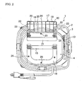
FIG. 2 is a plan view of the dust collector shown inFIG. 1 ; -
FIG. 3 is a perspective view of a main body of the dust collector with a hook in a retracted position; -
FIG. 4 is a perspective view of the main body of the dust collector with the hook in a pull-out position; -
FIG. 5 is an elevation view of the main body of the dust collector illustrated with a circular saw placed temporarily thereon; -
FIG. 6 is an elevation view of the main body of the dust collector illustrated with a circular saw placed temporarily thereon in a position different from that shown inFIG. 5 ; and -
FIG. 7 is a perspective view of the main body of the dust collector illustrated with a hose held in the hook. - Exemplary embodiments of the present invention will be described hereinafter with reference to the accompanying drawings.
- Referring now to
FIGS. 1 and2 , adust collector 1 principally includes atank 2, and amain body 3 disposed over thetank 2. Thetank 2 has an opening formed at an upper side thereof, and an inlet (not shown) formed in a side wall thereof protrusively from the side wall outward. Themain body 3 comprises a cowling 4 as one example of a housing, and anair intake unit 5 housed in the cowling 4. Themain body 3 further comprises atank cover 6 which is configured to seal off the opening of thetank 2 and to support theair intake unit 5 of themain body 3. Theair intake unit 5 is disposed in the center of the opening of thetank 2, supported and suspended by thetank cover 6. Theair intake unit 5 includes amotor 7, andintake fans 8 which can be driven by themotor 7 to rotate. Thetank cover 6 hasintake holes 9 provided just beneath theintake fans 8 at the bottom of theair intake unit 5. Denoted byreference numeral 10 is an air passage formed inside themain body 3 and communicating with theair intake unit 5. Denoted byreference numeral 11 is a cloth filter shaped like a bag and configured to be held between thetank cover 6 and the opening of thetank 2 and to intercept dust or the like which would otherwise flow from the inlet to theair intake unit 5 while causing air to path therethrough. Denoted byreference numeral 12 are casters provided at the bottom of thetank 2. - The
cowling 4 is shaped like a box with a flat upper surface; at a side surface thereof, as shown inFIG. 3 , arotary switch 13 for an operation selector with a dial, aninterlock power socket 14 with a cap, and other components are provided. To theinterlock power socket 14, a power cord of a power tool may be connected. At the center of an upper surface of thecowling 4, aU-shaped handle 15 is provided with both end thereof rotatably joined to the cowling 4. Thehandle 15 is configured to be rotatable between a retracted position (as indicated by solid lines inFIG. 1 ) and a pull-out position (as indicated by dashed lines inFIG. 1 ). Thehandle 15 in the retracted position is fitted in arecess 16 formed in thecowling 4 without projecting from thecowling 4; on this account, therecess 16 is contoured to fit the profile of thehandle 15. Thehandle 15 in the pull-out position stands at the center of the upper surface of the cowling 4. - The
main body 3 further comprises ahook 17 provided on a different side of thecowling 4 from the side of which therecess 16 is formed. Thehook 17 is a plate member bent into a shape like a letter L, having alower plate 18 and anupper plate 19. Thelower plate 18 has an outer surface curved to conform with the shape of the side surface of thecowling 4. Theupper plate 19 extends contiguously from an upper edge of thelower plate 18 in a direction perpendicular to the lower plate so as to form a hooked end portion, and has a flat outer surface which conforms with the shape of the upper surface of thecowling 4. On the inner surfaces of thelower plate 18 and theupper plate 19, a plurality ofribs 20 are provided being parallel to one another along the inner surfaces of the bothplates - At an outer surface of the
cowling 4, a trimmedportion 21 is provided which has a shape corresponding to that of thehook 17. On two opposed outer sides of a lower end portion of thelower plate 18,pins 22 are provided. On two opposed inside walls of the trimmed portion 21 (at the lower portion of the side wall of the housing), holdingholes 23 for thepins 22 are provided. Accordingly, with thepins 22 fitted in the holding holes 23, respectively, thehook 17 is rendered rotatable between a retracted position (as indicated by solid lines inFIG. 1 ; see alsoFIG. 3 ) and a pull-out position (as indicated by dashed lines inFIG. 1 ; see alsoFIG. 4 ). Here, the retracted position is the position in which thehook 17 is tilted toward thecowling 4 and completely stored in the trimmed portion, while the pull-out position is the position in which thehook 17 projects sideward from thecowling 4 with theupper plate 19 oriented upward. In this pull-out position, upper end faces of theupper plate 19 and theribs 20 are positioned parallel to the upper surface of thecowling 4, and kept slightly higher than that of the upper surface of thecowling 4. - Denoted by
reference numeral 24 is a finger notch which is a recessed portion formed at the center of the inner edge of theupper plate 19 and configured to allow a finger to be inserted therein so that the operation of rotating thehook 17 from the retracted position to the pull-out position can be performed with increased ease. - At the bottom of the
recess 16 for receiving thehandle 15 and at the bottom of the trimmedportion 21 for receiving thehook 17, mountingscrews 25 are provided, respectively, to mount thecowling 4 to theair intake unit 5 and thetank cover 6 by which theintake unit 5 is supported. These mountingscrews 25 are arranged in such positions that they are hidden under thehandle 15 and thehook 17 in their retracted positions while the mountingscrews 25 are accessibly uncovered when thehandle 15 and thehook 17 are in their pull-out positions. Therefore, when thecowling 4 needs to be removed for a repair of theair intake unit 5, the mountingscrews 25 can easily be uncovered and unfastened; thus, thehandle 15 and thehook 17 would not impair its easy serviceability. - With the
dust collector 1 configured as described above, in operation, when therotary switch 13 is turned ON and themotor 7 starts driving theintake fans 8 to rotate, outside air is sucked through a hose or the like attached to the inlet of thetank 2 into thetank 2, and passes through thefilter 11; thereafter, the air having passed through thefilter 11 is forwarded through the intake holes 9 to theair passage 10 inside thecowling 4, and then discharged through an air outlet (not shown) provided in thecowling 4 to the outside. During this suction process, any dust or dirt in the sucked air is caught in thefilter 11, and stored in thetank 2. Therefore, when the hose attached to the inlet of thetank 2 is connected to a power tool such as a circular saw, chips produced during the use of the power tool can be directly collected through the hose without being scattered. Thehook 17 may be stored in the retracted position when thedust collector 1 is in operation, so that thehook 17 is completely embedded in the trimmedportion 21 without projecting from thecowling 4 as described above, thus would never obstruct the operation. - In cases for example where a
circular saw 30 is connected to thedust collector 1 and put into operation, when an operator suspends the operation and wishes to temporarily put thecircular saw 30 down, thehook 17 may be pulled out into the pull-out position so that thecircular saw 30 can be placed on thedust collector 1 with a base 31 put on the upper surface of thecowling 4 and on the end face of theupper plate 19. At that time, asafety cover 32 covering a saw blade which protrudes down below the base 31 fits in a space between theupper plate 19 of thehook 17 and thecowling 4. In this way, thecircular saw 30 can be temporarily placed on the upper side of themain body 3. In particular, since theupper plate 19 protrudes upward beyond the upper surface of thecowling 4, thebase 31 is tilted with itsupper plate 19 side lifted up to some extent, and thus the potential risk of that thecircular saw 30 drops from the outside edge of themain body 3 is reduced. However, depending upon the type of thecircular saw 30, thecircular saw 30 may be placed with thesafety cover 32 put close to thecowling 4 and the majority portion of the base 31 may be laid on the upper surface of thecowling 4, as shown inFIG. 6 . - On the other hand, the
hook 17 may serve any purpose other than that of temporarily placing a circular saw or other power tool thereon; for example, as shown inFIG. 7 , an end portion of thehose 33, or other accessories such as a nozzle may be held between theupper plate 19 of thehook 17 and thecowling 4. In this way, the end portion of thehose 33 wound around the periphery of thedust collector 1 with its end opposite to the end portion being retained attached to the inlet of thedust collector 1 can be held by thehook 17, so that thehose 33 can be prevented from being untied and spread out. In particular, when thehose 33 is held by thehook 17, theribs 20 of theupper plate 19 engage with the bellows of thehose 33 so as to prevent a slip of thehose 33; thus, thehose 33 is held with high degree of reliability. It is to be understood that accessorial components which can be held by thehook 17 are not limited to the hose; for example, the power cord(s) for thedust collector 1 and/or the power tool may be looped and tied up so as to be held in thehook 17. - As described above, in the
dust collector 1 according to the present embodiment, thehook 17 capable of being manually operated to change a position thereof to one of the retracted position in which thehook 17 is completely embedded in the profile of thecowling 4 and the pull-out position in which thehook 17 projects sideward from thecowling 4 with theupper plate 19 oriented upward is provided in thecowling 4 of themain body 3. Therefore, the power tool can be temporarily placed on the upper side of themain body 3 in a stable state, and thus the usability can be improved. Moreover, thehook 17 can be used to hold a hose or a cord, etc. Furthermore, thehook 17 in the retracted position provides a storage space inside, such that accessories can be stored therein, which is highly convenient and useful. - In this embodiment, particularly, the
ribs 20 which extend parallel to one another in an upward and downward direction when thehook 17 is in the pull-out position are provided on the inner surface ofupper plate 19 facing toward thecowling 4. Therefore, thehook 17 is reinforced by theribs 20, so that the durability of thehook 17 is increased, and prevention of slipping or dropping of thehose 33 or other accessories may be expected. - Moreover, in this embodiment, the
upper plate 19 of thehook 17 is configured to have a length such that theupper plate 19 is higher than the upper surface of thecowling 4 when thehook 17 is in the pull-out position. In this configuration, thecircular saw 30 can be supported in a position with its outer side tilting upward to some extent, and thus the potential risk of that thecircular saw 30 temporarily placed thereon slips off and drops down outside from themain body 3 can be reduced. - Further in this embodiment, the
cowling 4 is shaped like a box with a flat upper surface, and thehook 17 comprises a plate member bent into a shape like a letter L, wherein the plate member has a lower end joined to themain body 3 at a lower portion of the side wall of thecowling 4 in a manner that permits the plate member to tilt downward and upward. Thehook 17 is capable of being operated to rotate between the retracted position and the pull-out position. Therefore, the operation for moving (rotating) thehook 17 between the retracted position and the pull-out position can be performed with increased ease. - The hook may be designed differently from the specific configuration illustrated above; for example, the ribs may be omitted while the thickness of the hook may be increased, instead; and the pins may be provided at the cowling side and fitted in the holding holes provided in the hook. Although the hook is shaped like a letter L composed of the lower and the upper plates in the above-described embodiment, a pair of L-shaped bars may be provided of which midpoints are connected by a bar to form the shape of a letter H. As long as a power tool can be stably supported by the hook in the pull-out position, the configuration of the hook is not limited to the above-described embodiment, but may be modified according to the shape of the housing or the like. Although a single hook is provided in the above-described embodiment, a plurality of hooks may be provided.
- It is explicitly stated that all features disclosed in the description and/or the claims are intended to be disclosed separately and independently from each other for the purpose of original disclosure as well as for the purpose of restricting the claimed invention independent of the composition of the features in the embodiments and/or the claims. It is explicitly stated that all value ranges or indications of groups of entities disclose every possible intermediate value or intermediate entity for the purpose of original disclosure as well as for the purpose of restricting the claimed invention, in particular as limits of value ranges.
Claims (11)
- A dust collector comprising a main body (3) in which an air intake unit (5) is incorporated and a tank (2) over which the main body (3) is disposed, wherein
a hook (17) capable of being manually operated to change a position thereof to one of a retracted position and a pull-out position is provided in a housing (4) of the main body (3), the hook (17) in the retracted position is completely embedded in a profile of the housing (4), while the hook (17) in the pull-out position projects sideward from the housing (4) with a hooked end portion (19) thereof oriented upward. - The dust collector according to claim 1, wherein the hook (17) comprises a plurality of ribs (20) provided on an inner surface of the hooked end portion (19) facing toward the housing (4), the plurality of ribs (20) extending parallel to one another in an upward and downward direction when the hook (17) is in the pull-out position.
- The dust collector according to claim 1 or 2, wherein the hooked end portion (19) of the hook (17) has a length such that the hooked end portion (19) is higher than an upper surface of the housing (4) when the hook (17) is in the pull-out position.
- The dust collector according to any one of claims 1 to 3, wherein the housing (4) is shaped like a box with a flat upper surface, and the hook (17) comprises a plate member bent into a shape like a letter L, and the plate member has a lower end joined to the main body (3) at a lower portion of a side wall of the housing (4) in a manner that permits the plate member to tilt downward and upward whereby the hook (17) is capable of being operated to rotate between the retracted position and the pull-out position.
- The dust collector according to claim 4, wherein the hook (17) further comprises a pin (22) provided at the lower end of the plate member, and the main body (3) further comprises a holding hole (23) provided at the lower portion of the side walls of the housing (4), the pin (22) being disposed inside the holding hole (23) whereby the hook (17) is joined to the main body (3).
- The dust collector according to any one of claims 1 to 5, wherein the hook (17) comprises a recessed portion (24) provided at an edge of the hooked end portion (19) and configured to allow a finger to be inserted therein.
- The dust collector according to any one of claims 1 to 6, wherein the main body (3) further comprises a trimmed portion (21) provided at an outer surface of the housing (4), the trimmed portion (21) being configured to have a shape corresponding to that of the hook (17) such that the hook (17) in the retracted position is completely stored in the trimmed portion (21).
- The dust collector according to claim 7, wherein the main body (3) further comprises a mounting screw (25) provided at a bottom surface of the trimmed portion (21) to mount the housing (4) to the air intake unit (5).
- The dust collector according to any one of claims 1 to 8, wherein the main body (3) further comprises a handle (15) provided at a center of an upper surface of the housing (4) in a position where the handle (15) does not interfere with the hook (17), the handle (15) being configured to be rotatable between a retracted position and a pull-out position, the handle (15) in the retracted position is fitted in a recess (16) formed in the housing (4) without projecting from the housing (4), and the handle (15) in the pull-out position stands at the center of the upper surface of the housing (4).
- The dust collector according to claim 9, wherein the handle (15) is in a U-shaped and both end thereof are rotatably joined to the housing (4).
- The dust collector according to claim 9 or 10, wherein the main body (3) further comprises a mounting screw (25) provided at a bottom surface of the recess (16) to mount the housing (4) to the air intake unit (5).
Applications Claiming Priority (1)
| Application Number | Priority Date | Filing Date | Title |
|---|---|---|---|
| JP2008294678A JP5430910B2 (en) | 2008-11-18 | 2008-11-18 | Dust collector |
Publications (3)
| Publication Number | Publication Date |
|---|---|
| EP2186461A2 true EP2186461A2 (en) | 2010-05-19 |
| EP2186461A3 EP2186461A3 (en) | 2010-07-21 |
| EP2186461B1 EP2186461B1 (en) | 2012-04-25 |
Family
ID=41606614
Family Applications (1)
| Application Number | Title | Priority Date | Filing Date |
|---|---|---|---|
| EP09013717A Active EP2186461B1 (en) | 2008-11-18 | 2009-10-30 | Dust collector |
Country Status (6)
| Country | Link |
|---|---|
| US (1) | US7913352B2 (en) |
| EP (1) | EP2186461B1 (en) |
| JP (1) | JP5430910B2 (en) |
| CN (1) | CN101733266B (en) |
| AT (1) | ATE554689T1 (en) |
| RU (1) | RU2519928C2 (en) |
Cited By (1)
| Publication number | Priority date | Publication date | Assignee | Title |
|---|---|---|---|---|
| WO2012062580A1 (en) * | 2010-11-08 | 2012-05-18 | Alfred Kärcher Gmbh & Co. Kg | Holder for a hose and suction device having a holder of this kind |
Families Citing this family (13)
| Publication number | Priority date | Publication date | Assignee | Title |
|---|---|---|---|---|
| US9776296B2 (en) | 2008-05-09 | 2017-10-03 | Milwaukee Electric Tool Corporation | Power tool dust collector |
| US8967923B2 (en) | 2012-01-13 | 2015-03-03 | Aeg Electric Tools Gmbh | Dust suction device for drilling machine |
| JP5808660B2 (en) * | 2011-12-13 | 2015-11-10 | 株式会社マキタ | Dust collector |
| CN104207726B (en) * | 2013-06-04 | 2017-03-01 | 天佑电器(苏州)有限公司 | A kind of vacuum cleaner with hose clip |
| JP6422217B2 (en) * | 2014-02-13 | 2018-11-14 | 株式会社マキタ | Dust collector |
| JP2015150148A (en) * | 2014-02-13 | 2015-08-24 | 株式会社マキタ | dust collector |
| US9980618B2 (en) * | 2014-02-13 | 2018-05-29 | Makita Corporation | Dust collecting device |
| JP6837731B2 (en) * | 2014-04-28 | 2021-03-03 | 工機ホールディングス株式会社 | Dust collector |
| DE102014013633A1 (en) * | 2014-09-19 | 2016-03-24 | Nilfisk-Advance A/S | adapter plate |
| KR102643822B1 (en) * | 2015-08-31 | 2024-03-07 | 제이피엘 글로벌, 엘엘씨 | Circular saw apparatus with integrated multistage filtration system |
| US10239136B2 (en) | 2015-08-31 | 2019-03-26 | JPL Global, LLC | Circular saw apparatus with integrated multistage filtration system |
| CN109008797B (en) * | 2017-06-09 | 2024-07-02 | 天佑电器(苏州)有限公司 | Dust collector |
| CN111491710B (en) * | 2017-12-14 | 2021-12-24 | 工机控股株式会社 | Dust collector |
Citations (1)
| Publication number | Priority date | Publication date | Assignee | Title |
|---|---|---|---|---|
| JPH0360256B2 (en) | 1985-10-11 | 1991-09-13 | Hitachi Ltd |
Family Cites Families (15)
| Publication number | Priority date | Publication date | Assignee | Title |
|---|---|---|---|---|
| US2355034A (en) * | 1941-10-17 | 1944-08-01 | Thomas K Scott | Toolholder for vacuum cleaners |
| US2573091A (en) * | 1946-03-29 | 1951-10-30 | Jr Charles Kepler Brown | Combined vacuum cleaner and tool casing |
| US2918692A (en) * | 1957-07-16 | 1959-12-29 | Health Mor Inc | Suction cleaner tool holder construction |
| JPS4834624Y1 (en) * | 1969-02-14 | 1973-10-19 | ||
| JPS5626046U (en) * | 1979-08-08 | 1981-03-10 | ||
| JPS60119369U (en) * | 1984-01-20 | 1985-08-12 | 株式会社日立製作所 | handle assembly |
| DE3440910A1 (en) * | 1984-11-09 | 1986-05-15 | Licentia Patent-Verwaltungs-Gmbh, 6000 Frankfurt | Vacuum cleaner with a hinged lid for accessories |
| JPH0315424A (en) * | 1989-10-28 | 1991-01-23 | Hitachi Ltd | vacuum cleaner |
| US5031266A (en) * | 1989-12-21 | 1991-07-16 | Whirlpool Corporation | Vacuum cleaner wand seal |
| JP3060256B2 (en) | 1991-08-29 | 2000-07-10 | 片岡物産株式会社 | Coffee pack |
| JPH05261034A (en) * | 1992-03-18 | 1993-10-12 | Hitachi Ltd | Cleaner |
| JP3648738B2 (en) * | 2002-01-11 | 2005-05-18 | ツインバード工業株式会社 | Handheld vacuum cleaner |
| JP2004073687A (en) * | 2002-08-21 | 2004-03-11 | Hitachi Koki Co Ltd | Dust collector |
| JP2005218477A (en) * | 2004-02-03 | 2005-08-18 | Matsushita Electric Ind Co Ltd | Electric vacuum cleaner |
| US7662200B2 (en) * | 2005-10-18 | 2010-02-16 | Electrolux Home Care Products, Inc. | Vacuum bag mounting and viewing features |
-
2008
- 2008-11-18 JP JP2008294678A patent/JP5430910B2/en active Active
-
2009
- 2009-10-30 EP EP09013717A patent/EP2186461B1/en active Active
- 2009-10-30 AT AT09013717T patent/ATE554689T1/en active
- 2009-10-30 CN CN2009102077740A patent/CN101733266B/en active Active
- 2009-11-02 US US12/588,913 patent/US7913352B2/en active Active
- 2009-11-17 RU RU2009142370/12A patent/RU2519928C2/en active
Patent Citations (1)
| Publication number | Priority date | Publication date | Assignee | Title |
|---|---|---|---|---|
| JPH0360256B2 (en) | 1985-10-11 | 1991-09-13 | Hitachi Ltd |
Cited By (1)
| Publication number | Priority date | Publication date | Assignee | Title |
|---|---|---|---|---|
| WO2012062580A1 (en) * | 2010-11-08 | 2012-05-18 | Alfred Kärcher Gmbh & Co. Kg | Holder for a hose and suction device having a holder of this kind |
Also Published As
| Publication number | Publication date |
|---|---|
| EP2186461B1 (en) | 2012-04-25 |
| RU2519928C2 (en) | 2014-06-20 |
| RU2009142370A (en) | 2011-05-27 |
| CN101733266A (en) | 2010-06-16 |
| CN101733266B (en) | 2012-10-24 |
| EP2186461A3 (en) | 2010-07-21 |
| JP2010119505A (en) | 2010-06-03 |
| US7913352B2 (en) | 2011-03-29 |
| US20100122427A1 (en) | 2010-05-20 |
| JP5430910B2 (en) | 2014-03-05 |
| ATE554689T1 (en) | 2012-05-15 |
Similar Documents
| Publication | Publication Date | Title |
|---|---|---|
| US7913352B2 (en) | Dust collector | |
| CN104949214B (en) | Dehumidifier | |
| US20180220861A1 (en) | Vacuum cleaner | |
| US20110219582A1 (en) | Integrated bag door and carry handle for a floor cleaner | |
| US10575691B2 (en) | Upright vacuum cleaner including rotary brush | |
| JP6653533B2 (en) | Vacuum cleaner | |
| KR20170029138A (en) | Humidifier and control method thereof | |
| JP2017217190A (en) | Vacuum cleaner | |
| JP2010104390A (en) | Dry and wet vacuum cleaner | |
| US20070227617A1 (en) | Adjustable vacuum food storage container | |
| JP2019188238A (en) | Cleaner | |
| CN209678385U (en) | vacuum cleaner | |
| JP5808660B2 (en) | Dust collector | |
| JP6750911B2 (en) | Vacuum cleaner | |
| JP4347021B2 (en) | Dust case mounting structure for cutting tools | |
| CN208941989U (en) | Cleaning equipment and mite removal device | |
| JP2006198152A (en) | Electric vacuum cleaner | |
| JPH05141705A (en) | Dehumidifier | |
| JP6393428B2 (en) | Adapter plate | |
| CN100548203C (en) | Vacuum cleaner with housing for accessories | |
| JPH06269384A (en) | Vacuum cleaner | |
| JP6815661B2 (en) | Vacuum cleaner head and vacuum cleaner | |
| CN108392133A (en) | Dust catcher | |
| JP3209519U (en) | Dust collector sander device | |
| CN121196387A (en) | Vacuum cleaners and accessories |
Legal Events
| Date | Code | Title | Description |
|---|---|---|---|
| PUAI | Public reference made under article 153(3) epc to a published international application that has entered the european phase |
Free format text: ORIGINAL CODE: 0009012 |
|
| AK | Designated contracting states |
Kind code of ref document: A2 Designated state(s): AT BE BG CH CY CZ DE DK EE ES FI FR GB GR HR HU IE IS IT LI LT LU LV MC MK MT NL NO PL PT RO SE SI SK SM TR |
|
| AX | Request for extension of the european patent |
Extension state: AL BA RS |
|
| PUAL | Search report despatched |
Free format text: ORIGINAL CODE: 0009013 |
|
| AK | Designated contracting states |
Kind code of ref document: A3 Designated state(s): AT BE BG CH CY CZ DE DK EE ES FI FR GB GR HR HU IE IS IT LI LT LU LV MC MK MT NL NO PL PT RO SE SI SK SM TR |
|
| AX | Request for extension of the european patent |
Extension state: AL BA RS |
|
| RIC1 | Information provided on ipc code assigned before grant |
Ipc: A47L 9/00 20060101ALI20100615BHEP Ipc: A47L 9/22 20060101ALI20100615BHEP Ipc: A47L 9/32 20060101ALI20100615BHEP Ipc: A47L 5/36 20060101ALI20100615BHEP Ipc: A47L 9/28 20060101ALI20100615BHEP Ipc: A47L 7/00 20060101AFI20100215BHEP |
|
| 17P | Request for examination filed |
Effective date: 20101207 |
|
| GRAP | Despatch of communication of intention to grant a patent |
Free format text: ORIGINAL CODE: EPIDOSNIGR1 |
|
| GRAS | Grant fee paid |
Free format text: ORIGINAL CODE: EPIDOSNIGR3 |
|
| GRAA | (expected) grant |
Free format text: ORIGINAL CODE: 0009210 |
|
| AK | Designated contracting states |
Kind code of ref document: B1 Designated state(s): AT BE BG CH CY CZ DE DK EE ES FI FR GB GR HR HU IE IS IT LI LT LU LV MC MK MT NL NO PL PT RO SE SI SK SM TR |
|
| REG | Reference to a national code |
Ref country code: GB Ref legal event code: FG4D |
|
| REG | Reference to a national code |
Ref country code: CH Ref legal event code: EP |
|
| REG | Reference to a national code |
Ref country code: AT Ref legal event code: REF Ref document number: 554689 Country of ref document: AT Kind code of ref document: T Effective date: 20120515 |
|
| REG | Reference to a national code |
Ref country code: IE Ref legal event code: FG4D |
|
| REG | Reference to a national code |
Ref country code: DE Ref legal event code: R096 Ref document number: 602009006480 Country of ref document: DE Effective date: 20120614 |
|
| REG | Reference to a national code |
Ref country code: NL Ref legal event code: VDEP Effective date: 20120425 |
|
| REG | Reference to a national code |
Ref country code: AT Ref legal event code: MK05 Ref document number: 554689 Country of ref document: AT Kind code of ref document: T Effective date: 20120425 |
|
| LTIE | Lt: invalidation of european patent or patent extension |
Effective date: 20120425 |
|
| PG25 | Lapsed in a contracting state [announced via postgrant information from national office to epo] |
Ref country code: PL Free format text: LAPSE BECAUSE OF FAILURE TO SUBMIT A TRANSLATION OF THE DESCRIPTION OR TO PAY THE FEE WITHIN THE PRESCRIBED TIME-LIMIT Effective date: 20120425 Ref country code: NO Free format text: LAPSE BECAUSE OF FAILURE TO SUBMIT A TRANSLATION OF THE DESCRIPTION OR TO PAY THE FEE WITHIN THE PRESCRIBED TIME-LIMIT Effective date: 20120725 Ref country code: IS Free format text: LAPSE BECAUSE OF FAILURE TO SUBMIT A TRANSLATION OF THE DESCRIPTION OR TO PAY THE FEE WITHIN THE PRESCRIBED TIME-LIMIT Effective date: 20120825 Ref country code: FI Free format text: LAPSE BECAUSE OF FAILURE TO SUBMIT A TRANSLATION OF THE DESCRIPTION OR TO PAY THE FEE WITHIN THE PRESCRIBED TIME-LIMIT Effective date: 20120425 Ref country code: SE Free format text: LAPSE BECAUSE OF FAILURE TO SUBMIT A TRANSLATION OF THE DESCRIPTION OR TO PAY THE FEE WITHIN THE PRESCRIBED TIME-LIMIT Effective date: 20120425 Ref country code: LT Free format text: LAPSE BECAUSE OF FAILURE TO SUBMIT A TRANSLATION OF THE DESCRIPTION OR TO PAY THE FEE WITHIN THE PRESCRIBED TIME-LIMIT Effective date: 20120425 Ref country code: CY Free format text: LAPSE BECAUSE OF FAILURE TO SUBMIT A TRANSLATION OF THE DESCRIPTION OR TO PAY THE FEE WITHIN THE PRESCRIBED TIME-LIMIT Effective date: 20120425 |
|
| PG25 | Lapsed in a contracting state [announced via postgrant information from national office to epo] |
Ref country code: HR Free format text: LAPSE BECAUSE OF FAILURE TO SUBMIT A TRANSLATION OF THE DESCRIPTION OR TO PAY THE FEE WITHIN THE PRESCRIBED TIME-LIMIT Effective date: 20120425 Ref country code: LV Free format text: LAPSE BECAUSE OF FAILURE TO SUBMIT A TRANSLATION OF THE DESCRIPTION OR TO PAY THE FEE WITHIN THE PRESCRIBED TIME-LIMIT Effective date: 20120425 Ref country code: PT Free format text: LAPSE BECAUSE OF FAILURE TO SUBMIT A TRANSLATION OF THE DESCRIPTION OR TO PAY THE FEE WITHIN THE PRESCRIBED TIME-LIMIT Effective date: 20120827 Ref country code: SI Free format text: LAPSE BECAUSE OF FAILURE TO SUBMIT A TRANSLATION OF THE DESCRIPTION OR TO PAY THE FEE WITHIN THE PRESCRIBED TIME-LIMIT Effective date: 20120425 Ref country code: GR Free format text: LAPSE BECAUSE OF FAILURE TO SUBMIT A TRANSLATION OF THE DESCRIPTION OR TO PAY THE FEE WITHIN THE PRESCRIBED TIME-LIMIT Effective date: 20120726 |
|
| PG25 | Lapsed in a contracting state [announced via postgrant information from national office to epo] |
Ref country code: BE Free format text: LAPSE BECAUSE OF FAILURE TO SUBMIT A TRANSLATION OF THE DESCRIPTION OR TO PAY THE FEE WITHIN THE PRESCRIBED TIME-LIMIT Effective date: 20120425 |
|
| PG25 | Lapsed in a contracting state [announced via postgrant information from national office to epo] |
Ref country code: NL Free format text: LAPSE BECAUSE OF FAILURE TO SUBMIT A TRANSLATION OF THE DESCRIPTION OR TO PAY THE FEE WITHIN THE PRESCRIBED TIME-LIMIT Effective date: 20120425 Ref country code: CZ Free format text: LAPSE BECAUSE OF FAILURE TO SUBMIT A TRANSLATION OF THE DESCRIPTION OR TO PAY THE FEE WITHIN THE PRESCRIBED TIME-LIMIT Effective date: 20120425 Ref country code: DK Free format text: LAPSE BECAUSE OF FAILURE TO SUBMIT A TRANSLATION OF THE DESCRIPTION OR TO PAY THE FEE WITHIN THE PRESCRIBED TIME-LIMIT Effective date: 20120425 Ref country code: SK Free format text: LAPSE BECAUSE OF FAILURE TO SUBMIT A TRANSLATION OF THE DESCRIPTION OR TO PAY THE FEE WITHIN THE PRESCRIBED TIME-LIMIT Effective date: 20120425 Ref country code: EE Free format text: LAPSE BECAUSE OF FAILURE TO SUBMIT A TRANSLATION OF THE DESCRIPTION OR TO PAY THE FEE WITHIN THE PRESCRIBED TIME-LIMIT Effective date: 20120425 Ref country code: AT Free format text: LAPSE BECAUSE OF FAILURE TO SUBMIT A TRANSLATION OF THE DESCRIPTION OR TO PAY THE FEE WITHIN THE PRESCRIBED TIME-LIMIT Effective date: 20120425 Ref country code: RO Free format text: LAPSE BECAUSE OF FAILURE TO SUBMIT A TRANSLATION OF THE DESCRIPTION OR TO PAY THE FEE WITHIN THE PRESCRIBED TIME-LIMIT Effective date: 20120425 |
|
| PG25 | Lapsed in a contracting state [announced via postgrant information from national office to epo] |
Ref country code: IT Free format text: LAPSE BECAUSE OF FAILURE TO SUBMIT A TRANSLATION OF THE DESCRIPTION OR TO PAY THE FEE WITHIN THE PRESCRIBED TIME-LIMIT Effective date: 20120425 |
|
| PLBE | No opposition filed within time limit |
Free format text: ORIGINAL CODE: 0009261 |
|
| STAA | Information on the status of an ep patent application or granted ep patent |
Free format text: STATUS: NO OPPOSITION FILED WITHIN TIME LIMIT |
|
| 26N | No opposition filed |
Effective date: 20130128 |
|
| PG25 | Lapsed in a contracting state [announced via postgrant information from national office to epo] |
Ref country code: ES Free format text: LAPSE BECAUSE OF FAILURE TO SUBMIT A TRANSLATION OF THE DESCRIPTION OR TO PAY THE FEE WITHIN THE PRESCRIBED TIME-LIMIT Effective date: 20120805 |
|
| REG | Reference to a national code |
Ref country code: DE Ref legal event code: R097 Ref document number: 602009006480 Country of ref document: DE Effective date: 20130128 |
|
| PG25 | Lapsed in a contracting state [announced via postgrant information from national office to epo] |
Ref country code: MC Free format text: LAPSE BECAUSE OF NON-PAYMENT OF DUE FEES Effective date: 20121031 |
|
| PG25 | Lapsed in a contracting state [announced via postgrant information from national office to epo] |
Ref country code: BG Free format text: LAPSE BECAUSE OF FAILURE TO SUBMIT A TRANSLATION OF THE DESCRIPTION OR TO PAY THE FEE WITHIN THE PRESCRIBED TIME-LIMIT Effective date: 20120725 |
|
| REG | Reference to a national code |
Ref country code: IE Ref legal event code: MM4A |
|
| PG25 | Lapsed in a contracting state [announced via postgrant information from national office to epo] |
Ref country code: IE Free format text: LAPSE BECAUSE OF NON-PAYMENT OF DUE FEES Effective date: 20121030 |
|
| PG25 | Lapsed in a contracting state [announced via postgrant information from national office to epo] |
Ref country code: MT Free format text: LAPSE BECAUSE OF FAILURE TO SUBMIT A TRANSLATION OF THE DESCRIPTION OR TO PAY THE FEE WITHIN THE PRESCRIBED TIME-LIMIT Effective date: 20120425 |
|
| PG25 | Lapsed in a contracting state [announced via postgrant information from national office to epo] |
Ref country code: TR Free format text: LAPSE BECAUSE OF FAILURE TO SUBMIT A TRANSLATION OF THE DESCRIPTION OR TO PAY THE FEE WITHIN THE PRESCRIBED TIME-LIMIT Effective date: 20120425 |
|
| PG25 | Lapsed in a contracting state [announced via postgrant information from national office to epo] |
Ref country code: SM Free format text: LAPSE BECAUSE OF FAILURE TO SUBMIT A TRANSLATION OF THE DESCRIPTION OR TO PAY THE FEE WITHIN THE PRESCRIBED TIME-LIMIT Effective date: 20120425 Ref country code: LU Free format text: LAPSE BECAUSE OF NON-PAYMENT OF DUE FEES Effective date: 20121030 |
|
| REG | Reference to a national code |
Ref country code: CH Ref legal event code: PL |
|
| PG25 | Lapsed in a contracting state [announced via postgrant information from national office to epo] |
Ref country code: LI Free format text: LAPSE BECAUSE OF NON-PAYMENT OF DUE FEES Effective date: 20131031 Ref country code: CH Free format text: LAPSE BECAUSE OF NON-PAYMENT OF DUE FEES Effective date: 20131031 Ref country code: HU Free format text: LAPSE BECAUSE OF FAILURE TO SUBMIT A TRANSLATION OF THE DESCRIPTION OR TO PAY THE FEE WITHIN THE PRESCRIBED TIME-LIMIT Effective date: 20091030 |
|
| PG25 | Lapsed in a contracting state [announced via postgrant information from national office to epo] |
Ref country code: MK Free format text: LAPSE BECAUSE OF FAILURE TO SUBMIT A TRANSLATION OF THE DESCRIPTION OR TO PAY THE FEE WITHIN THE PRESCRIBED TIME-LIMIT Effective date: 20120425 |
|
| REG | Reference to a national code |
Ref country code: FR Ref legal event code: PLFP Year of fee payment: 8 |
|
| REG | Reference to a national code |
Ref country code: FR Ref legal event code: PLFP Year of fee payment: 9 |
|
| REG | Reference to a national code |
Ref country code: FR Ref legal event code: PLFP Year of fee payment: 10 |
|
| PGFP | Annual fee paid to national office [announced via postgrant information from national office to epo] |
Ref country code: GB Payment date: 20250911 Year of fee payment: 17 |
|
| PGFP | Annual fee paid to national office [announced via postgrant information from national office to epo] |
Ref country code: FR Payment date: 20250908 Year of fee payment: 17 |
|
| PGFP | Annual fee paid to national office [announced via postgrant information from national office to epo] |
Ref country code: DE Payment date: 20250902 Year of fee payment: 17 |