EP2184868A1 - Multimode optical system - Google Patents
Multimode optical system Download PDFInfo
- Publication number
- EP2184868A1 EP2184868A1 EP09013815A EP09013815A EP2184868A1 EP 2184868 A1 EP2184868 A1 EP 2184868A1 EP 09013815 A EP09013815 A EP 09013815A EP 09013815 A EP09013815 A EP 09013815A EP 2184868 A1 EP2184868 A1 EP 2184868A1
- Authority
- EP
- European Patent Office
- Prior art keywords
- fibre
- optical
- source
- transverse
- modes
- Prior art date
- Legal status (The legal status is an assumption and is not a legal conclusion. Google has not performed a legal analysis and makes no representation as to the accuracy of the status listed.)
- Granted
Links
Images



Classifications
-
- H—ELECTRICITY
- H04—ELECTRIC COMMUNICATION TECHNIQUE
- H04B—TRANSMISSION
- H04B10/00—Transmission systems employing electromagnetic waves other than radio-waves, e.g. infrared, visible or ultraviolet light, or employing corpuscular radiation, e.g. quantum communication
- H04B10/25—Arrangements specific to fibre transmission
- H04B10/2507—Arrangements specific to fibre transmission for the reduction or elimination of distortion or dispersion
-
- H—ELECTRICITY
- H04—ELECTRIC COMMUNICATION TECHNIQUE
- H04B—TRANSMISSION
- H04B10/00—Transmission systems employing electromagnetic waves other than radio-waves, e.g. infrared, visible or ultraviolet light, or employing corpuscular radiation, e.g. quantum communication
- H04B10/25—Arrangements specific to fibre transmission
- H04B10/2581—Multimode transmission
Definitions
- the present invention relates to the field of transmissions by optical fibre, and more specifically, short-distance optical transmission systems requiring a broad bandwidth.
- Multimode fibres are commonly used for short-distance applications and local networks.
- the core of a multimode fibre generally has a diameter of approximately 50 ⁇ m and a numerical aperture greater than 0.2, compared to 8 to 9 ⁇ m and 0.12 for the core of a single-mode fibre.
- the bandwidth is directly linked to the group velocity of the optical modes propagating in the multimode core of the fibre.
- the group velocities of all the modes In order to guarantee a broad bandwidth, it is necessary for the group velocities of all the modes to be identical; in other words for the intermodal dispersion, i.e. the difference in group velocity between the slowest mode and the fastest mode to be zero, or at least minimized, for a particular wavelength.
- Multimode fibres have been the subject of international standardization under standard ITU-T G.651 which in particular defines criteria for bandwidths, numerical aperture, core diameter which relate to the requirements for compatibility between fibres.
- a multimode fibre with a graded index therefore has a core profile with a rotational symmetry such that along any radial direction the value of the index decreases continuously from the centre of the fibre to its periphery.
- the exact parameter value ⁇ is difficult to control during manufacture of the fibre.
- the document US-B-7,139,457 proposes a concatenation of multimode fibres.
- the alpha profile of each fibre and the length of each fibre are optimized in order to maximize the bandwidth over a given optical link.
- the sources used in optical transmission systems are generally not monochromatic.
- the widely-used vertical-cavity surface-emitting lasers known by the acronym VCSEL
- the VCSELs used for high-bandwidth transmissions are generally longitudinally but not transversally single mode, each transverse mode of the laser having its own wavelength corresponding to the various peaks of the emission spectrum.
- the emission spectrum thus has a spatial and spectral dependence.
- a multimode fibre has an alpha profile with a value of parameter ⁇ optimized for a given wavelength.
- the document US-A-2004/0184492 proposes to use only a single one of the transverse modes of a VCSEL source and conditions the emitted signal before its introduction into the multimode fibre.
- the use of a single transverse mode of a VCSEL source however greatly reduces the power of the emitted signal and leads to a reduction in the power received by an optical receiver at the end of the line, resulting in a reduction in the performance of the optical system.
- filtering part of the transverse modes of the VCSEL increases the relative intensity noise (RIN).
- RIN relative intensity noise
- a plurality of transverse modes of a polychromatic optical signal is launched in a multimode fibre using a restricted launch technique that restricts the number of modes launched into the fibre.
- this document discloses to limit the proportion of encircled flux launched into the fibre within a certain radius from the center, and limiting the radius within which a higher proportion of encircled flux is launched.
- a disadvantage of this kind of filtering is that it decreases the signal-to-noise ratio. Moreover, it does not resolve the issue with wavelength dependancy of modal dispersion of each propagation mode of the fibre.
- an optical system comprising:
- the invention proposes a rearrangement of the coupling of the transverse modes emitted by the source in the fibre in order to limit, or even to compensate for, the modal dispersion induced by a polychromatic signal.
- This rearrangement does not require filtering of the modes emitted by the source; the signal-to-noise ratio of the system is therefore not degraded.
- the optical device used in the invention is suitable for modifying the distribution of the energy coupling of the transverse modes emitted by the source in the propagation modes of the fibre.
- the optical device (20) is suitable for coupling the energy of at least one of said transverse modes into at least one suitable propagation mode of said optical link, wherein said transverse mode order of said at least one transverse mode differs from said order of said at least one propagation mode.
- the optical device is suitable for coupling the energy of a source mode in a propagation mode of a different order in the fibre.
- the optical device is suitable for distributing the energy coupling of a transverse mode of the source in a plurality of propagation modes of the fibre.
- the multimode fibre has an effective modal bandwidth (EMB c ) less than 4700 MHz-km and the system has an effective bandwidth (EB) greater than or equal to 6000 MHz-km.
- EMB c effective modal bandwidth
- EB effective bandwidth
- the source has a maximum spectral width ( ⁇ max ) comprised between 1 nm and 2 nm.
- the source can be a surface emitting laser (VCSEL) or a light-emitting diode (LED).
- the system has a product of distance by Gigabit Ethernet data rate which is greater than 3000 Gb/s.m.
- Standard TIA-492AAAC-A specifies the required performances for 50 ⁇ m diameter high-bandwidth multimode fibres.
- the effective modal bandwidth corresponds to the bandwidth of the source-fibre pair when the chromatic dispersion is disregarded.
- the effective bandwidth (denoted by the acronym EB) corresponds to the bandwidth of the fibre when the modal dispersion and the chromatic dispersion are taken into account.
- the effective modal bandwidth EMB can be estimated by a measurement of the delay due to the modal dispersion, known under the acronym DMD for "Dispersion Mode Delay" graphical representation.
- the DMD measurement procedure has been the subject of standardization (IEC 60793-1-49 and FOTP-220). To carry out this measurement, care is generally taken to use a source or a fibre length such that the chromatic dispersion is effectively negligeable: the purpose is to characterize the modal dispersion of the fibre.
- Figure 2 illustrates a schematic diagram of the calculation of the delay due to the modal dispersion DMD according to the criteria of the standard FOTP-220 as published in its version TIA SCFO-6.6 of 22nd November 2002.
- a DMD graphical representation is obtained by injecting a light pulse having a given wavelength ⁇ 0 at the centre of the fibre and by measuring the pulse delay after a given fibre length L; the introduction of the light pulse of given wavelength ⁇ 0 being radially offset to cover the entire core of the multimode fibre.
- the light pulse is injected at different radial positions (r 1 , r 2 , r 3 , r 4 ) with respect to the centre of the multimode optical fibre core.
- the width of the pulse ⁇ T ref is measured at a quarter of the height generally at the output of the fibre of length L.
- the delay due to the modal dispersion DMD inner&outer is then measured between a first point in time t inner at a quarter of the height of the leading edge of the first trace r 1 and a second point in time t outer at a quarter of the height of the trailing edge of the last trace r 4 .
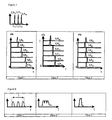
- Figure 3 is a table showing three illustrations of DMD graphs for three different multimode fibres used with a multimode source.
- Fibre 2 of Figure 3 shows a substantially aligned DMD graph; i.e. each pulse exhibits the same delay after a given length of fibre regardless of the radial point of injection of the signal (r/a). The modal dispersion is therefore virtually zero for the wavelength of the source used.
- fibres 1 and 3 do not exhibit an aligned DMD graph; i.e. these fibres exhibit a significant modal dispersion for the wavelength of the source used. These fibres 1 and 3 therefore have an effective modal bandwidth (EMB c ) calculated on the basis of their DMD graph which is smaller than the effective modal bandwidth of fibre 2. Fibres 1 and 3 could thus be removed for certain applications and fibre 2 retained.
- EMB c effective modal bandwidth
- Figure 5 shows three illustrations of DMD graphs of the three previous multimode fibres plotted for a polychromatic source presenting three transverse modes having three distinct wavelengths (it is understood that the source could have more than three transverse modes; the description being limited to three for obvious reasons of clarity of the disclosure).
- Figure 6 is a table illustrating the broadening of the light pulse at the output of each fibre.
- fibre 1 exhibits a substantially aligned DMD graph; i.e. each pulse has the same delay after a given length of fibre regardless of the radial point of injection of the signal (r/a).
- the chromatic dispersion has made it possible to compensate for the modal dispersion.
- the different source modes do not have exactly the same propagation wavelength and consequently the chromatic dispersion of the fibre induces an additional difference in group velocity between the modes of the fibre.
- a modal dispersion is therefore induced in the fibre by the chromatic dispersion (MDICD) when the light signal injected at the input has several transverse modes each having a different wavelength.
- MDICD chromatic dispersion
- This modal dispersion induced by the chromatic dispersion will be added to the modal dispersion induced by the index profile. It is independent of the profile of the fibre since the chromatic dispersion essentially depends on the material of the optical wave guide.
- Fibre 1 which exhibited a non-zero modal dispersion ( Figure 3 ) with a multimode source, has a minimum equivalent modal dispersion ( Figures 5 and 6 ).
- equivalent modal dispersion is meant the delay taking into account the chromatic dispersion.
- fibre 2 which had a virtually zero modal dispersion with a multimode source ( Figure 3 ), has a more significant equivalent modal dispersion due to the modal dispersion induced by the chromatic dispersion (MDICD). This equivalent modal dispersion becomes unacceptable in the case of fibre 3.
- MDICD chromatic dispersion
- fibres 1 and 3 would have been rejected for certain applications in which a broad bandwidth is sought because their effective modal bandwidth calculated from the DMD graph (EMBc) would have been considered below the recommendations of the standards applicable to Ethernet networks.
- EMBc effective modal bandwidth calculated from the DMD graph
- any multimode fibre having an effective modal bandwidth EMB c less than 4700 MHz-km is rejected for application to Ethernet networks having a data rate greater than 10 GbE over more than 550 m. It is however understood that other threshold values can be chosen according to the standards in force and the applications envisaged.
- fibre 1 could be used in an optical system using a transverse multimode source with a minimized equivalent modal dispersion and consequently a satisfactory effective bandwidth of the system.
- fibre 3 must be rejected and fibre 2 does not allow an effective system bandwidth as significant as assumed when it is used with a transverse multimode source.
- the invention proposes an optical system making it possible to achieve a significant effective bandwidth with polychromatic sources emitting multiple transverse modes. None of the modes emitted by the source is filtered; the relative noise of the system is thus not increased.
- the invention proposes to modify the distribution of the energy coupling of the transverse modes emitted by the source in the propagation modes of the fibre in order to exploit the modal dispersion induced by the chromatic dispersion (MDICD) or to limit its impact on the equivalent modal dispersion.
- MDICD chromatic dispersion
- Figure 4 diagrammatically illustrates such an optical system according to the invention.
- Figure 4 shows an optical source 10, which is a polychromatic source emitting a plurality of transverse modes, for example a VCSEL or a light-emitting diode (LED).
- Figure 4 also shows an optical receiver 30 and an optical link comprising a multimode optical fibre 50.
- Figure 4 also shows an optical device 20 which is positioned between the source 10 and the input of the multimode fibre 50. This optical device 20 is suitable for modifying the spatial distribution of the transverse modes emitted by the source.
- the higher-order modes of the source having smaller wavelengths, will not necessarily be coupled only in the high-order modes of the fibre.
- the higher-order modes of the fibres will thus mostly not carry the lowest wavelengths of the spectrum: the chromatic dispersion can then compensate or attenuate the modal dispersion.
- Figures 7 and 8 illustrate a first embodiment of the invention.
- the optical device modifying the distribution of the energy coupling of the transverse modes emitted by the source in the propagation modes of the fibre makes it possible to couple the energy of a source mode (for example the fundamental mode LP 01 , respectively the higher-order mode LP 21 ) in a mode of a different order in the fibre (for example the mode LP 21 , respectively the mode LP 01 ) '
- a source mode for example the fundamental mode LP 01 , respectively the higher-order mode LP 21
- Such an optical device can be a phase mask for example, produced by diffractive optics, an additional micro-lens, a Bragg grating engraved on the source or the fibre, or a mode scrambler.
- a connector of the APC (Angle Polished Connector) type could also be used. It will be appreciated by the skilled reader, that any other optical device that enables changing or re-arranging the spatial distribution or position of the transverse modes may be used to
- fibre 3 which had a significant equivalent modal dispersion when used with a transverse multimode source ( Figures 5 and 6 ), has a minimum equivalent modal dispersion ( Figures 7 and 8 ) when the energy of the fundamental mode of the source is coupled in a higher-order mode of the fibre.
- the modification of the distribution of the coupling of the transverse modes emitted by the source in the propagation modes of the fibre makes it possible to compensate for the modal dispersion due to the profile of the multimode fibre by the modal dispersion induced by the chromatic dispersion.
- fibre 1 it is noted that this modification of the distribution of the coupling of the transverse modes emitted by the source in the propagation modes of the fibre leads to a net increase in the equivalent modal dispersion.
- the modal dispersion induced by the chromatic dispersion is added to the modal dispersion due to the profile of the fibre.
- An optical system according to the invention using fibre 1 with a polychromatic multimode source would not make it possible to achieve a satisfactory effective bandwidth for high-bandwidth Ethernet applications.
- the invention thus makes it possible to use a multimode optical fibre having an effective modal bandwidth of less than 4700 MHz-km - and which would thus have been rejected for many applications - in an optical system comprising a transverse multimode optical source with an optical device suitable for modifying the distribution of the energy coupling of the transverse modes emitted by the source in the propagation modes of the fibre.
- the effective bandwidth of the system is thus greater than 6000 MHz-km despite a limited modal bandwidth of the fibre.
- Figures 9 to 10 illustrate a second embodiment of the invention.
- the optical device modifying the distribution of the energy coupling of the transverse modes emitted by the source in the propagation modes of the fibre makes it possible to mix the different transverse modes emitted by the source in order to broaden the radial positions of each coupled mode in the multimode fibre.
- the energy of the different transverse modes of the source is then distributed over several propagation modes in the fibre.
- Such an optical device can be produced by diffractive optics, an additional micro-lens, a Bragg grating engraved on the source or the fibre, or a mode scrambler.
- a connector of the APC (Angle Polished Connector) type could also be used. It will be appreciated by the skilled reader, that any other optical device that enables changing or re-arranging the spatial distribution or position of the transverse modes may be used to achieve the results of the invention.
- fibres 1 to 3 each have a similar equivalent modal dispersion ( Figure 10 ).
- the energy of each mode emitted by the source is coupled in several (even all) of the propagation modes in the fibre; the chromatic dispersion thus affects each mode of transmission in substantially the same fashion and the modal dispersion induced by the chromatic dispersion (MDICD) acts to attenuate the modal dispersion due to the profile of the fibre.
- MDICD modal dispersion induced by the chromatic dispersion
- the effective bandwidth obtained is less than that obtained in the case where the chromatic dispersion acts to compensate the modal dispersion.
- the invention allows a system using such an optical device suitable for distributing the energy coupling of a transverse mode of the source in a plurality of propagation modes of fibre 1 or fibre 3 - fibres which would have been rejected for many applications on the basis of the standard measurement of their DMD.
- the invention thus makes it possible to use a multimode optical fibre having an effective modal bandwidth of less than 4700 MHz-km - and which would thus have been rejected for many applications - in an optical system comprising a transverse multimode optical source with an optical device suitable for modifying the distribution of the energy coupling of the transverse modes emitted by the source in the propagation modes of the fibre.
- the effective bandwidth of the system is thus greater than 6000 MHz-km despite a limited modal bandwidth of the fibre.
- the maximum spectral width of the source can be comprised between 1 nm and 2 nm.
- Most of the commercially available VCSELs have an RMS (Root Mean Square) spectral width measured as a standard deviation relative to the wavelength of greatest power comprised between 0 and 0.45 nm; a value ⁇ RMS of 0.45 nm would lead to a maximum spectral width ⁇ max of the order of 2 nm.
- Multimode fibres are typically used for short-distance applications and local networks; the fibre lengths typically used are comprised between a few metres and several hundred metres. In such a context, the modal dispersion induced by the chromatic dispersion nevertheless remains limited.
- the invention makes it possible to use low-cost transverse multimode optical sources for producing high-bandwidth Ethernet transmission networks having very good performances, with a product of distance by Gigabit Ethernet data rate which is larger than 3000 Gb/s.m and a binary error rate (BER) of approximately 10 -12 .
- the "distance by Gigabit Ethernet data rate" product corresponds to the length of the multimode fibre used multiplied by the Ethernet data rate of the system.
- the description refers to multimode optical fibres with a graded index having a standardized core diameter of 50 ⁇ m, but it is understood that the invention is applicable to any type of multimode fibre used in an optical system as claimed.
Landscapes
- Physics & Mathematics (AREA)
- Electromagnetism (AREA)
- Engineering & Computer Science (AREA)
- Computer Networks & Wireless Communication (AREA)
- Signal Processing (AREA)
- Optical Communication System (AREA)
- Optical Couplings Of Light Guides (AREA)
Abstract
Description
- The present invention relates to the field of transmissions by optical fibre, and more specifically, short-distance optical transmission systems requiring a broad bandwidth.
- Multimode fibres are commonly used for short-distance applications and local networks. The core of a multimode fibre generally has a diameter of approximately 50 µm and a numerical aperture greater than 0.2, compared to 8 to 9 µm and 0.12 for the core of a single-mode fibre. Thus, for a particular wavelength, several optical modes propagate simultaneously along the fibre, carrying the same information. The bandwidth is directly linked to the group velocity of the optical modes propagating in the multimode core of the fibre. In order to guarantee a broad bandwidth, it is necessary for the group velocities of all the modes to be identical; in other words for the intermodal dispersion, i.e. the difference in group velocity between the slowest mode and the fastest mode to be zero, or at least minimized, for a particular wavelength. Multimode fibres have been the subject of international standardization under standard ITU-T G.651 which in particular defines criteria for bandwidths, numerical aperture, core diameter which relate to the requirements for compatibility between fibres.
- In order to reduce the intermodal dispersion in a multimode fibre, it has been proposed since the 1970s to produce fibres having a graded index with a parabolic core profile. Such a fibre has been used for many years and its characteristics have been described in particular in the publications "Multimode theory of graded-core fibres" by D.Gloge et al., Bell System Technical Journal 1973, pp 1563-1578, and "Pulse broadening in graded-index optical fibers" by Olshansky et al., Applied Optics, Vol. 15, No. 2, Feb 1976.
- A graded-index profile can be defined by a relationship between the index value n at a point as a function of the distance r from this point to the centre of the fibre:

with α ≥ 1; (α-∞ corresponding to a step index profile);
n1, the maximum index of the multimode core;
a, the radius of the multimode core; and
where no is the minimum index of the multimode core, generally corresponding to the index of the cladding (usually made of silica). - A multimode fibre with a graded index therefore has a core profile with a rotational symmetry such that along any radial direction the value of the index decreases continuously from the centre of the fibre to its periphery. These curves are generally representative of the theoretical or set profile of the fibre, whilst the manufacturing constraints of the fibre may result in a slightly different profile.
- When a light signal propagates in such a core having a graded index, the different modes experience a different propagation medium, which affects their speed of propagation differently. By adjusting the value of the parameter α, it is thus possible to theoretically obtain a group velocity which is virtually equal for all the modes and thus a reduced intermodal dispersion for a particular wavelength. A value of the parameter α comprised between 1.8 and 2.2 generally allows a satisfactory limitation of the modal dispersion.
- An optimum value of the parameter α is however valid for a particular wavelength only. Document
US-B-6,363,195 proposes to compensate for the modal dispersion by using a concatenation of multimode fibres in order to optimize the bandwidth for two transmission windows, one centred on 850 nm and the other on 1300 nm. This document proposes to use a length of a first multimode fibre having a value of parameter α1 comprised between 0.8 and 2.1 in order to optimize the bandwidth at 850 nm and a length of a second multimode fibre having a value of parameter α2 comprised between the first value α1 and 8 in order to optimize the bandwidth at 1300 nm. - Furthermore, the exact parameter value α is difficult to control during manufacture of the fibre. In order to compensate the profile deviations from a theoretical profile having an optimum value α, the document
US-B-7,139,457 proposes a concatenation of multimode fibres. The alpha profile of each fibre and the length of each fibre are optimized in order to maximize the bandwidth over a given optical link. - Fibre concatenations for ensuring a compensation of the modal dispersion make the optical systems more complex and increase the cost of these systems. Moreover, these documents are not concerned with the spectral dispersion of the sources used.
- The sources used in optical transmission systems are generally not monochromatic. Thus, the widely-used vertical-cavity surface-emitting lasers, known by the acronym VCSEL, have a wide-spectrum discrete emission. The VCSELs used for high-bandwidth transmissions are generally longitudinally but not transversally single mode, each transverse mode of the laser having its own wavelength corresponding to the various peaks of the emission spectrum. The emission spectrum thus has a spatial and spectral dependence.
- As indicated above, a multimode fibre has an alpha profile with a value of parameter α optimized for a given wavelength. Thus, the introduction of a polychromatic optical signal originating from a transverse multimode source in a multimode fibre causes the appearance of a modal dispersion and consequently a reduction in the bandwidth.
- The document
US-A-2004/0184492 proposes to use only a single one of the transverse modes of a VCSEL source and conditions the emitted signal before its introduction into the multimode fibre. The use of a single transverse mode of a VCSEL source however greatly reduces the power of the emitted signal and leads to a reduction in the power received by an optical receiver at the end of the line, resulting in a reduction in the performance of the optical system. Moreover, filtering part of the transverse modes of the VCSEL increases the relative intensity noise (RIN). On this point reference may be made to the publication of A. Gholami et al., "Optimization of VCSEL Spatiotemporal Operation in MMF Links for 10-Gigabit Ethernet" IEEE Journal of Selected Topics in Quantum Electronics, Vol. 12, No. 4, July/August 2006. - The document
US-A-2005/0078962 proposes to offset the VCSEL output from the centre of the multimode fibre in order to introduce the signal into a "large bandwidth zone". Such an offsetting is however difficult to control and has to be adjusted for each fibre. Moreover, this solution leads to a substantial loss of power in the optical system. - In
GB 2 399 963 - A need therefore exists for an optical system using transverse multimode polychromatic sources which has a broad effective bandwidth without excessive loss of the power emitted by the source.
- To this end, the invention is directed to an optical system comprising:
- a polychromatic optical source (10) for emitting an optical signal comprising a plurality of transverse modes of unique transverse mode order;
- an optical link comprising at least one portion of multimode optical fibre (50);
- an optical device (20) positioned between the optical source (10) and the input of the multimode optical fibre (50),
said optical device being suitable for spatially re-arranging said plurality of transverse modes dependent on said transverse mode order for coupling the energy of each of said transverse modes into a suitable propagation mode for at least partially compensating modal dispersion of said optical link with chromatic dispersion. - The invention proposes a rearrangement of the coupling of the transverse modes emitted by the source in the fibre in order to limit, or even to compensate for, the modal dispersion induced by a polychromatic signal. This rearrangement does not require filtering of the modes emitted by the source; the signal-to-noise ratio of the system is therefore not degraded. The optical device used in the invention is suitable for modifying the distribution of the energy coupling of the transverse modes emitted by the source in the propagation modes of the fibre.
- In an embodiment, the optical device (20) is suitable for coupling the energy of at least one of said transverse modes into at least one suitable propagation mode of said optical link, wherein said transverse mode order of said at least one transverse mode differs from said order of said at least one propagation mode. Here, the optical device is suitable for coupling the energy of a source mode in a propagation mode of a different order in the fibre.
- According to another embodiment, the optical device is suitable for distributing the energy coupling of a transverse mode of the source in a plurality of propagation modes of the fibre.
- According to an embodiment, the multimode fibre has an effective modal bandwidth (EMBc) less than 4700 MHz-km and the system has an effective bandwidth (EB) greater than or equal to 6000 MHz-km.
- According to an embodiment, the source has a maximum spectral width (Δλmax ) comprised between 1 nm and 2 nm. The source can be a surface emitting laser (VCSEL) or a light-emitting diode (LED).
- According to an embodiment, the system has a product of distance by Gigabit Ethernet data rate which is greater than 3000 Gb/s.m.
- Other characteristics and advantages of the invention will become apparent on reading the following description of the embodiments of the invention, given by way of example and with reference to the attached drawings, which show:
-
Figure 1 , an emission spectrum of a VCSEL laser; -
Figure 2 , a schematic diagram showing the calculation of the delay due to the modal dispersion DMD according to the criteria of the standard FOTP-220; -
Figure 3 , a table showing three illustrations of DMD graphs of three multimode fibres plotted for a single mode input light pulse; -
Figure 4 , a schematic representation of an optical system according to the invention; -
Figure 5 , a table showing three illustrations of DMD graphs of the multimode fibres ofFigure 3 plotted for an input light pulse comprising three transverse modes having three separate wavelengths at the output of an optical system not according to the invention ; -
Figure 6 , a table showing schematically the broadening of the light pulse at the output of the optical system ofFigure 5 ; -
Figure 7 , a table showing three illustrations of DMD graphs of the multimode fibres ofFigure 3 plotted for an input light pulse comprising three transverse modes having three separate wavelengths at the output of an optical system according to a first embodiment of the invention ; -
Figure 8 , a table showing schematically the broadening of the light pulse at the output of the optical system ofFigure 7 ; -
Figure 9 , a table showing three illustrations of DMD graphs of the multimode fibres ofFigure 3 plotted for an input light pulse comprising three transverse modes having three separate wavelengths at the output of an optical system according to a second embodiment of the invention ; -
Figure 10 , a table showing schematically the broadening of the light pulse at the output of the optical system ofFigure 9 .
The invention proposes an optimized multimode optical system for use with a polychromatic source having several transverse modes, such as a VCSEL laser.
Figure 1 shows an emission spectrum of a VCSEL laser, with a mode centred on 850 nm for the excitation of the fundamental mode LP01.Figure 1 shows that each transverse mode of the laser has its own wavelength. The maximum RMS spectral width generally authorized for high-bandwidth transmission is 0.45 nm RMS for the VCSELs (as defined in the standard IEEE 802.3ae).
Thus, when the optical signal emitted by the VCSEL is introduced into a multimode fibre, each transverse mode of the VCSEL will diffract differently: the transverse modes of the highest order diverge more rapidly due to their phase and the spatial distribution of their energy, they will therefore be coupled more specifically in the high order modes of the fibre. It will be recalled that the high order modes of the VCSEL occupy the lowest wavelengths in the spectrum. This spectral and spatial distribution of the VCSEL modes results in the highest order modes of the fibres mostly carrying the lowest wavelengths in the spectrum: the chromatic dispersion will therefore further delay the higher-order modes relative to the delay of the fundamental mode.
In fact, a multimode fibre typically has a chromatic dispersion of the order of -100 ps/nm-km at a wavelength of 850 nm. The chromatic dispersion can vary between -80 and -120 ps/nm-km in the spectral range 840-860 nm. This chromatic dispersion will induce a modal dispersion by further delaying the higher-order modes of the fibre which have lower wavelengths since they are mainly excited by the transverse modes having the greatest divergences and therefore also the lowest wavelengths; this dispersion is totally independent of the modal dispersion since the chromatic dispersion depends on the material whereas the modal dispersion depends on the profile of the fibre.
The chromatic dispersion will thus introduce a modal dispersion referred to by the acronym MDICD for "Modal Dispersion Induced by Chromatic Dispersion", resulting in a limitation of the bandwidth.
The modal dispersion induced by the chromatic dispersion can be expressed according to the following equation:
with Δt, the modal dispersion of the light pulse;
λ RMS, which represents a half-width of the emission spectrum of the source;
D, the chromatic dispersion in the multimode fibre, typically -100 ps/nm-km at 850 nm ; and
L, the length of the fibre considered. - Now, for high-bandwidth Ethernet transmission network applications over large distances, in particular for data rates larger than or equal to 10 GbE (10 Gb/s) over more than 300 m (respectively 550 m), it is necessary to guarantee an effective bandwidth larger than or equal to 2000 MHz-km (respectively 4700m MHz-km). Standard TIA-492AAAC-A specifies the required performances for 50 µm diameter high-bandwidth multimode fibres. In the case of multimode fibres, the bandwidth depends on the source used. The effective modal bandwidth (EMB) corresponds to the bandwidth of the source-fibre pair when the chromatic dispersion is disregarded. The effective bandwidth (denoted by the acronym EB) corresponds to the bandwidth of the fibre when the modal dispersion and the chromatic dispersion are taken into account.
- In a manner known per se, the effective modal bandwidth EMB can be estimated by a measurement of the delay due to the modal dispersion, known under the acronym DMD for "Dispersion Mode Delay" graphical representation. The DMD measurement procedure has been the subject of standardization (IEC 60793-1-49 and FOTP-220). To carry out this measurement, care is generally taken to use a source or a fibre length such that the chromatic dispersion is effectively negligeable: the purpose is to characterize the modal dispersion of the fibre.
-
Figure 2 illustrates a schematic diagram of the calculation of the delay due to the modal dispersion DMD according to the criteria of the standard FOTP-220 as published in its version TIA SCFO-6.6 of 22nd November 2002. - A DMD graphical representation is obtained by injecting a light pulse having a given wavelength λ0 at the centre of the fibre and by measuring the pulse delay after a given fibre length L; the introduction of the light pulse of given wavelength λ0 being radially offset to cover the entire core of the multimode fibre.
- The light pulse is injected at different radial positions (r1, r2, r3, r4) with respect to the centre of the multimode optical fibre core. The width of the pulse ΔTref is measured at a quarter of the height generally at the output of the fibre of length L. The delay due to the modal dispersion DMDinner&outer is then measured between a first point in time tinner at a quarter of the height of the leading edge of the first trace r1 and a second point in time touter at a quarter of the height of the trailing edge of the last trace r4. The value of DMDinner&outer is then defined according to the following equation :

- When the parameter α of the multimode fibre is set to an optimum value αoptimum, there is virtually no shift in the light pulse delay for a given wavelength λ0 regardless of the radius r along which the pulse propagates; the intermodal dispersion is low and the effective modal bandwidth is significant. However, this alignment on the DMD graphical representation of the light pulse delays, regardless of the radius r, are valid only for a given wavelength λ0 for a given value of parameter α, αoptimum.
-
Figure 3 is a table showing three illustrations of DMD graphs for three different multimode fibres used with a multimode source. -
Fibre 2 ofFigure 3 shows a substantially aligned DMD graph; i.e. each pulse exhibits the same delay after a given length of fibre regardless of the radial point of injection of the signal (r/a). The modal dispersion is therefore virtually zero for the wavelength of the source used. On theother hand fibres fibres fibre 2.Fibres fibre 2 retained. - However, when a polychromatic source having several transverse modes is used, a modal dispersion is introduced despite the optimization of parameter α.
Figure 5 shows three illustrations of DMD graphs of the three previous multimode fibres plotted for a polychromatic source presenting three transverse modes having three distinct wavelengths (it is understood that the source could have more than three transverse modes; the description being limited to three for obvious reasons of clarity of the disclosure).Figure 6 is a table illustrating the broadening of the light pulse at the output of each fibre. - It is then noted that
fibre 1 exhibits a substantially aligned DMD graph; i.e. each pulse has the same delay after a given length of fibre regardless of the radial point of injection of the signal (r/a). In the case offibre 1, the chromatic dispersion has made it possible to compensate for the modal dispersion. In fact, the different source modes do not have exactly the same propagation wavelength and consequently the chromatic dispersion of the fibre induces an additional difference in group velocity between the modes of the fibre. A modal dispersion is therefore induced in the fibre by the chromatic dispersion (MDICD) when the light signal injected at the input has several transverse modes each having a different wavelength. This modal dispersion induced by the chromatic dispersion will be added to the modal dispersion induced by the index profile. It is independent of the profile of the fibre since the chromatic dispersion essentially depends on the material of the optical wave guide. -
Fibre 1, which exhibited a non-zero modal dispersion (Figure 3 ) with a multimode source, has a minimum equivalent modal dispersion (Figures 5 and 6 ). By "equivalent modal dispersion" is meant the delay taking into account the chromatic dispersion. - On the other hand, it is noted in
Figures 5 and 6 thatfibre 2 which had a virtually zero modal dispersion with a multimode source (Figure 3 ), has a more significant equivalent modal dispersion due to the modal dispersion induced by the chromatic dispersion (MDICD). This equivalent modal dispersion becomes unacceptable in the case offibre 3. - In practice,
fibres - Now, it is noted from
Figures 5 and 6 thatfibre 1 could be used in an optical system using a transverse multimode source with a minimized equivalent modal dispersion and consequently a satisfactory effective bandwidth of the system. On the other hand,fibre 3 must be rejected andfibre 2 does not allow an effective system bandwidth as significant as assumed when it is used with a transverse multimode source. - The invention proposes an optical system making it possible to achieve a significant effective bandwidth with polychromatic sources emitting multiple transverse modes. None of the modes emitted by the source is filtered; the relative noise of the system is thus not increased.
- To this end, the invention proposes to modify the distribution of the energy coupling of the transverse modes emitted by the source in the propagation modes of the fibre in order to exploit the modal dispersion induced by the chromatic dispersion (MDICD) or to limit its impact on the equivalent modal dispersion.
-
Figure 4 diagrammatically illustrates such an optical system according to the invention.Figure 4 shows anoptical source 10, which is a polychromatic source emitting a plurality of transverse modes, for example a VCSEL or a light-emitting diode (LED).Figure 4 also shows anoptical receiver 30 and an optical link comprising a multimodeoptical fibre 50.Figure 4 also shows anoptical device 20 which is positioned between thesource 10 and the input of themultimode fibre 50. Thisoptical device 20 is suitable for modifying the spatial distribution of the transverse modes emitted by the source. - Thus, due to the presence of the
optical device 20, the higher-order modes of the source, having smaller wavelengths, will not necessarily be coupled only in the high-order modes of the fibre. The higher-order modes of the fibres will thus mostly not carry the lowest wavelengths of the spectrum: the chromatic dispersion can then compensate or attenuate the modal dispersion. -
Figures 7 and 8 illustrate a first embodiment of the invention. In this embodiment, the optical device modifying the distribution of the energy coupling of the transverse modes emitted by the source in the propagation modes of the fibre makes it possible to couple the energy of a source mode (for example the fundamental mode LP01, respectively the higher-order mode LP21) in a mode of a different order in the fibre (for example the mode LP21, respectively the mode LP01)' Such an optical device can be a phase mask for example, produced by diffractive optics, an additional micro-lens, a Bragg grating engraved on the source or the fibre, or a mode scrambler. A connector of the APC (Angle Polished Connector) type could also be used. It will be appreciated by the skilled reader, that any other optical device that enables changing or re-arranging the spatial distribution or position of the transverse modes may be used to achieve the results of the invention. - It can thus be noted that
fibre 3, which had a significant equivalent modal dispersion when used with a transverse multimode source (Figures 5 and 6 ), has a minimum equivalent modal dispersion (Figures 7 and 8 ) when the energy of the fundamental mode of the source is coupled in a higher-order mode of the fibre. In this embodiment, the modification of the distribution of the coupling of the transverse modes emitted by the source in the propagation modes of the fibre makes it possible to compensate for the modal dispersion due to the profile of the multimode fibre by the modal dispersion induced by the chromatic dispersion. - On the other hand, in the case of
fibre 1, it is noted that this modification of the distribution of the coupling of the transverse modes emitted by the source in the propagation modes of the fibre leads to a net increase in the equivalent modal dispersion. In the case offibre 1, the modal dispersion induced by the chromatic dispersion is added to the modal dispersion due to the profile of the fibre. An optical system according to theinvention using fibre 1 with a polychromatic multimode source would not make it possible to achieve a satisfactory effective bandwidth for high-bandwidth Ethernet applications. - The invention thus makes it possible to use a multimode optical fibre having an effective modal bandwidth of less than 4700 MHz-km - and which would thus have been rejected for many applications - in an optical system comprising a transverse multimode optical source with an optical device suitable for modifying the distribution of the energy coupling of the transverse modes emitted by the source in the propagation modes of the fibre. The effective bandwidth of the system is thus greater than 6000 MHz-km despite a limited modal bandwidth of the fibre.
-
Figures 9 to 10 illustrate a second embodiment of the invention. In this embodiment, the optical device modifying the distribution of the energy coupling of the transverse modes emitted by the source in the propagation modes of the fibre makes it possible to mix the different transverse modes emitted by the source in order to broaden the radial positions of each coupled mode in the multimode fibre. The energy of the different transverse modes of the source is then distributed over several propagation modes in the fibre. Such an optical device can be produced by diffractive optics, an additional micro-lens, a Bragg grating engraved on the source or the fibre, or a mode scrambler. A connector of the APC (Angle Polished Connector) type could also be used. It will be appreciated by the skilled reader, that any other optical device that enables changing or re-arranging the spatial distribution or position of the transverse modes may be used to achieve the results of the invention. - Thus it is noted that
fibres 1 to 3 each have a similar equivalent modal dispersion (Figure 10 ). In this embodiment, the energy of each mode emitted by the source is coupled in several (even all) of the propagation modes in the fibre; the chromatic dispersion thus affects each mode of transmission in substantially the same fashion and the modal dispersion induced by the chromatic dispersion (MDICD) acts to attenuate the modal dispersion due to the profile of the fibre. - According to this second embodiment, the effective bandwidth obtained is less than that obtained in the case where the chromatic dispersion acts to compensate the modal dispersion. On the other hand, the invention allows a system using such an optical device suitable for distributing the energy coupling of a transverse mode of the source in a plurality of propagation modes of
fibre 1 or fibre 3 - fibres which would have been rejected for many applications on the basis of the standard measurement of their DMD. - The invention thus makes it possible to use a multimode optical fibre having an effective modal bandwidth of less than 4700 MHz-km - and which would thus have been rejected for many applications - in an optical system comprising a transverse multimode optical source with an optical device suitable for modifying the distribution of the energy coupling of the transverse modes emitted by the source in the propagation modes of the fibre. The effective bandwidth of the system is thus greater than 6000 MHz-km despite a limited modal bandwidth of the fibre.
- The maximum spectral width of the source can be comprised between 1 nm and 2 nm. Most of the commercially available VCSELs have an RMS (Root Mean Square) spectral width measured as a standard deviation relative to the wavelength of greatest power comprised between 0 and 0.45 nm; a value λRMS of 0.45 nm would lead to a maximum spectral width Δλmax of the order of 2 nm.
- Multimode fibres are typically used for short-distance applications and local networks; the fibre lengths typically used are comprised between a few metres and several hundred metres. In such a context, the modal dispersion induced by the chromatic dispersion nevertheless remains limited.
- The invention makes it possible to use low-cost transverse multimode optical sources for producing high-bandwidth Ethernet transmission networks having very good performances, with a product of distance by Gigabit Ethernet data rate which is larger than 3000 Gb/s.m and a binary error rate (BER) of approximately 10-12. The "distance by Gigabit Ethernet data rate" product corresponds to the length of the multimode fibre used multiplied by the Ethernet data rate of the system.
- The description refers to multimode optical fibres with a graded index having a standardized core diameter of 50 µm, but it is understood that the invention is applicable to any type of multimode fibre used in an optical system as claimed.
Claims (9)
- An optical system comprising:- a polychromatic optical source (10) for emitting an optical signal comprising a plurality of transverse modes of unique transverse mode order;- an optical link comprising at least one portion of multimode optical fibre (50);- an optical device (20) positioned between the optical source (10) and the input of the multimode optical fibre (50),
said optical device being suitable for spatially re-arranging said plurality of transverse modes dependent on said transverse mode order for coupling the energy of each of said transverse modes into a suitable propagation mode for at least partially compensating modal dispersion of said optical link with chromatic dispersion. - The system of claim 1, in which the optical device (20) is suitable for coupling the energy of at least one of said transverse modes into at least one suitable propagation mode of said optical link, wherein said transverse mode order of said at least one transverse mode differs from said order of said at least one propagation mode.
- The system according to any of the claims 1 or 2, wherein said order of transverse modes is reversed by said optical device in respect to said order of propagation modes of said optical link.
- The system according to any of the previous claims, wherein the optical device (20) is suitable for coupling said optical signal for distributing the energy of a transverse mode in a plurality of propagation modes of the fibre.
- The system of one of the previous claims, in which the multimode fibre has an effective modal bandwidth (EMBc) of less than 4700 MHz-km and the system has an effective bandwidth (EB) of larger than or equal to 6000 MHz-km.
- The system of one of the previous claims, in which the source (10) has a maximum spectral width (Δλmax) comprised between 1 nm and 2 nm.
- The system of one of the previous claims, in which the source (10) is a surface emitting laser (VCSEL) or a light-emitting diode (LED).
- The system of one of the previous claims, having a product of distance by Gigabit Ethernet data rate which is larger than 3000 Gb/s.m.
- The system of one of the previous claims, wherein said optical device comprises at least one element of a group comprising a phase mask, in particular a phase mask produced by diffractive optics, a micro-lens, a Bragg grating, in particular a Bragg grating engraved on said source or on said fibre, a mode scrambler, and a connector of the Angle Polished Connector (APC) type.
Applications Claiming Priority (1)
| Application Number | Priority Date | Filing Date | Title |
|---|---|---|---|
| FR0806238A FR2938389B1 (en) | 2008-11-07 | 2008-11-07 | MULTIMODE OPTICAL SYSTEM |
Publications (2)
| Publication Number | Publication Date |
|---|---|
| EP2184868A1 true EP2184868A1 (en) | 2010-05-12 |
| EP2184868B1 EP2184868B1 (en) | 2011-10-26 |
Family
ID=40766064
Family Applications (1)
| Application Number | Title | Priority Date | Filing Date |
|---|---|---|---|
| EP09013815A Active EP2184868B1 (en) | 2008-11-07 | 2009-11-03 | Multimode optical system |
Country Status (6)
| Country | Link |
|---|---|
| US (1) | US8630545B2 (en) |
| EP (1) | EP2184868B1 (en) |
| CN (1) | CN101738688B (en) |
| AT (1) | ATE531145T1 (en) |
| DK (1) | DK2184868T3 (en) |
| FR (1) | FR2938389B1 (en) |
Cited By (2)
| Publication number | Priority date | Publication date | Assignee | Title |
|---|---|---|---|---|
| US8630545B2 (en) | 2008-11-07 | 2014-01-14 | Draka Comteq, B.V. | Multimode optical system |
| EP2756339A1 (en) * | 2011-09-16 | 2014-07-23 | Corning Incorporated | Few mode optical fibers for mode division multiplexing |
Families Citing this family (77)
| Publication number | Priority date | Publication date | Assignee | Title |
|---|---|---|---|---|
| US8081853B2 (en) | 2007-11-09 | 2011-12-20 | Draka Comteq, B.V. | Single-fiber drop cables for MDU deployments |
| US8165439B2 (en) | 2007-11-09 | 2012-04-24 | Draka Comteq, B.V. | ADSS cables with high-performance optical fiber |
| US8467650B2 (en) | 2007-11-09 | 2013-06-18 | Draka Comteq, B.V. | High-fiber-density optical-fiber cable |
| US8041167B2 (en) * | 2007-11-09 | 2011-10-18 | Draka Comteq, B.V. | Optical-fiber loose tube cables |
| US8031997B2 (en) | 2007-11-09 | 2011-10-04 | Draka Comteq, B.V. | Reduced-diameter, easy-access loose tube cable |
| US8041168B2 (en) | 2007-11-09 | 2011-10-18 | Draka Comteq, B.V. | Reduced-diameter ribbon cables with high-performance optical fiber |
| US8145026B2 (en) | 2007-11-09 | 2012-03-27 | Draka Comteq, B.V. | Reduced-size flat drop cable |
| DK2187486T3 (en) * | 2008-11-12 | 2014-07-07 | Draka Comteq Bv | Reinforcing optical fiber and method of manufacture |
| US20100154478A1 (en) | 2008-12-01 | 2010-06-24 | Panduit Corp. | Multimode fiber having improved index profile |
| FR2939246B1 (en) * | 2008-12-02 | 2010-12-24 | Draka Comteq France | AMPLIFIER OPTICAL FIBER AND METHOD OF MANUFACTURE |
| FR2939522B1 (en) * | 2008-12-08 | 2011-02-11 | Draka Comteq France | OPTICAL FIBER AMPLIFIER RESISTANT TO IONIZING RADIATION |
| FR2939911B1 (en) * | 2008-12-12 | 2011-04-08 | Draka Comteq France | SOLDERED OPTICAL FIBER, TELECOMMUNICATION CABLE COMPRISING MULTIPLE OPTICAL FIBERS AND METHOD FOR MANUFACTURING SUCH A FIBER |
| NL1036343C2 (en) * | 2008-12-19 | 2010-06-22 | Draka Comteq Bv | METHOD AND APPARATUS FOR MANUFACTURING AN OPTICAL FORM. |
| EP2204681B1 (en) | 2008-12-30 | 2016-03-09 | Draka Comteq B.V. | Optical fibre cable comprising a perforated water-blocking element |
| WO2010077132A1 (en) | 2008-12-31 | 2010-07-08 | Draka Comteq B.V. | Uvled apparatus for curing glass-fiber coatings |
| FR2941539B1 (en) | 2009-01-23 | 2011-02-25 | Draka Comteq France | OPTICAL FIBER MONOMODE |
| FR2941541B1 (en) * | 2009-01-27 | 2011-02-25 | Draka Comteq France | OPTICAL FIBER MONOMODE |
| FR2941540B1 (en) * | 2009-01-27 | 2011-05-06 | Draka Comteq France | MONOMODE OPTICAL FIBER HAVING ENHANCED EFFECTIVE SURFACE |
| US8489219B1 (en) | 2009-01-30 | 2013-07-16 | Draka Comteq B.V. | Process for making loose buffer tubes having controlled excess fiber length and reduced post-extrusion shrinkage |
| US9360647B2 (en) * | 2009-02-06 | 2016-06-07 | Draka Comteq, B.V. | Central-tube cable with high-conductivity conductors encapsulated with high-dielectric-strength insulation |
| FR2942571B1 (en) * | 2009-02-20 | 2011-02-25 | Draka Comteq France | AMPLIFIER OPTICAL FIBER COMPRISING NANOSTRUCTURES |
| FR2942551B1 (en) * | 2009-02-23 | 2011-07-15 | Draka Comteq France | CABLE COMPRISING ELEMENTS TO BE EXTRACTED, METHOD OF EXTRACTING THESE ELEMENTS AND METHOD OF MANUFACTURING THE SAME |
| US8625944B1 (en) | 2009-05-13 | 2014-01-07 | Draka Comteq, B.V. | Low-shrink reduced-diameter buffer tubes |
| US8625945B1 (en) | 2009-05-13 | 2014-01-07 | Draka Comteq, B.V. | Low-shrink reduced-diameter dry buffer tubes |
| FR2946436B1 (en) * | 2009-06-05 | 2011-12-09 | Draka Comteq France | MULTIMODE OPTICAL FIBER WITH LARGE BANDWIDTH WITH AN OPTIMIZED HEAT-SLEEVE INTERFACE |
| US8351027B2 (en) * | 2009-06-15 | 2013-01-08 | Panduit Corp. | Method and metric for selecting and designing multimode fiber for improved performance |
| US20110026889A1 (en) * | 2009-07-31 | 2011-02-03 | Draka Comteq B.V. | Tight-Buffered Optical Fiber Unit Having Improved Accessibility |
| FR2953030B1 (en) | 2009-11-25 | 2011-11-18 | Draka Comteq France | MULTIMODE OPTICAL FIBER WITH LARGE BANDWIDTH WITH AN OPTIMIZED HEAT-SLEEVE INTERFACE |
| FR2953606B1 (en) | 2009-12-03 | 2012-04-27 | Draka Comteq France | MULTIMODE OPTICAL FIBER WITH BROAD BANDWIDTH AND LOW BENDBACK LOSSES |
| FR2953029B1 (en) | 2009-11-25 | 2011-11-18 | Draka Comteq France | MULTIMODE OPTICAL FIBER WITH LARGE BANDWIDTH WITH AN OPTIMIZED HEAT-SLEEVE INTERFACE |
| US9014525B2 (en) | 2009-09-09 | 2015-04-21 | Draka Comteq, B.V. | Trench-assisted multimode optical fiber |
| FR2949870B1 (en) | 2009-09-09 | 2011-12-16 | Draka Compteq France | MULTIMODE OPTICAL FIBER HAVING IMPROVED BENDING LOSSES |
| FR2957153B1 (en) | 2010-03-02 | 2012-08-10 | Draka Comteq France | MULTIMODE OPTICAL FIBER WITH BROAD BANDWIDTH AND LOW BENDBACK LOSSES |
| FR2953605B1 (en) | 2009-12-03 | 2011-12-16 | Draka Comteq France | MULTIMODE OPTICAL FIBER WITH BROAD BANDWIDTH AND LOW BENDBACK LOSSES |
| US8306380B2 (en) * | 2009-09-14 | 2012-11-06 | Draka Comteq, B.V. | Methods and devices for cable insertion into latched-duct conduit |
| FR2950156B1 (en) | 2009-09-17 | 2011-11-18 | Draka Comteq France | MULTIMODE OPTIC FIBER |
| FR2950443B1 (en) * | 2009-09-22 | 2011-11-18 | Draka Comteq France | OPTICAL FIBER FOR SUM FREQUENCY GENERATION AND METHOD FOR MANUFACTURING THE SAME |
| US8805143B2 (en) | 2009-10-19 | 2014-08-12 | Draka Comteq, B.V. | Optical-fiber cable having high fiber count and high fiber density |
| FR2952634B1 (en) * | 2009-11-13 | 2011-12-16 | Draka Comteq France | RARE EARTH DOPED SILICA FIBER WITH LOW DIGITAL OPENING |
| US9042693B2 (en) | 2010-01-20 | 2015-05-26 | Draka Comteq, B.V. | Water-soluble water-blocking element |
| DK2352047T3 (en) * | 2010-02-01 | 2019-11-11 | Draka Comteq Bv | Non-zero dispersion-switched optical fiber with a large effective area |
| EP3399357B1 (en) | 2010-02-01 | 2024-12-11 | Draka Comteq B.V. | Non-zero dispersion shifted optical fiber having a short cutoff wavelength |
| EP2369379B1 (en) * | 2010-03-17 | 2015-05-06 | Draka Comteq B.V. | Fibre optique monomode ayant des pertes par courbures réduites |
| US8693830B2 (en) | 2010-04-28 | 2014-04-08 | Draka Comteq, B.V. | Data-center cable |
| PT2390700T (en) | 2010-05-03 | 2016-10-19 | Draka Comteq Bv | PACKAGED OPTICAL FIBER CABLES |
| DK2388239T3 (en) | 2010-05-20 | 2017-04-24 | Draka Comteq Bv | Curing apparatus using angled UV LEDs |
| US8625947B1 (en) | 2010-05-28 | 2014-01-07 | Draka Comteq, B.V. | Low-smoke and flame-retardant fiber optic cables |
| US8871311B2 (en) | 2010-06-03 | 2014-10-28 | Draka Comteq, B.V. | Curing method employing UV sources that emit differing ranges of UV radiation |
| FR2962230B1 (en) | 2010-07-02 | 2012-07-27 | Draka Comteq France | OPTICAL FIBER MONOMODE |
| US8682123B2 (en) | 2010-07-15 | 2014-03-25 | Draka Comteq, B.V. | Adhesively coupled optical fibers and enclosing tape |
| EP2418183B1 (en) | 2010-08-10 | 2018-07-25 | Draka Comteq B.V. | Method for curing coated glass fibres providing increased UVLED intensitiy |
| US8571369B2 (en) | 2010-09-03 | 2013-10-29 | Draka Comteq B.V. | Optical-fiber module having improved accessibility |
| FR2966256B1 (en) | 2010-10-18 | 2012-11-16 | Draka Comteq France | MULTIMODE OPTICAL FIBER INSENSITIVE TO LOSSES BY |
| US8824845B1 (en) | 2010-12-03 | 2014-09-02 | Draka Comteq, B.V. | Buffer tubes having reduced stress whitening |
| FR2971061B1 (en) | 2011-01-31 | 2013-02-08 | Draka Comteq France | BROAD BANDWIDTH OPTICAL FIBER WITH LOW CURB LOSSES |
| DK2482106T5 (en) | 2011-01-31 | 2014-09-22 | Draka Comteq Bv | Multi-mode fiber |
| PT2678728T (en) | 2011-02-21 | 2018-07-05 | Draka Comteq Bv | Fiber Optic Interconnect Cable |
| EP2495589A1 (en) | 2011-03-04 | 2012-09-05 | Draka Comteq B.V. | Rare earth doped amplifying optical fiber for compact devices and method of manufacturing thereof |
| EP2503368A1 (en) | 2011-03-24 | 2012-09-26 | Draka Comteq B.V. | Multimode optical fiber with improved bend resistance |
| EP2506044A1 (en) | 2011-03-29 | 2012-10-03 | Draka Comteq B.V. | Multimode optical fiber |
| EP2518546B1 (en) | 2011-04-27 | 2018-06-20 | Draka Comteq B.V. | High-bandwidth, radiation-resistant multimode optical fiber |
| ES2438173T3 (en) | 2011-05-27 | 2014-01-16 | Draka Comteq Bv | Single mode fiber optic |
| EP2533082B1 (en) | 2011-06-09 | 2013-12-25 | Draka Comteq BV | Single mode optical fiber |
| DK2541292T3 (en) | 2011-07-01 | 2014-12-01 | Draka Comteq Bv | A multimode optical fiber |
| EP2584388B1 (en) * | 2011-10-20 | 2018-09-19 | Draka Comteq BV | Method of computing an effective bandwidth of a multimode fiber |
| EP2584340A1 (en) | 2011-10-20 | 2013-04-24 | Draka Comteq BV | Hydrogen sensing fiber and hydrogen sensor |
| NL2007831C2 (en) | 2011-11-21 | 2013-05-23 | Draka Comteq Bv | Apparatus and method for carrying out a pcvd deposition process. |
| US8929701B2 (en) | 2012-02-15 | 2015-01-06 | Draka Comteq, B.V. | Loose-tube optical-fiber cable |
| WO2013160714A1 (en) | 2012-04-27 | 2013-10-31 | Draka Comteq Bv | Hybrid single and multimode optical fiber for a home network |
| US9188754B1 (en) | 2013-03-15 | 2015-11-17 | Draka Comteq, B.V. | Method for manufacturing an optical-fiber buffer tube |
| NL2011075C2 (en) | 2013-07-01 | 2015-01-05 | Draka Comteq Bv | Pcvd process with removal of substrate tube. |
| WO2015193694A1 (en) | 2014-06-17 | 2015-12-23 | Draka Comteq Bv | Method for characterizing mode group properties of multimodal light traveling through optical components |
| WO2016034913A1 (en) * | 2014-09-03 | 2016-03-10 | Draka Comteq Bv | Method for qualifying the effective modal bandwidth of a multimode fiber over a wide wavelength range from a single wavelength dmd measurement and method for selecting a high effective modal bandwidth multimode fiber from a batch of multimode fibers |
| CN106571581B (en) * | 2015-10-13 | 2019-02-15 | 中国科学院理化技术研究所 | Optical transverse mode control system and method for controlling optical transverse mode conversion |
| US9909952B2 (en) * | 2016-04-29 | 2018-03-06 | Panduit Corp. | Optical fibers and methods associated therewith |
| EP3273623B1 (en) * | 2016-07-18 | 2024-09-18 | Institut Mines Telecom | Optical fiber transmission link with multimode optical fiber and scrambler |
| GB201801796D0 (en) * | 2018-02-02 | 2018-03-21 | Spi Lasers Uk Ltd | Apparatus and method for laser processing a material |
Citations (7)
| Publication number | Priority date | Publication date | Assignee | Title |
|---|---|---|---|---|
| US6363195B1 (en) | 1997-10-27 | 2002-03-26 | Corning Incorporated | Multimode fiber link dispersion compensator |
| US20040184492A1 (en) | 2003-03-21 | 2004-09-23 | Windover Lisa A. | Method and apparatus to enable adaptive equalization at high bandwidths when using single-mode VCSELs over multimode fibers |
| GB2399963A (en) | 2003-02-05 | 2004-09-29 | Zinwave Ltd | Multiple transverse mode laser transmitters in radio over fibre communication system |
| US20050078962A1 (en) | 2003-08-26 | 2005-04-14 | Rudolf Hofmeister | Offset signal launch in optical fiber |
| WO2005062505A1 (en) * | 2003-12-23 | 2005-07-07 | Cambridge University Technical Services Limited | Multiservice optical communication |
| US7139457B2 (en) | 2003-02-05 | 2006-11-21 | Fujikura Ltd. | Method for compensating modal dispersion in multimode optical fiber transmission path |
| US7194155B1 (en) * | 2004-08-10 | 2007-03-20 | The Board Of Trustees Of The Leland Stanford Junior University | Adaptive control for mitigating interference in a multimode transmission medium |
Family Cites Families (59)
| Publication number | Priority date | Publication date | Assignee | Title |
|---|---|---|---|---|
| US4067642A (en) * | 1976-08-03 | 1978-01-10 | Northern Telecom Limited | Reduction of modal and chromatic material dispersion in a multimode optical fiber |
| US4838643A (en) | 1988-03-23 | 1989-06-13 | Alcatel Na, Inc. | Single mode bend insensitive fiber for use in fiber optic guidance applications |
| US5574816A (en) | 1995-01-24 | 1996-11-12 | Alcatel Na Cable Sytems, Inc. | Polypropylene-polyethylene copolymer buffer tubes for optical fiber cables and method for making the same |
| US5717805A (en) | 1996-06-12 | 1998-02-10 | Alcatel Na Cable Systems, Inc. | Stress concentrations in an optical fiber ribbon to facilitate separation of ribbon matrix material |
| US7322122B2 (en) | 1997-01-15 | 2008-01-29 | Draka Comteq B.V. | Method and apparatus for curing a fiber having at least two fiber coating curing stages |
| FR2760540B1 (en) | 1997-03-10 | 1999-04-16 | Alsthom Cge Alcatel | OPTICAL FIBER CABLE TIGHTENED IN SHEATH |
| US5911023A (en) | 1997-07-10 | 1999-06-08 | Alcatel Alsthom Compagnie Generale D'electricite | Polyolefin materials suitable for optical fiber cable components |
| US5881187A (en) * | 1997-07-29 | 1999-03-09 | Corning Incorporated | Optical waveguide fiber bragg grating |
| US6066397A (en) | 1998-03-31 | 2000-05-23 | Alcatel | Polypropylene filler rods for optical fiber communications cables |
| US6175677B1 (en) | 1998-04-17 | 2001-01-16 | Alcatel | Optical fiber multi-ribbon and method for making the same |
| US6085009A (en) | 1998-05-12 | 2000-07-04 | Alcatel | Water blocking gels compatible with polyolefin optical fiber cable buffer tubes and cables made therewith |
| US6215931B1 (en) | 1999-01-26 | 2001-04-10 | Alcatel | Flexible thermoplastic polyolefin elastomers for buffering transmission elements in a telecommunications cable |
| US6134363A (en) | 1999-02-18 | 2000-10-17 | Alcatel | Method for accessing optical fibers in the midspan region of an optical fiber cable |
| US6381390B1 (en) | 1999-04-06 | 2002-04-30 | Alcatel | Color-coded optical fiber ribbon and die for making the same |
| US6181857B1 (en) | 1999-05-12 | 2001-01-30 | Alcatel | Method for accessing optical fibers contained in a sheath |
| US6314224B1 (en) | 1999-06-18 | 2001-11-06 | Alcatel | Thick-walled cable jacket with non-circular cavity cross section |
| US6334016B1 (en) | 1999-06-30 | 2001-12-25 | Alcatel | Optical fiber ribbon matrix material having optimal handling characteristics |
| US6321012B1 (en) | 1999-08-30 | 2001-11-20 | Alcatel | Optical fiber having water swellable material for identifying grouping of fiber groups |
| US6493491B1 (en) | 1999-09-28 | 2002-12-10 | Alcatel | Optical drop cable for aerial installation |
| US6321014B1 (en) | 1999-11-01 | 2001-11-20 | Alcatel | Method for manufacturing optical fiber ribbon |
| FR2809499B1 (en) | 2000-05-29 | 2003-10-03 | Cit Alcatel | PROTECTIVE SKIN FOR OPTICAL FIBERS |
| US6603908B2 (en) | 2000-08-04 | 2003-08-05 | Alcatel | Buffer tube that results in easy access to and low attenuation of fibers disposed within buffer tube |
| US6618538B2 (en) | 2000-12-20 | 2003-09-09 | Alcatel | Method and apparatus to reduce variation of excess fiber length in buffer tubes of fiber optic cables |
| US6922515B2 (en) | 2000-12-20 | 2005-07-26 | Alcatel | Method and apparatus to reduce variation of excess fiber length in buffer tubes of fiber optic cables |
| US7346244B2 (en) | 2001-03-23 | 2008-03-18 | Draka Comteq B.V. | Coated central strength member for fiber optic cables with reduced shrinkage |
| US7045010B2 (en) | 2001-09-06 | 2006-05-16 | Alcatel | Applicator for high-speed gel buffering of flextube optical fiber bundles |
| US6749446B2 (en) | 2001-10-10 | 2004-06-15 | Alcatel | Optical fiber cable with cushion members protecting optical fiber ribbon stack |
| US6912347B2 (en) | 2002-11-15 | 2005-06-28 | Alcatel | Optimized fiber optic cable suitable for microduct blown installation |
| CN100367054C (en) * | 2003-02-05 | 2008-02-06 | 株式会社藤仓 | Modal Dispersion Compensation Method in Multimode Optical Fiber Transmission Line |
| ATE346316T1 (en) * | 2003-02-10 | 2006-12-15 | Nanoptics Inc | METHOD AND APPARATUS FOR PRODUCING OPTICAL TRANSMISSION MEDIA |
| US6941049B2 (en) | 2003-06-18 | 2005-09-06 | Alcatel | Fiber optic cable having no rigid strength members and a reduced coefficient of thermal expansion |
| EP1557707B1 (en) | 2004-01-26 | 2007-12-05 | Draka Comteq B.V. | Buffer tube coupling coil and method of installing a fiber optic cable |
| US7515795B2 (en) | 2005-07-20 | 2009-04-07 | Draka Comteq B.V. | Water-swellable tape, adhesive-backed for coupling when used inside a buffer tube |
| US8135252B2 (en) | 2005-07-20 | 2012-03-13 | Draka Comteq B.V. | Grease-free buffer optical fiber buffer tube construction utilizing a water-swellable, texturized yarn |
| US7567739B2 (en) | 2007-01-31 | 2009-07-28 | Draka Comteq B.V. | Fiber optic cable having a water-swellable element |
| US7599589B2 (en) | 2005-07-20 | 2009-10-06 | Draka Comteq B.V. | Gel-free buffer tube with adhesively coupled optical element |
| FR2893149B1 (en) | 2005-11-10 | 2008-01-11 | Draka Comteq France | OPTICAL FIBER MONOMODE. |
| WO2007091879A1 (en) | 2006-02-08 | 2007-08-16 | Draka Comteq B.V. | Optical fiber cable suited for blown installation or pushing installation in microducts of small diameter |
| FR2899693B1 (en) | 2006-04-10 | 2008-08-22 | Draka Comteq France | OPTICAL FIBER MONOMODE. |
| FR2900739B1 (en) | 2006-05-03 | 2008-07-04 | Draka Comteq France | COMPENSATION FIBER OF CHROMATIC DISPERSION |
| FR2904876B1 (en) | 2006-08-08 | 2008-11-21 | Draka Comteq France | FIBER OPTIC TELECOMMUNICATION CABLE |
| FR2908250B1 (en) | 2006-11-03 | 2009-01-09 | Draka Comteq France Sa Sa | COMPENSATION FIBER OF CHROMATIC DISPERSION |
| FR2908525B1 (en) | 2006-11-10 | 2009-06-26 | Draka Comteq France Sa Sa | FIBER OPTIC TELECOMMUNICATION CABLE |
| EP1930753B1 (en) | 2006-12-04 | 2015-02-18 | Draka Comteq B.V. | Optical fiber with high Brillouin threshold power and low bending losses |
| FR2914751B1 (en) | 2007-04-06 | 2009-07-03 | Draka Comteq France | OPTICAL FIBER MONOMODE |
| FR2915002B1 (en) | 2007-04-11 | 2009-11-06 | Draka Comteq France | METHOD FOR ACCESSING ONE OR MORE OPTICAL FIBERS OF A TELECOMMUNICATION CABLE |
| US8600206B2 (en) | 2008-11-07 | 2013-12-03 | Draka Comteq, B.V. | Reduced-diameter optical fiber |
| DK2206001T3 (en) | 2007-11-09 | 2014-07-07 | Draka Comteq Bv | Optical fiber resistant to microbending |
| US20090214167A1 (en) | 2008-02-25 | 2009-08-27 | Draka Comteq B.V. | Optical Cable Buffer Tube with Integrated Hollow Channels |
| FR2929716B1 (en) | 2008-04-04 | 2011-09-16 | Draka Comteq France Sa | OPTICAL FIBER WITH DISPERSION OFFSET. |
| FR2930997B1 (en) | 2008-05-06 | 2010-08-13 | Draka Comteq France Sa | OPTICAL FIBER MONOMODE |
| FR2931253B1 (en) | 2008-05-16 | 2010-08-20 | Draka Comteq France Sa | FIBER OPTIC TELECOMMUNICATION CABLE |
| FR2932932B1 (en) | 2008-06-23 | 2010-08-13 | Draka Comteq France Sa | MULTIPLEX WAVE LENGTH OPTIC SYSTEM WITH MULTIMODE OPTIC FIBERS |
| FR2933779B1 (en) | 2008-07-08 | 2010-08-27 | Draka Comteq France | MULTIMODE OPTIC FIBERS |
| US8401353B2 (en) | 2008-09-12 | 2013-03-19 | Draka Comteq B.V. | Optical fiber cable assembly |
| US7974507B2 (en) | 2008-09-12 | 2011-07-05 | Draka Comteq, B.V. | High-fiber-density optical fiber cable |
| US7970247B2 (en) | 2008-09-12 | 2011-06-28 | Draka Comteq B.V. | Buffer tubes for mid-span storage |
| FR2938389B1 (en) | 2008-11-07 | 2011-04-15 | Draka Comteq France | MULTIMODE OPTICAL SYSTEM |
| US9360647B2 (en) | 2009-02-06 | 2016-06-07 | Draka Comteq, B.V. | Central-tube cable with high-conductivity conductors encapsulated with high-dielectric-strength insulation |
-
2008
- 2008-11-07 FR FR0806238A patent/FR2938389B1/en not_active Expired - Fee Related
-
2009
- 2009-11-03 DK DK09013815.7T patent/DK2184868T3/en active
- 2009-11-03 EP EP09013815A patent/EP2184868B1/en active Active
- 2009-11-03 AT AT09013815T patent/ATE531145T1/en not_active IP Right Cessation
- 2009-11-06 US US12/614,172 patent/US8630545B2/en active Active
- 2009-11-09 CN CN200910174912.XA patent/CN101738688B/en active Active
Patent Citations (7)
| Publication number | Priority date | Publication date | Assignee | Title |
|---|---|---|---|---|
| US6363195B1 (en) | 1997-10-27 | 2002-03-26 | Corning Incorporated | Multimode fiber link dispersion compensator |
| GB2399963A (en) | 2003-02-05 | 2004-09-29 | Zinwave Ltd | Multiple transverse mode laser transmitters in radio over fibre communication system |
| US7139457B2 (en) | 2003-02-05 | 2006-11-21 | Fujikura Ltd. | Method for compensating modal dispersion in multimode optical fiber transmission path |
| US20040184492A1 (en) | 2003-03-21 | 2004-09-23 | Windover Lisa A. | Method and apparatus to enable adaptive equalization at high bandwidths when using single-mode VCSELs over multimode fibers |
| US20050078962A1 (en) | 2003-08-26 | 2005-04-14 | Rudolf Hofmeister | Offset signal launch in optical fiber |
| WO2005062505A1 (en) * | 2003-12-23 | 2005-07-07 | Cambridge University Technical Services Limited | Multiservice optical communication |
| US7194155B1 (en) * | 2004-08-10 | 2007-03-20 | The Board Of Trustees Of The Leland Stanford Junior University | Adaptive control for mitigating interference in a multimode transmission medium |
Non-Patent Citations (5)
| Title |
|---|
| A. GHOLAMI ET AL.: "Optimization of VCSEL Spatiotemporal Operation in MMF Links for 10-Gigabit Ethernet", IEEE JOURNAL OF SELECTED TOPICS IN QUANTUM ELECTRONICS, vol. 12, no. 4, July 2006 (2006-07-01) |
| ASGHAR GHOLAMI ET AL.: "Optimization of VCSEL Spatiotemporal Operation in MMF Links for 10-Gb Ethernet", IEEE JOURNAL OF SELECTED TOPICS IN QUANTUM ELECTRONICS, vol. 12, no. 4, July 2006 (2006-07-01) - August 2006 (2006-08-01), pages 767 - 775, XP002537834 * |
| D.GLOGE ET AL.: "Multimode theory of graded-core fibres", BELL SYSTEM TECHNICAL JOURNAL, 1973, pages 1563 - 1578 |
| KHADIJETOU ET AL.: "Modeling and characterization of VCSEL-based Avionics Full Duplex Ethernet (AFDX) gigabit links", PROCEEDINGS OF THE SPIE, vol. 6908, January 2008 (2008-01-01), pages 69080J-1 - 69080J-9, XP002537835 * |
| OLSHANSKY ET AL.: "Pulse broadening in graded-index optical fibers", APPLIED OPTICS, vol. 15, no. 2, February 1976 (1976-02-01) |
Cited By (2)
| Publication number | Priority date | Publication date | Assignee | Title |
|---|---|---|---|---|
| US8630545B2 (en) | 2008-11-07 | 2014-01-14 | Draka Comteq, B.V. | Multimode optical system |
| EP2756339A1 (en) * | 2011-09-16 | 2014-07-23 | Corning Incorporated | Few mode optical fibers for mode division multiplexing |
Also Published As
| Publication number | Publication date |
|---|---|
| US20100142969A1 (en) | 2010-06-10 |
| EP2184868B1 (en) | 2011-10-26 |
| FR2938389A1 (en) | 2010-05-14 |
| CN101738688B (en) | 2015-07-08 |
| FR2938389B1 (en) | 2011-04-15 |
| CN101738688A (en) | 2010-06-16 |
| US8630545B2 (en) | 2014-01-14 |
| ATE531145T1 (en) | 2011-11-15 |
| DK2184868T3 (en) | 2012-01-09 |
Similar Documents
| Publication | Publication Date | Title |
|---|---|---|
| EP2184868B1 (en) | Multimode optical system | |
| EP2144096B1 (en) | Method for selecting multimode optical fibres | |
| US8483534B2 (en) | Modified refractive index profile for low-dispersion multi-mode fiber | |
| EP2139128B1 (en) | Wavelength multiplexed optical system with multimode optical fibres | |
| KR100526516B1 (en) | Graded-index optical fiber for high bit-rate and local area network | |
| CN103492918B (en) | Hybrid single and multimode optical fiber for a home network | |
| US9791620B2 (en) | High bandwidth multimode optical fiber optimized for multimode and single-mode transmissions | |
| JP2013502615A5 (en) | ||
| US8531654B2 (en) | Method for designing and selecting optical fiber for use with a transmitter optical subassembly | |
| US8977091B2 (en) | Multimode optical fiber systems with adjustable chromatic modal dispersion compensation | |
| CN1914836B (en) | Multimode optical transmission system and multimode optical transmission method | |
| US9075183B2 (en) | Optical fibers with truncated cores | |
| JP2010101669A (en) | Device and method for measuring band of multimode optical fiber | |
| Ali et al. | Design of Multistage Fiber Bragg Grating (FBG) With Variable Filter Parameters | |
| EP2362251B1 (en) | Optical fibers with truncated cores | |
| Bunge et al. | Study of simplified test procedure for 10-GB-Ethernet fibers | |
| Chen et al. | Chromatic Dispersion Compensated 25Gb/s Multimode VCSEL Transmission Assisted with a MMF Jumper |
Legal Events
| Date | Code | Title | Description |
|---|---|---|---|
| PUAI | Public reference made under article 153(3) epc to a published international application that has entered the european phase |
Free format text: ORIGINAL CODE: 0009012 |
|
| AK | Designated contracting states |
Kind code of ref document: A1 Designated state(s): AT BE BG CH CY CZ DE DK EE ES FI FR GB GR HR HU IE IS IT LI LT LU LV MC MK MT NL NO PL PT RO SE SI SK SM TR |
|
| AX | Request for extension of the european patent |
Extension state: AL BA RS |
|
| 17P | Request for examination filed |
Effective date: 20101004 |
|
| 17Q | First examination report despatched |
Effective date: 20101029 |
|
| GRAP | Despatch of communication of intention to grant a patent |
Free format text: ORIGINAL CODE: EPIDOSNIGR1 |
|
| RIN1 | Information on inventor provided before grant (corrected) |
Inventor name: GHOLAMI, ASGHAR Inventor name: SILLARD, PIERRE Inventor name: MOLIN, DENIS Inventor name: LUMINEAU, YVES |
|
| GRAS | Grant fee paid |
Free format text: ORIGINAL CODE: EPIDOSNIGR3 |
|
| GRAA | (expected) grant |
Free format text: ORIGINAL CODE: 0009210 |
|
| AK | Designated contracting states |
Kind code of ref document: B1 Designated state(s): AT BE BG CH CY CZ DE DK EE ES FI FR GB GR HR HU IE IS IT LI LT LU LV MC MK MT NL NO PL PT RO SE SI SK SM TR |
|
| REG | Reference to a national code |
Ref country code: GB Ref legal event code: FG4D |
|
| REG | Reference to a national code |
Ref country code: CH Ref legal event code: EP |
|
| REG | Reference to a national code |
Ref country code: IE Ref legal event code: FG4D |
|
| REG | Reference to a national code |
Ref country code: DK Ref legal event code: T3 |
|
| REG | Reference to a national code |
Ref country code: DE Ref legal event code: R096 Ref document number: 602009003226 Country of ref document: DE Effective date: 20120119 |
|
| REG | Reference to a national code |
Ref country code: NL Ref legal event code: VDEP Effective date: 20111026 |
|
| LTIE | Lt: invalidation of european patent or patent extension |
Effective date: 20111026 |
|
| REG | Reference to a national code |
Ref country code: AT Ref legal event code: MK05 Ref document number: 531145 Country of ref document: AT Kind code of ref document: T Effective date: 20111026 |
|
| PG25 | Lapsed in a contracting state [announced via postgrant information from national office to epo] |
Ref country code: BE Free format text: LAPSE BECAUSE OF FAILURE TO SUBMIT A TRANSLATION OF THE DESCRIPTION OR TO PAY THE FEE WITHIN THE PRESCRIBED TIME-LIMIT Effective date: 20111026 Ref country code: IS Free format text: LAPSE BECAUSE OF FAILURE TO SUBMIT A TRANSLATION OF THE DESCRIPTION OR TO PAY THE FEE WITHIN THE PRESCRIBED TIME-LIMIT Effective date: 20120226 Ref country code: NO Free format text: LAPSE BECAUSE OF FAILURE TO SUBMIT A TRANSLATION OF THE DESCRIPTION OR TO PAY THE FEE WITHIN THE PRESCRIBED TIME-LIMIT Effective date: 20120126 Ref country code: LT Free format text: LAPSE BECAUSE OF FAILURE TO SUBMIT A TRANSLATION OF THE DESCRIPTION OR TO PAY THE FEE WITHIN THE PRESCRIBED TIME-LIMIT Effective date: 20111026 |
|
| PG25 | Lapsed in a contracting state [announced via postgrant information from national office to epo] |
Ref country code: PT Free format text: LAPSE BECAUSE OF FAILURE TO SUBMIT A TRANSLATION OF THE DESCRIPTION OR TO PAY THE FEE WITHIN THE PRESCRIBED TIME-LIMIT Effective date: 20120227 Ref country code: LV Free format text: LAPSE BECAUSE OF FAILURE TO SUBMIT A TRANSLATION OF THE DESCRIPTION OR TO PAY THE FEE WITHIN THE PRESCRIBED TIME-LIMIT Effective date: 20111026 Ref country code: NL Free format text: LAPSE BECAUSE OF FAILURE TO SUBMIT A TRANSLATION OF THE DESCRIPTION OR TO PAY THE FEE WITHIN THE PRESCRIBED TIME-LIMIT Effective date: 20111026 Ref country code: GR Free format text: LAPSE BECAUSE OF FAILURE TO SUBMIT A TRANSLATION OF THE DESCRIPTION OR TO PAY THE FEE WITHIN THE PRESCRIBED TIME-LIMIT Effective date: 20120127 Ref country code: PL Free format text: LAPSE BECAUSE OF FAILURE TO SUBMIT A TRANSLATION OF THE DESCRIPTION OR TO PAY THE FEE WITHIN THE PRESCRIBED TIME-LIMIT Effective date: 20111026 Ref country code: SI Free format text: LAPSE BECAUSE OF FAILURE TO SUBMIT A TRANSLATION OF THE DESCRIPTION OR TO PAY THE FEE WITHIN THE PRESCRIBED TIME-LIMIT Effective date: 20111026 Ref country code: SE Free format text: LAPSE BECAUSE OF FAILURE TO SUBMIT A TRANSLATION OF THE DESCRIPTION OR TO PAY THE FEE WITHIN THE PRESCRIBED TIME-LIMIT Effective date: 20111026 Ref country code: HR Free format text: LAPSE BECAUSE OF FAILURE TO SUBMIT A TRANSLATION OF THE DESCRIPTION OR TO PAY THE FEE WITHIN THE PRESCRIBED TIME-LIMIT Effective date: 20111026 |
|
| PG25 | Lapsed in a contracting state [announced via postgrant information from national office to epo] |
Ref country code: CY Free format text: LAPSE BECAUSE OF FAILURE TO SUBMIT A TRANSLATION OF THE DESCRIPTION OR TO PAY THE FEE WITHIN THE PRESCRIBED TIME-LIMIT Effective date: 20111026 Ref country code: MC Free format text: LAPSE BECAUSE OF NON-PAYMENT OF DUE FEES Effective date: 20111130 |
|
| PG25 | Lapsed in a contracting state [announced via postgrant information from national office to epo] |
Ref country code: SK Free format text: LAPSE BECAUSE OF FAILURE TO SUBMIT A TRANSLATION OF THE DESCRIPTION OR TO PAY THE FEE WITHIN THE PRESCRIBED TIME-LIMIT Effective date: 20111026 Ref country code: BG Free format text: LAPSE BECAUSE OF FAILURE TO SUBMIT A TRANSLATION OF THE DESCRIPTION OR TO PAY THE FEE WITHIN THE PRESCRIBED TIME-LIMIT Effective date: 20120126 Ref country code: CZ Free format text: LAPSE BECAUSE OF FAILURE TO SUBMIT A TRANSLATION OF THE DESCRIPTION OR TO PAY THE FEE WITHIN THE PRESCRIBED TIME-LIMIT Effective date: 20111026 Ref country code: EE Free format text: LAPSE BECAUSE OF FAILURE TO SUBMIT A TRANSLATION OF THE DESCRIPTION OR TO PAY THE FEE WITHIN THE PRESCRIBED TIME-LIMIT Effective date: 20111026 |
|
| REG | Reference to a national code |
Ref country code: IE Ref legal event code: MM4A |
|
| PG25 | Lapsed in a contracting state [announced via postgrant information from national office to epo] |
Ref country code: RO Free format text: LAPSE BECAUSE OF FAILURE TO SUBMIT A TRANSLATION OF THE DESCRIPTION OR TO PAY THE FEE WITHIN THE PRESCRIBED TIME-LIMIT Effective date: 20111026 |
|
| PLBE | No opposition filed within time limit |
Free format text: ORIGINAL CODE: 0009261 |
|
| STAA | Information on the status of an ep patent application or granted ep patent |
Free format text: STATUS: NO OPPOSITION FILED WITHIN TIME LIMIT |
|
| 26N | No opposition filed |
Effective date: 20120727 |
|
| PG25 | Lapsed in a contracting state [announced via postgrant information from national office to epo] |
Ref country code: IE Free format text: LAPSE BECAUSE OF NON-PAYMENT OF DUE FEES Effective date: 20111103 |
|
| REG | Reference to a national code |
Ref country code: DE Ref legal event code: R097 Ref document number: 602009003226 Country of ref document: DE Effective date: 20120727 |
|
| PG25 | Lapsed in a contracting state [announced via postgrant information from national office to epo] |
Ref country code: AT Free format text: LAPSE BECAUSE OF FAILURE TO SUBMIT A TRANSLATION OF THE DESCRIPTION OR TO PAY THE FEE WITHIN THE PRESCRIBED TIME-LIMIT Effective date: 20111026 |
|
| PG25 | Lapsed in a contracting state [announced via postgrant information from national office to epo] |
Ref country code: MT Free format text: LAPSE BECAUSE OF FAILURE TO SUBMIT A TRANSLATION OF THE DESCRIPTION OR TO PAY THE FEE WITHIN THE PRESCRIBED TIME-LIMIT Effective date: 20111026 Ref country code: MK Free format text: LAPSE BECAUSE OF FAILURE TO SUBMIT A TRANSLATION OF THE DESCRIPTION OR TO PAY THE FEE WITHIN THE PRESCRIBED TIME-LIMIT Effective date: 20111026 |
|
| PG25 | Lapsed in a contracting state [announced via postgrant information from national office to epo] |
Ref country code: SM Free format text: LAPSE BECAUSE OF FAILURE TO SUBMIT A TRANSLATION OF THE DESCRIPTION OR TO PAY THE FEE WITHIN THE PRESCRIBED TIME-LIMIT Effective date: 20111026 Ref country code: ES Free format text: LAPSE BECAUSE OF FAILURE TO SUBMIT A TRANSLATION OF THE DESCRIPTION OR TO PAY THE FEE WITHIN THE PRESCRIBED TIME-LIMIT Effective date: 20120206 |
|
| PG25 | Lapsed in a contracting state [announced via postgrant information from national office to epo] |
Ref country code: LU Free format text: LAPSE BECAUSE OF NON-PAYMENT OF DUE FEES Effective date: 20111103 |
|
| PG25 | Lapsed in a contracting state [announced via postgrant information from national office to epo] |
Ref country code: FI Free format text: LAPSE BECAUSE OF FAILURE TO SUBMIT A TRANSLATION OF THE DESCRIPTION OR TO PAY THE FEE WITHIN THE PRESCRIBED TIME-LIMIT Effective date: 20111026 |
|
| PG25 | Lapsed in a contracting state [announced via postgrant information from national office to epo] |
Ref country code: TR Free format text: LAPSE BECAUSE OF FAILURE TO SUBMIT A TRANSLATION OF THE DESCRIPTION OR TO PAY THE FEE WITHIN THE PRESCRIBED TIME-LIMIT Effective date: 20111026 |
|
| PG25 | Lapsed in a contracting state [announced via postgrant information from national office to epo] |
Ref country code: HU Free format text: LAPSE BECAUSE OF FAILURE TO SUBMIT A TRANSLATION OF THE DESCRIPTION OR TO PAY THE FEE WITHIN THE PRESCRIBED TIME-LIMIT Effective date: 20111026 |
|
| REG | Reference to a national code |
Ref country code: CH Ref legal event code: PL |
|
| PG25 | Lapsed in a contracting state [announced via postgrant information from national office to epo] |
Ref country code: CH Free format text: LAPSE BECAUSE OF NON-PAYMENT OF DUE FEES Effective date: 20131130 Ref country code: LI Free format text: LAPSE BECAUSE OF NON-PAYMENT OF DUE FEES Effective date: 20131130 |
|
| REG | Reference to a national code |
Ref country code: FR Ref legal event code: PLFP Year of fee payment: 7 |
|
| REG | Reference to a national code |
Ref country code: FR Ref legal event code: PLFP Year of fee payment: 8 |
|
| REG | Reference to a national code |
Ref country code: FR Ref legal event code: PLFP Year of fee payment: 9 |
|
| PGFP | Annual fee paid to national office [announced via postgrant information from national office to epo] |
Ref country code: DE Payment date: 20251128 Year of fee payment: 17 |
|
| PGFP | Annual fee paid to national office [announced via postgrant information from national office to epo] |
Ref country code: GB Payment date: 20251127 Year of fee payment: 17 |
|
| PGFP | Annual fee paid to national office [announced via postgrant information from national office to epo] |
Ref country code: IT Payment date: 20251119 Year of fee payment: 17 Ref country code: DK Payment date: 20251125 Year of fee payment: 17 |
|
| PGFP | Annual fee paid to national office [announced via postgrant information from national office to epo] |
Ref country code: FR Payment date: 20251125 Year of fee payment: 17 |