EP2184828B1 - A detection circuit and a method for detecting a wrong power line connection - Google Patents
A detection circuit and a method for detecting a wrong power line connection Download PDFInfo
- Publication number
- EP2184828B1 EP2184828B1 EP08019653.8A EP08019653A EP2184828B1 EP 2184828 B1 EP2184828 B1 EP 2184828B1 EP 08019653 A EP08019653 A EP 08019653A EP 2184828 B1 EP2184828 B1 EP 2184828B1
- Authority
- EP
- European Patent Office
- Prior art keywords
- voltage
- relay
- digital signal
- supply voltage
- microcontroller
- Prior art date
- Legal status (The legal status is an assumption and is not a legal conclusion. Google has not performed a legal analysis and makes no representation as to the accuracy of the status listed.)
- Not-in-force
Links
- 238000001514 detection method Methods 0.000 title claims description 49
- 238000000034 method Methods 0.000 title claims description 23
- 238000010411 cooking Methods 0.000 claims description 18
- 230000003287 optical effect Effects 0.000 claims description 6
- 230000006698 induction Effects 0.000 claims description 4
- 230000007935 neutral effect Effects 0.000 description 5
- 230000006378 damage Effects 0.000 description 2
- 238000010586 diagram Methods 0.000 description 2
- 230000033228 biological regulation Effects 0.000 description 1
- 238000010438 heat treatment Methods 0.000 description 1
- 230000002459 sustained effect Effects 0.000 description 1
Images
Classifications
-
- H—ELECTRICITY
- H02—GENERATION; CONVERSION OR DISTRIBUTION OF ELECTRIC POWER
- H02H—EMERGENCY PROTECTIVE CIRCUIT ARRANGEMENTS
- H02H11/00—Emergency protective circuit arrangements for preventing the switching-on in case an undesired electric working condition might result
- H02H11/006—Emergency protective circuit arrangements for preventing the switching-on in case an undesired electric working condition might result in case of too high or too low voltage
Definitions
- the power supply unit, the relay, the detection means, the analogue-digital converter and/or the microcontroller may be components of a synchronisation circuit.
- the synchronisation circuit may be provided to synchronize the frequency of an alternating current voltage. If the residual voltage is continuous, then said synchronisation circuit is an option only. However, if the residual voltage is a sinusoidal signal or suchlike, then the synchronisation circuit is essential.
- the relay cannot be closed, if the supply voltage, the residual voltage and/or the digital signal exceed a predetermined value.
Landscapes
- Supply And Distribution Of Alternating Current (AREA)
- Induction Heating Cooking Devices (AREA)
Description
- The present invention relates to a household appliance with a detection circuit for detecting a wrong power line connection. Further the present invention relates to a method for detecting a wrong power line connection in a household appliance. In particular, the detection circuit and the method according to the present invention are provided for a cooking oven or a cooking hob.
- Some modern household appliances require a high electric power. For example, an electric cooking hob may have a peak power of about 7200 W, and a cavity cooking oven may have a peak power of about 3600 W.
- Power lines in private households have a voltage either of 230 V with one power line or of 230 V / 400 V with three power lines. In first case there is one voltage of 230 V between the single power line and the neutral line. In the second case the voltages between two of the three power lines are 400 V, and the voltages between each of the three power lines on the one hand and the neutral line on the other hand is also 230 V.
- In this second case, the installer or the operator can connect the household appliance to different voltages. However, if a household appliance, which is provided for 230 V, is connected wrongly to the supply voltage of 400 V, then electronic circuits of the household appliances may be destroyed. Thus, a detection circuit is required in order to recognize or detect, if the household appliance is connected to the wrong power line.
- Some conventional household appliances comprise a separate detection circuit for recognizing the wrong power line. Such a detection circuit comprises additional components and is provided to detect a wrong power line connection.
-
US 2007/0159738 A1 discloses a receptacle for power circuit. The receptacle comprises a line terminal for receiving a voltage including one of a nominal voltage and a bigger excessive voltage. Further, the receptacle comprises a load terminal, a neutral terminal, a load neutral terminal and separable contacts electrically connected between the line and load terminals. Additionally, the receptacle comprises an operating mechanism structured to open and close the separable contacts, and a trip mechanism cooperating with the operating mechanism to trip open said separable contacts. The trip mechanism includes an overvoltage circuit for detecting a sustained excessive voltage condition between the neutral terminal and the line or load terminal and for responsively actuating the operating mechanism to trip open the separable contacts. The receptacle comprises a receptacle casing and is formed as a separate device. However, the receptacle comprises a relative high number of components and is complex. - It is an object of the present invention to provide a household appliance with a detection circuit and a method for detecting a wrong power supply connection, wherein said detection circuit and the according method require a reduced number of electronic elements.
- This object of the present invention is achieved by the household appliance with a detection circuit according to claim 1.
- According to the present invention the household appliance with a detection circuit for detecting a wrong power line connection, wherein said detection circuit is integrated within the household appliance, comprises:
- a power supply unit connectable to an external supply voltage,
- at least one relay, wherein the secondary side of said relay is connected to the power supply unit and connectable to the external supply voltage,
- detection means for detecting a residual voltage at the secondary side of the relay, wherein said residual voltage depends on the supply voltage,
- at least one analogue-digital converter for converting the detected residual voltage into a digital signal, wherein an input of the analogue-digital converter is connected to the detection means, and
- at least one microcontroller for processing the digital signal, wherein the microcontroller is connected to an output of the analogue-digital converter, wherein
- the relay is controlled by the microcontroller in order to avoid that the relay will be closed, if the supply voltage, the residual voltage and/or the digital signal exceed a predetermined value, and wherein
- the microcontroller is connected to an acoustic device in order to display an acoustic signal, if the supply voltage, the residual voltage and/or the digital signal exceed the predetermined value.
- The main idea of the present invention is the estimation of the main input alternating current voltage by detecting the residual voltage at the secondary side of the relay. Another central point of the present invention is the use of standard components. Thus, it is not necessary to add any specific components. In particular, a cooking oven and a cooking hob comprise usually the microcontroller, the analogue-digital converter, the power supply unit and the relay. Further, the cooking oven and the cooking hob comprise electric or electronic elements suitable for the detection means. The present invention allows the detection circuit without any additional component. The inventive detection circuit avoids the destruction of electric and electronic components as a result of a wrong power line connection.
- According to the present invention the relay is controlled by the microcontroller in order to avoid that the relay will be closed, if the supply voltage, the residual voltage and/or the digital signal exceed a predetermined value. Thus, the relay cannot be closed, if the voltage of the connected power line is higher than the voltage of the correct power line.
- Additionally the microcontroller may be connected to an optical device in order to display an optical signal, if the supply voltage, the residual voltage and/or the digital signal exceed the predetermined value. In this case the operator will be informed that the device is connected to the wrong power line.
- Further, the power supply unit, the relay, the detection means, the analogue-digital converter and/or the microcontroller may be standard components of the household appliance. Thus, no additional components are required.
- For example, the power supply unit, the relay, the detection means, the analogue-digital converter and/or the microcontroller may be components of an input voltage detection circuit.
- In a similar way, the power supply unit, the relay, the detection means, the analogue-digital converter and/or the microcontroller may be components of a synchronisation circuit. The synchronisation circuit may be provided to synchronize the frequency of an alternating current voltage. If the residual voltage is continuous, then said synchronisation circuit is an option only. However, if the residual voltage is a sinusoidal signal or suchlike, then the synchronisation circuit is essential.
- Preferably, the electric device may be a household appliance. For example, the electric device is a cooking appliance, in particular an induction hob and/or a cooking oven.
- The object of the present invention is further achieved by the method according to claim 6.
- According to the present invention the method for detecting a wrong power line connection is provided for a household appliance and comprises the steps of:
- connecting a power supply unit to an external supply voltage, wherein the secondary side of a relay is connected to the power supply unit and connectable to the external supply voltage,
- detecting a residual voltage at the secondary side of the relay, wherein said residual voltage depends on the supply voltage,
- converting the detected residual voltage into a digital signal, and
- processing the digital signal in order to recognize and/or display the wrong power line connection, wherein
- the relay cannot be closed, if the supply voltage, the residual voltage (UR) and/or the digital signal exceed a predetermined value, and wherein
- an acoustic signal is displayed, if the supply voltage, the residual voltage and/or the digital signal exceed the predetermined value.
- The main idea of the present invention is estimating of the main input alternating current voltage by detecting the residual voltage at the secondary side of the relay. Said residual voltage depends on the supply voltage of the power line connection. The wrong power line connection can be detected, when the relay is open. Another central point of the present invention is the use of standard components, which are usually present in the electric device. Thus, it is not necessary to add any specific components and the method of the present invention allows the detection of wrong power line connection without any additional component. The inventive method avoids the destruction of electric and electronic components as a result of a wrong power line connection.
- According to the present invention the relay cannot be closed, if the supply voltage, the residual voltage and/or the digital signal exceed a predetermined value.
- Additionally, an optical signal is displayed, if the supply voltage, the residual voltage and/or the digital signal exceed the predetermined value.
- Preferably, the method is at least partially performed by standard components of the household appliance. This allows a realization with low costs.
- In particular, the method may be at least partially performed by components of an input voltage detection circuit. Further, the method may be at least partially performed by components of a synchronisation circuit. The synchronisation circuit may be provided to synchronize the frequency of an alternating current voltage. If the residual voltage is continuous, then the synchronisation circuit is only an option. However, if the residual voltage is a sinusoidal signal or suchlike, then the synchronisation circuit is essential.
- According to the preferred embodiment of the present invention, the method is provided for a cooking appliance, in particular an induction hob and/or a cooking oven.
- The novel and inventive features believed to be the characteristic of the present invention are set forth in the appended claims.
- The invention will be described in further detail with reference to the drawing, in which
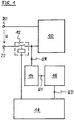
- FIG 1
- illustrates a schematic diagram of a detection circuit for detecting a wrong power line connection according to a preferred embodiment of the present invention.
- The
power supply unit 10 is directly connected to a firstpower input terminal 20. A secondary part of therelay 14 is connected to a secondpower input terminal 22 on a first side and to thepower supply unit 10 on a second side. Thus, the connection between the secondpower input terminal 22 and thepower supply unit 10 is switched by therelay 12. The second side of the secondary part of therelay 12 is connected to the detection means 14. - The detection means 14 are provided to detect a residual voltage UR between the secondary part of the
relay 12 and thepower supply unit 10. The residual voltage UR depends on a supply voltage U between the firstpower input terminal 20 and the secondpower input terminal 22. Thus, the residual voltage UR contains information about the supply voltage U. The detection means 14 provide voltage value UV corresponding with the residual voltage UR. The detection means 14 may be realized by a voltage divider or by a network made of resistor elements. In a special case the voltage value UV may be identical with the residual voltage UR. - The detection means 14 are connected to an input of the analogue-
digital converter 16. The analogue-digital converter 16 receives the voltage value UV and converts it into a corresponding digital signal UD. An output of the analogue-digital converter 16 is connected to themicrocontroller 18. Themicrocontroller 18 processes the digital signal UD. Further, the analogue-digital converter 16 may be an embedded block of themicrocontroller 18. - The
microcontroller 18 is further connected to a primary part of therelay 12. Themicrocontroller 18 avoids that the relay will be closed, if the digital signal UD exceeds a predetermined value. Thus, therelay 12 cannot be closed, if the supply voltage U exceeds a predetermined value. - For example, if the
power supply unit 10 is provided for a supply voltage U of 230 V, but the real supply voltage U is 400 V, then themicrocontroller 18 avoids that therelay 12 can be closed. The wrong supply voltage U may be occur, when an installer or an operator connects the firstpower input terminal 20 and the secondpower input terminal 22 with wrong power lines. - The detection circuit may consist of components, which are already present in the electric device. For example, a direct 50 Hz synchronization circuit or some of its components may be used as a part or the complete detection circuit. Also a voltage detection circuit, which is used for power regulation, may be used as the detection circuit.
- The detection circuit may be realized within the electric device without any additional components. Thus the detection circuit is very cheap and needs no extra space on the board. The
microcontroller 16 does not need any additional pins. The inventive detection circuit has low power consumption. - The detection circuit according to the present invention is able to detect or measure the supply voltage, even if the
relay 12 is open. -
- 10
- power supply unit
- 12
- relay
- 14
- detection means
- 16
- analogue-digital converter
- 18
- microcontroller
- 20
- first power input terminal
- 22
- second power input terminal
- U
- supply voltage
- UR
- residual voltage
- UV
- voltage value
- UD
- digital signal
Claims (10)
- A household appliance with a detection circuit for detecting a wrong power line connection, wherein said detection circuit is integrated within the household appliance and comprises:- a power supply unit (10) connectable to an external supply voltage (U),- at least one relay (12), wherein the secondary side of said relay (12) is connected to the power supply unit (10) and connectable to the external supply voltage,- detection means (14) for detecting a residual voltage (UR) at the secondary side of the relay (12), wherein said residual voltage (UR) depends on the supply voltage (U),- at least one analogue-digital converter (16) for converting the detected residual voltage (UR) into a digital signal (UD), wherein an input of the analogue-digital converter (16) is connected to the detection means (14), and- at least one microcontroller (18) for processing the digital signal (UD), wherein the microcontroller (18) is connected to an output of the analogue-digital converter (14), wherein- the relay (12) is controlled by the microcontroller (18) in order to avoid that the relay (12) will be closed, if the supply voltage (U), the residual voltage (UR) and/or the digital signal (UD) exceed a predetermined value, and wherein- the microcontroller (18) is connected to an acoustic device in order to display an acoustic signal, if the supply voltage (U), the residual voltage (UR) and/or the digital signal (UD) exceed the predetermined value.
- The household appliance according to claim 1,
characterized in, that
the microcontroller (18) is connected to an optical device in order to display an optical signal, if the supply voltage (U), the residual voltage (UR) and/or the digital signal (UD) exceed the predetermined value. - The household appliance according to claim 1 or 2, characterized in, that the power supply unit (10), the relay (12), the detection means (14), the analogue-digital converter (16) and/or the microcontroller (18) are components of an input voltage detection circuit.
- The household appliance according to any one of the preceding claims, characterized in, that the power supply unit (10), the relay (12), the detection means (14), the analogue-digital converter (16) and/or the microcontroller (18) are components of a synchronisation circuit provided for synchronizing the frequency of an alternating current voltage.
- The household appliance according to any one of the preceding claims, characterized in, that the household appliance is an induction hob and/or a cooking oven.
- A method for detecting a wrong power line connection, wherein said method is provided for a household appliance and comprises the steps of:- connecting a power supply unit (10) to an external supply voltage (U), wherein the secondary side of a relay (12) is connected to the power supply unit (10) and connectable to the external supply voltage,- detecting a residual voltage (UR) at the secondary side of the relay (12), wherein said residual voltage (UR) depends on the supply voltage (U),- converting the detected residual voltage (UR) into a digital signal (UD), and- processing the digital signal (UD) in order to recognize and/or display the wrong power line connection, wherein- the relay (12) cannot be closed, if the supply voltage (U), the residual voltage (UR) and/or the digital signal (UD) exceed a predetermined value, and wherein- an acoustic signal is displayed, if the supply voltage (U), the residual voltage (UR) and/or the digital signal (UD) exceed the predetermined value.
- The method according to claim 6,
characterized in, that
an optical signal is displayed, if the supply voltage (U), the residual voltage (UR) and/or the digital signal (UD) exceed the predetermined value. - The method according to claim 6 or 7,
characterized in, that
the method is at least partially performed by components of an input voltage detection circuit. - The method according to any one of the claims 6 to 8,
characterized in, that
the method is at least partially performed by components of a synchronisation circuit provided for synchronizing the frequency of an alternating current voltage. - The method according to any one of the claims 6 to 9,
characterized in, that
the method is provided for an induction hob and/or a cooking oven.
Priority Applications (1)
| Application Number | Priority Date | Filing Date | Title |
|---|---|---|---|
| EP08019653.8A EP2184828B1 (en) | 2008-11-11 | 2008-11-11 | A detection circuit and a method for detecting a wrong power line connection |
Applications Claiming Priority (1)
| Application Number | Priority Date | Filing Date | Title |
|---|---|---|---|
| EP08019653.8A EP2184828B1 (en) | 2008-11-11 | 2008-11-11 | A detection circuit and a method for detecting a wrong power line connection |
Publications (2)
| Publication Number | Publication Date |
|---|---|
| EP2184828A1 EP2184828A1 (en) | 2010-05-12 |
| EP2184828B1 true EP2184828B1 (en) | 2019-04-24 |
Family
ID=40535599
Family Applications (1)
| Application Number | Title | Priority Date | Filing Date |
|---|---|---|---|
| EP08019653.8A Not-in-force EP2184828B1 (en) | 2008-11-11 | 2008-11-11 | A detection circuit and a method for detecting a wrong power line connection |
Country Status (1)
| Country | Link |
|---|---|
| EP (1) | EP2184828B1 (en) |
Families Citing this family (1)
| Publication number | Priority date | Publication date | Assignee | Title |
|---|---|---|---|---|
| JP7723384B2 (en) * | 2021-09-24 | 2025-08-14 | Necプラットフォームズ株式会社 | Misconnection prevention device and misconnection prevention method |
Family Cites Families (4)
| Publication number | Priority date | Publication date | Assignee | Title |
|---|---|---|---|---|
| US5440441A (en) * | 1984-10-24 | 1995-08-08 | Ahuja; Om | Apparatus for protecting, monitoring, and managing an AC/DC electrical line or a telecommunication line using a microprocessor |
| CN1059294C (en) * | 1996-09-05 | 2000-12-06 | 株式会社三社电机制作所 | Overvoltage protection device |
| IT1319740B1 (en) * | 2000-12-29 | 2003-11-03 | Abb Ricerca Spa | LOW VOLTAGE DIFFERENTIAL SWITCH WITH IMPROVED FUNCTIONALITY |
| US20070159738A1 (en) * | 2006-01-09 | 2007-07-12 | Eaton Corporation | Receptacle providing sustained excessive voltage protection |
-
2008
- 2008-11-11 EP EP08019653.8A patent/EP2184828B1/en not_active Not-in-force
Non-Patent Citations (1)
| Title |
|---|
| None * |
Also Published As
| Publication number | Publication date |
|---|---|
| EP2184828A1 (en) | 2010-05-12 |
Similar Documents
| Publication | Publication Date | Title |
|---|---|---|
| EP4032372B1 (en) | Electrical circuit for a cooking appliance and cooking appliance | |
| US9879864B2 (en) | Movable cooking appliance | |
| US20120302092A1 (en) | Multifunctional electricity outlet | |
| KR101641516B1 (en) | The distribution panel including an open phase trip function type zero sequence filter | |
| US10547246B2 (en) | Auxiliary supply for a current supply | |
| CN110691712A (en) | Method of operating vehicle charging device, vehicle charging device and system including sensor device and vehicle charging device | |
| EA001174B1 (en) | EXTENDED ELECTRIC SWITCHING DEVICE | |
| SE1951407A1 (en) | Residual current circuit breaker | |
| US5116232A (en) | Double plug assembly | |
| US11326770B2 (en) | Under cabinet light interface device and lighting device interface device | |
| EP2184828A1 (en) | A detection circuit and a method for detecting a wrong power line connection | |
| KR20120001676A (en) | Input circuit for AC current signal and motor starter including same | |
| EP2195901B1 (en) | A detection circuit and a method for detecting a wrong supply voltage | |
| TW201406006A (en) | Power supply system and method for operating power supply system | |
| US11293994B2 (en) | Earth leakage circuit breaker capable of outputting type of leakage current and method of controlling the same | |
| CN215067204U (en) | Dental instrument detection device and dental instrument | |
| WO2016134776A1 (en) | Polyphase electrical household appliance with improved safety and control method | |
| EP3675290B1 (en) | Electrical outlet and method | |
| PL209302B1 (en) | Control circuit, in particular cooker timer, for cooking appliance | |
| US11245325B2 (en) | Compensation filter and method for activating a compensation filter | |
| JP3972802B2 (en) | Power failure detection unit and power supply | |
| EP2362516A1 (en) | Device for reducing the power consumption of appliances | |
| CN107978139B (en) | Wireless remote control switch device and wireless remote control electric appliance | |
| HK1143006A (en) | A detection circuit and a method for detecting a wrong supply voltage | |
| CN121208603A (en) | Relay adhesion detection circuit, method and electrical equipment |
Legal Events
| Date | Code | Title | Description |
|---|---|---|---|
| PUAI | Public reference made under article 153(3) epc to a published international application that has entered the european phase |
Free format text: ORIGINAL CODE: 0009012 |
|
| AK | Designated contracting states |
Kind code of ref document: A1 Designated state(s): AT BE BG CH CY CZ DE DK EE ES FI FR GB GR HR HU IE IS IT LI LT LU LV MC MT NL NO PL PT RO SE SI SK TR |
|
| AX | Request for extension of the european patent |
Extension state: AL BA MK RS |
|
| 17P | Request for examination filed |
Effective date: 20100422 |
|
| 17Q | First examination report despatched |
Effective date: 20100528 |
|
| AKX | Designation fees paid |
Designated state(s): AT BE BG CH CY CZ DE DK EE ES FI FR GB GR HR HU IE IS IT LI LT LU LV MC MT NL NO PL PT RO SE SI SK TR |
|
| RAP1 | Party data changed (applicant data changed or rights of an application transferred) |
Owner name: ELECTROLUX HOME PRODUCTS CORPORATION N.V. |
|
| RAP1 | Party data changed (applicant data changed or rights of an application transferred) |
Owner name: ELECTROLUX HOME PRODUCTS CORPORATION N.V. |
|
| APBK | Appeal reference recorded |
Free format text: ORIGINAL CODE: EPIDOSNREFNE |
|
| APBN | Date of receipt of notice of appeal recorded |
Free format text: ORIGINAL CODE: EPIDOSNNOA2E |
|
| APBR | Date of receipt of statement of grounds of appeal recorded |
Free format text: ORIGINAL CODE: EPIDOSNNOA3E |
|
| APAF | Appeal reference modified |
Free format text: ORIGINAL CODE: EPIDOSCREFNE |
|
| APBX | Invitation to file observations in appeal sent |
Free format text: ORIGINAL CODE: EPIDOSNOBA2E |
|
| APBZ | Receipt of observations in appeal recorded |
Free format text: ORIGINAL CODE: EPIDOSNOBA4E |
|
| APBT | Appeal procedure closed |
Free format text: ORIGINAL CODE: EPIDOSNNOA9E |
|
| REG | Reference to a national code |
Ref country code: DE Ref legal event code: R079 Ref document number: 602008059822 Country of ref document: DE Free format text: PREVIOUS MAIN CLASS: H02H0003200000 Ipc: H02H0011000000 |
|
| RIC1 | Information provided on ipc code assigned before grant |
Ipc: H02H 11/00 20060101AFI20181011BHEP |
|
| GRAP | Despatch of communication of intention to grant a patent |
Free format text: ORIGINAL CODE: EPIDOSNIGR1 |
|
| STAA | Information on the status of an ep patent application or granted ep patent |
Free format text: STATUS: GRANT OF PATENT IS INTENDED |
|
| INTG | Intention to grant announced |
Effective date: 20181122 |
|
| GRAS | Grant fee paid |
Free format text: ORIGINAL CODE: EPIDOSNIGR3 |
|
| GRAA | (expected) grant |
Free format text: ORIGINAL CODE: 0009210 |
|
| STAA | Information on the status of an ep patent application or granted ep patent |
Free format text: STATUS: THE PATENT HAS BEEN GRANTED |
|
| AK | Designated contracting states |
Kind code of ref document: B1 Designated state(s): AT BE BG CH CY CZ DE DK EE ES FI FR GB GR HR HU IE IS IT LI LT LU LV MC MT NL NO PL PT RO SE SI SK TR |
|
| REG | Reference to a national code |
Ref country code: GB Ref legal event code: FG4D |
|
| REG | Reference to a national code |
Ref country code: CH Ref legal event code: EP |
|
| REG | Reference to a national code |
Ref country code: AT Ref legal event code: REF Ref document number: 1125272 Country of ref document: AT Kind code of ref document: T Effective date: 20190515 Ref country code: IE Ref legal event code: FG4D |
|
| REG | Reference to a national code |
Ref country code: DE Ref legal event code: R096 Ref document number: 602008059822 Country of ref document: DE |
|
| REG | Reference to a national code |
Ref country code: NL Ref legal event code: MP Effective date: 20190424 |
|
| REG | Reference to a national code |
Ref country code: LT Ref legal event code: MG4D |
|
| PG25 | Lapsed in a contracting state [announced via postgrant information from national office to epo] |
Ref country code: NL Free format text: LAPSE BECAUSE OF FAILURE TO SUBMIT A TRANSLATION OF THE DESCRIPTION OR TO PAY THE FEE WITHIN THE PRESCRIBED TIME-LIMIT Effective date: 20190424 |
|
| PG25 | Lapsed in a contracting state [announced via postgrant information from national office to epo] |
Ref country code: PT Free format text: LAPSE BECAUSE OF FAILURE TO SUBMIT A TRANSLATION OF THE DESCRIPTION OR TO PAY THE FEE WITHIN THE PRESCRIBED TIME-LIMIT Effective date: 20190824 Ref country code: ES Free format text: LAPSE BECAUSE OF FAILURE TO SUBMIT A TRANSLATION OF THE DESCRIPTION OR TO PAY THE FEE WITHIN THE PRESCRIBED TIME-LIMIT Effective date: 20190424 Ref country code: LT Free format text: LAPSE BECAUSE OF FAILURE TO SUBMIT A TRANSLATION OF THE DESCRIPTION OR TO PAY THE FEE WITHIN THE PRESCRIBED TIME-LIMIT Effective date: 20190424 Ref country code: NO Free format text: LAPSE BECAUSE OF FAILURE TO SUBMIT A TRANSLATION OF THE DESCRIPTION OR TO PAY THE FEE WITHIN THE PRESCRIBED TIME-LIMIT Effective date: 20190724 Ref country code: HR Free format text: LAPSE BECAUSE OF FAILURE TO SUBMIT A TRANSLATION OF THE DESCRIPTION OR TO PAY THE FEE WITHIN THE PRESCRIBED TIME-LIMIT Effective date: 20190424 Ref country code: SE Free format text: LAPSE BECAUSE OF FAILURE TO SUBMIT A TRANSLATION OF THE DESCRIPTION OR TO PAY THE FEE WITHIN THE PRESCRIBED TIME-LIMIT Effective date: 20190424 Ref country code: FI Free format text: LAPSE BECAUSE OF FAILURE TO SUBMIT A TRANSLATION OF THE DESCRIPTION OR TO PAY THE FEE WITHIN THE PRESCRIBED TIME-LIMIT Effective date: 20190424 |
|
| PG25 | Lapsed in a contracting state [announced via postgrant information from national office to epo] |
Ref country code: LV Free format text: LAPSE BECAUSE OF FAILURE TO SUBMIT A TRANSLATION OF THE DESCRIPTION OR TO PAY THE FEE WITHIN THE PRESCRIBED TIME-LIMIT Effective date: 20190424 Ref country code: PL Free format text: LAPSE BECAUSE OF FAILURE TO SUBMIT A TRANSLATION OF THE DESCRIPTION OR TO PAY THE FEE WITHIN THE PRESCRIBED TIME-LIMIT Effective date: 20190424 Ref country code: GR Free format text: LAPSE BECAUSE OF FAILURE TO SUBMIT A TRANSLATION OF THE DESCRIPTION OR TO PAY THE FEE WITHIN THE PRESCRIBED TIME-LIMIT Effective date: 20190725 Ref country code: BG Free format text: LAPSE BECAUSE OF FAILURE TO SUBMIT A TRANSLATION OF THE DESCRIPTION OR TO PAY THE FEE WITHIN THE PRESCRIBED TIME-LIMIT Effective date: 20190724 |
|
| REG | Reference to a national code |
Ref country code: AT Ref legal event code: MK05 Ref document number: 1125272 Country of ref document: AT Kind code of ref document: T Effective date: 20190424 |
|
| PG25 | Lapsed in a contracting state [announced via postgrant information from national office to epo] |
Ref country code: IS Free format text: LAPSE BECAUSE OF FAILURE TO SUBMIT A TRANSLATION OF THE DESCRIPTION OR TO PAY THE FEE WITHIN THE PRESCRIBED TIME-LIMIT Effective date: 20190824 |
|
| REG | Reference to a national code |
Ref country code: DE Ref legal event code: R097 Ref document number: 602008059822 Country of ref document: DE |
|
| PG25 | Lapsed in a contracting state [announced via postgrant information from national office to epo] |
Ref country code: CZ Free format text: LAPSE BECAUSE OF FAILURE TO SUBMIT A TRANSLATION OF THE DESCRIPTION OR TO PAY THE FEE WITHIN THE PRESCRIBED TIME-LIMIT Effective date: 20190424 Ref country code: SK Free format text: LAPSE BECAUSE OF FAILURE TO SUBMIT A TRANSLATION OF THE DESCRIPTION OR TO PAY THE FEE WITHIN THE PRESCRIBED TIME-LIMIT Effective date: 20190424 Ref country code: RO Free format text: LAPSE BECAUSE OF FAILURE TO SUBMIT A TRANSLATION OF THE DESCRIPTION OR TO PAY THE FEE WITHIN THE PRESCRIBED TIME-LIMIT Effective date: 20190424 Ref country code: DK Free format text: LAPSE BECAUSE OF FAILURE TO SUBMIT A TRANSLATION OF THE DESCRIPTION OR TO PAY THE FEE WITHIN THE PRESCRIBED TIME-LIMIT Effective date: 20190424 Ref country code: AT Free format text: LAPSE BECAUSE OF FAILURE TO SUBMIT A TRANSLATION OF THE DESCRIPTION OR TO PAY THE FEE WITHIN THE PRESCRIBED TIME-LIMIT Effective date: 20190424 Ref country code: EE Free format text: LAPSE BECAUSE OF FAILURE TO SUBMIT A TRANSLATION OF THE DESCRIPTION OR TO PAY THE FEE WITHIN THE PRESCRIBED TIME-LIMIT Effective date: 20190424 |
|
| PGFP | Annual fee paid to national office [announced via postgrant information from national office to epo] |
Ref country code: DE Payment date: 20191121 Year of fee payment: 12 |
|
| PGFP | Annual fee paid to national office [announced via postgrant information from national office to epo] |
Ref country code: IT Payment date: 20191128 Year of fee payment: 12 Ref country code: FR Payment date: 20191120 Year of fee payment: 12 |
|
| PLBE | No opposition filed within time limit |
Free format text: ORIGINAL CODE: 0009261 |
|
| STAA | Information on the status of an ep patent application or granted ep patent |
Free format text: STATUS: NO OPPOSITION FILED WITHIN TIME LIMIT |
|
| PG25 | Lapsed in a contracting state [announced via postgrant information from national office to epo] |
Ref country code: TR Free format text: LAPSE BECAUSE OF FAILURE TO SUBMIT A TRANSLATION OF THE DESCRIPTION OR TO PAY THE FEE WITHIN THE PRESCRIBED TIME-LIMIT Effective date: 20190424 |
|
| 26N | No opposition filed |
Effective date: 20200127 |
|
| PG25 | Lapsed in a contracting state [announced via postgrant information from national office to epo] |
Ref country code: SI Free format text: LAPSE BECAUSE OF FAILURE TO SUBMIT A TRANSLATION OF THE DESCRIPTION OR TO PAY THE FEE WITHIN THE PRESCRIBED TIME-LIMIT Effective date: 20190424 |
|
| REG | Reference to a national code |
Ref country code: CH Ref legal event code: PL |
|
| PG25 | Lapsed in a contracting state [announced via postgrant information from national office to epo] |
Ref country code: LU Free format text: LAPSE BECAUSE OF NON-PAYMENT OF DUE FEES Effective date: 20191111 Ref country code: MC Free format text: LAPSE BECAUSE OF FAILURE TO SUBMIT A TRANSLATION OF THE DESCRIPTION OR TO PAY THE FEE WITHIN THE PRESCRIBED TIME-LIMIT Effective date: 20190424 Ref country code: CH Free format text: LAPSE BECAUSE OF NON-PAYMENT OF DUE FEES Effective date: 20191130 Ref country code: LI Free format text: LAPSE BECAUSE OF NON-PAYMENT OF DUE FEES Effective date: 20191130 |
|
| REG | Reference to a national code |
Ref country code: BE Ref legal event code: MM Effective date: 20191130 |
|
| GBPC | Gb: european patent ceased through non-payment of renewal fee |
Effective date: 20191111 |
|
| PG25 | Lapsed in a contracting state [announced via postgrant information from national office to epo] |
Ref country code: IE Free format text: LAPSE BECAUSE OF NON-PAYMENT OF DUE FEES Effective date: 20191111 Ref country code: GB Free format text: LAPSE BECAUSE OF NON-PAYMENT OF DUE FEES Effective date: 20191111 |
|
| PG25 | Lapsed in a contracting state [announced via postgrant information from national office to epo] |
Ref country code: BE Free format text: LAPSE BECAUSE OF NON-PAYMENT OF DUE FEES Effective date: 20191130 |
|
| PG25 | Lapsed in a contracting state [announced via postgrant information from national office to epo] |
Ref country code: CY Free format text: LAPSE BECAUSE OF FAILURE TO SUBMIT A TRANSLATION OF THE DESCRIPTION OR TO PAY THE FEE WITHIN THE PRESCRIBED TIME-LIMIT Effective date: 20190424 |
|
| REG | Reference to a national code |
Ref country code: DE Ref legal event code: R119 Ref document number: 602008059822 Country of ref document: DE |
|
| PG25 | Lapsed in a contracting state [announced via postgrant information from national office to epo] |
Ref country code: MT Free format text: LAPSE BECAUSE OF FAILURE TO SUBMIT A TRANSLATION OF THE DESCRIPTION OR TO PAY THE FEE WITHIN THE PRESCRIBED TIME-LIMIT Effective date: 20190424 Ref country code: HU Free format text: LAPSE BECAUSE OF FAILURE TO SUBMIT A TRANSLATION OF THE DESCRIPTION OR TO PAY THE FEE WITHIN THE PRESCRIBED TIME-LIMIT; INVALID AB INITIO Effective date: 20081111 |
|
| PG25 | Lapsed in a contracting state [announced via postgrant information from national office to epo] |
Ref country code: FR Free format text: LAPSE BECAUSE OF NON-PAYMENT OF DUE FEES Effective date: 20201130 Ref country code: IT Free format text: LAPSE BECAUSE OF NON-PAYMENT OF DUE FEES Effective date: 20201111 |
|
| PG25 | Lapsed in a contracting state [announced via postgrant information from national office to epo] |
Ref country code: DE Free format text: LAPSE BECAUSE OF NON-PAYMENT OF DUE FEES Effective date: 20210601 |