EP2184620A1 - Fourier finite-difference migration for three dimensional tilted transverse isotropic media - Google Patents
Fourier finite-difference migration for three dimensional tilted transverse isotropic media Download PDFInfo
- Publication number
- EP2184620A1 EP2184620A1 EP09174924A EP09174924A EP2184620A1 EP 2184620 A1 EP2184620 A1 EP 2184620A1 EP 09174924 A EP09174924 A EP 09174924A EP 09174924 A EP09174924 A EP 09174924A EP 2184620 A1 EP2184620 A1 EP 2184620A1
- Authority
- EP
- European Patent Office
- Prior art keywords
- seismic
- relationship
- seismic data
- dimensional
- finite difference
- Prior art date
- Legal status (The legal status is an assumption and is not a legal conclusion. Google has not performed a legal analysis and makes no representation as to the accuracy of the status listed.)
- Granted
Links
Images



Classifications
-
- G—PHYSICS
- G01—MEASURING; TESTING
- G01V—GEOPHYSICS; GRAVITATIONAL MEASUREMENTS; DETECTING MASSES OR OBJECTS; TAGS
- G01V1/00—Seismology; Seismic or acoustic prospecting or detecting
- G01V1/28—Processing seismic data, e.g. for interpretation or for event detection
- G01V1/282—Application of seismic models, synthetic seismograms
-
- G—PHYSICS
- G01—MEASURING; TESTING
- G01V—GEOPHYSICS; GRAVITATIONAL MEASUREMENTS; DETECTING MASSES OR OBJECTS; TAGS
- G01V2210/00—Details of seismic processing or analysis
- G01V2210/60—Analysis
- G01V2210/61—Analysis by combining or comparing a seismic data set with other data
- G01V2210/614—Synthetically generated data
-
- G—PHYSICS
- G01—MEASURING; TESTING
- G01V—GEOPHYSICS; GRAVITATIONAL MEASUREMENTS; DETECTING MASSES OR OBJECTS; TAGS
- G01V2210/00—Details of seismic processing or analysis
- G01V2210/60—Analysis
- G01V2210/67—Wave propagation modeling
Definitions
- the invention relates generally to the field of seismic data migration processing. More particularly, the invention relates to methods for migrating seismic data that can accurately approximate energy propagation in transversely isotropic media wherein the axis of symmetry is inclined with respect to a measurement surface that holds an array of seismic sensors.
- Seismic surveying is used to evaluate structures of, compositions of, and fluid content of subsurface earth formations.
- a particular application for seismic surveying is to infer the presence of useful materials, such as petroleum, in the subsurface earth formations.
- seismic surveying includes deploying an array of seismic sensors at or near the earth's surface, and deploying a seismic energy source near the sensors also at or near the surface.
- the seismic energy source is actuated and seismic energy emanates from the source, traveling generally downwardly through the subsurface until it reaches one or more acoustic impedance boundaries. Seismic energy is reflected from the one or more impedance boundaries, where it then travels upwardly until being detected by one or more of the sensors.
- Structure and composition of the subsurface is inferred from the travel time of the seismic energy, and the amplitude and phase of the various frequency components of the seismic energy with respect to the energy emanating from the seismic source.
- Migration is a process performed on seismic data in which depth estimates to one or more reflective horizons (acoustic impedance boundaries) in the earth are made from the "two way" travel time of seismic energy from the source, to the reflective horizons, and back to the seismic receivers.
- the depth estimates are computed and displayed with respect to geographic position of the reflective horizons.
- Depth estimates based on two way travel time must be corrected for the effects of seismic energy travel path differences between various seismic energy source and receiver geographic positions that are used during data acquisition. In order to correct the depth estimates for source and receiver positions, it is necessary to accurately account for the velocity of seismic energy in the earth from the earth's surface to (or the ocean bottom in marine seismic data) to each subsurface reflective horizon.
- VTI vertical transverse isotropic
- TTI transversely isotropic
- TTI migration has typically been performed using Kirchhoff methods, because the complexity of the subsurface formations can be handled by using anisotropic ray tracing in travel-time table calculation. More recently, two-way wave equation methods (reverse time migration or "RTM") have been developed. See, for example, Du, X., Bancroft, J. C., and Lines, L R., (2005), "Reverse-time migration for tilted TI media", SEG Expanded Abstracts 24, 1930 and Du, X., Bancroft, J. C., Lawton D. C., and Lines, L.
- RTM reverse time migration
- a method for migrating three dimensional seismic data in tilted transversely isotropic media includes generating numerical solutions to an exact relationship for a three dimensional dispersion relationship of seismic energy traveling through TTI media.
- the numerical solutions include selected input values of polar angle and azimuth angle of a transverse isotropic axis of symmetry and selected values of Thomsen anisotropic parameters, the exact relationship defining wavenumbers for seismic data in three dimensions.
- Coefficients of a two dimensional Fourier finite difference relationship are determined in different splitting directions that result in a best fit to the exact solution of the three dimensional dispersion relationship. Seismic data are migrated using the determined coefficients by using a Fourier finite difference migration scheme.
- a computer program is stored in a computer readable medium.
- the program includes logic operable to cause a programmable computer to perform steps including the following.
- Numerical solutions are generated for an exact relationship for a three dimensional dispersion relationship of seismic energy traveling through TTI media.
- the numerical solutions include selected input values of polar angle and azimuth angle of a transverse isotropic axis of symmetry and selected values of Thomsen anisotropic parameters, the exact relationship defining wavenumbers for seismic data in three dimensions.
- Coefficients of a two dimensional Fourier finite difference relationship are determined in different directions that result in a best fit to the exact solution of the three dimensional dispersion relationship. Seismic data are migrated using the determined coefficients in Fourier finite difference migration scheme.
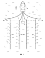
- FIG. 1 shows an example of seismic data acquisition for use with a migration method according to the invention.
- FIG. 2 shows a definition of polar angle and azimuth angle of symmetry axis as used in the present invention.
- FIG. 3 shows a graphic example of an exact solution to the dispersion relationship in a three dimensional TTI medium.
- FIGS. 4A through 4D show graphs comparing an exact solution to the dispersion relationship for TTI media to second order and fourth order Fourier finite difference approximations according to the invention.
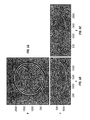
- FIGS. 5A, 5B and 5C show calculated impulse responses.
- FIG. 6 shows a flow chart of an example implementation of a migration method.
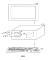
- FIG. 7 shows a programmable general-purpose computer with readable storage media and a display.
- FIG. 1 shows an example of a marine seismic survey system in which a plurality of streamer cables 30 are towed behind a seismic survey vessel 32 moving on the surface of a body of water 11 such as a lake or the ocean.
- One or more seismic energy sources 34 also typically towed behind the seismic vessel 32, or by another vessel.
- the seismic source 34 which typically is an air gun or array of air guns, but may also be a water gun or other type of seismic source known in the art, is actuated at selected times so as to impart seismic energy into the formations below the bottom of the water 11.
- the seismic energy is reflected by reflectors in the subsurface (below the water bottom) and is eventually detected by seismic sensors 3 disposed at longitudinally spaced apart positions in the streamers 30.
- a record of signals detected by each of the sensors 3 is made, indexed with respect to the actuation time of the seismic source 34.
- Such recording may be made by a suitable recording device (not shown) on the seismic survey vessel 32.
- Paravanes 35 are used to maintain the streamer cables 30 in the desired lateral position with respect to the centerline of the vessel 32.
- the invention may also be implemented, however, using seismic cables that are maintained at a substantially stationary position in a body of water, either floating at a selected depth or lying on the bottom of the body of water, in which case the seismic source 34 may be towed behind a different vessel to generate seismic energy pulses at varying locations.
- the seismic energy source 34 may also be maintained in a fixed position.
- the example arrangement shown in FIG. 1 including four streamer cables 30, paravanes 35 and the source 34 all towed by the same vessel 32 is not a limit on the scope of the present invention.
- the marine acquisition system example shown in FIG. 1 is not a limitation on the use of seismic data acquired using marine systems. It is within the scope of the present invention to acquire seismic data on the land surface for use with a migration method according to the invention.
- Depth migration is a process performed on seismic data in which depth estimates to one or more reflective horizons (acoustic impedance boundaries) in the subsurface are made from the travel time of seismic energy from the source 34, to the reflective horizons, and back to the seismic sensors 3.
- "Phase shift" migration uses a three dimensional dispersion relation of the scalar wave equation in order to perform seismic wavefield downward extrapolation.
- the presently described migration method is an example of phase shift migration.
- TTI tilted transversely isotropic
- s x k x ⁇ p 0 / ⁇
- ⁇ p 0 represents compressional velocity in the symmetry axis direction (P wave) and ⁇ represents the angular frequency.
- ⁇ , and ⁇ are the Thomsen anisotropic parameters
- ⁇ is the polar angle (angle of inclination of the symmetry axis with respect to a selected reference)
- ⁇ is the azimuth angle of the transverse isotropic symmetry axis.
- the polar and azimuth angles are shown in FIG. 2 as to how they relate to the coordinate system of seismic imaging.
- the coordinate system includes the x axis as horizontal and along the direction of the streamer cables (30 in FIG. 1 ), they axis as horizontal and transverse to the streamer cables, and the z axis as vertical.
- the Thomsen anisotropic parameters are explained, for example, in U.S. Patent No.
- the fourth order polynomial expression in equation (1) has four solutions, each solution corresponding to one of upgoing compressional (P) waves, downgoing P waves, upgoing shear (S) waves, and downgoing S waves, respectively.
- the S waves are not part of the method because zero S-wave velocity is assumed for purposes of the present migration technique.
- the medium velocity v p0 is the velocity along the direction of the axis of symmetry of a TTI medium.
- the accuracy of the FFD approximation at high angles of propagation depends on the selected order (3 n ) in equation (3), the value of the coefficients a i , b i , c i and d i , and the combination of the parameters ⁇ , ⁇ , ⁇ , and ⁇ . Equation (3) was derived under the assumption that the reference medium is isotropic. This assumption is not required for our method, however it simplifies the implementation of the table-based TTI FFD migration.
- equation (1) To create the table, for selected values of m, ⁇ , ⁇ , ⁇ , and ⁇ within the known ranges of the foregoing parameters, an exact solution to equation (1) is evaluated to numerically compute the corresponding dispersion relation function.
- the coefficients a i , b i , c i and d i that produce a best fit of equation (3) to the numerical dispersion relation are estimated, for example, by using a non-linear least-squares algorithm.
- the selected values of the parameters m , ⁇ , ⁇ , ⁇ , and ⁇ used to generate the table of numerical data can be increments within the known range of values of each of the foregoing parameters, for example, increments of 0.005, 0.01 or 0.02 of the full range of values for each such parameter.
- the dispersion relation is asymmetric not only with respect to the polar angle but also with respect to the azimuth angle. Because of the asymmetry, different optimized coefficients a i , b i , c i and d i may be necessary depending on the direction of propagation. In order to reduce numerical anisotropy when using a two-way splitting algorithm, a multy-way splitting approach can be employed. Thus the coefficients a i , b i , c i and d i are tabulated for each splitting direction. See, for example, Ristow, D., and T. Ruhl, "3-D implicit finite-difference migration by multiway splitting", Geophysics, 62, 554 (1997 ).
- FIGS. 4A through 4D show the fit of the approximate (obtained by non-linear least-squares) to the exact dispersion relations in FIG. 3 for splitting directions 0, 45 degrees, 90 degrees, and 135 degrees, respectively.
- the exact dispersion relation is shown by curves labeled 40 (and indicated by open circles).
- curves for the exact solution second order approximation and fourth order approximation are identified as explained above, and these are the same for each of FIGS. 4A through 4D . Note that in many locations, curves 40, 44 and 42 are superimposed.
- FIG. 5A shows an impulse response calculated for a collocated seismic source and a seismic receiver disposed in the center of the crossed axes.
- the impulse response of a migration program is its output when the input data is a unit impulse (or a band-limited impulse).
- As a linear process migration is completely characterized by its impulse response. The latter describes a definite relationship between input data and output. That is, for any input data, the output image can be calculated in terms of the input and the impulse response.
- the impulse response test is generally used to diagnose how accurately the migration program would image the subsurface formations.
- the impulse response is displayed in the horizontal plane ( x, y coordinate axes).
- FIG. 5B shows the same calculated impulse response displayed in the x, z plane.
- This plane represents the "in-line” direction, which is generally along the length of the seismic sensor streamers (30 in FIG. 1 ).
- the plot in FIG. 5C is in the so-called "cross-line” direction, or transverse to the direction of the streamers (30 in FIG. 1 ).
- Seismic data are acquired at 60, for example, using a system such as shown in FIG. 1 .
- the seismic data are recorded in the time domain and are represented by sensor or receiver positions that may be defined in a coordinate plane with respect to a selected reference, for example, the UTM coordinates system.
- the receiver wavefield is transformed at 64 into the frequency domain, for example, by using a fast Fourier transform.
- an inverse Fourier transform is applied to the propagated receiver wavefield from the wavenumber domain to the spatial domain ( x and y ).
- the thin lens term of equation (3) is applied to the phase shifted receiver wavefield.
- the thin lens term is s z0 - m from equation (3).
- the finite difference term (the summation) from equation (3) is applied to the thin lens result.
- a seismic wavefield is initiated from a synthetic seismic energy source disposed at the surface at a source position denominated ( x, y, 0).
- the source wavefield is transformed at 66 to the frequency domain, for example, by using a fast Fourier transform.
- an inverse Fourier transform is applied to the propagated, transformed source wavefield from the wavenumber domain to the spatial domain ( x and y ).
- a thin lens term is applied to the phase shifted source wavefield.
- the thin lens term is the quantity ( s z0 - m ) from equation (3).
- the finite difference term (the summation) from equation (3) is applied to the thin lens result.
- the images generated by the foregoing procedure may be stored in a computer readable device or displayed for further processing and/or interpretation.
- a method for migrating seismic data according to the invention may be implemented on a programmable computer.
- the foregoing migration method as explained above can be embodied in computer-readable code stored on a computer readable medium, such as floppy disk 51 or a CD-ROM 53 loaded into respective reading or read/write devices 58, 56, or a magnetic hard drive 59 forming part of a general purpose programmable computer.
- the computer includes a central processing unit 50, a user input device such as a keyboard 54 and a user display 52 such as a flat panel LCD display or cathode ray tube display.
- the computer readable medium includes logic operable to cause the computer to execute acts as set forth above and explained with reference to FIG. 6 .
- a method according to the invention may provide a procedure to implement seismic migration in TTI media that is less computationally expensive than methods known in the art.
Landscapes
- Engineering & Computer Science (AREA)
- Remote Sensing (AREA)
- Physics & Mathematics (AREA)
- Life Sciences & Earth Sciences (AREA)
- Acoustics & Sound (AREA)
- Environmental & Geological Engineering (AREA)
- Geology (AREA)
- General Life Sciences & Earth Sciences (AREA)
- General Physics & Mathematics (AREA)
- Geophysics (AREA)
- Geophysics And Detection Of Objects (AREA)
Abstract
Description
- The invention relates generally to the field of seismic data migration processing. More particularly, the invention relates to methods for migrating seismic data that can accurately approximate energy propagation in transversely isotropic media wherein the axis of symmetry is inclined with respect to a measurement surface that holds an array of seismic sensors.
- Seismic surveying is used to evaluate structures of, compositions of, and fluid content of subsurface earth formations. A particular application for seismic surveying is to infer the presence of useful materials, such as petroleum, in the subsurface earth formations. Generally, seismic surveying includes deploying an array of seismic sensors at or near the earth's surface, and deploying a seismic energy source near the sensors also at or near the surface. The seismic energy source is actuated and seismic energy emanates from the source, traveling generally downwardly through the subsurface until it reaches one or more acoustic impedance boundaries. Seismic energy is reflected from the one or more impedance boundaries, where it then travels upwardly until being detected by one or more of the sensors. Structure and composition of the subsurface is inferred from the travel time of the seismic energy, and the amplitude and phase of the various frequency components of the seismic energy with respect to the energy emanating from the seismic source.
- In order to infer the structures of subsurface earth formations from seismic travel times measured at the earth's surface from a source position at the surface, it is necessary to determine the velocity of the various formations through which the seismic energy passes. Velocities of the earth formations can vary both with respect to depth in the earth (vertically), and with respect to geographic position (laterally). Seismic data, however, are recorded only with respect to time. Methods known in the art for estimating velocities of the earth formations, both vertically and laterally, rely on inferences about the travel path geometry of the seismic energy as it travels from the seismic source to the various seismic receivers deployed at the earth's surface.
- Migration is a process performed on seismic data in which depth estimates to one or more reflective horizons (acoustic impedance boundaries) in the earth are made from the "two way" travel time of seismic energy from the source, to the reflective horizons, and back to the seismic receivers. The depth estimates are computed and displayed with respect to geographic position of the reflective horizons. Depth estimates based on two way travel time must be corrected for the effects of seismic energy travel path differences between various seismic energy source and receiver geographic positions that are used during data acquisition. In order to correct the depth estimates for source and receiver positions, it is necessary to accurately account for the velocity of seismic energy in the earth from the earth's surface to (or the ocean bottom in marine seismic data) to each subsurface reflective horizon.
- It is known in the art that some earth formations are anisotropic with respect to seismic velocity. Anisotropy can be observed as different velocity in a single medium depending on the direction of propagation of the seismic energy through the medium. In anisotropic earth formations, the depth estimating (imaging) process needs to take the anisotropy into account in order to accurately position the seismic reflective horizons with respect to depth and geographic position. In transversely isotropic media, many of which are structurally laminated, seismic waves can propagate at higher velocity in the direction of the formation layer planes (laminations) than perpendicular to the laminations. If the laminations are oriented substantially horizontally, vertical transverse isotropic ("VTI") migration techniques can be used. If the formation layers are inclined ("dipping") with respect to the Earth's surface, as in subsurface structures including anticlines and thrust belts, however, a tilted transversely isotropic ("TTI") migration technique is more appropriate. See, for example, Lawton, D. C., Isaac, J. H., Vestrum, R. W., and Leslie, J. M., (2001), "Slip-slidin' away-some practical implications of seismic velocity anisotropy on depth imaging", The Leading Edge, 1, pp. 70-73. See also, Yan, L., Lines, L. R., and Lawton, D. C., (2004), "Influence of seismic anisotropy on prestack depth migration", The Leading Edge, 1, pp. 30-36
- TTI migration has typically been performed using Kirchhoff methods, because the complexity of the subsurface formations can be handled by using anisotropic ray tracing in travel-time table calculation. More recently, two-way wave equation methods (reverse time migration or "RTM") have been developed. See, for example, Du, X., Bancroft, J. C., and Lines, L R., (2005), "Reverse-time migration for tilted TI media", SEG Expanded Abstracts 24, 1930 and Du, X., Bancroft, J. C., Lawton D. C., and Lines, L. R., (2006), "Evaluations of prestack anisotropic Kirchhoff, phase-shift-plus-interpolation and reverse-time depth migration methods for dipping TI media", SEG Expanded Abstracts 25, 179. However, two-way wave equation methods such that those described in the foregoing publications have proven too computationally expensive to be widely used commercially.
In methods for seismic migration known as "explicit finite-difference" and phase-shift plus interpolation ("PSPI"), the complexity of the algorithms do not significantly increase when operating on a TTI medium (Ferguson and Margrave, 1998). However, in practice, their computational cost increases because in a three dimensional TTI medium the first requires two dimensional convolution with relatively large convolution filters, and the second requires extrapolating many reference wavefields, even if simplifying assumptions about the medium are made. See, Bale, R. A., Gray S. H., and Graziella M., "TTI wave-equation migration ", SEG Expanded Abstracts 26, 2295 (2007).
A more computationally economical alternative is an "implicit finite-difference" method. See, Claerbout, J., 1985, "Imaging the earth interior", Blackwell Scientific Publications (1985). The Clarebout method has been used to approximate the TTI dispersion relation. See, Shan, G., "Optimized implicit finite-difference migration for TTI media", SEG Expanded Abstracts 26, 2290 (2007). The approximation described in the Shan publication consists of a combination of odd and even rational function series. Finite-differences coefficients for the rational function series can be estimated by least-squares optimization. Implementations of TTI migration using techniques such as described in the Shan publication do not significantly increase the computational cost as contrasted with migration in isotropic or VTI media. The foregoing observation led to the conclusion that it is possible to implement a Fourier finite difference migration technique that is not excessively computationally expensive. - A method for migrating three dimensional seismic data in tilted transversely isotropic media ("TTI") includes generating numerical solutions to an exact relationship for a three dimensional dispersion relationship of seismic energy traveling through TTI media. The numerical solutions include selected input values of polar angle and azimuth angle of a transverse isotropic axis of symmetry and selected values of Thomsen anisotropic parameters, the exact relationship defining wavenumbers for seismic data in three dimensions. Coefficients of a two dimensional Fourier finite difference relationship are determined in different splitting directions that result in a best fit to the exact solution of the three dimensional dispersion relationship. Seismic data are migrated using the determined coefficients by using a Fourier finite difference migration scheme.
- A computer program according to another aspect of the invention is stored in a computer readable medium. The program includes logic operable to cause a programmable computer to perform steps including the following. Numerical solutions are generated for an exact relationship for a three dimensional dispersion relationship of seismic energy traveling through TTI media. The numerical solutions include selected input values of polar angle and azimuth angle of a transverse isotropic axis of symmetry and selected values of Thomsen anisotropic parameters, the exact relationship defining wavenumbers for seismic data in three dimensions. Coefficients of a two dimensional Fourier finite difference relationship are determined in different directions that result in a best fit to the exact solution of the three dimensional dispersion relationship. Seismic data are migrated using the determined coefficients in Fourier finite difference migration scheme.
- Other aspects and advantages of the invention will be apparent from the following description and the appended claims.
-
FIG. 1 shows an example of seismic data acquisition for use with a migration method according to the invention. -
FIG. 2 shows a definition of polar angle and azimuth angle of symmetry axis as used in the present invention. -
FIG. 3 shows a graphic example of an exact solution to the dispersion relationship in a three dimensional TTI medium. -
FIGS. 4A through 4D show graphs comparing an exact solution to the dispersion relationship for TTI media to second order and fourth order Fourier finite difference approximations according to the invention. -
FIGS. 5A, 5B and 5C show calculated impulse responses. -
FIG. 6 shows a flow chart of an example implementation of a migration method. -
FIG. 7 shows a programmable general-purpose computer with readable storage media and a display. -
FIG. 1 shows an example of a marine seismic survey system in which a plurality ofstreamer cables 30 are towed behind aseismic survey vessel 32 moving on the surface of a body ofwater 11 such as a lake or the ocean. One or moreseismic energy sources 34 also typically towed behind theseismic vessel 32, or by another vessel. Theseismic source 34, which typically is an air gun or array of air guns, but may also be a water gun or other type of seismic source known in the art, is actuated at selected times so as to impart seismic energy into the formations below the bottom of thewater 11. The seismic energy is reflected by reflectors in the subsurface (below the water bottom) and is eventually detected byseismic sensors 3 disposed at longitudinally spaced apart positions in thestreamers 30. Typically a record of signals detected by each of thesensors 3 is made, indexed with respect to the actuation time of theseismic source 34. Such recording may be made by a suitable recording device (not shown) on theseismic survey vessel 32. -
Paravanes 35 are used to maintain thestreamer cables 30 in the desired lateral position with respect to the centerline of thevessel 32. The invention may also be implemented, however, using seismic cables that are maintained at a substantially stationary position in a body of water, either floating at a selected depth or lying on the bottom of the body of water, in which case theseismic source 34 may be towed behind a different vessel to generate seismic energy pulses at varying locations. Theseismic energy source 34 may also be maintained in a fixed position. Further, the example arrangement shown inFIG. 1 including fourstreamer cables 30,paravanes 35 and thesource 34 all towed by thesame vessel 32 is not a limit on the scope of the present invention. It is also to be clearly understood that the marine acquisition system example shown inFIG. 1 is not a limitation on the use of seismic data acquired using marine systems. It is within the scope of the present invention to acquire seismic data on the land surface for use with a migration method according to the invention. - Depth migration, as explained in the Background section herein, is a process performed on seismic data in which depth estimates to one or more reflective horizons (acoustic impedance boundaries) in the subsurface are made from the travel time of seismic energy from the
source 34, to the reflective horizons, and back to theseismic sensors 3. "Phase shift" migration uses a three dimensional dispersion relation of the scalar wave equation in order to perform seismic wavefield downward extrapolation. The presently described migration method is an example of phase shift migration. - The three dimensional dispersion relation for a tilted transversely isotropic ("TTI") medium, assuming zero shear wave velocity (as explained in Alkhalifah, T., "Acoustic approximations for processing in transversely isotropic media" Geophysics, 63, 623-631 (1998)), can be represented by a fourth order polynomial equation. One such equation is described in Shan, G., and Biondi, B. L., 3D "Wavefield extrapolation in laterally-varying tilted TI media", 75th Annual International Meeting, SEG, Expanded Abstracts, 104-107 (2005) and is show below:

- In the foregoing equation, sz = kzν p0/
ω is the normalized vertical (z) wave number, sx = kxν p0/ω and s y = kyν p0/ω are the normalized horizontal (x, y) wave numbers, where k represents wavenumber in the respective domain ν p0 represents compressional velocity in the symmetry axis direction (P wave) andω represents the angular frequency. The polynomial coefficients a1 through a4 can be determined by the following expressions:
- In the above expressions for determining the polynomial coefficients, ε, and δ are the Thomsen anisotropic parameters, θ is the polar angle (angle of inclination of the symmetry axis with respect to a selected reference), and ψ is the azimuth angle of the transverse isotropic symmetry axis. The polar and azimuth angles are shown in
FIG. 2 as to how they relate to the coordinate system of seismic imaging. Generally, the coordinate system includes the x axis as horizontal and along the direction of the streamer cables (30 inFIG. 1 ), they axis as horizontal and transverse to the streamer cables, and the z axis as vertical. The Thomsen anisotropic parameters are explained, for example, inU.S. Patent No. 6,785,612 issued to Zhang and assigned to the assignee of the present invention. See also, Thomsen, L., "Weak elastic anisotropy", Geophysics, Oct. 1986, pp. 1954-1966, vol. 51, No. 10 (1986) for an explanation of the Thomsen parameters. - The fourth order polynomial expression in equation (1) has four solutions, each solution corresponding to one of upgoing compressional (P) waves, downgoing P waves, upgoing shear (S) waves, and downgoing S waves, respectively. The S waves are not part of the method because zero S-wave velocity is assumed for purposes of the present migration technique. In a practical implementation of a method according to the invention, only the root for downward propagating P waves is solved.
FIG. 3 shows a graph of a solution to equation (1) corresponding to a downgoing P wave, and values of ε = 0.4, δ = 0.2, θ = 60 degrees, and ψ = 50 degrees. - Based on a two dimensional implicit finite-difference approximation for the TTI dispersion relation described in, Shan, G., "Optimized implicit finite-difference migration for TTI media", SEG Expanded Abstracts 26, 2290 (2007), a three dimensional Fourier finite-difference ("FFD") migration for TTI media has been developed that consists of three terms: a phase shift term, a thin lens term, and a finite-difference term. The TTI approximation of the present invention uses a combination of odd and even rational function series of selected order n. The TTI dispersion relation approximation, reduced to a 2D relation along any splitting axis, can be expressed as:

- The ratio m between the inhomogeneous medium velocity, and a reference medium velocity can be determined by the expression:

- The medium velocity vp0 is the velocity along the direction of the axis of symmetry of a TTI medium. The accuracy of the FFD approximation at high angles of propagation (high angle with reference to the axis of symmetry) depends on the selected order (3n) in equation (3), the value of the coefficients ai, bi, ci and di , and the combination of the parameters ε, δ, θ, and ψ. Equation (3) was derived under the assumption that the reference medium is isotropic. This assumption is not required for our method, however it simplifies the implementation of the table-based TTI FFD migration.
- To create the table, for selected values of m, ε, δ, θ, and ψ within the known ranges of the foregoing parameters, an exact solution to equation (1) is evaluated to numerically compute the corresponding dispersion relation function. The coefficients ai, bi, ci and di that produce a best fit of equation (3) to the numerical dispersion relation are estimated, for example, by using a non-linear least-squares algorithm. The term sz0 can be computed analytically, by evaluating equation (1) at sx = 0, sy = 0. The selected values of the parameters m, ε, δ, θ, and ψ used to generate the table of numerical data can be increments within the known range of values of each of the foregoing parameters, for example, increments of 0.005, 0.01 or 0.02 of the full range of values for each such parameter.
- In a three dimensional medium, as shown by the graph in
FIG. 3 , the dispersion relation is asymmetric not only with respect to the polar angle but also with respect to the azimuth angle. Because of the asymmetry, different optimized coefficients ai, bi, ci and di may be necessary depending on the direction of propagation. In order to reduce numerical anisotropy when using a two-way splitting algorithm, a multy-way splitting approach can be employed. Thus the coefficients ai, bi, ci and di are tabulated for each splitting direction. See, for example, Ristow, D., and T. Ruhl, "3-D implicit finite-difference migration by multiway splitting", Geophysics, 62, 554 (1997). -
FIGS. 4A through 4D show the fit of the approximate (obtained by non-linear least-squares) to the exact dispersion relations inFIG. 3 for splittingdirections 0, 45 degrees, 90 degrees, and 135 degrees, respectively. The exact dispersion relation is shown by curves labeled 40 (and indicated by open circles). A second order approximation using equation (3), (after substituting for n=1 and d1 =0), is shown by curves labeled 44 (and indicated by open squares). A fourth order approximation (n=2; d1 =d2 =0) is shown by curves labeled 42 (and indicated by solid triangles). The fourth order approximation provides less error than the second order approximation. InFIG. 4D curves for the exact solution, second order approximation and fourth order approximation are identified as explained above, and these are the same for each ofFIGS. 4A through 4D . Note that in many locations, curves 40, 44 and 42 are superimposed. -
FIG. 5A shows an impulse response calculated for a collocated seismic source and a seismic receiver disposed in the center of the crossed axes. The impulse response of a migration program is its output when the input data is a unit impulse (or a band-limited impulse). As a linear process, migration is completely characterized by its impulse response. The latter describes a definite relationship between input data and output. That is, for any input data, the output image can be calculated in terms of the input and the impulse response. The impulse response test is generally used to diagnose how accurately the migration program would image the subsurface formations. The impulse response is displayed in the horizontal plane (x, y coordinate axes).FIG. 5B shows the same calculated impulse response displayed in the x, z plane. This plane represents the "in-line" direction, which is generally along the length of the seismic sensor streamers (30 inFIG. 1 ). InFIG. 5B , the source position is at z = 0 and x = 1250 (along the vertical axis position).FIG. 5C shows the same impulse response displayed in the y, z plane, with the source position at z = 0 and along the vertical axis position (y = 1250). The plot inFIG. 5C is in the so-called "cross-line" direction, or transverse to the direction of the streamers (30 inFIG. 1 ). - An example implementation of a migration method will be explained with reference to a flow chart in
FIG. 6 . Seismic data are acquired at 60, for example, using a system such as shown inFIG. 1 . The seismic data are recorded in the time domain and are represented by sensor or receiver positions that may be defined in a coordinate plane with respect to a selected reference, for example, the UTM coordinates system. The data in the time domain may be represented, for each receiver, by R(x, y, z=0, t), and referred to as the receiver wavefield at the surface. The receiver wavefield is transformed at 64 into the frequency domain, for example, by using a fast Fourier transform. The transformed receiver wavefield may be represented by R(x, y, z=0, ω). The transformed receiver wavefield is further transformed at 68, such as by fast Fourier transform, to the wavenumber domain to produce R(kx, ky, z = 0, ω). At 72, the phase shift term (the first part of equation (3) within the square root) is applied to the receiver wavefield in the wavenumber domain to propagate it to a first depth increment from the surface (z = 1). The result may be represented by R(kx,ky, z = 1, ω). At 76 an inverse Fourier transform is applied to the propagated receiver wavefield from the wavenumber domain to the spatial domain (x and y). At 80, the thin lens term of equation (3) is applied to the phase shifted receiver wavefield. The thin lens term is sz0 - m from equation (3). At 84, the finite difference term (the summation) from equation (3) is applied to the thin lens result. - At 62, a seismic wavefield is initiated from a synthetic seismic energy source disposed at the surface at a source position denominated (x, y, 0). The source signature or wavefield may be, for example, a bandpass filtered impulse (amplitude spike at time = 0) or other synthetic source wavelet known in the art used for wave equation migration. The source wavefield is generated in the time domain and may be represented in the time domain by S(x, y, z=0, t). The source wavefield is transformed at 66 to the frequency domain, for example, by using a fast Fourier transform. The transformed source wavefield may be represented by S(x, y, z=0, ω). The transformed source wavefield is further transformed at 70, such as by fast Fourier transform, to the wavenumber domain to produce a wavefield represented by S(kx , ky, z = 0, ω). At 74, a phase shift is performed on the wavenumber domain transformed source wavefield to propagate it to a first depth increment from the surface represented by (z = 1). This phase shift has an opposite sign to the one applied to the receiver wavefield. The result of the propagation may be represented by S(kx,ky, z = 1, ω). At 78 an inverse Fourier transform is applied to the propagated, transformed source wavefield from the wavenumber domain to the spatial domain (x and y). At 82, a thin lens term is applied to the phase shifted source wavefield. The thin lens term is the quantity (sz0 - m) from equation (3). At 86, the finite difference term (the summation) from equation (3) is applied to the thin lens result.
- The complex conjugate of the source wavefield, propagated to the depth increment z = 1 (from 86), is then cross-correlated, at 88, with the propagated receiver wavefield also at the depth increment z = 1 (from 84) to obtain an image value at that depth. At 90 the image at depth level z=1 can be saved in memory, or written to a local or external computer storage device. The foregoing procedures are repeated in their entirety, at 92, until a selected depth within the subsurface is reached, that is, z = n, where n represents the maximum depth desired for the image divided by the number of depth increments per unit of depth. The images generated by the foregoing procedure may be stored in a computer readable device or displayed for further processing and/or interpretation.
- A method for migrating seismic data according to the invention may be implemented on a programmable computer. Referring to
FIG. 7 , the foregoing migration method as explained above can be embodied in computer-readable code stored on a computer readable medium, such asfloppy disk 51 or a CD-ROM 53 loaded into respective reading or read/writedevices hard drive 59 forming part of a general purpose programmable computer. The computer, as known in the art, includes acentral processing unit 50, a user input device such as akeyboard 54 and auser display 52 such as a flat panel LCD display or cathode ray tube display. According to this aspect of the invention, the computer readable medium includes logic operable to cause the computer to execute acts as set forth above and explained with reference toFIG. 6 . - A method according to the invention may provide a procedure to implement seismic migration in TTI media that is less computationally expensive than methods known in the art.
- While the invention has been described with respect to a limited number of embodiments, those skilled in the art, having benefit of this disclosure, will appreciate that other embodiments can be devised which do not depart from the scope of the invention as disclosed herein. Accordingly, the scope of the invention should be limited only by the attached claims.
Claims (8)
- A method for migrating three dimensional seismic data in tilted transversely isotropic ("TTI") media, the seismic data representing signals acquired by deploying seismic sensors and a seismic energy source, actuating the source and detecting seismic energy in response thereto, the method comprising:transforming the seismic data into the wavenumber-frequency domain;generating numerical solutions to an exact relationship for a three dimensional dispersion relationship of seismic energy traveling through TTI media, the numerical solutions including selected input values of polar angle and azimuth angle of a transverse isotropic axis of symmetry and selected values of Thomsen anisotropic parameters, the exact relationship defining wavenumbers for seismic data in three dimensions;determining coefficients of a two dimensional Fourier finite difference relationship that result in a best fit of wavenumbers to the numerical solutions for each splitting direction;migrating the transformed seismic data using the wavenumbers from the Fourier finite difference relationship to generate an image; andat least one of storing and displaying the image.
- The method of claim 1 wherein the Fourier finite difference relationship includes a phase shift term, a thin lens term and a finite difference term.
- The method of claim 1 wherein the determining coefficients comprises multiple-way splitting.
- The method of claim 1 wherein the determining coefficients comprises non-linear least squared fitting.
- A computer program stored in a computer readable medium, the program containing logic operable to cause a programmable computer to perform steps comprising:transforming three dimensional seismic data into the wavenumber-frequency domain, the seismic data representing signals acquired by deploying seismic sensors and a seismic energy source, actuating the source and detecting seismic energy in response thereto;generating numerical solutions to an exact relationship for a three dimensional dispersion relationship of seismic energy traveling through tilted transversely isotropic media, the numerical solutions including selected input values of polar angle and azimuth angle of a transverse isotropic axis of symmetry and selected values of Thomsen anisotropic parameters, the exact relationship defining wavenumbers for seismic data in three dimensions;determining coefficients of a two dimensional Fourier finite difference relationship that result in a best fit of wavenumbers to the numerical solutions for each splitting direction;migrating the transformed seismic data using the wavenumbers from the Fourier finite difference relationship to generate an image; andat least one of storing and displaying the image.
- The computer program of claim 5 wherein the Fourier finite difference relationship includes a phase shift term, a thin lens term and a finite difference term.
- The computer program of claim 5 wherein the determining coefficients comprises multiple-way splitting.
- The computer program of claim 5 wherein the determining coefficients comprises non-linear least squared fitting.
Applications Claiming Priority (2)
| Application Number | Priority Date | Filing Date | Title |
|---|---|---|---|
| US12/198,516 US8296620B2 (en) | 2008-08-26 | 2008-08-26 | Data devices including multiple error correction codes and methods of utilizing |
| US12/383,622 US9864082B2 (en) | 2008-11-06 | 2009-03-27 | Fourier finite-difference migration for three dimensional tilted transverse isotropic media |
Publications (2)
| Publication Number | Publication Date |
|---|---|
| EP2184620A1 true EP2184620A1 (en) | 2010-05-12 |
| EP2184620B1 EP2184620B1 (en) | 2011-10-26 |
Family
ID=41698021
Family Applications (1)
| Application Number | Title | Priority Date | Filing Date |
|---|---|---|---|
| EP20090174924 Active EP2184620B1 (en) | 2008-08-26 | 2009-11-03 | Fourier finite-difference migration for three dimensional tilted transverse isotropic media |
Country Status (1)
| Country | Link |
|---|---|
| EP (1) | EP2184620B1 (en) |
Cited By (4)
| Publication number | Priority date | Publication date | Assignee | Title |
|---|---|---|---|---|
| EP2885656A4 (en) * | 2012-08-17 | 2016-04-06 | Landmark Graphics Corp | Systems and methods for imaging seismic data |
| CN112067698A (en) * | 2020-09-14 | 2020-12-11 | 南昌航空大学 | A Time-Frequency Combined Fast All-Focus Ultrasound Imaging Method |
| CN112285772A (en) * | 2020-10-07 | 2021-01-29 | 长安大学 | Finite difference numerical simulation method, finite difference numerical simulation system, finite difference numerical simulation medium, computer equipment and application |
| US12351775B2 (en) | 2021-05-14 | 2025-07-08 | Ecolab Usa Inc. | Neutralizing instrument reprocessing |
Citations (1)
| Publication number | Priority date | Publication date | Assignee | Title |
|---|---|---|---|---|
| US6785612B1 (en) | 2003-05-29 | 2004-08-31 | Pgs Americas, Inc. | Seismic velocity update for anisotropic depth migration |
-
2009
- 2009-11-03 EP EP20090174924 patent/EP2184620B1/en active Active
Patent Citations (1)
| Publication number | Priority date | Publication date | Assignee | Title |
|---|---|---|---|---|
| US6785612B1 (en) | 2003-05-29 | 2004-08-31 | Pgs Americas, Inc. | Seismic velocity update for anisotropic depth migration |
Non-Patent Citations (18)
| Title |
|---|
| ALKHALIFAH T.: "An acoustic wave equation for anisotropic media", GEOPHYSICS, SEG, vol. 65, no. 4, July 2000 (2000-07-01) - August 2000 (2000-08-01), pages 1239 - 1250, XP002570798 * |
| ALKHALIFAH, T.: "Acoustic approximations for processing in transversely isotropic media", GEOPHYSICS, vol. 63, 1998, pages 623 - 631 |
| BALE, R. A.; GRAY S. H.; GRAZIELLA M.: "TTI wave-equation migration", SEG EXPANDED ABSTRACTS, vol. 26, 2007, pages 2295 |
| CLAERBOUT, J.: "Imaging the earth interior", 1985, BLACKWELL SCIENTIFIC PUBLICATIONS |
| DU, X. ET AL.: "Evaluations of prestack anisotropic Kirchhoff, phase-shift- plus-interpolation and reverse-time depth migration methods for dipping TI media", SEG EXPANDED ABSTRACTS, vol. 25, 2006, pages 179 |
| DU, X.; BANCROFT, J. C.; LINES, L R.: "Reverse-time migration for tilted TI media", SEG EXPANDED ABSTRACTS 24, vol. 24, 2005 |
| KUMAR D., SEN M.K., FERGUSON R.J.: "Traveltime calculation and prestack migration in tilted transversely isotropic media", GEOPHYSICS, SEG, vol. 69, no. 1, January 2004 (2004-01-01) - February 2004 (2004-02-01), pages 37 - 44, XP002570796 * |
| LAWTON, D. C. ET AL.: "Slip-slidin' away-some practical implications of seismic velocity anisotropy on depth imaging", THE LEADING EDGE, vol. 1, 2001, pages 70 - 73 |
| RISTOW D., RÜHL T.: "3-D implicit finite-difference migration by multiway splitting", GEOPHYSICS, vol. 62, 1997, pages 554 - 567, XP002570793 * |
| RISTOW, D.; AND T. RUHL: "3-D implicit finite-difference migration by multiway splitting", GEOPHYSICS, vol. 62, 1997, pages 554 |
| SHAN G., BIONDI B.: "Plane -wave migration in tilted coordinates", GEOPHYSICS, SEG, vol. 73, no. 5, September 2008 (2008-09-01) - October 2008 (2008-10-01), pages S185 - S194, XP002570795 * |
| SHAN G.; BIONDI B. L.: "3D Wavefield extrapolation in laterally-varying tilted TI media", SEG, EXPANDED ABSTRACTS, 2005, pages 104 - 107, XP002570794 * |
| SHAN, G.: "Optimized implicit finite-difference migration for TTI media", SEG EXPANDED ABSTRACTS, vol. 26, 2007, pages 2290 |
| SHAN, G.: "Optimized implicit finite-difference migration for TTI media", SEG, EXPANDED ABSTRACTS, vol. 26, 2007, pages 2290 - 2294, XP002570792 * |
| SHAN, G.; BIONDI, B. L.: "Wavefield extrapolation in laterally-varying tilted TI media", 75TH ANNUAL INTERNATIONAL MEETING, SEG, EXPANDED ABSTRACTS, 2005, pages 104 - 107 |
| THOMSEN, L.: "Weak elastic anisotropy", GEOPHYSICS, vol. 51, no. 10, October 1986 (1986-10-01), pages 1954 - 1966 |
| YAN, L.; LINES, L. R.; LAWTON, D. C.: "Influence of seismic anisotropy on prestack depth migration", THE LEADING EDGE, vol. 1, 2004, pages 30 - 36 |
| ZHOU H., ZHANG G., BLOOR R.: "An anisotropic acoustic wave equation for modeling and migration in 2D TTI media", SEG, EXPANDED ABSTRACTS, 2006, pages 194 - 198, XP002570797 * |
Cited By (6)
| Publication number | Priority date | Publication date | Assignee | Title |
|---|---|---|---|---|
| EP2885656A4 (en) * | 2012-08-17 | 2016-04-06 | Landmark Graphics Corp | Systems and methods for imaging seismic data |
| US9536143B2 (en) | 2012-08-17 | 2017-01-03 | Landmark Graphics Corporation | Systems and methods for imaging seismic data |
| CN112067698A (en) * | 2020-09-14 | 2020-12-11 | 南昌航空大学 | A Time-Frequency Combined Fast All-Focus Ultrasound Imaging Method |
| CN112067698B (en) * | 2020-09-14 | 2023-08-04 | 南昌航空大学 | Time-frequency combined rapid full-focusing ultrasonic imaging method |
| CN112285772A (en) * | 2020-10-07 | 2021-01-29 | 长安大学 | Finite difference numerical simulation method, finite difference numerical simulation system, finite difference numerical simulation medium, computer equipment and application |
| US12351775B2 (en) | 2021-05-14 | 2025-07-08 | Ecolab Usa Inc. | Neutralizing instrument reprocessing |
Also Published As
| Publication number | Publication date |
|---|---|
| EP2184620B1 (en) | 2011-10-26 |
Similar Documents
| Publication | Publication Date | Title |
|---|---|---|
| US9864082B2 (en) | Fourier finite-difference migration for three dimensional tilted transverse isotropic media | |
| US10088588B2 (en) | Device and method for stable least-squares reverse time migration | |
| Veeken | Seismic stratigraphy, basin analysis and reservoir characterisation | |
| Schleicher et al. | 3-D true-amplitude finite-offset migration | |
| EP3227723B1 (en) | Seismic acquisition methods | |
| US9625593B2 (en) | Seismic data processing | |
| AU2013213704B2 (en) | Device and method for directional designature of seismic data | |
| US20120275267A1 (en) | Seismic Data Processing | |
| Willis et al. | A novel application of time-reversed acoustics: Salt-dome flank imaging using walkaway VSP surveys | |
| US7830747B2 (en) | Method for multi-azimuth prestack time migration for general heterogeneous, anisotropic media | |
| US7167414B2 (en) | Amplitude preserving prestack migration method | |
| US20150338536A1 (en) | P-wave and s-wave separation of seismic data in the presence of statics and irregular geometry | |
| US20120265445A1 (en) | Stable shot illumination compensation | |
| EP2184620B1 (en) | Fourier finite-difference migration for three dimensional tilted transverse isotropic media | |
| US20140297193A1 (en) | Seismic methods and systems employing shallow shear-wave splitting analysis using receiver functions | |
| Sollid et al. | Scattering-angle migration of ocean-bottom seismic data in weakly anisotropic media | |
| Gray et al. | Seismic, migration | |
| Landrø et al. | Using diving waves for detecting shallow overburden gas layers | |
| Tang et al. | Target-oriented wavefield tomography using synthesized Born data | |
| Pinson et al. | Seafloor sound-speed profile and interface dip angle characterization by the image source method | |
| Valenciano et al. | Fourier finite-difference migration for 3D TTI media | |
| Gerea et al. | Multicomponent true-amplitude anisotropic imaging | |
| Basi et al. | Topographic corrections to slowness measurements in parsimonious migration of land data | |
| Du | Prestack depth migration methods for isotopic and polar anisotropic media | |
| Kletenik-Edelman et al. | Local directional projection (LDP) specularity weights for enhancing and characterizing seismic reflectivity images |
Legal Events
| Date | Code | Title | Description |
|---|---|---|---|
| PUAI | Public reference made under article 153(3) epc to a published international application that has entered the european phase |
Free format text: ORIGINAL CODE: 0009012 |
|
| AK | Designated contracting states |
Kind code of ref document: A1 Designated state(s): AT BE BG CH CY CZ DE DK EE ES FI FR GB GR HR HU IE IS IT LI LT LU LV MC MK MT NL NO PL PT RO SE SI SK SM TR |
|
| AX | Request for extension of the european patent |
Extension state: AL BA RS |
|
| REG | Reference to a national code |
Ref country code: NO Ref legal event code: T1 |
|
| 17P | Request for examination filed |
Effective date: 20101103 |
|
| 17Q | First examination report despatched |
Effective date: 20101201 |
|
| GRAP | Despatch of communication of intention to grant a patent |
Free format text: ORIGINAL CODE: EPIDOSNIGR1 |
|
| RIC1 | Information provided on ipc code assigned before grant |
Ipc: G01V 1/28 20060101AFI20110421BHEP |
|
| GRAS | Grant fee paid |
Free format text: ORIGINAL CODE: EPIDOSNIGR3 |
|
| GRAA | (expected) grant |
Free format text: ORIGINAL CODE: 0009210 |
|
| AK | Designated contracting states |
Kind code of ref document: B1 Designated state(s): AT BE BG CH CY CZ DE DK EE ES FI FR GB GR HR HU IE IS IT LI LT LU LV MC MK MT NL NO PL PT RO SE SI SK SM TR |
|
| REG | Reference to a national code |
Ref country code: GB Ref legal event code: FG4D |
|
| REG | Reference to a national code |
Ref country code: CH Ref legal event code: EP |
|
| REG | Reference to a national code |
Ref country code: IE Ref legal event code: FG4D |
|
| REG | Reference to a national code |
Ref country code: DE Ref legal event code: R096 Ref document number: 602009003287 Country of ref document: DE Effective date: 20111229 |
|
| REG | Reference to a national code |
Ref country code: NL Ref legal event code: VDEP Effective date: 20111026 |
|
| REG | Reference to a national code |
Ref country code: NO Ref legal event code: T2 Effective date: 20111026 |
|
| LTIE | Lt: invalidation of european patent or patent extension |
Effective date: 20111026 |
|
| REG | Reference to a national code |
Ref country code: AT Ref legal event code: MK05 Ref document number: 530927 Country of ref document: AT Kind code of ref document: T Effective date: 20111026 |
|
| PG25 | Lapsed in a contracting state [announced via postgrant information from national office to epo] |
Ref country code: LT Free format text: LAPSE BECAUSE OF FAILURE TO SUBMIT A TRANSLATION OF THE DESCRIPTION OR TO PAY THE FEE WITHIN THE PRESCRIBED TIME-LIMIT Effective date: 20111026 Ref country code: BE Free format text: LAPSE BECAUSE OF FAILURE TO SUBMIT A TRANSLATION OF THE DESCRIPTION OR TO PAY THE FEE WITHIN THE PRESCRIBED TIME-LIMIT Effective date: 20111026 Ref country code: IS Free format text: LAPSE BECAUSE OF FAILURE TO SUBMIT A TRANSLATION OF THE DESCRIPTION OR TO PAY THE FEE WITHIN THE PRESCRIBED TIME-LIMIT Effective date: 20120226 |
|
| PG25 | Lapsed in a contracting state [announced via postgrant information from national office to epo] |
Ref country code: GR Free format text: LAPSE BECAUSE OF FAILURE TO SUBMIT A TRANSLATION OF THE DESCRIPTION OR TO PAY THE FEE WITHIN THE PRESCRIBED TIME-LIMIT Effective date: 20120127 Ref country code: PL Free format text: LAPSE BECAUSE OF FAILURE TO SUBMIT A TRANSLATION OF THE DESCRIPTION OR TO PAY THE FEE WITHIN THE PRESCRIBED TIME-LIMIT Effective date: 20111026 Ref country code: HR Free format text: LAPSE BECAUSE OF FAILURE TO SUBMIT A TRANSLATION OF THE DESCRIPTION OR TO PAY THE FEE WITHIN THE PRESCRIBED TIME-LIMIT Effective date: 20111026 Ref country code: SE Free format text: LAPSE BECAUSE OF FAILURE TO SUBMIT A TRANSLATION OF THE DESCRIPTION OR TO PAY THE FEE WITHIN THE PRESCRIBED TIME-LIMIT Effective date: 20111026 Ref country code: NL Free format text: LAPSE BECAUSE OF FAILURE TO SUBMIT A TRANSLATION OF THE DESCRIPTION OR TO PAY THE FEE WITHIN THE PRESCRIBED TIME-LIMIT Effective date: 20111026 Ref country code: SI Free format text: LAPSE BECAUSE OF FAILURE TO SUBMIT A TRANSLATION OF THE DESCRIPTION OR TO PAY THE FEE WITHIN THE PRESCRIBED TIME-LIMIT Effective date: 20111026 Ref country code: LV Free format text: LAPSE BECAUSE OF FAILURE TO SUBMIT A TRANSLATION OF THE DESCRIPTION OR TO PAY THE FEE WITHIN THE PRESCRIBED TIME-LIMIT Effective date: 20111026 Ref country code: PT Free format text: LAPSE BECAUSE OF FAILURE TO SUBMIT A TRANSLATION OF THE DESCRIPTION OR TO PAY THE FEE WITHIN THE PRESCRIBED TIME-LIMIT Effective date: 20120227 |
|
| PG25 | Lapsed in a contracting state [announced via postgrant information from national office to epo] |
Ref country code: MC Free format text: LAPSE BECAUSE OF NON-PAYMENT OF DUE FEES Effective date: 20111130 Ref country code: CY Free format text: LAPSE BECAUSE OF FAILURE TO SUBMIT A TRANSLATION OF THE DESCRIPTION OR TO PAY THE FEE WITHIN THE PRESCRIBED TIME-LIMIT Effective date: 20111026 |
|
| PG25 | Lapsed in a contracting state [announced via postgrant information from national office to epo] |
Ref country code: EE Free format text: LAPSE BECAUSE OF FAILURE TO SUBMIT A TRANSLATION OF THE DESCRIPTION OR TO PAY THE FEE WITHIN THE PRESCRIBED TIME-LIMIT Effective date: 20111026 Ref country code: DK Free format text: LAPSE BECAUSE OF FAILURE TO SUBMIT A TRANSLATION OF THE DESCRIPTION OR TO PAY THE FEE WITHIN THE PRESCRIBED TIME-LIMIT Effective date: 20111026 Ref country code: BG Free format text: LAPSE BECAUSE OF FAILURE TO SUBMIT A TRANSLATION OF THE DESCRIPTION OR TO PAY THE FEE WITHIN THE PRESCRIBED TIME-LIMIT Effective date: 20120126 Ref country code: SK Free format text: LAPSE BECAUSE OF FAILURE TO SUBMIT A TRANSLATION OF THE DESCRIPTION OR TO PAY THE FEE WITHIN THE PRESCRIBED TIME-LIMIT Effective date: 20111026 Ref country code: CZ Free format text: LAPSE BECAUSE OF FAILURE TO SUBMIT A TRANSLATION OF THE DESCRIPTION OR TO PAY THE FEE WITHIN THE PRESCRIBED TIME-LIMIT Effective date: 20111026 |
|
| REG | Reference to a national code |
Ref country code: IE Ref legal event code: MM4A |
|
| PG25 | Lapsed in a contracting state [announced via postgrant information from national office to epo] |
Ref country code: IT Free format text: LAPSE BECAUSE OF FAILURE TO SUBMIT A TRANSLATION OF THE DESCRIPTION OR TO PAY THE FEE WITHIN THE PRESCRIBED TIME-LIMIT Effective date: 20111026 Ref country code: RO Free format text: LAPSE BECAUSE OF FAILURE TO SUBMIT A TRANSLATION OF THE DESCRIPTION OR TO PAY THE FEE WITHIN THE PRESCRIBED TIME-LIMIT Effective date: 20111026 |
|
| PLBE | No opposition filed within time limit |
Free format text: ORIGINAL CODE: 0009261 |
|
| STAA | Information on the status of an ep patent application or granted ep patent |
Free format text: STATUS: NO OPPOSITION FILED WITHIN TIME LIMIT |
|
| REG | Reference to a national code |
Ref country code: FR Ref legal event code: ST Effective date: 20120817 |
|
| 26N | No opposition filed |
Effective date: 20120727 |
|
| PG25 | Lapsed in a contracting state [announced via postgrant information from national office to epo] |
Ref country code: IE Free format text: LAPSE BECAUSE OF NON-PAYMENT OF DUE FEES Effective date: 20111103 |
|
| REG | Reference to a national code |
Ref country code: DE Ref legal event code: R119 Ref document number: 602009003287 Country of ref document: DE Effective date: 20120601 |
|
| PG25 | Lapsed in a contracting state [announced via postgrant information from national office to epo] |
Ref country code: AT Free format text: LAPSE BECAUSE OF FAILURE TO SUBMIT A TRANSLATION OF THE DESCRIPTION OR TO PAY THE FEE WITHIN THE PRESCRIBED TIME-LIMIT Effective date: 20111026 |
|
| PG25 | Lapsed in a contracting state [announced via postgrant information from national office to epo] |
Ref country code: MK Free format text: LAPSE BECAUSE OF FAILURE TO SUBMIT A TRANSLATION OF THE DESCRIPTION OR TO PAY THE FEE WITHIN THE PRESCRIBED TIME-LIMIT Effective date: 20111026 Ref country code: MT Free format text: LAPSE BECAUSE OF FAILURE TO SUBMIT A TRANSLATION OF THE DESCRIPTION OR TO PAY THE FEE WITHIN THE PRESCRIBED TIME-LIMIT Effective date: 20111026 |
|
| PG25 | Lapsed in a contracting state [announced via postgrant information from national office to epo] |
Ref country code: FR Free format text: LAPSE BECAUSE OF NON-PAYMENT OF DUE FEES Effective date: 20111226 Ref country code: SM Free format text: LAPSE BECAUSE OF FAILURE TO SUBMIT A TRANSLATION OF THE DESCRIPTION OR TO PAY THE FEE WITHIN THE PRESCRIBED TIME-LIMIT Effective date: 20111026 Ref country code: ES Free format text: LAPSE BECAUSE OF FAILURE TO SUBMIT A TRANSLATION OF THE DESCRIPTION OR TO PAY THE FEE WITHIN THE PRESCRIBED TIME-LIMIT Effective date: 20120206 |
|
| PG25 | Lapsed in a contracting state [announced via postgrant information from national office to epo] |
Ref country code: LU Free format text: LAPSE BECAUSE OF NON-PAYMENT OF DUE FEES Effective date: 20111103 |
|
| PG25 | Lapsed in a contracting state [announced via postgrant information from national office to epo] |
Ref country code: DE Free format text: LAPSE BECAUSE OF NON-PAYMENT OF DUE FEES Effective date: 20120601 Ref country code: FI Free format text: LAPSE BECAUSE OF FAILURE TO SUBMIT A TRANSLATION OF THE DESCRIPTION OR TO PAY THE FEE WITHIN THE PRESCRIBED TIME-LIMIT Effective date: 20111026 |
|
| PG25 | Lapsed in a contracting state [announced via postgrant information from national office to epo] |
Ref country code: TR Free format text: LAPSE BECAUSE OF FAILURE TO SUBMIT A TRANSLATION OF THE DESCRIPTION OR TO PAY THE FEE WITHIN THE PRESCRIBED TIME-LIMIT Effective date: 20111026 |
|
| PG25 | Lapsed in a contracting state [announced via postgrant information from national office to epo] |
Ref country code: HU Free format text: LAPSE BECAUSE OF FAILURE TO SUBMIT A TRANSLATION OF THE DESCRIPTION OR TO PAY THE FEE WITHIN THE PRESCRIBED TIME-LIMIT Effective date: 20111026 |
|
| REG | Reference to a national code |
Ref country code: CH Ref legal event code: PL |
|
| PG25 | Lapsed in a contracting state [announced via postgrant information from national office to epo] |
Ref country code: CH Free format text: LAPSE BECAUSE OF NON-PAYMENT OF DUE FEES Effective date: 20131130 Ref country code: LI Free format text: LAPSE BECAUSE OF NON-PAYMENT OF DUE FEES Effective date: 20131130 |
|
| P01 | Opt-out of the competence of the unified patent court (upc) registered |
Effective date: 20230516 |
|
| PGFP | Annual fee paid to national office [announced via postgrant information from national office to epo] |
Ref country code: GB Payment date: 20250919 Year of fee payment: 17 |
|
| PGFP | Annual fee paid to national office [announced via postgrant information from national office to epo] |
Ref country code: NO Payment date: 20251020 Year of fee payment: 17 |