EP2184577A1 - Optical measurement apparatus, spectroscopic ellipsometer, recording medium, and measurement method - Google Patents
Optical measurement apparatus, spectroscopic ellipsometer, recording medium, and measurement method Download PDFInfo
- Publication number
- EP2184577A1 EP2184577A1 EP20090175052 EP09175052A EP2184577A1 EP 2184577 A1 EP2184577 A1 EP 2184577A1 EP 20090175052 EP20090175052 EP 20090175052 EP 09175052 A EP09175052 A EP 09175052A EP 2184577 A1 EP2184577 A1 EP 2184577A1
- Authority
- EP
- European Patent Office
- Prior art keywords
- main
- auxiliary
- measurement
- film
- film thickness
- Prior art date
- Legal status (The legal status is an assumption and is not a legal conclusion. Google has not performed a legal analysis and makes no representation as to the accuracy of the status listed.)
- Withdrawn
Links
Images


















Classifications
-
- G—PHYSICS
- G01—MEASURING; TESTING
- G01B—MEASURING LENGTH, THICKNESS OR SIMILAR LINEAR DIMENSIONS; MEASURING ANGLES; MEASURING AREAS; MEASURING IRREGULARITIES OF SURFACES OR CONTOURS
- G01B11/00—Measuring arrangements characterised by the use of optical techniques
- G01B11/02—Measuring arrangements characterised by the use of optical techniques for measuring length, width or thickness
- G01B11/06—Measuring arrangements characterised by the use of optical techniques for measuring length, width or thickness for measuring thickness ; e.g. of sheet material
- G01B11/0616—Measuring arrangements characterised by the use of optical techniques for measuring length, width or thickness for measuring thickness ; e.g. of sheet material of coating
- G01B11/0641—Measuring arrangements characterised by the use of optical techniques for measuring length, width or thickness for measuring thickness ; e.g. of sheet material of coating with measurement of polarization
- G01B11/065—Measuring arrangements characterised by the use of optical techniques for measuring length, width or thickness for measuring thickness ; e.g. of sheet material of coating with measurement of polarization using one or more discrete wavelengths
-
- G—PHYSICS
- G01—MEASURING; TESTING
- G01B—MEASURING LENGTH, THICKNESS OR SIMILAR LINEAR DIMENSIONS; MEASURING ANGLES; MEASURING AREAS; MEASURING IRREGULARITIES OF SURFACES OR CONTOURS
- G01B11/00—Measuring arrangements characterised by the use of optical techniques
- G01B11/02—Measuring arrangements characterised by the use of optical techniques for measuring length, width or thickness
- G01B11/06—Measuring arrangements characterised by the use of optical techniques for measuring length, width or thickness for measuring thickness ; e.g. of sheet material
-
- G—PHYSICS
- G01—MEASURING; TESTING
- G01N—INVESTIGATING OR ANALYSING MATERIALS BY DETERMINING THEIR CHEMICAL OR PHYSICAL PROPERTIES
- G01N21/00—Investigating or analysing materials by the use of optical means, i.e. using sub-millimetre waves, infrared, visible or ultraviolet light
- G01N21/17—Systems in which incident light is modified in accordance with the properties of the material investigated
-
- H—ELECTRICITY
- H10—SEMICONDUCTOR DEVICES; ELECTRIC SOLID-STATE DEVICES NOT OTHERWISE PROVIDED FOR
- H10P—GENERIC PROCESSES OR APPARATUS FOR THE MANUFACTURE OR TREATMENT OF DEVICES COVERED BY CLASS H10
- H10P74/00—Testing or measuring during manufacture or treatment of wafers, substrates or devices
-
- G—PHYSICS
- G01—MEASURING; TESTING
- G01B—MEASURING LENGTH, THICKNESS OR SIMILAR LINEAR DIMENSIONS; MEASURING ANGLES; MEASURING AREAS; MEASURING IRREGULARITIES OF SURFACES OR CONTOURS
- G01B2210/00—Aspects not specifically covered by any group under G01B, e.g. of wheel alignment, caliper-like sensors
- G01B2210/56—Measuring geometric parameters of semiconductor structures, e.g. profile, critical dimensions or trench depth
-
- G—PHYSICS
- G01—MEASURING; TESTING
- G01N—INVESTIGATING OR ANALYSING MATERIALS BY DETERMINING THEIR CHEMICAL OR PHYSICAL PROPERTIES
- G01N21/00—Investigating or analysing materials by the use of optical means, i.e. using sub-millimetre waves, infrared, visible or ultraviolet light
- G01N21/17—Systems in which incident light is modified in accordance with the properties of the material investigated
- G01N21/21—Polarisation-affecting properties
- G01N21/211—Ellipsometry
- G01N2021/213—Spectrometric ellipsometry
Definitions
- the present invention relates to: an optical measurement apparatus measuring a film thickness or an optical constant of a sample; a spectroscopic ellipsometer; a recording medium storing a program causing a computer provided in an optical measurement apparatus to perform operation; and a measurement method.
- Spectroscopic ellipsometers are known for their capability to irradiate light onto a sample and then measure the polarization state of reflected light so as to calculate the film thickness and the optical constant of each layer. Especially in the case of film stacks composed of semiconductor or the like, such a spectroscopic ellipsometer is used for irradiating light and thereby calculating the film thickness and the optical constant (see, for example, Japanese Patent Application Laid-Open No. 2004-286468 ).
- the present invention has been devised in view of such situations, and provides an optical measurement apparatus in which by using the characteristics of a sample where a plurality of stacks having a partly common structure are distributed, the film thickness or the optical constant of each layer is easily calculated over a target measurement area of the sample.
- an optical measurement apparatus includes:
- analysis is performed on the basis of the main model corresponding to the main reference position and the measured change in the state of light, so that the film thickness or the optical constant concerning the main reference position is calculated. Further, analysis is performed on the basis of the auxiliary model corresponding to the auxiliary reference position stored in the storage part and the measured change in the state of light, so that the film thickness or the optical constant concerning the auxiliary reference position is calculated.
- This permits easy calculation of the film thickness or the optical constant in each stack of the sample where a plurality of stacks having a partly common structure to each other are distributed. As a result, merely when the sample is placed once, the position and the characteristics of each stack having abnormality are recognized over a measurement target area of the sample.
- FIG. 1 is a block diagram illustrating a hardware configuration of an optical measurement apparatus.
- the optical measurement apparatus 1 measuring a change in the state of light is, for example, a spectroscopic ellipsometer, a polarimeter, an interferometer, or an apparatus constructed from a combination of these.
- the following description is given for an example that the optical measurement apparatus 1 is a spectroscopic ellipsometer 1.
- the spectroscopic ellipsometer 1 is constructed from a xenon lamp 2, a light irradiator 3, a stage 4, a light obtainer 5, a spectrometer 7, a data acquisition device 8, a motor controller 9, a computer 10, and the like.
- the spectroscopic ellipsometer 1 measures a sample 50 in which individual sets each composed of a plurality of regularly arranged stacks having common layers in part are distributed.
- the spectroscopic ellipsometer 1 irradiates polarized light onto the sample 50 formed by stacking a plurality of films, then acquires light reflected by the sample 50, and measures the polarization state of the reflected light. Then, on the basis of the measurement result and a model corresponding to the sample 50, the spectroscopic ellipsometer 1 analyzes the characteristics of each film layer of the sample 50.
- FIG. 2 is a plan view of the sample 50.
- FIG. 3 is a schematic cross section of the sample 50.
- the sample 50 contains a substrate 51 and sets 30, 30, 30, 30,....
- the sample 50 is composed of an ONO film.
- the substrate 51 is a silicon wafer and a common film 300 is stacked on the substrate 51.
- the common film 300 is a silicon dioxide film.
- a second film 302 is stacked on an approximately center part of the common film 300, while a third film 303 is stacked on an edge part of the common film 300 adjusted to the second film 302.
- the second film 302 and the third film 303 are silicon nitride films.
- a fourth film 304 is stacked on the third film 303.
- the fourth film 304 is a silicon dioxide film.
- a first stack 31 to a third stack 33 have a step shape as illustrated in FIG. 3 .
- the present embodiment is described for an exemplary case that silicon dioxide films and silicon nitride films are employed. However, this example is merely illustrative, and employable materials are not limited to these. Further, although three layers are employed in the present description, the number of layers is not limited to this in actual implementation.
- the present embodiment is described for an exemplary case that an ONO film is employed. However, this example is merely illustrative, and employable materials are not limited to this.
- the first stack 31, the second stack 32, and the third stack 33 link are connected to each other.
- the first stack 31, the second stack 32, and the third stack 33 may be formed separately from each other with given spacing on the substrate 51. This point is common to the other embodiments described later.
- three films are stacked separately on the substrate 51. These are a first common film 300, a second common film 300, and a third common film 300.
- the first common film 300 serves as the first stack 31.
- a second film 302 is formed on the second common film 300 so that the second stack 32 is obtained.
- a third film 303 is formed on the third common film 300, and then a fourth film 304 is formed on the third film 303 so that the third stack 33 is obtained.
- FIG. 2A is a plan view of the entire sample 50.
- FIG. 2B is an enlarged plan view of a part of FIG. 2A .
- a plurality of approximately square-shaped chips 100, 100, 100,... are provided in a grid arrangement. Given spacing is formed by a scribe line 102 between a chip 100 and another chip 100.
- an upper left point in the plan view of the substrate 51 in FIG. 2B is adopted as the origin having coordinates (0, 0).
- the rightward direction from the origin is adopted as the positive X-direction, while the downward direction from the origin is adopted as the positive Y-direction.
- the sets 30, 30, 30,... are distributed regularly at given coordinate positions on each scribe line 102.
- the present embodiment is described for an exemplary case that such sets 30 and 30 are formed respectively on the scribe lines 102 and 102 on the right and left of the chip 100.
- the measurement is performed around first (main) reference coordinates adopted as a first reference position C1.
- the measurement is performed around auxiliary reference coordinates adopted as an auxiliary reference position C2.
- the measurement is performed around auxiliary reference coordinates adopted as an auxiliary reference position C3.
- the measurement point has been set up approximately at the center of each of the first stack 31 to the third stack 33.
- this setting is merely illustrative, and actual implementation is not limited to this.
- FIG. 4 is a plan view of a sample 50 according to another layout.
- FIG. 4A is a plan view of the entirety of the sample 50.
- FIG. 4B is an enlarged plan view of a part of FIG. 4A .
- a plurality of test patterns 101, 101,... are provided in the outer periphery of the substrate 51.
- the set 30 may be formed on each test pattern 101.
- the spectroscopic ellipsometer 1 analyzing the first stack 31 to the third stack 33 of the sample 50 having the structure described above is divided roughly into a measurement and analysis part and a drive part.
- the former part includes a measuring apparatus composed of a pair of the light irradiator 3 and the light obtainer 5.
- the xenon lamp 2 and the light irradiator 3 are connected to each other through a first optical fiber cable 15a.
- the spectroscopic ellipsometer 1 irradiates polarized light onto the sample 50 placed on the stage 4, and then acquires reflected light from the sample 50 by means of the light obtainer 5.
- the light obtainer 5 is connected to the spectrometer 7 through a second optical fiber cable 15b.
- the spectrometer 7 performs measurement for each wavelength, and then transmits the measurement result in the form of an analog signal to the data acquisition device 8.
- the data acquisition device 8 converts the analog signal into a necessary value, and then transmits the data to the computer 10.
- the computer 10 performs analysis.
- a first motor M1 to a sixth motor M6 are provided in the stage 4, the light irradiator 3, the light obtainer 5, and the spectrometer 7.
- the driving of the first motor M1 to the sixth motor M6 is controlled by the motor controller 9 connected to the computer 10, so that the stage 4, the light irradiator 3, the light obtainer 5, and the spectrometer 7 are controlled into appropriate positions and orientations in accordance with the measurement.
- the motor controller 9 controls the driving of the first motor M1 to the sixth motor M6.
- the xenon lamp 2 is a light source, and generates white light containing a plurality of wavelength components.
- the generated white light is transferred to the light irradiator 3 through the first optical fiber cable 15a.
- the light irradiator 3 is arranged on a half circular arc rail 6, and has a polarizer 3a in the inside.
- the white light is polarized by the polarizer 3a, and then the polarization light is irradiated onto the sample 50.
- the light irradiator 3 moves along the rail 6 when the fourth motor M4 is driven. This permits adjustment of the angle (incident angle ⁇ ) of the irradiated light relative to the perpendicular line H to the stage surface 4a of the stage 4.
- the stage 4 is arranged in a slidable manner on a movement rail portion (not illustrated). Then, when the first motor M1 to the third motor M3 are driven, the stage 4 moves respectively in the X-direction, the Y-direction (a direction perpendicular to the page of FIG. 1 ), and the Z-direction serving as the height direction in FIG. 1 .
- the movement of the stage 4 permits desired setting of the position of light incidence onto the sample 50, and hence surface analysis of the sample 50 is achieved.
- the present embodiment is described for an exemplary case that the stage 4 is moved in the X-direction and the Y-direction.
- actual implementation is not limited to this.
- the stage 4 may be fixed.
- the light irradiator 3 and the light obtainer 5 may be moved so that the irradiation position may be moved in the X-direction and the Y-direction. Further, the stage surface 4a of the stage 4 on which the sample 50 is placed is black-colored in order to avoid reflection of light.
- the light obtainer 5 acquires the light reflected by the sample 50, and then measures the polarization state of the acquired light.
- the light obtainer 5 is arranged on the rail 6 similarly to the light irradiator 3, and includes a PEM (Photo Elastic Modulator) 5a and an analyzer 5b. Then, the light reflected by the sample 50 is guided to the analyzer 5b through the PEM 5a.
- the light obtainer 5 is allowed to move along the rail 6 by the driving of the fifth motor M5.
- the light obtainer 5 is controlled in linkage with the movement of the light irradiator 3 by the motor controller 9 such that the reflection angle ⁇ becomes equal to the incident angle ⁇ .
- the PEM 5a provided in the light obtainer 5 performs phase modulation on the acquired light at a necessary frequency (for example, 50 kHz), so that elliptically polarized light is obtained from the linearly polarized light. Further, the analyzer 5b acquires and measures a polarized light component selectively from the various polarized light components obtained by the phase modulation in the PEM 5a.
- a necessary frequency for example, 50 kHz
- the spectrometer 7 includes a reflection mirror, a diffraction grating, a photo multiplier (PMT: Photo Multiplier Tube), and a control unit.
- PMT Photo Multiplier Tube
- the light transferred from the light obtainer 5 through the second optical fiber cable 15b is reflected by the reflection mirror and guided onto the diffraction grating.
- the angle of the diffraction grating is adjusted by the sixth motor M6, so that the wavelength of the emitted light is adjusted.
- the light advanced to the inside of the spectrometer 7 is amplified by the PMT so that the measurement signal (light) is stabilized even in the case of a low light intensity.
- the control unit generates an analog signal corresponding to the measurement wavelength, and then transmits the signal to the data acquisition device 8.
- the data acquisition device 8 calculates the amplitude ratio ⁇ and the phase difference ⁇ of the polarization states (p-polarization and s-polarization) of the reflected light for each wavelength, and then transmits the calculated results to the computer 10.
- the amplitude ratio ⁇ and the phase difference ⁇ satisfy the relation of the following equation (1) for the complex reflection coefficient Rp of p-polarization and the complex reflection coefficient Rs of s-polarization.
- Rp / Rs tan ⁇ ⁇ exp i ⁇ ⁇
- i denotes the imaginary unit (throughout this specification).
- Rp/Rs is referred to as the polarization change amount ⁇ .
- the computer 10 analyzes the sample 50 on the basis of the amplitude ratio ⁇ and the phase difference ⁇ of the polarization states obtained by the data acquisition device 8 and on the basis of a model corresponding to the sample.
- the computer 10 further controls the movement of the stage 4 and the like.
- the computer 10 includes a CPU (Central Processing Unit) 11, a display part 14, an input part 13, a storage part 15, a clock part 11e, and a RAM (Random Access Memory) 12.
- the CPU 11 is connected to the individual hardware parts of the computer 10 through a bus, and controls these parts.
- the CPU 11 further executes various kinds of software-based functions in accordance with various kinds of programs stored in the storage part 15.
- the RAM 12 is a semiconductor device or the like, and writes and reads necessary information in accordance with instructions from the CPU 11.
- the display part 14 is a liquid crystal display unit, an organic electroluminescence display unit, or the like.
- the input part 13 is constructed from a keyboard, a mouse, and the like.
- the input part 13 may be a touch panel stacked on the display part 14.
- the clock part 11e outputs date and time information to the CPU 11.
- the storage part 15 is constructed from a hard disk, a large-capacity memory, or the like, and stores, in advance, various kinds of programs like computer programs for analysis and computer programs for movement control for the stage 4.
- the storage part 15 further stores: data of various kinds of menu images to be displayed on the display part 14; known data concerning the sample 50; a plurality of models; a plurality of dispersion equations used for generating models; generated models; reference data corresponding to various kinds of samples; reference values used in comparison processing concerning interference patterns; and the like.
- the storage part 15 stores a coordinate value file 151, a result database (DB, hereinafter) 152, a model file 153, a relevant file 154, and the like.
- these files and DB may be stored in a DB server or the like not illustrated.
- the computer 10 analyzes the refractive indices and the extinction coefficients (collectively referred to as optical constants, in some cases hereinafter) as the optical characteristics of: the common film 300 constituting the first stack 31; the common film 300 and the second film 302 constituting the second stack 32; and the common film 300, the third film 303, and the fourth film 304 constituting the third stack 33.
- the computer 10 analyzes also the film thicknesses and the like of these layers. With reference to the coordinate value file 151, the CPU 11 successively moves the stage and performs measurement of the first stack 31 to the third stack 33.
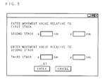
- FIG. 5 is an explanation diagram illustrating a conceptual image of a movement value input screen.
- the CPU 11 reads from the storage part 15 the movement value input screen image illustrated in FIG. 5 , and then outputs the image onto the display part 14.
- the user inputs a movement value relative to the first stack 31 as the movement value for the second stack 32.
- the user inputs a movement value relative to the second stack 32 as the movement value for the third stack 33.
- a movement value relative to the first stack 31 may be inputted as the movement value for the third stack 33.
- the CPU 11 receives the inputted movement values for the second stack 32 and the third stack 33.
- the present embodiment is described for an exemplary case that each is inputted by the unit of nm.
- the movement value may be inputted by another unit such as ⁇ m.
- the CPU 11 reads the coordinate step number per unit length stored in the storage part 15, and then multiply the coordinate step number by the movement values (length) so as to obtain movement coordinate step numbers for each of the second stack 32 and the third stack 33. Then, the CPU 11 adds to the first reference coordinates the calculated movement coordinate step numbers for the second stack 32, so as to obtain the second reference coordinates. Further, the CPU 11 adds to the second reference coordinates the movement coordinate step numbers for the third stack 33, so as to obtain the third reference coordinates. The CPU 11 stores into the coordinate value file 151 the second reference coordinates and the third reference coordinates have been calculated.
- FIG. 6 is an explanation diagram illustrating a record layout of a coordinate value file 151.
- the coordinate value file 151 stores for each set 30 the first reference coordinates of the first stack 31, the auxiliary reference coordinates of the second stack 32 (referred to as the second reference coordinates, hereinafter), and the auxiliary reference coordinates of the third stack 33 (referred to as the third reference coordinates, hereinafter).
- the coordinate value file 151 has a set ID field, a first reference coordinate field, a second reference coordinate field, and a third reference coordinate field.
- Each set ID field stores a unique ID for identifying one of the sets 30, 30, 30,....
- Each first reference coordinate field stores coordinate values where measurement on the first stack 31 is to be performed.
- the present embodiment is described for an exemplary case that coordinate values are stored. However, distances may be stored that are uniquely converted from the coordinate values.
- Each second reference coordinate field stores coordinate values where measurement on the second stack 32 is to be performed. Since the second film 302 is formed at a position deviated from the first stack 31 by a given distance, the movement value from the first reference coordinates adopted as the first reference position is inputted in advance through the input part 13. Further, the third reference coordinate field for the third stack is provided. The CPU 11 reads the coordinate step number per unit length stored in the storage part 15, and then calculates the movement coordinate step numbers. The CPU 11 adds the calculated movement coordinate step numbers to the first reference coordinates, so as to obtain the second reference coordinates. In the example of FIG. 6 , the movement coordinate step numbers are (Sx, Ty). Thus, the second reference coordinates for the set ID 01 become (x1+Sx, y1+Ty) .
- the movement coordinate step numbers of the third stack 33 relative to the second stack 32 are (Ux, Vy).
- the third reference coordinates for the set ID 01 become (x1+Sx+Ux, y1+Ty+Vy).
- the movement values may be concerning any one or both of the X-direction and the Y-direction.
- the CPU 11 controls the movement of the stage, then performs measurement on the first stack 31 at the first reference coordinates, and then performs measurement on the second stack 32 at the second reference coordinates. Similarly, measurement is performed on the third stack 33 at the third reference coordinates.
- the relevant file 154 stores relevant information indicating whether the film thickness or the optical constants of each layer constituting the first stack 31 to the third stack 33 are common to or correlated to each other. With reference to the relevant information input screen through the input part 13, the user inputs relevant information.
- FIG. 7 is an explanation diagram illustrating a conceptual image of a relevant information input screen. Models for the first stack 31 to the third stack 33 are stored in advance in the model file 153. With reference to the first (main) model to the third model stored in the model file 153, the CPU 11 generates a relevant information input screen image, and then outputs the image onto the display part 14. The first model corresponds to the first stack 31, and is constructed from the common film 300.
- the second model corresponds to the second stack 32, and is constructed from the common film 300 and the second film 302 stacked thereon.
- the third model corresponds to the third stack 33, and is constructed from the common film 300, the third film 303, and the fourth film 304 stacked thereon.
- the present embodiment is described for an exemplary case that the film thickness and the optical constants of the common film 300 are common in the parameters in the first model to the third model. Further, obviously, the film thickness or the optical constants of the second film 302 of the second model and the third film 303 of the third model which are stacked on the common film 300 may be set common.
- the CPU 11 displays check boxes 300c for lower layer and check boxes 301c for upper layer used for inputting relevant information corresponding to each layer.
- both of the film thickness and the optical constants are assumed to be common parameters. However, any one of these may solely be a common parameter.
- the CPU 11 stores these information pieces into the storage part 15.
- the film thickness and the optical constants of the common film 300 are common parameters as indicated by the corresponding check boxes 300c.
- the CPU 11 When receiving an input of the determination button 41, the CPU 11 stores into the relevant file 154 the relevant information received through the input part 13, that is, the layer and the common parameters. In the process of analysis (referred to as fitting, hereinafter), the CPU 11 performs fitting with taking such relevant information into consideration, that is, with the condition that the film thickness and the optical constants of the common film 300 are common in the first stack 31 to the third stack 33.
- fitting the process of analysis
- the CPU 11 of the computer 10 uses a modeling program stored in advance in the storage part 15. Then, models corresponding to the items of the sample 50 set up by the user and the material structure of the sample 50 are generated and then stored into the model file 153.
- a first model for the first stack 31 corresponding to the first reference position, an auxiliary model for the second stack 32 corresponding to the auxiliary reference position (referred to as a second model, hereinafter), and an auxiliary model for the third stack 33 corresponding to the auxiliary reference position (referred to as a third model, hereinafter) are stored in the model file 153.
- the CPU 11 calculates the film thickness and the complex refractive index of the common film 300 of the first stack 31. Similarly, by using the second model, the CPU 11 calculates the film thicknesses and the complex refractive indices of the common film 300 and the second film 302 of the second stack 32. Further, by using the third model, the CPU 11 calculates the film thicknesses and the complex refractive indices of the common film 300, the third film 303, and the fourth film 304 of the third stack 33.
- the amplitude ratio ⁇ and the phase difference ⁇ measured by the ellipsometer outputted from the data acquisition device 8 satisfy the relation of the following equation (3) with the film thickness d, the refractive index n, and the extinction coefficient k each of the second film 302, the third film 303, the fourth film 304, and the common film 300 to be analyzed.
- the CPU 11 of the computer 10 performs the processing (fitting) of changing the film thickness, the dispersion equation parameters, and the like such as to minimize the difference between the model spectra ( ⁇ M ( ⁇ i ), ⁇ M ( ⁇ i )) (polarization state) obtained from the stored model by theoretical calculation and the measured spectra ( ⁇ E ( ⁇ i ), ⁇ E ( ⁇ i )) (polarization state) representing the measurement result outputted from the data acquisition device 8.
- An example of an employable dispersion equation is given in the following equation (4). This dispersion equation is merely illustrative, and actual implementation is not limited to this.
- ⁇ in the left-hand part denotes the complex dielectric constant
- ⁇ ⁇ represents the dielectric constant at high frequencies (the high frequency dielectric constant)
- ⁇ s represents the dielectric constant at low frequencies (the static dielectric constant).
- ⁇ oj , ⁇ t , and ⁇ p represent the oscillator, transverse and plasma frequency respectively.
- ⁇ 0 , ⁇ D , and ⁇ j are the damping factors.
- f i represents the oscillator strength parameter.
- f j ( ⁇ sj - ⁇ ⁇ ) holds.
- the complex dielectric constant ⁇ (corresponding to ⁇ ( ⁇ )) and the complex refractive index N (corresponding to N( ⁇ )) satisfy the following equation (5).
- ⁇ ⁇ N 2 ⁇
- Mod the measurement error is assumed to have a normal distribution with a standard deviation ⁇ i .
- the mean square error ⁇ 2 according to the least square method is obtained by the following equation (6).
- P indicates the number of parameters.
- a smaller value of mean square error ⁇ 2 indicates better agreement between the measurement result and the generated model.
- a model having the smallest value of mean square error ⁇ 2 corresponds to the best model.
- model types for the sample 50 generated in advance are stored in the model file 153 in the storage part 15.
- model type structures On the basis of the processing set forth in the computer program (modeling program) stored in the storage part 15, these model type structures are read and used for analysis.
- the above-mentioned fitting based on a model is executed on each of the first stack 31 to the third stack 33.
- the CPU 11 performs fitting with taking the above-mentioned relevant information into consideration, that is, with the condition that the film thickness and the optical constants of the common film 300 are common in the first stack 31 to the third stack 33.
- the CPU 11 obtains the film thickness and the dispersion equation parameters of the common film 300 of the first stack 31.
- the CPU 11 calculates the film thickness and the dispersion equation parameters of each of the common film 300 and the second film 302 of the second stack 32.
- the CPU 11 calculates the film thickness and the dispersion equation parameters of each of the common film 300, the third film 303, and the fourth film 304 of the third stack 33.
- the film thickness of the common film 300 becomes the same in the first stack 31 to the third stack 33.
- the refractive index and the extinction coefficient of the common film 300 obtained from the film thickness and the dispersion equation parameters are common in the first stack 31 to the third stack 33.
- the CPU 11 calculates the optical constants (the refractive index n, the extinction coefficient k) of the common film 300.
- the CPU 11 calculates the optical constants (the refractive index n and the extinction coefficient k) of each of the common film 300 and the second film 302.
- the CPU 11 calculates the optical constants (the refractive index n and the extinction coefficient k) of all the films: common film 300, the third film 303, and the fourth film 304.
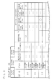
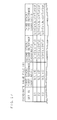
- FIG. 8 is an explanation diagram illustrating a record layout of the result DB 152.
- the result DB 152 has a set ID field, a film field, a measured spectra field, a film thickness field, abnormality flag fields for film thickness, refractive index, and extinction coefficient, a refractive index field, and an extinction coefficient field.
- the CPU 11 executes processing of storage, retrieval, and the like of necessary information in an interactive manner by using an access interface corresponding to a database format such as SQL (Structured Query Language) in a schema in which keys of the fields in the result DB 152 are related to each other.
- SQL Structured Query Language
- the result DB 152 stores the measured spectra, the film thickness, the optical constants, and the like of each of the first stack 31 to the third stack 33.
- FIG. 8 illustrates the contents of storage for the second stack 32.
- the set ID field stores each set ID described above.
- the film field stores the name of each film in the stack.
- the second film 302 serving as an upper layer and the common film 300 of the second stack 32 are stored.
- the measured spectra field stores the measured spectra ( ⁇ E ( ⁇ i ), ⁇ E ( ⁇ i )) of each film of each set ID obtained by measurement.
- the film thickness field stores the film thickness of each film of each set ID obtained by fitting between the model spectra ( ⁇ M ( ⁇ i ), ⁇ M ( ⁇ i )) (abbreviated as ⁇ M and ⁇ M , hereinafter) obtained by theoretical calculation based on the first model for the first stack 31, the second model for the second stack 32, or the third model for the third stack 33 and the measured spectra ( ⁇ E ( ⁇ i ), ⁇ E ( ⁇ i )) (abbreviated as ⁇ E and ⁇ E , hereinafter).
- the refractive index field and the extinction coefficient field respectively store the refractive index and the extinction coefficient of each film of each set ID calculated from the dispersion equation parameters obtained by fitting.
- Each abnormality flag field stores a flag indicating abnormality when each of the film thickness and the optical constants of each film of each set ID falls outside a given range of reference film thickness or reference optical constant (reference refractive index or reference extinction coefficient) stored in advance.
- each open circle indicates an abnormality flag.
- abnormality is present in the film thickness and the extinction coefficient of the second film 302 of the set ID 01.
- the reference film thickness and the given range are stored in advance in the storage part 15.
- appropriate values may be inputted through the input part 13 by the user, and then stored into the storage part 15.
- Each given range indicates an allowable error, and may be expressed, for example, as the reference film thickness ⁇ several nm. Alternatively, the range may be expressed as 99% to 101% ( ⁇ 1%) or the like of the reference film thickness.
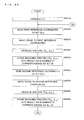
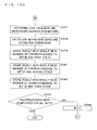
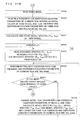
- FIGS. 9A and 9B are flow charts illustrating a procedure of measurement processing.
- the CPU 11 substitutes 1 into the variable q (step S2610).
- the CPU 11 reads from the coordinate value file 151 the first reference coordinates of the set ID q (step S2620).
- the variable q is 1, the first reference coordinates of the set ID "01" are read.
- the CPU 11 controls the first motor M1 and the second motor M2 through the motor controller 9 so as to move the stage to the first reference coordinates (step S2630). Then, measurement preparation for the first stack 31 is completed.
- the CPU 11 of the spectroscopic ellipsometer 1 controls the light irradiator 3 and the light obtainer 5 so as to irradiate light onto the first stack 31, and then acquires a measured spectra ( ⁇ E1 , ⁇ E1 ) (step S2640).
- the CPU 11 receives the measured spectra ( ⁇ E1 , ⁇ E1 ) outputted from the data acquisition device 8, and then stores the data into the result DB 152 in a manner of correspondence to the set ID (step S2650).
- the CPU 11 reads from the coordinate value file 151 the second reference coordinates of the set ID q (step S2660).
- the CPU 11 controls the first motor M1 and the second motor M2 through the motor controller 9 so as to move the stage to the second reference coordinates (step S2670).
- measurement preparation for the second stack 32 is completed.
- the CPU 11 of the spectroscopic ellipsometer 1 controls the light irradiator 3 and the light obtainer 5 so as to irradiate light onto the second stack 32, and then acquires a measured spectra ( ⁇ E2 , ⁇ E2 ) (step S2680).
- the CPU 11 receives the measured spectra ( ⁇ E2 , ⁇ E2 ) outputted from the data acquisition device 8, and then stores the data into the result DB 152 in a manner of correspondence to the set ID (step S2690).
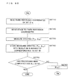
- the CPU 11 reads from the coordinate value file 151 the third reference coordinates of the set ID q (step S2710).
- the CPU 11 controls the first motor M1 and the second motor M2 through the motor controller 9 so as to move the stage to the third reference coordinates (step S2720). Then, measurement preparation for the third stack 33 is completed.
- the CPU 11 of the spectroscopic ellipsometer 1 controls the light irradiator 3 and the light obtainer 5 so as to irradiate light onto the third stack 33, and then acquires a measured spectra ( ⁇ E3 , ⁇ E3 ) (step S2730).
- the CPU 11 receives the measured spectra ( ⁇ E3 , ⁇ E3 ) outputted from the data acquisition device 8, and then stores the data into the result DB 152 in a manner of correspondence to the set ID (step S2740).
- the CPU 11 determines whether the processing has been completed for all sets 30 (step S2750). When it is determined that the processing is not yet completed for all sets 30 (NO at step S2750), the CPU 11 increments the variable q (step S2760). Then, the CPU 11 returns the procedure to step S2620, and then acquires the measured spectra of the next set 30. In contrast, when it is determined that the processing has been completed for all sets 30 (YES at step S2750), the CPU 11 terminates the series of processing.
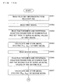
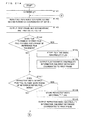
- FIGS. 11A to 11C are flow charts illustrating a procedure of fitting processing.
- the CPU 11 reads the relevant information stored in the relevant file 154 (step S361). The present embodiment is described for a case that the film thickness, the dispersion equation parameters, and the optical constants of the common film 300 are common.
- the CPU 11 reads from the model file 153 the first model stored in correspondence to the first stack 31 in advance in the storage part 15 (step S362).
- the CPU 11 reads from the storage part 15 the film thickness and the dispersion equation parameters of the common film 300 serving as the initial values of the first model stored in advance (step S363) .
- the CPU 11 calculates the model spectra ( ⁇ M1 , ⁇ M1 ) of the first model, and then stores the result into the storage part 15 (step S364).
- the CPU 11 reads from the model file 153 the second model stored in correspondence to the second stack 32 in advance in the storage part 15 (step S365).
- the CPU 11 reads from the storage part 15: the film thickness and the dispersion equation parameters of the common film 300 serving as the initial values of the second model stored in advance; and the film thickness and the dispersion equation parameters of the second film 302 serving as the initial values of the second model (step S366).
- the CPU 11 calculates the model spectra ( ⁇ M2 , ⁇ M2 ) of the second model, and then stores the result into the storage part 15 (step S367).
- the CPU 11 reads from the model file 153 the third model stored in correspondence to the third stack 33 in advance in the storage part 15 (step S368).
- the CPU 11 reads from the storage part 15: the film thickness and the dispersion equation parameters of the common film 300 serving as the initial values of the third model stored in advance; and the film thickness and the dispersion equation parameters of the third film 303 and the fourth film 304 serving as the initial values of the third model (step S369).
- the CPU 11 calculates the model spectra ( ⁇ M3 , ⁇ M3 ) of the third model, and then stores the result into the storage part 15 (step S371).
- the CPU 11 substitutes 1 into the variable q (step S372). Then, the CPU 11 reads from the result DB 152: the measured spectra ( ⁇ E1 , ⁇ E1 ) concerning the first stack 31 of the set ID q; the measured spectra ( ⁇ E2 , ⁇ E2 ) concerning the second stack 32; and the measured spectra ( ⁇ E3 , ⁇ E3 ) concerning the third stack 33 (step S373).
- the CPU 11 performs the processing (fitting) of comparing with each other the measured spectra ( ⁇ E1 , ⁇ E1 ) corresponding to (concerning) the first stack 31, the model spectra ( ⁇ M1 , ⁇ M1 ) of the first model, the measured spectra ( ⁇ E2 , ⁇ E2 ) concerning the second stack 32, the model spectra ( ⁇ M2 , ⁇ M2 ) of the second model, the measured spectra ( ⁇ E3 , ⁇ E3 ) concerning the third stack 33, and the model spectra ( ⁇ M3 , ⁇ M3 ) of the third model, which have been read for the purpose of fitting, and then changing the film thicknesses, the dispersion equation parameters, and the like such as to minimize the difference between each measured spectra and modeled spectra with the condition that the film thickness and the dispersion equation parameters of the common film 300 are the same (step S374).
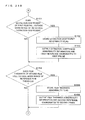
- the CPU 11 obtains a mean square error ⁇
- P1 indicates the number of parameters in the measurement of the first stack 31
- P2 indicates the number of parameters in the measurement of the second stack 32
- P3 indicates the number of parameters in the measurement of the third stack 33.
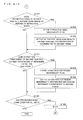
- the CPU 11 determines whether the calculated mean square error is smaller than or equal to a given value (step S375). This given value is stored in the storage part 15. When it is determined that the calculated mean square error is not smaller than or equal to the given value (NO at step S375), the CPU 11 goes to step S376.
- the CPU 11 appropriately changes the film thicknesses and the dispersion equation parameters having been set up as initial values of the models, and then re-calculates the model spectra set ⁇ M1 and ⁇ M1 , the model spectra ( ⁇ M2 , ⁇ M2 ), and the model spectra ( ⁇ M3 , ⁇ M3 ) (step S376).
- the CPU 11 determines the film thickness and the dispersion equation parameters of the first stack 31, the film thickness and the dispersion equation parameters of each layer of the second stack 32, and the film thickness and the dispersion equation parameters of each layer of the third stack 33 (step S377).
- the film thickness of the common film 300 becomes the same in the first stack 31 to the third stack 33.
- the refractive index and the extinction coefficient of the common film 300 obtained from the dispersion equation parameters are common in the first stack 31 to the third stack 33.
- the CPU 11 calculates the refractive index and the extinction coefficient of the common film 300 of the first stack 31, then with reference to the dispersion equation parameters and the like of the common film 300 and the second film 302, calculates the refractive indices and the extinction coefficients of the common film 300 and the second film 302 of the second stack 32, and then with reference to the dispersion equation parameters and the like of the common film 300, the third film 303, and the fourth film 304, calculates the refractive indices and the extinction coefficients of the common film 300, the third film 303, and the fourth film 304 of the third stack 33 (step S378).
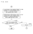
- the CPU 11 stores into the result DB 152 the film thickness, the refractive index, and the extinction coefficient of the common film 300 in a manner of correspondence to the set ID and the first stack 31 (step S379). Similarly, the CPU 11 stores into the result DB 152 the film thickness, the refractive index, and the extinction coefficient of each of the common film 300 and the second film 302 in a manner of correspondence to the set ID and the second stack 32 (step S381). The CPU 11 stores into the result DB 152 the film thickness, the refractive index, and the extinction coefficient of each of the common film 300, the third film 303, and the fourth film 304 in a manner of correspondence to the set ID and the third stack 33 (step S382).
- the CPU 11 determines whether the processing has been completed for all sets 30 (step S383). When it is determined that the processing is not yet completed for all sets 30 (NO at step S383), the CPU 11 increments the variable q (step S384). The CPU 11 returns the procedure to step S373 so as to perform fitting on the next set 30. In contrast, when it is determined that the processing has been completed for all sets 30 (YES at step S383), the CPU 11 terminates the series of processing.
- FIG. 11 is a block diagram illustrating a hardware configuration of an optical measurement apparatus according to Embodiment 2.
- the optical measurement apparatus 1 measuring a change in the state of light is, for example, a spectroscopic ellipsometer, a polarimeter, an interferometer, or an apparatus constructed from a combination of these.
- the following description is given for an example that the optical measurement apparatus 1 is a spectroscopic ellipsometer 1.
- the spectroscopic ellipsometer 1 is constructed from a xenon lamp 2, a light irradiator 3, a stage 4, a light obtainer 5, a spectrometer 7, a data acquisition device 8, a motor controller 9, a computer 10, and the like.
- the spectroscopic ellipsometer 1 measures a sample 50 in which individual sets each composed of a plurality of regularly arranged stacks having common layers in part are distributed.
- the spectroscopic ellipsometer 1 irradiates polarized light onto the sample 50 formed by depositing (stacking) a plurality of films, then acquires light reflected by the sample 50, and measures the polarization state of the reflected light. Then, on the basis of the measurement result and a model corresponding to the sample 50, the spectroscopic ellipsometer 1 analyzes the characteristics of each film layer of the sample 50.
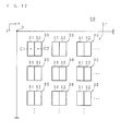
- FIG. 12 is a plan view of the sample 50 according to Embodiment 2.
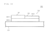
- FIG. 13 is a schematic cross section of the sample 50 according to Embodiment 2.
- the sample 50 contains a substrate 51 and sets 30, 30, 30, 30,....
- the substrate 51 is a transparent substrate composed of glass, plastics, or the like, or alternatively, is a plastic plate or film, a flexible metal substrate, or a wafer.
- a common film referred to as a lower layer film 300 is formed by CVD (Chemical Vapor Deposition), ALD (Atomic Layer Deposition), thermal oxidation, sputtering, or the like.
- the lower layer film 300 is a silicon oxide film (SiO2) formed on a wafer by CVD.
- a first film 301 is formed on one part of the upper surface of the lower layer film 300.
- the first film 301 is an amorphous silicon film, and is formed on the lower layer film 300 by CVD or the like.
- a second film 302 is formed on the other part of the upper surface of the lower layer film 300.
- the second film 302 is composed of a material different from that of the first film, and is a polysilicon film or the like formed on the lower layer film 300 by CVD or the like.
- the stack obtained by stacking the first film 301 on the lower layer film 300 is referred to as a first stack 31, while the stack obtained by stacking the second film 302 on the lower layer film 300 is referred to as a second stack 32. Further, the combination of the first stack 31 and the second stack 32 is referred to as a set 30.
- the present embodiment is described for an exemplary case that the lower layer film 300 common in the first stack 31 and the second stack 32 is composed of a single layer.
- actual implementation is not limited to this. That is, it is sufficient that the lower layer film 300 is common in the first stack 31 and the second stack 32, and hence the lower layer film 300 may be formed by stacking a plurality of films.
- the lower layer film 300 may be replaced by a plurality of films that surround the upper side and the lower side of the first film 301 and the second film 302.
- electrodes, a protective cover, or the like may be added (formed) to the first stack 31 and the second stack 32.
- the first film 301 and the second film 302 are formed from mutually different substances whose film thicknesses or optical characteristics including each refractive index and each extinction coefficient are different from each other.
- the present embodiment is described for an exemplary case that the first film 301 and the second film 302 are formed from mutually different substances whose film thicknesses and optical constants are different from each other.
- the sets 30 are distributed on the plane of the substrate 51 surface. In the following description, an upper left point in the plan view of the substrate 51 is adopted as the origin having coordinates (0, 0). Then, the rightward direction from the origin is adopted as the positive X-direction, while the downward direction from the origin is adopted as the positive Y-direction.
- the first stacks 31 and the second stacks 32 constituting the sets 30 are formed and distributed at given coordinate positions in accordance with the circuit design.
- the measurement is performed around the first reference coordinates adopted as the first reference position C1.
- the measurement is performed around auxiliary reference coordinates adopted as an auxiliary reference position C2.
- the measurement point has been set up approximately at the center of each of the first stack 31 and the second stack 32.
- this setting is merely illustrative, and actual implementation is not limited to this.
- the first reference coordinates adopted as the formation position of the first stack 31 are stored in advance.
- the spectroscopic ellipsometer 1 analyzing the first stack 31 and the second stack 32 of the sample 50 having the structure described above is divided roughly into a measurement and analysis part and a drive part.
- the former part includes a measuring apparatus composed of a pair of the light irradiator 3 and the light obtainer 5.
- the xenon lamp 2 and the light irradiator 3 are connected to each other through a first optical fiber cable 15a.
- the spectroscopic ellipsometer 1 irradiates polarized light onto the sample 50 placed on the stage 4, and then acquires reflected light from the sample 50 by means of the light obtainer 5.
- the light obtainer 5 is connected to the spectrometer 7 through a second optical fiber cable 15b.
- the spectrometer 7 performs measurement for each wavelength, and then transmits the measurement result in the form of an analog signal to the data acquisition device 8.
- the data acquisition device 8 converts the analog signal into a necessary value, and then transmits the data to the computer 10.
- the computer 10 performs analysis.
- a first motor M1 to a sixth motor M6 are provided in the stage 4, the light irradiator 3, the light obtainer 5, and the spectrometer 7.
- the driving of the first motor M1 to the sixth motor M6 is controlled by the motor controller 9 connected to the computer 10, so that the stage 4, the light irradiator 3, the light obtainer 5, and the spectrometer 7 are controlled into appropriate positions and orientations in accordance with the measurement.
- the motor controller 9 controls the driving of the first motor M1 to the sixth motor M6.
- the xenon lamp 2 is a light source, and generates white light containing a plurality of wavelength components.
- the generated white light is transferred to the light irradiator 3 through the first optical fiber cable 15a.
- the light irradiator 3 is arranged on a half circular arc rail 6, and has a polarizer 3a in the inside.
- the white light is polarized by the polarizer 3a, and then the polarization light is irradiated onto the sample 50.
- the light irradiator 3 moves along the rail 6 when the fourth motor M4 is driven. This permits adjustment of the angle (incident angle ⁇ ) of the irradiated light relative to the perpendicular line H to the stage surface 4a of the stage 4.
- the stage 4 is arranged in a slidable manner on a movement rail portion (not illustrated). Then, when the first motor M1 to the third motor M3 are driven, the stage 4 moves respectively in the X-direction, the Y-direction (a direction perpendicular to the page of FIG. 11 ), the Z-direction serving as the height direction in FIG. 11 .
- the movement of the stage 4 permits desired setting of the position of light incidence onto the sample 50, and hence surface analysis of the sample 50 is achieved.
- the present embodiment is described for an exemplary case that the stage 4 is moved in the X-direction and the Y-direction.
- actual implementation is not limited to this.
- the stage 4 may be fixed.
- the light irradiator 3 and the light obtainer 5 may be moved so that the irradiation position may be moved in the X-direction and the Y-direction. Further, the stage surface 4a of the stage 4 on which the sample 50 is placed is black-colored in order to avoid reflection of light.
- the light obtainer 5 acquires the light reflected by the sample 50, and then measures the polarization state of the acquired light.
- the light obtainer 5 is arranged on the rail 6 similarly to the light irradiator 3, and includes a PEM (Photo Elastic Modulator) 5a and an analyzer 5b. Then, the light reflected by the sample 50 is guided to the analyzer 5b through the PEM 5a.
- the light obtainer 5 is allowed to move along the rail 6 by the driving of the fifth motor M5.
- the light obtainer 5 is controlled in linkage with the movement of the light irradiator 3 by the motor controller 9 such that the reflection angle ⁇ becomes equal to the incident angle ⁇ .
- the PEM 5a provided in the light obtainer 5 performs phase modulation on the acquired light at a necessary frequency (for example, 50 kHz), so that elliptically polarized light is obtained from the linearly polarized light. Further, the analyzer 5b acquires and measures a polarized light component selectively from the various polarized light components obtained by the phase modulation in the PEM 5a.
- a necessary frequency for example, 50 kHz
- the spectrometer 7 includes a reflection mirror, a diffraction grating, a photo multiplier (PMT: Photo Multiplier Tube), and a control unit.
- PMT Photo Multiplier Tube
- the light transferred from the light obtainer 5 through the second optical fiber cable 15b is reflected by the reflection mirror and guided onto the diffraction grating.
- the angle of the diffraction grating is adjusted by the sixth motor M6, so that the wavelength of the emitted light is adjusted.
- the light advanced to the inside of the spectrometer 7 is amplified by the PMT so that the measurement signal (light) is stabilized even in the case of a low light intensity.
- the control unit generates an analog signal corresponding to the measurement wavelength, and then transmits the signal to the data acquisition device 8.
- the data acquisition device 8 calculates the amplitude ratio ⁇ and the phase difference ⁇ of the polarization states (p-polarization and s-polarization) of the reflected light for each wavelength, and then transmits the calculated results to the computer 10.
- the amplitude ratio ⁇ and the phase difference ⁇ satisfy the relation of the above-mentioned equation (1) for the complex reflection coefficient Rp of p-polarization and the complex reflection coefficient Rs of s-polarization.
- the computer 10 analyzes the sample 50 on the basis of the amplitude ratio ⁇ and the phase difference ⁇ of the polarization states obtained by the data acquisition device 8 and on the basis of a model corresponding to the sample.
- the computer 10 further controls the movement of the stage 4 and the like.
- the computer 10 includes a CPU (Central Processing Unit) 11, a display part 14, an input part 13, a storage part 15, a clock part 11e, and a RAM (Random Access Memory) 12.
- the CPU 11 is connected to the individual hardware parts of the computer 10 through a bus, and controls these parts.
- the CPU 11 further executes various kinds of software-based functions in accordance with various kinds of programs stored in the storage part 15.
- the RAM 12 is a semiconductor device or the like, and writes and reads necessary information in accordance with instructions from the CPU 11.
- the display part 14 is a liquid crystal display unit, an organic electroluminescence display unit, or the like.
- the input part 13 is constructed from a keyboard, a mouse, and the like.
- the input part 13 may be a touch panel stacked on the display part 14.
- the clock part 11e outputs date and time information to the CPU 11.
- the storage part 15 is constructed from a hard disk, a large-capacity memory, or the like, and stores, in advance, various kinds of programs like computer programs for analysis and computer programs for movement control for the stage 4.
- the storage part 15 further stores: data of various kinds of menu images to be displayed on the display part 14; known data concerning the sample 50; a plurality of models; a plurality of dispersion equations used for generating models; generated models; reference data corresponding to various kinds of samples; reference values used in comparison processing concerning interference fringes; and the like.
- the storage part 15 stores a coordinate value file 151, a result database (DB, hereinafter) 152, a model file 153, and the like.
- these files and DB may be stored in a DB server or the like not illustrated.
- the computer 10 analyzes the refractive indices and the extinction coefficients (collectively referred to as optical constants, in some cases hereinafter) as the optical characteristics of: the lower layer film 300 and the first film 301 constitutes the first stack 31; and the lower layer film 300 and the second film 302 constitutes the second stack 32.
- the computer 10 analyzes also the film thicknesses and the like of these layers.
- the CPU 11 With reference to the coordinate value file 151, the CPU 11 successively moves the stage and performs measurement of the first stack 31 and the second stack 32.
- FIG. 14 is an explanation diagram illustrating a record layout of the coordinate value file 151 according to Embodiment 2.
- the coordinate value file 151 stores for each set 30 the first reference coordinates of the first stack 31 and the auxiliary reference coordinates of the second stack 32 (referred to as the second reference coordinates, hereinafter).
- the coordinate value file 151 has a set ID field, a first reference coordinate field, and a second reference coordinate field.
- Each set ID field stores a unique ID for identifying one of the sets 30, 30, 30,....
- Each first reference coordinate field stores coordinate values where measurement on the first stack 31 is to be performed.
- the present embodiment is described for an exemplary case that coordinate values are stored. However, distances may be stored that are uniquely converted from the coordinate values.
- Each second reference coordinate field stores coordinate values where measurement on the second stack 32 is to be performed. Since the second film 302 is formed at a position deviated from the first film 301 by a given distance, the movement value from the first reference coordinates adopted as the first reference position is inputted in advance through the input part 13.
- FIG. 15 is an explanation diagram illustrating a conceptual image of a movement value input screen according to Embodiment 2.
- the CPU 11 reads from the storage part 15 the movement value input screen image illustrated in FIG. 15 , and then outputs the image onto the display part 14.
- the user inputs a movement value through the input part 13.
- the CPU 11 receives the inputted movement values.
- the present embodiment is described for an exemplary case that each is inputted by the unit of nm. However, the movement value may be inputted by another unit such as ⁇ m.
- the CPU 11 reads the coordinate step number per unit length stored in the storage part 15, and then calculates the movement coordinate step numbers.
- the CPU 11 adds the calculated movement coordinate step numbers to the first reference coordinates, so as to obtain the second reference coordinates.
- the movement coordinate step numbers are (Sx, Ty).
- the second reference coordinates for the set ID 01 become (x1+Sx, y1+Ty).
- the movement values may be concerning any one or both of the X-direction and the Y-direction.
- the CPU 11 controls the movement of the stage, then performs measurement on the first stack 31 at the first reference coordinates, and then performs measurement on the second stack 32 at the second reference coordinates.
- the CPU 11 of the computer 10 uses a modeling program stored in advance in the storage part 15. Then, models corresponding to the items of the sample 50 set up by the user and the material structure of the sample 50 are generated and then stored into the model file 153.
- a first model for the first stack 31 corresponding to the first reference position and an auxiliary model for the second stack 32 corresponding to the auxiliary reference position are stored in the model file 153.
- the CPU 11 calculates the film thicknesses and the complex refractive indices of the lower layer film 300 and the first film 301 of the first stack 31. Similarly, by using the second model, the CPU 11 calculates the film thicknesses and the complex refractive indices of the lower layer film 300 and the second film 302 of the second stack 32.
- the amplitude ratio ⁇ and the phase difference ⁇ measured by the ellipsometer outputted from the data acquisition device 8 satisfy the relation of the above-mentioned equation (3) with the film thickness d, the refractive index n, and the extinction coefficient k each of the first film 301, the second film 302, and the lower layer film 300 to be analyzed.
- the CPU 11 of the computer 10 performs the processing (fitting) of changing the film thickness, the dispersion equation parameters, and the like such as to minimize the difference between the model spectra ( ⁇ M ( ⁇ i ), ⁇ M ( ⁇ i )) (polarization state) obtained from the stored model by theoretical calculation and the measured spectra ( ⁇ E ( ⁇ i ), ⁇ E ( ⁇ i )) (polarization state) representing the measurement result outputted from the data acquisition device 8.
- an example of an employable dispersion equation is equation (4) given above.
- Equation (4) in the left-hand part denotes the complex dielectric constant, while ⁇ ⁇ represents the dielectric constant at high frequencies (the high frequency dielectric constant), and ⁇ s represents the dielectric constant at low frequencies (the static dielectric constant).
- ⁇ oj , ⁇ t , and ⁇ p represent the oscillator, transverse and plasma frequency respectively.
- ⁇ 0 , ⁇ D , and ⁇ j are the damping factors.
- f i represents the oscillator strength parameter.
- f j ( ⁇ sj - ⁇ ⁇ ) holds.
- the complex dielectric constant ⁇ (corresponding to ⁇ ( ⁇ )) and the complex refractive index N (corresponding to N( ⁇ )) satisfy the equation (5) given above.
- the measurement error is assumed to have a normal distribution with a standard deviation ⁇ i .
- the mean square error ⁇ 2 according to the least square method is obtained by equation (6) given above.
- P indicates the number of parameters.
- a smaller value of mean square error ⁇ 2 indicates better agreement between the measurement result and the generated model.
- a model having the smallest value of mean square error ⁇ 2 corresponds to the best model.
- model types for the sample 50 generated in advance are stored in the model file 153 in the storage part 15.
- model type structures On the basis of the processing set forth in the computer program (modeling program) stored in the storage part 15, these model type structures are read and used for analysis.
- the above-mentioned fitting based on a model is executed on each of the first stack 31 and the second stack 32.
- the CPU 11 obtains the film thickness and the dispersion equation parameters of each of the lower layer film 300 and the first film 301 of the first stack 31.
- the CPU 11 calculates the film thickness and the dispersion equation parameters of each of the lower layer film 300 and the second film 302 of the second stack 32.
- the CPU 11 calculates the optical constants (the refractive index n and the extinction coefficient k) of each of the lower layer film 300 and the first film 301.
- the CPU 11 calculates the optical constants (the refractive index n and the extinction coefficient k) of each of the lower layer film 300 and the second film 302.
- FIG. 16 is an explanation diagram illustrating a record layout of the result DB 152 according to Embodiment 2.
- the result DB 152 has a set ID field, a film field, a measured spectra field, a film thickness field, abnormality flag fields for film thickness, refractive index, and extinction coefficient, a refractive index field, and an extinction coefficient field.
- the CPU 11 executes processing of storage, retrieval, and the like of necessary information in an interactive manner by using an access interface corresponding to a database format such as SQL (Structured Query Language) in a schema in which keys of the fields in the result DB 152 are related to each other.
- SQL Structured Query Language
- the result DB 152 stores the measured spectra, the film thickness, the optical constants, and the like of each of the first stack 31 and the second stack 32.
- the example of FIG. 16 illustrates the contents of storage for the first stack 31.
- the set ID field stores each set ID described above.
- the film field stores the name of each film constituting the stack.
- the first film 301 serving as an upper layer and the lower layer film 300 of the first stack 31 are stored.
- the measured spectra field stores the measured spectra ( ⁇ E ( ⁇ i ), ⁇ E ( ⁇ i )) of each film of each set ID obtained by measurement.
- the film thickness field stores the film thickness of each film of each set ID obtained by fitting between the model spectra ( ⁇ M ( ⁇ i ), ⁇ M ( ⁇ i )) (abbreviated as ⁇ M and ⁇ M , hereinafter) obtained by theoretical calculation based on the first model for the first stack 31 or the second model for the second stack 32 and the measured spectra ( ⁇ E( ⁇ i ), ⁇ E ( ⁇ i )) (abbreviated as ⁇ E and ⁇ E , hereinafter).
- the refractive index field and the extinction coefficient field respectively store the refractive index and the extinction coefficient of each film of each set ID calculated from the dispersion equation parameters obtained by fitting.
- Each abnormality flag field stores a flag indicating abnormality when each of the film thickness and the optical constants of each film of each set ID falls outside a given range of reference film thickness or reference optical constant (reference refractive index or reference extinction coefficient) stored in advance.
- each open circle indicates an abnormality flag.
- abnormality is present in the film thickness and the extinction coefficient of the first film 301 of the set ID 01.
- the reference film thickness and the given range are stored in advance in the storage part 15.
- appropriate values may be inputted through the input part 13 by the user, and then stored into the storage part 15.
- Each given range indicates an allowable error, and may be expressed, for example, as the reference film thickness ⁇ several nm. Alternatively, the range may be expressed as 99% to 101% ( ⁇ 1%) or the like of the reference film thickness.
- the exemplary layout of the result DB 152 is merely illustrative. Thus, as long as the relation between data pieces is maintained, arbitrary data layout may be adopted depending on the design.
- the CPU 11 When measurement processing has been completed on all sets 30, the CPU 11 outputs a result onto the display part 14.
- FIG. 17 is an explanation diagram illustrating a conceptual image of a result display screen according to Embodiment 2.
- the CPU 11 With reference to the first reference coordinates and the second reference coordinates in the coordinate value file 151, the CPU 11 outputs, onto the display part 14, rectangular frames each indicating the first stack 31 and the second stack 32 constituting each set 30. As illustrated in FIG. 17 , frames indicating the first stacks 31 and frames indicating the second stacks 32 are displayed on the display part 14 together with set IDs indicating the sets 30.
- the CPU 11 searches abnormality flags concerning the film thickness, the refractive index, and the extinction coefficient of each film other than the lower layer film 300, that is, of each of the first films 301 and the second films 302. When an abnormality flag is set up concerning the film thickness of a first film 301, the CPU 11 displays "d" indicating the film thickness, into a frame concerning the first film of the corresponding set ID.
- the CPU 11 displays "n” indicating the refractive index, into a frame concerning the first film of the corresponding set ID. Further, when an abnormality flag is set up concerning the extinction coefficient of a first film 301, the CPU 11 displays "k” indicating the extinction coefficient, into a frame concerning the first film of the corresponding set ID. Similarly, as for the second films 302, a signal “d", "n", or "k” indicating the abnormality is outputted into a frame concerning the second film of the corresponding set ID.
- the CPU 11 outputs onto the display part 14 the coordinate values of the first stack 31 or the second stack 32 in which at least one abnormality flag is set up.
- abnormality is present in the film thickness of the first film 301 concerning the first stack 31 of the set ID 01 indicated by the first reference coordinates (x1, y1).
- abnormality is present in all of the film thickness, the refractive index, and the extinction coefficient of the second film 302 concerning the second stack 32 of the set ID 07 indicated by the second reference coordinates (x7+Sx, y7+Ty). As illustrated in FIG.
- the present embodiment has been described for an exemplary case that abnormality is present in the first stacks 31 and the second stacks 32 serving as upper layers.
- the abnormality state of the lower layer film 300 serving as a lower layer may similarly be illustrated.
- the CPU 11 When the hyperlink "Lower layer" displayed in FIG. 17 is clicked, the CPU 11 performs the following processing. With reference to the first reference coordinates in the coordinate value file 151, the CPU 11 outputs, onto the display part 14, rectangular frames indicating the lower layer films 300. Similarly to the display for the first stacks 31 and the second stacks 32, frames indicating the lower layer films 300 and set IDs indicating the sets 30 are displayed on the display part 14.
- the CPU 11 searches abnormality flags concerning the film thickness, the refractive index, and the extinction coefficient of each lower layer film 300.
- the CPU 11 displays "d” indicating the film thickness, into the frame of the corresponding set ID.
- the CPU 11 displays "n” indicating the refractive index, into the frame of the corresponding set ID.
- the CPU 11 displays "k” indicating the extinction coefficient, into the frame of the corresponding set ID.
- the CPU 11 outputs onto the display part 14 the coordinate values of the lower layer film 300 in which at least one abnormality flag is set up.
- the screen displaying abnormality in the lower layer film 300 and the screen displaying abnormality in the first stack 31 and the second stack 32 have been illustrated separately. However, obviously, these screens may be integrated into one.
- FIG. 18 is a flow chart illustrating a procedure of storage processing for coordinate values according to Embodiment 2.
- the CPU 11 receives the first reference position of the first stack 31 of each set 30 (step S81). As for the first reference position, the user may input appropriate numerical values through the input part 13. Alternatively, the CPU 11 may receive a first reference position acquired by reading a recording medium (not illustrated) or a first reference position acquired by download through a communication network. With reference to the coordinate value per unit length stored in the storage part 15, the CPU 11 calculates the first reference coordinates of each set 30 corresponding to the first received reference position (step S82).
- the CPU 11 stores into the coordinate value file 151 the calculated first reference coordinates in a manner of correspondence to the set ID (step S83).
- the CPU 11 reads the movement value input screen image stored in the storage part 15, and then outputs the image onto the display part 14.
- the CPU 11 receives the movement value inputted through the input part 13 (step S84).
- the CPU 11 calculates the second reference coordinates of each set (step S85).
- the CPU 11 stores into the coordinate value file 151 the second reference coordinates in a manner of correspondence to the set ID (step S86).
- FIGS. 19A and 19B are flow charts illustrating a procedure of measurement processing according to Embodiment 2.
- the CPU 11 substitutes 1 into the variable q (step S91).
- the CPU 11 reads from the coordinate value file 151 the first reference coordinates of the set ID q (step S92).
- the variable q is 1, the first reference coordinates of the set ID "01" are read.
- the CPU 11 controls the first motor M1 and the second motor M2 through the motor controller 9 so as to move the stage to the first reference coordinates (step S93). Then, measurement preparation for the first stack 31 is completed.
- the CPU 11 of the spectroscopic ellipsometer 1 controls the light irradiator 3 and the light obtainer 5 so as to irradiate light onto the first stack 31, and then acquires a measured spectra ( ⁇ E1 , ⁇ E1 ) (step S94).
- the CPU 11 receives the measured spectra ( ⁇ E1 , ⁇ E1 ) outputted from the data acquisition device 8, and then stores the data into the result DB 152 in a manner of correspondence to the set ID (step S95).
- the CPU 11 outputs the measured spectra ( ⁇ E1 , ⁇ E1 ) to the modeling program (step S96).
- the fitting processing is described later.
- the CPU 11 reads from the coordinate value file 151 the second reference coordinates of the set ID q (step S97).
- the CPU 11 controls the first motor M1 and the second motor M2 through the motor controller 9 so as to move the stage to the second reference coordinates (step S98). Then, measurement preparation for the second stack 32 is completed.
- the CPU 11 of the spectroscopic ellipsometer 1 controls the light irradiator 3 and the light obtainer 5 so as to irradiate light onto the second stack 32, and then acquires a measured spectra ( ⁇ E2 , ⁇ E2 ) (step S99).
- the CPU 11 receives the measured spectra ( ⁇ E2 , ⁇ E2 ) outputted from the data acquisition device 8, and then stores the data into the result DB 152 in a manner of correspondence to the set ID (step S101). Here, analysis need not be performed immediately after the measurement, and may be performed later. For the purpose of fitting, the CPU 11 outputs the measured spectra ( ⁇ E2 , ⁇ E2 ) to the modeling program (step S102). The CPU 11 determines whether the processing has been completed for all sets 30 (step S103). When it is determined that the processing is not yet completed for all sets 30 (NO at step S103), the CPU 11 increments the variable q (step S104).
- the CPU 11 returns the procedure to step S92, and then acquires the measured spectra of the next set 30. In contrast, when it is determined that the processing has been completed for all sets 30 (YES at step S103), the CPU 11 terminates the series of processing.
- FIGS. 24A to 24C are flow charts illustrating a procedure of calculating a film thickness and optical constants according to Embodiment 2.
- the CPU 11 reads the first model from the model file 153 (step S111).
- the CPU 11 reads from the storage part 15 a plurality of film thicknesses and a plurality of dispersion equation parameters serving as the initial values stored in advance (step S112).
- the CPU 11 calculates the model spectra ( ⁇ M1 , ⁇ M1 ) of the first model, and then stores the result into the storage part 15 (step S113).
- the CPU 11 reads the second model from the model file 153 (step S114).
- the CPU 11 reads from the storage part 15 a plurality of film thicknesses and a plurality of dispersion equation parameters serving as the initial values stored in advance (step S115).
- the CPU 11 calculates the model spectra ( ⁇ M2 , ⁇ M2 ) of the second model, and then stores the result into the storage part 15 (step S116).
- the CPU 11 substitutes 1 into the variable q (step S117).
- the CPU 11 reads from the result DB 152 the measured spectra ( ⁇ E1 , ⁇ E1 ) of the set ID q (step S118).
- the CPU 11 performs fitting (step S119).
- the CPU 11 performs the processing (fitting) of comparing with each other the measured spectra ( ⁇ E1 , ⁇ E1 ) and the model spectra ( ⁇ M1 , ⁇ M1 ) of the first model having been read for the fitting, and then changing the film thickness, the dispersion equation parameters, and the like so as to minimize the difference between the measured spectra and the model spectra.
- the CPU 11 obtains a mean square error ⁇ 2 according to the least square method.
- the mean square error ⁇ 2 is calculated in accordance with equation (2) given above.
- the CPU 11 determines whether the calculated mean square error is smaller than or equal to a given value (step S121). This given value is stored in the storage part 15. When it is determined that the calculated mean square error is not smaller than or equal to the given value (NO at step S121), the CPU 11 appropriately changes the film thickness and the dispersion equation parameters having been set up as initial values in the first model, and then re-calculates the model spectra ( ⁇ M1 , ⁇ M1 ) of the first model (step S122). This change may be performed by the CPU 11, or alternatively by the operator. After that, the procedure goes to step S119 again, so that similar processing is repeated.
- the CPU 11 determines that the film thickness and the dispersion equation parameters obtained at that time by fitting are the values to be adopted (step S123). As a result, the film thickness of each of the lower layer film 300 and the first film 301 of the first stack 31 is obtained.
- the processing is performed until the value becomes smaller than or equal to the given value.
- actual implementation is not limited to this.
- the initial film thickness and dispersion equation parameters to be set into each model within a given time may be changed successively, and then a film thickness and dispersion equation parameters realized at the time when the minimum mean square error is obtained within the given time may be adopted as the obtained result.
- the CPU 11 calculates the refractive index and the extinction coefficient of each of the lower layer film 300 and the first film 301 of the first stack 31 (step S124).
- the CPU 11 stores into the result DB 152 the film thickness, the refractive index, and the extinction coefficient of each of the lower layer film 300 and the first film 301 in a manner of correspondence to the set ID and the first stack 31 (step S125).
- the CPU 11 reads from the result DB 152 the measured spectra ( ⁇ E2 , ⁇ E2 ) of the set ID q (step S126). On the basis of the read-out measured spectra ( ⁇ E2 , ⁇ E2 ) and the model spectra ( ⁇ M2 , ⁇ M2 ) of the second model, the CPU 11 performs fitting (step S127).
- the CPU 11 performs the processing (fitting) of comparing with each other the measured spectra ( ⁇ E2 , ⁇ E2 ) and the model spectra ( ⁇ M2 , ⁇ M2 ) of the second model having been read for the fitting, and then changing the film thickness, the dispersion equation parameters, and the like so as to minimize the difference between the measured spectra and the model spectra.
- the CPU 11 obtains a mean square error ⁇ 2 according to the least square method.
- the mean square error ⁇ 2 is calculated in accordance with equation (2) given above.
- the CPU 11 determines whether the calculated mean square error is smaller than or equal to a given value (step S128). When it is determined that the calculated mean square error is not smaller than or equal to the given value (NO at step S128), the CPU 11 appropriately changes the film thickness and the dispersion equation parameters having been set up as initial values in the second model, and then re-calculates the model spectra ( ⁇ M2 , ⁇ M2 ) of the second model (step S129). After that, the procedure goes to step S127 again, so that similar processing is repeated.
- the CPU 11 determines that the film thickness and the dispersion equation parameters obtained at that time by fitting are the values to be adopted (step S131). As a result, the film thickness of each of the lower layer film 300 and the second film 302 of the second stack 32 is obtained. With reference to the dispersion equation parameters and the like of the lower layer film 300 and the second film 302, the CPU 11 calculates the refractive index and the extinction coefficient of each of the lower layer film 300 and the second film 302 concerning the second stack 32 (step S132). The CPU 11 stores into the result DB 152 the film thickness, the refractive index, and the extinction coefficient of each of the lower layer film 300 and the second film 302 in a manner of correspondence to the set ID and the second stack 32 (step S133).
- the CPU 11 determines whether the processing has been completed for all sets 30 (step S134). When it is determined that the processing is not yet completed for all sets 30 (NO at step S134), the CPU 11 increments the variable q (step S135). The CPU 11 returns the procedure to step S118 so as to perform calculation of the film thickness and the optical constants of the next set 30. In contrast, when it is determined that the processing has been completed for all sets 30 (YES at step S134), the CPU 11 terminates the series of processing. According to this approach, merely when the coordinate value file 151 is generated and the corresponding models are prepared in the beginning, the film thicknesses and the optical constants of the first stack 31 and the second stack 32 of each set 30 serving as a measurement object are acquired.
- FIGS. 21A to 21C are flow charts illustrating a procedure of abnormality detection processing according to Embodiment 2.
- the CPU 11 substitutes an initial value 1 into the variable q (step S141).
- the CPU 11 reads from the coordinate value file 151 the first reference coordinates and the second reference coordinates of the set ID q (step S142). With reference to the first reference coordinates and the second reference coordinates, the CPU 11 outputs, onto the display part 14, two rectangular frames illustrated in FIG. 17 . Specifically, with reference to the first reference coordinates, the CPU 11 outputs a first frame corresponding to the first stack 31, and then with reference to the second reference coordinates, outputs a second frame corresponding to the second stack 32. Further, the CPU 11 outputs the set ID in the vicinity (step S143).
- the CPU 11 reads the film thickness of the first film 301 corresponding to the set ID q stored in the result DB 152.
- the CPU 11 determines whether the film thickness of the first film 301 falls outside a given range for the reference film thickness stored in advance in the storage part 15 (step S144). When it is determined as falling outside the given range (YES at step S144), the CPU 11 stores into the result DB 152 the film thickness abnormality flag in correspondence to the first film 301 of the set ID q (step S145).
- the CPU 11 outputs, into the first frame, information indicating the abnormality in the film thickness and the first reference coordinates corresponding to the set ID stored in the coordinate value file 151 (step S146). After this processing, or alternatively when it is determined as not falling outside the given range (NO at step S144), the CPU 11 moves the procedure to step S147.
- the CPU 11 reads the refractive index of the first film 301 corresponding to the set ID q stored in the result DB 152.
- the CPU 11 determines whether the refractive index of the first film 301 falls outside a given range for the reference refractive index stored in advance in the storage part 15 (step S147). When it is determined as falling outside the given range (YES at step S147), the CPU 11 stores into the result DB 152 the refractive index abnormality flag in correspondence to the first film 301 of the set ID q (step S148).
- the CPU 11 outputs, into the first frame, information indicating the abnormality in the refractive index and the first reference coordinates corresponding to the set ID stored in the coordinate value file 151 (step S149).
- the CPU 11 moves the procedure to step S151.
- the CPU 11 reads the extinction coefficient of the first film 301 corresponding to the set ID q stored in the result DB 152.
- the CPU 11 determines whether the extinction coefficient of the first film 301 falls outside a given range for the reference extinction coefficient stored in advance in the storage part 15 (step S151). When it is determined as falling outside the given range (YES at step S151), the CPU 11 stores into the result DB 152 the extinction coefficient abnormality flag in correspondence to the first film 301 of the set ID q (step S152).
- the CPU 11 outputs, into the first frame, information indicating the abnormality in the extinction coefficient and the first reference coordinates corresponding to the set ID stored in the coordinate value file 151 (step S153). After this processing, or alternatively when it is determined as not falling outside the given range (NO at step S151), the CPU 11 moves the procedure to step S154.
- the CPU 11 reads the film thickness of the second film 302 corresponding to the set ID q stored in the result DB 152.
- the CPU 11 determines whether the film thickness of the second film 302 falls outside a given range for the reference film thickness stored in advance in the storage part 15 (step S154). When it is determined as falling outside the given range (YES at step S154), the CPU 11 stores into the result DB 152 the film thickness abnormality flag in correspondence to the second film 302 of the set ID q (step S155).
- the CPU 11 outputs, into the second frame, information indicating the abnormality in the film thickness and the second reference coordinates corresponding to the set ID stored in the coordinate value file 151 (step S156). After this processing, or alternatively when it is determined as not falling outside the given range (NO at step S154), the CPU 11 moves the procedure to step S157.
- the CPU 11 reads the refractive index of the second film 302 corresponding to the set ID q stored in the result DB 152.
- the CPU 11 determines whether the refractive index of the second film 302 falls outside a given range for the reference refractive index stored in advance in the storage part 15 (step S157). When it is determined as falling outside the given range (YES at step S157), the CPU 11 stores into the result DB 152 the refractive index abnormality flag in correspondence to the second film 302 of the set ID q (step S158).
- the CPU 11 outputs, into the second frame, information indicating the abnormality in the refractive index and the second reference coordinates corresponding to the set ID stored in the coordinate value file 151 (step S159). After this processing, or alternatively when it is determined as not falling outside the given range (NO at step S157), the CPU 11 moves the procedure to step S161.
- the CPU 11 reads the extinction coefficient of the second film 302 corresponding to the set ID q stored in the result DB 152.
- the CPU 11 determines whether the extinction coefficient of the second film 302 falls outside a given range for the reference extinction coefficient stored in advance in the storage part 15 (step S161).
- the CPU 11 stores into the result DB 152 the extinction coefficient abnormality flag in correspondence to the second film 302 of the set ID q (step S162).
- the CPU 11 outputs, into the second frame, information indicating the abnormality in the extinction coefficient and the second reference coordinates corresponding to the set ID stored in the coordinate value file 151 (step S163). After this processing, or alternatively when it is determined as not falling outside the given range (NO at step S161), the CPU 11 moves the procedure to step S164.
- the CPU 11 determines whether the processing has been completed for all sets 30 (step S164). When it is determined that the processing is not yet completed for all sets 30 (NO at step S164), the CPU 11 increments the variable q (step S165). The CPU 11 returns the procedure to step S142 so as to perform abnormality detection on the next set 30. In contrast, when it is determined that the processing has been completed for all sets 30 (YES at step S164), the CPU 11 terminates the series of processing. As a result, in accordance with and measurement of the film thickness and the optical constants of the measurement target, positions of abnormality are visually recognized easily. This improves the inspection efficiency and the production efficiency.
- Embodiment 3 relates to a mode that common parameters are employed.
- FIG. 22 is a block diagram illustrating a hardware configuration of a spectroscopic ellipsometer 1 according to Embodiment 3.
- a relevant file 154 is stored in the storage part 15.
- the relevant file 154 stores relevant information indicating whether the film thickness or the optical constants of each layer constituting the first stack 31 and the second stack 32 are common to each other. With reference to the relevant information input screen through the input part 13, the user inputs relevant information.
- FIG. 23 is an explanation diagram illustrating a conceptual image of a relevant information input screen according to Embodiment 3.
- the CPU 11 With reference to the first model and the second model stored in the model file 153, the CPU 11 generates a relevant information input screen image, and then outputs the image onto the display part 14.
- the first model corresponds to the first stack 31, and is constructed from a lower layer film (referred to as a common film, hereinafter in the present embodiment) 300 and a first film 301 stacked thereon.
- the second model corresponds to the second stack 32, and is constructed from a common film 300 and a second film 302 stacked thereon.
- the present embodiment is described for an exemplary case that the film thickness and the optical constants of the common film 300 are common in the parameters in the first model and the second model.
- the CPU 11 displays check boxes 300c for lower layer and check boxes 301c for upper layer used for inputting relevant information in accordance with each layer.
- both of the film thickness and the optical constants are assumed to be common parameters. However, any one of these may solely be a common parameter.
- the CPU 11 stores these information pieces into the storage part 15.
- the film thickness and the optical constants of the common film 300 are common parameters as indicated by the corresponding check boxes 300c.
- the CPU 11 When receiving an input of the determination button 41, the CPU 11 stores into the relevant file 154 the relevant information received through the input part 13, that is, the layer and the common parameters. In the process of fitting, the CPU 11 performs fitting with taking such relevant information into consideration, that is, with the condition that the film thickness and the optical constants of the common film 300 are common in the first stack 31 and the second stack 32.
- FIGS. 24A to 24C are flow charts illustrating a procedure of fitting processing according to Embodiment 3.
- the CPU 11 reads the relevant information stored in the relevant file 154 (step S180).
- the CPU 11 reads the first model from the model file 153 (step S181).
- the CPU 11 reads from the storage part 15: the film thickness and the dispersion equation parameters of the common film 300 serving as the initial values of the first model stored in advance; and the film thickness and the dispersion equation parameters of the first film 301 serving as the initial values of the first model (step S182).
- the CPU 11 calculates the model spectra ( ⁇ M1 , ⁇ M1 ) of the first model, and then stores the result into the storage part 15 (step S183).
- the CPU 11 reads the second model from the model file 153 (step S184).
- the CPU 11 reads from the storage part 15: the film thickness and the dispersion equation parameters of the common film 300 serving as the initial values of the second model stored in advance; and the film thickness and the dispersion equation parameters of the second film 302 serving as the initial values of the second model (step S185).
- the CPU 11 calculates the model spectra ( ⁇ M2 , ⁇ M2 ) of the second model, and then stores the result into the storage part 15 (step S186).
- the CPU 11 substitutes 1 into the variable q (step S187). Then, the CPU 11 reads from the result DB 152 the measured spectra ( ⁇ E1 , ⁇ E1 ) concerning the first stack 31 of the set ID q (step S188). Similarly, the CPU 11 reads from the result DB 152 the measured spectra ( ⁇ E2 , ⁇ E2 ) concerning the second stack 32 of the set ID q (step S189).
- the CPU 11 performs the processing (fitting) of comparing with each other the measured spectra ( ⁇ E1 , ⁇ E1 ) concerning the first stack 31, the model spectra ( ⁇ M1 , ⁇ M1 ) of the first model, the measured spectra ( ⁇ E2 , ⁇ E2 ) concerning the second stack 32, and the model spectra ( ⁇ M2 , ⁇ M2 ) of the second model, which have been read for the purpose of fitting, and then changing the film thickness, the dispersion equation parameters, and the like such as to minimize the difference between each measured spectra and each model spectra with the condition that the film thickness and the dispersion equation parameters of the common film 300 are the same (step S191).
- the CPU 11 obtains a mean square error X 2 according to the least square method.
- the mean square error X 2 at step S191 is calculated in accordance with equation (8).
- P1 indicates the number of parameters in the measurement of the first stack 31
- P2 indicates the number of parameters in the measurement of the second stack 32.
- the CPU 11 determines whether the calculated mean square error is smaller than or equal to a given value (step S192). This given value is stored in the storage part 15.
- step S192 When it is determined that the calculated mean square error is not smaller than or equal to the given value (NO at step S192), the CPU 11 goes to step S193. With the condition that the film thickness and the dispersion equation parameters of the common film 300 are the same, the CPU 11 appropriately changes the film thicknesses and the dispersion equation parameters having been set up as initial values of the models, and then re-calculates the model spectra ( ⁇ M1 , ⁇ M1 ) and the model spectra ( ⁇ M2 , ⁇ M2 ) (step S193). This change may be performed by the CPU 11, or alternatively by the operator. After that, the procedure goes to step S191 again, so that similar processing is repeated.
- the CPU 11 determines the film thickness and the dispersion equation parameters of each layer of the first stack 31, and further determines the film thickness and the dispersion equation parameters of each layer of the second stack 32 (step S194).
- the film thickness of the common film 300 becomes the same in the first stack 31 and the second stack 32.
- the refractive index and the extinction coefficient of the common film 300 obtained from the film thickness and the dispersion equation parameters are common in the first stack 31 and the second stack 32.
- the CPU 11 calculates the refractive indices and the extinction coefficients of the common film 300 and the first film 301 of the first stack 31, and then with reference to the dispersion equation parameters and the like of the common film 300 and the second film 302, calculates the refractive indices and the extinction coefficients of the common film 300 and the second film 302 of the second stack 32 (step S195).
- the CPU 11 stores into the result DB 152 the film thickness, the refractive index, and the extinction coefficient of each of the common film 300 and the first film 301 in a manner of correspondence to the set ID and the first stack 31 (step S196). Similarly, the CPU 11 stores into the result DB 152 the film thickness, the refractive index, and the extinction coefficient of each of the common film 300 and the second film 302 in a manner of correspondence to the set ID and the second stack 32 (step S197).
- the CPU 11 determines whether the processing has been completed for all sets 30 (step S198). When it is determined that the processing is not yet completed for all sets 30 (NO at step S198), the CPU 11 increments the variable q (step S199). The CPU 11 returns the procedure to step S188 so as to perform fitting on the next set 30. In contrast, when it is determined that the processing has been completed for all sets 30 (YES at step S198), the CPU 11 terminates the series of processing. As a result, correlation between parameters is weakened, and hence an appropriate solution is obtained. After that, abnormality detection processing for the film thickness and the optical constants is performed similarly to FIG. 21A to 21C of Embodiment 2. However, duplicated description is omitted.
- Embodiment 4 relates to a mode that a larger number of stacks are formed.
- Embodiments 2 and 3 have been described for an exemplary case that the first stack 31 and the second stack 32 are provided. However, obviously, three or more stacks may be provided. The following description is given for an example that a third stack 33 is further provided.
- FIG. 25 is a schematic cross section of a sample according 50 to Embodiment 4. In addition to the configuration of Embodiments 2 and 3, a third stack 33 is formed adjacent to the second stack 32. On the common film 300, the second film 32 is formed adjacent to the third film 303.
- the third film 303 is composed of a substance having a film thickness or optical constants different from those of the first film 31 and the second film 32, and is composed of a silicon nitride film (Si 3 N 4 ) or the like.
- a third stack 33 is constructed from the common film 300 and the third film 303. Sets 30 each composed of the combination of the first stack 31, the second stack 32, and the third stack 33 described above are distributed on the substrate 51.
- FIG. 26 is an explanation diagram illustrating a conceptual image of a movement value input screen according to Embodiment 4.
- the CPU 11 reads from the storage part 15 the movement value input screen image illustrated in FIG. 26 , and then outputs the image onto the display part 14.
- the user inputs a movement value relative to the first stack 31 as the movement value for the second stack 32.
- the user inputs a movement value relative to the second stack 32 as the movement value for the third stack 33.
- a movement value relative to the first stack 31 may be inputted as the movement value for the third stack 33.
- the CPU 11 receives the inputted movement values for the second stack 32 and the third stack 33.
- the present embodiment is described for an exemplary case that each is inputted by the unit of nm.
- the movement value may be inputted by another unit such as ⁇ m.
- the CPU 11 reads the coordinate step number per unit length stored in the storage part 15, and then multiply the coordinate step number by the movement values (length) so as to obtain movement coordinate step numbers for each of the second stack 32 and the third stack 33. Then, the CPU 11 adds to the first reference coordinates the calculated movement coordinate step numbers for the second stack 32, so as to obtain the second reference coordinates. Further, the CPU 11 adds to the second reference coordinates the movement coordinate step numbers for the third stack 33, so as to obtain the third reference coordinates. The CPU 11 stores into the coordinate value file 151 the second reference coordinates and the third reference coordinates having been calculated.
- FIG. 27 is an explanation diagram illustrating a record layout of the coordinate value file 151 according to Embodiment 4. Further, the third reference coordinate field for the third stack is provided.
- the movement coordinate step numbers of the third stack 33 relative to the second stack 32 are (Ux, Vy).
- the third reference coordinates for the set ID 01 become (x1+Sx+Ux, y1+Ty+Vy).
- the CPU 11 controls the movement of the stage, then performs measurement on the first stack 31 at the first reference coordinates, then performs measurement on the second stack 32 at the second reference coordinates, and then performs measurement on the third stack 33 at the third reference coordinates.
- FIG. 28 is an explanation diagram illustrating a conceptual image of a relevant information input screen according to Embodiment 4.
- a model for the third stack 33 is stored in advance in the model file 153.
- the CPU 11 With reference to the first model to the third model stored in the model file 153, the CPU 11 generates a relevant information input screen image, and then outputs the image onto the display part 14.
- the first model corresponds to the first stack 31, and is constructed from the common film 300 and the first film 301 stacked thereon.
- the second model corresponds to the second stack 32, and is constructed from the common film 300 and the second film 302 stacked thereon.
- the third model corresponds to the third stack 33, and is constructed from the common film 300 and the third film 303 stacked thereon.
- the present embodiment is described for an exemplary case that the film thickness and the optical constants of the common film 300 are common in the parameters in the first model to the third model.
- the CPU 11 displays check boxes 300c for lower layer and check boxes 301c for upper layer used for inputting relevant information in accordance with each layer.
- both of the film thickness and the optical constants are assumed to be common parameters. However, any one of these may solely be a common parameter.
- the CPU 11 stores these information pieces into the storage part 15.
- the film thickness and the optical constants of the common film 300 are common parameters as indicated by the corresponding check boxes 300c.
- the CPU 11 When receiving an input of the determination button 41, the CPU 11 stores into the relevant file 154 the relevant information received through the input part 13, that is, the layer and the common parameters. In the process of fitting, the CPU 11 performs fitting with taking such relevant information into consideration, that is, with the condition that the film thickness and the optical constants of the common film 300 are common in the first stack 31 to the third stack 33.
- FIGS. 29A and 29B are flow charts illustrating a procedure of measurement processing according to Embodiment 4.
- the CPU 11 substitutes 1 into the variable q (step S261).
- the CPU 11 reads from the coordinate value file 151 the first reference coordinates of the set ID q (step S262).
- the variable q is 1, the first reference coordinates of the set ID "01" are read.
- the CPU 11 controls the first motor M1 and the second motor M2 through the motor controller 9 so as to move the stage to the first reference coordinates (step S263). Then, measurement preparation for the first stack 31 is completed.
- the CPU 11 of the spectroscopic ellipsometer 1 controls the light irradiator 3 and the light obtainer 5 so as to irradiate light onto the first stack 31, and then acquires a measured spectra ( ⁇ E1 , ⁇ E1 ) (step S264).
- the CPU 11 receives the measured spectra ( ⁇ E1 , ⁇ E1 ) outputted from the data acquisition device 8, and then stores the data into the result DB 152 in a manner of correspondence to the set ID (step S265).
- the CPU 11 reads from the coordinate value file 151 the second reference coordinates of the set ID q (step S266).
- the CPU 11 controls the first motor M1 and the second motor M2 through the motor controller 9 so as to move the stage to the second reference coordinates (step S267).
- measurement preparation for the second stack 32 is completed.
- the CPU 11 of the spectroscopic ellipsometer 1 controls the light irradiator 3 and the light obtainer 5 so as to irradiate light onto the second stack 32, and then acquires a measured spectra ( ⁇ E2 , ⁇ E2 ) (step S268).
- the CPU 11 receives the measured spectra ( ⁇ E2 , ⁇ E2 ) outputted from the data acquisition device 8, and then stores the data into the result DB 152 in a manner of correspondence to the set ID (step S269).
- the CPU 11 reads from the coordinate value file 151 the third reference coordinates of the set ID q (step S271).
- the CPU 11 controls the first motor M1 and the second motor M2 through the motor controller 9 so as to move the stage to the third reference coordinates (step S272). Then, measurement preparation for the third stack 33 is completed.
- the CPU 11 of the spectroscopic ellipsometer 1 controls the light irradiator 3 and the light obtainer 5 so as to irradiate light onto the third stack 33, and then acquires a measured spectra ( ⁇ E3 , ⁇ E3 ) (step S273).
- the CPU 11 receives the measured spectra ( ⁇ E3 , ⁇ E3 ) outputted from the data acquisition device 8, and then stores the data into the result DB 152 in a manner of correspondence to the set ID (step S274).
- the CPU 11 determines whether the processing has been completed for all sets 30 (step S275). When it is determined that the processing is not yet completed for all sets 30 (NO at step S275), the CPU 11 increments the variable q (step S276). Then, the CPU 11 returns the procedure to step S262, and then acquires the measured spectra of the next set 30. In contrast, when it is determined that the processing has been completed for all sets 30 (YES at step S275), the CPU 11 terminates the series of processing.
- FIGS. 30A to 30C are flow charts illustrating a procedure of fitting processing according to Embodiment 4.
- the CPU 11 reads the relevant information stored in the relevant file 154 (step S281).
- the CPU 11 reads the first model from the model file 153 (step S282).
- the CPU 11 reads from the storage part 15: the film thickness and the dispersion equation parameters of the common film 300 serving as the initial values of the first model stored in advance; and the film thickness and the dispersion equation parameters of the first film 301 serving as the initial values of the first model (step S283).
- the CPU 11 calculates the model spectra ( ⁇ M1 , ⁇ M1 ) of the first model, and then stores the result into the storage part 15 (step S284).
- the CPU 11 reads the second model from the model file 153 (step S285).
- the CPU 11 reads from the storage part 15: the film thickness and the dispersion equation parameters of the common film 300 serving as the initial values of the second model stored in advance; and the film thickness and the dispersion equation parameters of the second film 302 serving as the initial values of the second model (step S286).
- the CPU 11 calculates the model spectra ( ⁇ M2 , ⁇ M2 ) of the second model, and then stores the result into the storage part 15 (step S287).
- the CPU 11 reads the third model from the model file 153 (step S288).
- the CPU 11 reads from the storage part 15: the film thickness and the dispersion equation parameters of the common film 300 serving as the initial values of the third model stored in advance; and the film thickness and the dispersion equation parameters of the third film 303 serving as the initial values of the third model (step S289).
- the CPU 11 calculates the model spectra ( ⁇ M3 , ⁇ M3 ) of the third model, and then stores the result into the storage part 15 (step S291).
- the CPU 11 substitutes 1 into the variable q (step S292). Then, the CPU 11 reads from the result DB 152: the measured spectra ( ⁇ E1 , ⁇ E1 ) concerning the first stack 31 of the set ID q; the measured spectra ( ⁇ E2 , ⁇ E2 ) concerning the second stack 32; and the measured spectra ( ⁇ E3 , ⁇ E3 ) concerning the third stack 33 (step S293).
- the CPU 11 performs the processing (fitting) of comparing with each other the measured spectra (W E1 , ⁇ E1 ) concerning the first stack 31, the model spectra ( ⁇ M1 , ⁇ M1 ) of the first model, the measured spectra ( ⁇ E2 , ⁇ E2 ) concerning the second stack 32, the model spectra ( ⁇ M2 , ⁇ M2 ) of the second model, the measured spectra ( ⁇ E3 , ⁇ E3 ) concerning the third stack 33, and the model spectra ( ⁇ M3 , ⁇ M3 ) of the third model, which have been read for the purpose of fitting, and then changing the film thicknesses, the dispersion equation parameters, and the like such as to minimize the difference between each measured spectra and each model spectra with the condition that the film thickness and the dispersion equation parameters of the common film 300 are the same (step S294).
- the CPU 11 obtains a mean square error X 2 according to the least square method.
- the CPU 11 determines whether the calculated mean square error is smaller than or equal to a given value (step S295). This given value is stored in the storage part 15. When it is determined that the calculated mean square error is not smaller than or equal to the given value (NO at step S295), the CPU 11 goes to step S296.
- the CPU 11 appropriately changes the film thicknesses and the dispersion equation parameters having been set up as initial values of the models, and then re-calculates the model spectra ( ⁇ M1 , ⁇ M1 ), the model spectra ( ⁇ M2 , ⁇ M2 ), and the model spectra ( ⁇ M3 , ⁇ M3 ) (step S296).
- This change may be performed by the CPU 11, or alternatively by the operator. After that, the procedure goes to step S294 again, so that similar processing is repeated.
- the CPU 11 determines the film thickness and the dispersion equation parameters of each layer of the first stack 31, the film thickness and the dispersion equation parameters of each layer of the second stack 32, and the film thickness and the dispersion equation parameters of each layer of the third stack 33 (step S297).
- the film thickness of the common film 300 becomes the same in the first stack 31 to the third stack 33.
- the refractive index and the extinction coefficient of the common film 300 obtained from the dispersion equation parameters are common in the first stack 31 to the third stack 33.
- the CPU 11 calculates the refractive index and the extinction coefficient of the common film 300 and the first film 301 of the first stack 31, then with reference to the dispersion equation parameters and the like of the common film 300 and the second film 302, calculates the refractive indices and the extinction coefficients of the common film 300 and the second film 302 of the second stack 32, and then with reference to the dispersion equation parameters and the like of the common film 300 and the third film 303 calculates the refractive indices and the extinction coefficients of the common film 300 and the third film 303 of the third stack 33 (step S298).
- the CPU 11 stores into the result DB 152 the film thickness, the refractive index, and the extinction coefficient of each of the common film 300 and the first film 301 in a manner of correspondence to the set ID and the first stack 31 (step S299). Similarly, the CPU 11 stores into the result DB 152 the film thickness, the refractive index, and the extinction coefficient of each of the common film 300 and the second film 302 in a manner of correspondence to the set ID and the second stack 32 (step S301). The CPU 11 stores into the result DB 152 the film thickness, the refractive index, and the extinction coefficient of each of the common film 300 and the third film 303 in a manner of correspondence to the set ID and the third stack 33 (step S302).
- the CPU 11 determines whether the processing has been completed for all sets 30 (step S303). When it is determined that the processing is not yet completed for all sets 30 (NO at step S303), the CPU 11 increments the variable q (step S304). The CPU 11 returns the procedure to step S293 so as to perform fitting on the next set 30. In contrast, when it is determined that the processing has been completed for all sets 30 (YES at step S303), the CPU 11 terminates the series of processing. According to this approach, even in a case of an increased number of stacks in the set 30, merely when correspondence between positions and models is established in advance, measurement on a plurality of sets 30 serving as measurement targets of the sample 50 is achieved without a large amount of time and effort. Further, when at least one parameter is made common throughout the set 30, the film thickness or the optical constants are calculated more precisely.
- FIG. 31 is a block diagram illustrating a configuration of a spectroscopic ellipsometer 1 according to Embodiment 5.
- a computer program for causing the computer 10 of the spectroscopic ellipsometer 1 according to Embodiment 5 to operate may be provided through a portable recording medium 1A such as a CD-ROM and a memory card as described below in the present Embodiment 5.
- the computer program may be downloaded from a server computer (not illustrated) through a communication network (not illustrated) such as a LAN and the Internet. These are described below.
- a portable recording medium 1A that stores a computer program for the execution of the above-mentioned processing is inserted into a recording medium reader (not illustrated) of the computer 10 illustrated in FIG. 31 , and then the program is installed within the program in the storage part 15.
- this program may be downloaded from an external server computer (not illustrated) through a communication part (not illustrated), so as to be installed into the storage part 15.
- Such a program is loaded onto a RAM 12 and then executed. As a result, the above-mentioned function of the computer 10 is realized.
- Embodiment 6 relates to another layout of the set 30.
- FIG. 32 is a plan view of a sample 50 according to another layout.
- Embodiment 2 has been described for an exemplary case that the second stack 32 is arranged in parallel to the first stack 31 in the X-direction.
- FIG. 32A illustrates an example that a second stack 32 is arranged in parallel to a first stack 31 in the Y-direction.
- the first stack 31 and the second stack 32 mutually connected in the Y-direction form a set 30.
- Such sets 30 are distributed in the X-axis and the Y-direction on the substrate 51.
- FIG. 32 is a plan view of a sample 50 according to another layout.
- Embodiment 2 has been described for an exemplary case that the second stack 32 is arranged in parallel to the first stack 31 in the X-direction.
- FIG. 32A illustrates an example that a second stack 32 is arranged in parallel to a first stack 31 in the Y-direction.
- the 32B illustrates an example that the point of minimum X-coordinate and minimum Y-coordinates of the second stack 32 contacts with the point of maximum X-coordinate and maximum Y-coordinates of the first stack 31.
- the sets 30 each constructed by connecting the point of maximum X-coordinate and maximum Y-coordinates of the first stack 31 to the point of minimum X-coordinate and minimum Y-coordinates of the second stack 32 are distributed in the X-axis and the Y-direction on the substrate 51.
- Embodiment 7 relates to abnormality detection processing for the lower layer film 300 described in Embodiment 2 and the common film 300 described in Embodiments 1, 3, and 4.
- abnormality detection processing for the common film 300 may be performed.
- FIGS. 33A and 33B are flow charts illustrating a procedure of abnormality detection processing for the common film 300.
- the CPU 11 substitutes an initial value 1 into the variable q (step S331).
- the CPU 11 reads from the coordinate value file 151 the first reference coordinates of the set ID q (step S332). With reference to the first reference coordinates, the CPU 11 outputs one rectangular frame onto the display part 14. Specifically, with reference to the first reference coordinates, the CPU 11 outputs a frame having an area approximately equal to that of the first frame and the second frame corresponding to the common film 300, and then outputs the set ID in the vicinity (step S333).
- the CPU 11 reads the film thickness of the common film 300 corresponding to the set ID q stored in the result DB 152.
- the CPU 11 determines whether the film thickness of the common film 300 falls outside a given range for the reference film thickness stored in advance in the storage part 15 (step S334). When it is determined as falling outside the given range (YES at step S334), the CPU 11 stores into the result DB 152 the film thickness abnormality flag in correspondence to the common film 300 of the set ID q (step S335).
- the CPU 11 outputs, into the first frame, information indicating the abnormality in the film thickness and the first reference coordinates corresponding to the set ID stored in the coordinate value file 151 (step S336). After this processing, or alternatively when it is determined as not falling outside the given range (NO at step S334), the CPU 11 moves the procedure to step S337.
- the CPU 11 reads the refractive index of the common film 300 corresponding to the set ID q stored in the result DB 152.
- the CPU 11 determines whether the refractive index of the common film 300 falls outside a given range for the reference refractive index stored in advance in the storage part 15 (step S337). When it is determined as falling outside the given range (YES at step S337), the CPU 11 stores into the result DB 152 the refractive index abnormality flag in correspondence to the common film 300 of the set ID q (step S338).
- the CPU 11 outputs, into the frame, information indicating the abnormality in the refractive index and the first reference coordinates corresponding to the set ID stored in the coordinate value file 151 (step S339). After this processing, or alternatively when it is determined as not falling outside the given range (NO at step S337), the CPU 11 moves the procedure to step S341.
- the CPU 11 reads the extinction coefficient of the common film 300 corresponding to the set ID q stored in the result DB 152.
- the CPU 11 determines whether the extinction coefficient of the common film 300 falls outside a given range for the reference extinction coefficient stored in advance in the storage part 15 (step S341).
- the CPU 11 stores into the result DB 152 the extinction coefficient abnormality flag in correspondence to the common film 300 of the set ID q (step S342).
- the CPU 11 outputs, into the frame, information indicating the abnormality in the extinction coefficient and the first reference coordinates corresponding to the set ID stored in the coordinate value file 151 (step S343).
- the CPU 11 moves the procedure to step S344.
- the CPU 11 determines whether the processing has been completed for all sets 30 (step S344). When it is determined that the processing is not yet completed for all sets 30 (NO at step S344), the CPU 11 increments the variable q (step S345). The CPU 11 returns the procedure to step S332 so as to perform abnormality detection on the next set 30. In contrast, when it is determined that the processing has been completed for all sets 30 (YES at step S344), the CPU 11 terminates the series of processing.
Landscapes
- Physics & Mathematics (AREA)
- General Physics & Mathematics (AREA)
- Health & Medical Sciences (AREA)
- Life Sciences & Earth Sciences (AREA)
- Chemical & Material Sciences (AREA)
- Analytical Chemistry (AREA)
- Biochemistry (AREA)
- General Health & Medical Sciences (AREA)
- Immunology (AREA)
- Pathology (AREA)
- Length Measuring Devices By Optical Means (AREA)
- Investigating Or Analysing Materials By Optical Means (AREA)
Abstract
An optical measurement apparatus includes: a storage processing part storing into a storage part a plurality of main reference positions where measurement is to be performed and at least one movement value relative to each main reference position; a main measuring part moving a measurement position to one of the main reference positions stored in the storage part, then irradiating light, and then measuring a change in a state of reflected light; an auxiliary measuring part moving the measurement position to an auxiliary reference position based on the movement value relative to one of the main reference positions stored in the storage part, then irradiating light, and then measuring a change in a state of reflected light; a main calculating part performing analysis and calculating a film thickness or an optical constant; and an auxiliary calculating part performing analysis and calculating a film thickness or an optical constant.
Description
- The present invention relates to: an optical measurement apparatus measuring a film thickness or an optical constant of a sample; a spectroscopic ellipsometer; a recording medium storing a program causing a computer provided in an optical measurement apparatus to perform operation; and a measurement method.
- Spectroscopic ellipsometers are known for their capability to irradiate light onto a sample and then measure the polarization state of reflected light so as to calculate the film thickness and the optical constant of each layer. Especially in the case of film stacks composed of semiconductor or the like, such a spectroscopic ellipsometer is used for irradiating light and thereby calculating the film thickness and the optical constant (see, for example, Japanese Patent Application Laid-Open No.
2004-286468 - Nevertheless, conventional measuring apparatuses including that described in Japanese Patent Application Laid-Open No.
2004-286468 2004-286468 - The present invention has been devised in view of such situations, and provides an optical measurement apparatus in which by using the characteristics of a sample where a plurality of stacks having a partly common structure are distributed, the film thickness or the optical constant of each layer is easily calculated over a target measurement area of the sample.
- According to an aspect of the embodiments, an optical measurement apparatus includes:
- a storage processing part storing into a storage part a plurality of main reference positions where measurement is to be performed and at least one movement value relative to each main reference position;
- a main measuring part moving a measurement position to one of the main reference positions stored in the storage part, then irradiating light, and then measuring a change in a state of reflected light;
- an auxiliary measuring part moving the measurement position to an auxiliary reference position based on the movement value relative to one of the main reference positions stored in the storage part, then irradiating light, and then measuring a change in a state of reflected light;
- a main calculating part performing analysis on the basis of a main model corresponding to the main reference position stored in the storage part and the change in the state of light measured by the main measuring part, and calculating a film thickness or an optical constant; and
- an auxiliary calculating part performing analysis on the basis of an auxiliary model corresponding to the auxiliary reference position stored in the storage part and the change in the state of light measured by the auxiliary measuring part, and calculating a film thickness or an optical constant.
- According to the above-mentioned aspect of the optical measurement apparatus, analysis is performed on the basis of the main model corresponding to the main reference position and the measured change in the state of light, so that the film thickness or the optical constant concerning the main reference position is calculated. Further, analysis is performed on the basis of the auxiliary model corresponding to the auxiliary reference position stored in the storage part and the measured change in the state of light, so that the film thickness or the optical constant concerning the auxiliary reference position is calculated. This permits easy calculation of the film thickness or the optical constant in each stack of the sample where a plurality of stacks having a partly common structure to each other are distributed. As a result, merely when the sample is placed once, the position and the characteristics of each stack having abnormality are recognized over a measurement target area of the sample.
The object and advantages of the invention will be realized and attained by the elements and combinations particularly pointed out in the claims. It is to be understood that both the foregoing general description and the following detailed description are exemplary and explanatory and are not restrictive of the embodiment, as claimed. -
-
FIG. 1 is a block diagram illustrating a hardware configuration of an optical measurement apparatus. -
FIG. 2 is a plan view of a sample. -
FIG. 3 is a schematic cross section of a sample. -
FIG. 4 is a plan view of a sample according to another layout. -
FIG. 5 is an explanation diagram illustrating a conceptual image of a movement value input screen. -
FIG. 6 is an explanation diagram illustrating a record layout of a coordinate value file. -
FIG. 7 is an explanation diagram illustrating a conceptual image of a relevant information input screen. -
FIG. 8 is an explanation diagram illustrating a record layout of a result DB. -
FIGS. 9A and9B are flow charts illustrating a procedure of measurement processing. -
FIGS. 10A to 10C are flow charts illustrating a procedure of fitting processing. -
FIG. 11 is a block diagram illustrating a hardware configuration of an optical measurement apparatus according toEmbodiment 2. -
FIG. 12 is a plan view of a sample according to Embodiment 2. -
FIG. 13 is a schematic cross section of a sample according toEmbodiment 2. -
FIG. 14 is an explanation diagram illustrating a record layout of a coordinate value file according toEmbodiment 2. -
FIG. 15 is an explanation diagram illustrating a conceptual image of a movement value input screen according toEmbodiment 2. -
FIG. 16 is an explanation diagram illustrating a record layout of a result DB according toEmbodiment 2. -
FIG. 17 is an explanation diagram illustrating a conceptual image of a result display screen according toEmbodiment 2. -
FIG. 18 is a flow chart illustrating a procedure of storage processing for coordinate values according toEmbodiment 2. -
FIGS. 19A and19B are flow charts illustrating a procedure of measurement processing according toEmbodiment 2. -
FIGS. 20A to 20C are flow charts illustrating a procedure of calculating a film thickness and optical constants according toEmbodiment 2. -
FIGS. 21A to 21C are flow charts illustrating a procedure of abnormality detection processing according toEmbodiment 2. -
FIG. 22 is a block diagram illustrating a hardware configuration of a spectroscopic ellipsometer according toEmbodiment 3. -
FIG. 23 is an explanation diagram illustrating a conceptual image of a relevant information input screen according toEmbodiment 3. -
FIGS. 24A to 24C are flow charts illustrating a procedure of fitting processing according toEmbodiment 3. -
FIG. 25 is a schematic cross section of a sample according toEmbodiment 4. -
FIG. 26 is an explanation diagram illustrating a conceptual image of a movement value input screen according toEmbodiment 4. -
FIG. 27 is an explanation diagram illustrating a record layout of a coordinate value file according toEmbodiment 4. -
FIG. 28 is an explanation diagram illustrating a conceptual image of a relevant information input screen according toEmbodiment 4. -
FIGS. 29A and29B are flow charts illustrating a procedure of measurement processing according toEmbodiment 4. -
FIGS. 30A to 30C are flow charts illustrating a procedure of fitting processing according toEmbodiment 4. -
FIG. 31 is a block diagram illustrating a configuration of a spectroscopic ellipsometer according toEmbodiment 5. -
FIG. 32 is a plan view of a sample according to another layout. -
FIGS. 33A and33B are flow charts illustrating a procedure of abnormality detection processing for a common film. -
- 1 Spectroscopic ellipsometer
- 1A Portable recording medium
- 2 Xenon lamp
- 3 Light irradiator
- 4 Stage
- 5 Light obtainer
- 6 Rail
- 7 Spectrometer
- 8 Data acquisition device
- 9 Motor controller
- 10 Computer
- 11 CPU
- 13 Input part
- 14 Display part
- 15 Storage part
- 30 Set
- 31 First stack
- 32 Second stack
- 33 Third stack
- 50 Sample
- 51 Substrate
- 151 Coordinate value file
- 152 Result DB
- 153 Model file
- 154 Relevant file
- 300 Common film
- 301 First film
- 302 Second film
- 303 Third film
- M1 to M6 First motor to sixth motor
-
FIG. 1 is a block diagram illustrating a hardware configuration of an optical measurement apparatus. Theoptical measurement apparatus 1 measuring a change in the state of light is, for example, a spectroscopic ellipsometer, a polarimeter, an interferometer, or an apparatus constructed from a combination of these. The following description is given for an example that theoptical measurement apparatus 1 is aspectroscopic ellipsometer 1. Thespectroscopic ellipsometer 1 is constructed from axenon lamp 2, alight irradiator 3, astage 4, alight obtainer 5, aspectrometer 7, adata acquisition device 8, amotor controller 9, acomputer 10, and the like. Thespectroscopic ellipsometer 1 measures asample 50 in which individual sets each composed of a plurality of regularly arranged stacks having common layers in part are distributed. - The
spectroscopic ellipsometer 1 irradiates polarized light onto thesample 50 formed by stacking a plurality of films, then acquires light reflected by thesample 50, and measures the polarization state of the reflected light. Then, on the basis of the measurement result and a model corresponding to thesample 50, thespectroscopic ellipsometer 1 analyzes the characteristics of each film layer of thesample 50.FIG. 2 is a plan view of thesample 50.FIG. 3 is a schematic cross section of thesample 50. Thesample 50 contains asubstrate 51 and sets 30, 30, 30,.... For example, thesample 50 is composed of an ONO film. For example, thesubstrate 51 is a silicon wafer and acommon film 300 is stacked on thesubstrate 51. For example, thecommon film 300 is a silicon dioxide film. Asecond film 302 is stacked on an approximately center part of thecommon film 300, while athird film 303 is stacked on an edge part of thecommon film 300 adjusted to thesecond film 302. - For example, the
second film 302 and thethird film 303 are silicon nitride films. Further, afourth film 304 is stacked on thethird film 303. For example, thefourth film 304 is a silicon dioxide film. Afirst stack 31 to athird stack 33 have a step shape as illustrated inFIG. 3 . The present embodiment is described for an exemplary case that silicon dioxide films and silicon nitride films are employed. However, this example is merely illustrative, and employable materials are not limited to these. Further, although three layers are employed in the present description, the number of layers is not limited to this in actual implementation. Furthermore, although a Si substrate is employed for the ONO film in the present description, an SOI substrate for a TFT (Thin Film Transistor) device or the like, a transparent substrate such as a plastic plate or film, and a flexible metal substrate may similarly be employed. Further, in addition to the semiconductor field, the present technique may similarly be applied to the FPD (Flat Panel Display) field. Thefirst stack 31 is formed from thecommon film 300. Thesecond stack 32 is formed from thecommon film 300 and thesecond film 302. Thethird stack 33 is formed from thecommon film 300, thethird film 303, and thefourth film 304. The present embodiment is described for an exemplary case that an ONO film is employed. However, this example is merely illustrative, and employable materials are not limited to this. Further, in the description of the present embodiment, thefirst stack 31, thesecond stack 32, and thethird stack 33 link are connected to each other. However, actual implementation is not limited to this. That is, thefirst stack 31, thesecond stack 32, and thethird stack 33 may be formed separately from each other with given spacing on thesubstrate 51. This point is common to the other embodiments described later. In this case, three films are stacked separately on thesubstrate 51. These are a firstcommon film 300, a secondcommon film 300, and a thirdcommon film 300. Then, the firstcommon film 300 serves as thefirst stack 31. Asecond film 302 is formed on the secondcommon film 300 so that thesecond stack 32 is obtained. Further, athird film 303 is formed on the thirdcommon film 300, and then afourth film 304 is formed on thethird film 303 so that thethird stack 33 is obtained. -
FIG. 2A is a plan view of theentire sample 50.FIG. 2B is an enlarged plan view of a part ofFIG. 2A . On thesubstrate 51, a plurality of approximately square-shapedchips scribe line 102 between achip 100 and anotherchip 100. In the following description, an upper left point in the plan view of thesubstrate 51 inFIG. 2B is adopted as the origin having coordinates (0, 0). Then, the rightward direction from the origin is adopted as the positive X-direction, while the downward direction from the origin is adopted as the positive Y-direction. Thesets scribe line 102. The present embodiment is described for an exemplary case thatsuch sets scribe lines chip 100. When measurement is to be performed on thefirst stack 31, the measurement is performed around first (main) reference coordinates adopted as a first reference position C1. When measurement is to be performed on thesecond stack 32, the measurement is performed around auxiliary reference coordinates adopted as an auxiliary reference position C2. Similar, when measurement is to be performed on thethird stack 33, the measurement is performed around auxiliary reference coordinates adopted as an auxiliary reference position C3. Here, in the present embodiment, the measurement point has been set up approximately at the center of each of thefirst stack 31 to thethird stack 33. However, this setting is merely illustrative, and actual implementation is not limited to this. The first reference coordinates adopted as the formation position of thefirst stack 31 are stored in advance. Further, each set 30 may be arranged not on thescribe line 102 but on a test pattern.FIG. 4 is a plan view of asample 50 according to another layout.FIG. 4A is a plan view of the entirety of thesample 50.FIG. 4B is an enlarged plan view of a part ofFIG. 4A . A plurality oftest patterns substrate 51. Thus, theset 30 may be formed on eachtest pattern 101. - Returning to
FIG. 1 , the hardware configuration of thespectroscopic ellipsometer 1 is described below. Thespectroscopic ellipsometer 1 analyzing thefirst stack 31 to thethird stack 33 of thesample 50 having the structure described above is divided roughly into a measurement and analysis part and a drive part. The former part includes a measuring apparatus composed of a pair of thelight irradiator 3 and thelight obtainer 5. In the measurement and analysis part of thespectroscopic ellipsometer 1, thexenon lamp 2 and thelight irradiator 3 are connected to each other through a first optical fiber cable 15a. Thespectroscopic ellipsometer 1 irradiates polarized light onto thesample 50 placed on thestage 4, and then acquires reflected light from thesample 50 by means of thelight obtainer 5. Thelight obtainer 5 is connected to thespectrometer 7 through a secondoptical fiber cable 15b. Thespectrometer 7 performs measurement for each wavelength, and then transmits the measurement result in the form of an analog signal to thedata acquisition device 8. Thedata acquisition device 8 converts the analog signal into a necessary value, and then transmits the data to thecomputer 10. Thecomputer 10 performs analysis. - Further, in the drive part of the
spectroscopic ellipsometer 1, a first motor M1 to a sixth motor M6 are provided in thestage 4, thelight irradiator 3, thelight obtainer 5, and thespectrometer 7. The driving of the first motor M1 to the sixth motor M6 is controlled by themotor controller 9 connected to thecomputer 10, so that thestage 4, thelight irradiator 3, thelight obtainer 5, and thespectrometer 7 are controlled into appropriate positions and orientations in accordance with the measurement. On the basis of instructions outputted from thecomputer 10, themotor controller 9 controls the driving of the first motor M1 to the sixth motor M6. - Next, the above-mentioned components of the
spectroscopic ellipsometer 1 are individually described below in detail. First, thexenon lamp 2 is a light source, and generates white light containing a plurality of wavelength components. The generated white light is transferred to thelight irradiator 3 through the first optical fiber cable 15a. Thelight irradiator 3 is arranged on a halfcircular arc rail 6, and has a polarizer 3a in the inside. Thus, the white light is polarized by the polarizer 3a, and then the polarization light is irradiated onto thesample 50. Further, thelight irradiator 3 moves along therail 6 when the fourth motor M4 is driven. This permits adjustment of the angle (incident angle φ) of the irradiated light relative to the perpendicular line H to the stage surface 4a of thestage 4. - The
stage 4 is arranged in a slidable manner on a movement rail portion (not illustrated). Then, when the first motor M1 to the third motor M3 are driven, thestage 4 moves respectively in the X-direction, the Y-direction (a direction perpendicular to the page ofFIG. 1 ), and the Z-direction serving as the height direction inFIG. 1 . The movement of thestage 4 permits desired setting of the position of light incidence onto thesample 50, and hence surface analysis of thesample 50 is achieved. Here, the present embodiment is described for an exemplary case that thestage 4 is moved in the X-direction and the Y-direction. However, actual implementation is not limited to this. For example, thestage 4 may be fixed. Then, thelight irradiator 3 and thelight obtainer 5 may be moved so that the irradiation position may be moved in the X-direction and the Y-direction. Further, the stage surface 4a of thestage 4 on which thesample 50 is placed is black-colored in order to avoid reflection of light. - The
light obtainer 5 acquires the light reflected by thesample 50, and then measures the polarization state of the acquired light. Thelight obtainer 5 is arranged on therail 6 similarly to thelight irradiator 3, and includes a PEM (Photo Elastic Modulator) 5a and an analyzer 5b. Then, the light reflected by thesample 50 is guided to the analyzer 5b through the PEM 5a. Thelight obtainer 5 is allowed to move along therail 6 by the driving of the fifth motor M5. Thelight obtainer 5 is controlled in linkage with the movement of thelight irradiator 3 by themotor controller 9 such that the reflection angle φ becomes equal to the incident angle φ. Here, the PEM 5a provided in thelight obtainer 5 performs phase modulation on the acquired light at a necessary frequency (for example, 50 kHz), so that elliptically polarized light is obtained from the linearly polarized light. Further, the analyzer 5b acquires and measures a polarized light component selectively from the various polarized light components obtained by the phase modulation in the PEM 5a. - The
spectrometer 7 includes a reflection mirror, a diffraction grating, a photo multiplier (PMT: Photo Multiplier Tube), and a control unit. In thespectrometer 7, the light transferred from thelight obtainer 5 through the secondoptical fiber cable 15b is reflected by the reflection mirror and guided onto the diffraction grating. The angle of the diffraction grating is adjusted by the sixth motor M6, so that the wavelength of the emitted light is adjusted. The light advanced to the inside of thespectrometer 7 is amplified by the PMT so that the measurement signal (light) is stabilized even in the case of a low light intensity. Further, the control unit generates an analog signal corresponding to the measurement wavelength, and then transmits the signal to thedata acquisition device 8. - On the basis of the signal from the
spectrometer 7, thedata acquisition device 8 calculates the amplitude ratio ψ and the phase difference Δ of the polarization states (p-polarization and s-polarization) of the reflected light for each wavelength, and then transmits the calculated results to thecomputer 10. Here, the amplitude ratio ψ and the phase difference Δ satisfy the relation of the following equation (1) for the complex reflection coefficient Rp of p-polarization and the complex reflection coefficient Rs of s-polarization.
Here, i denotes the imaginary unit (throughout this specification). Further, Rp/Rs is referred to as the polarization change amount ρ. - The
computer 10 analyzes thesample 50 on the basis of the amplitude ratio Ψ and the phase difference Δ of the polarization states obtained by thedata acquisition device 8 and on the basis of a model corresponding to the sample. Thecomputer 10 further controls the movement of thestage 4 and the like. Thecomputer 10 includes a CPU (Central Processing Unit) 11, adisplay part 14, aninput part 13, astorage part 15, aclock part 11e, and a RAM (Random Access Memory) 12. TheCPU 11 is connected to the individual hardware parts of thecomputer 10 through a bus, and controls these parts. TheCPU 11 further executes various kinds of software-based functions in accordance with various kinds of programs stored in thestorage part 15. - The
RAM 12 is a semiconductor device or the like, and writes and reads necessary information in accordance with instructions from theCPU 11. Thedisplay part 14 is a liquid crystal display unit, an organic electroluminescence display unit, or the like. Theinput part 13 is constructed from a keyboard, a mouse, and the like. Theinput part 13 may be a touch panel stacked on thedisplay part 14. Theclock part 11e outputs date and time information to theCPU 11. Thestorage part 15 is constructed from a hard disk, a large-capacity memory, or the like, and stores, in advance, various kinds of programs like computer programs for analysis and computer programs for movement control for thestage 4. Thestorage part 15 further stores: data of various kinds of menu images to be displayed on thedisplay part 14; known data concerning thesample 50; a plurality of models; a plurality of dispersion equations used for generating models; generated models; reference data corresponding to various kinds of samples; reference values used in comparison processing concerning interference patterns; and the like. - In addition, the
storage part 15 stores a coordinatevalue file 151, a result database (DB, hereinafter) 152, amodel file 153, arelevant file 154, and the like. Here, these files and DB may be stored in a DB server or the like not illustrated. In the analysis of thesample 50, thecomputer 10 analyzes the refractive indices and the extinction coefficients (collectively referred to as optical constants, in some cases hereinafter) as the optical characteristics of: thecommon film 300 constituting thefirst stack 31; thecommon film 300 and thesecond film 302 constituting thesecond stack 32; and thecommon film 300, thethird film 303, and thefourth film 304 constituting thethird stack 33. Thecomputer 10 analyzes also the film thicknesses and the like of these layers. With reference to the coordinatevalue file 151, theCPU 11 successively moves the stage and performs measurement of thefirst stack 31 to thethird stack 33. -
FIG. 5 is an explanation diagram illustrating a conceptual image of a movement value input screen. TheCPU 11 reads from thestorage part 15 the movement value input screen image illustrated inFIG. 5 , and then outputs the image onto thedisplay part 14. Through theinput part 13, the user inputs a movement value relative to thefirst stack 31 as the movement value for thesecond stack 32. Further, through theinput part 13, the user inputs a movement value relative to thesecond stack 32 as the movement value for thethird stack 33. Here, a movement value relative to thefirst stack 31 may be inputted as the movement value for thethird stack 33. When the movement values in the X-direction and the Y-direction are inputted through theinput part 13 and then thedetermination button 41 is operated, theCPU 11 receives the inputted movement values for thesecond stack 32 and thethird stack 33. Here, the present embodiment is described for an exemplary case that each is inputted by the unit of nm. However, the movement value may be inputted by another unit such as µm. - The
CPU 11 reads the coordinate step number per unit length stored in thestorage part 15, and then multiply the coordinate step number by the movement values (length) so as to obtain movement coordinate step numbers for each of thesecond stack 32 and thethird stack 33. Then, theCPU 11 adds to the first reference coordinates the calculated movement coordinate step numbers for thesecond stack 32, so as to obtain the second reference coordinates. Further, theCPU 11 adds to the second reference coordinates the movement coordinate step numbers for thethird stack 33, so as to obtain the third reference coordinates. TheCPU 11 stores into the coordinate value file 151 the second reference coordinates and the third reference coordinates have been calculated. -
FIG. 6 is an explanation diagram illustrating a record layout of a coordinatevalue file 151. The coordinate value file 151 stores for each set 30 the first reference coordinates of thefirst stack 31, the auxiliary reference coordinates of the second stack 32 (referred to as the second reference coordinates, hereinafter), and the auxiliary reference coordinates of the third stack 33 (referred to as the third reference coordinates, hereinafter). The coordinatevalue file 151 has a set ID field, a first reference coordinate field, a second reference coordinate field, and a third reference coordinate field. Each set ID field stores a unique ID for identifying one of thesets first stack 31 is to be performed. Here, the present embodiment is described for an exemplary case that coordinate values are stored. However, distances may be stored that are uniquely converted from the coordinate values. - Each second reference coordinate field stores coordinate values where measurement on the
second stack 32 is to be performed. Since thesecond film 302 is formed at a position deviated from thefirst stack 31 by a given distance, the movement value from the first reference coordinates adopted as the first reference position is inputted in advance through theinput part 13. Further, the third reference coordinate field for the third stack is provided. TheCPU 11 reads the coordinate step number per unit length stored in thestorage part 15, and then calculates the movement coordinate step numbers. TheCPU 11 adds the calculated movement coordinate step numbers to the first reference coordinates, so as to obtain the second reference coordinates. In the example ofFIG. 6 , the movement coordinate step numbers are (Sx, Ty). Thus, the second reference coordinates for theset ID 01 become (x1+Sx, y1+Ty) . Further, the movement coordinate step numbers of thethird stack 33 relative to thesecond stack 32 are (Ux, Vy). Thus, the third reference coordinates for theset ID 01 become (x1+Sx+Ux, y1+Ty+Vy). Here, the movement values may be concerning any one or both of the X-direction and the Y-direction. With reference to the coordinatevalue file 151, theCPU 11 controls the movement of the stage, then performs measurement on thefirst stack 31 at the first reference coordinates, and then performs measurement on thesecond stack 32 at the second reference coordinates. Similarly, measurement is performed on thethird stack 33 at the third reference coordinates. - The
relevant file 154 stores relevant information indicating whether the film thickness or the optical constants of each layer constituting thefirst stack 31 to thethird stack 33 are common to or correlated to each other. With reference to the relevant information input screen through theinput part 13, the user inputs relevant information.FIG. 7 is an explanation diagram illustrating a conceptual image of a relevant information input screen. Models for thefirst stack 31 to thethird stack 33 are stored in advance in themodel file 153. With reference to the first (main) model to the third model stored in themodel file 153, theCPU 11 generates a relevant information input screen image, and then outputs the image onto thedisplay part 14. The first model corresponds to thefirst stack 31, and is constructed from thecommon film 300. The second model corresponds to thesecond stack 32, and is constructed from thecommon film 300 and thesecond film 302 stacked thereon. The third model corresponds to thethird stack 33, and is constructed from thecommon film 300, thethird film 303, and thefourth film 304 stacked thereon. The present embodiment is described for an exemplary case that the film thickness and the optical constants of thecommon film 300 are common in the parameters in the first model to the third model. Further, obviously, the film thickness or the optical constants of thesecond film 302 of the second model and thethird film 303 of the third model which are stacked on thecommon film 300 may be set common. - The
CPU 11 displays checkboxes 300c for lower layer and check boxes 301c for upper layer used for inputting relevant information corresponding to each layer. The user clicks (sets) layers and common parameters through theinput part 13. In the present embodiment, both of the film thickness and the optical constants are assumed to be common parameters. However, any one of these may solely be a common parameter. When a common film thickness serving as the initial value of thecommon film 300 and dispersion equation parameters corresponding to the optical constants are inputted through theinput part 13, theCPU 11 stores these information pieces into thestorage part 15. In the example ofFIG. 7 , the film thickness and the optical constants of thecommon film 300 are common parameters as indicated by thecorresponding check boxes 300c. When receiving an input of thedetermination button 41, theCPU 11 stores into therelevant file 154 the relevant information received through theinput part 13, that is, the layer and the common parameters. In the process of analysis (referred to as fitting, hereinafter), theCPU 11 performs fitting with taking such relevant information into consideration, that is, with the condition that the film thickness and the optical constants of thecommon film 300 are common in thefirst stack 31 to thethird stack 33. - On the basis of the measured amplitude ratio Ψ and phase difference Δ, when the complex refractive index of ambient around the
substrate 51 and thesample 50 is known, theCPU 11 of thecomputer 10 uses a modeling program stored in advance in thestorage part 15. Then, models corresponding to the items of thesample 50 set up by the user and the material structure of thesample 50 are generated and then stored into themodel file 153. In the present embodiment, a first model for thefirst stack 31 corresponding to the first reference position, an auxiliary model for thesecond stack 32 corresponding to the auxiliary reference position (referred to as a second model, hereinafter), and an auxiliary model for thethird stack 33 corresponding to the auxiliary reference position (referred to as a third model, hereinafter) are stored in themodel file 153. By using the first model stored in the analysis stage, theCPU 11 calculates the film thickness and the complex refractive index of thecommon film 300 of thefirst stack 31. Similarly, by using the second model, theCPU 11 calculates the film thicknesses and the complex refractive indices of thecommon film 300 and thesecond film 302 of thesecond stack 32. Further, by using the third model, theCPU 11 calculates the film thicknesses and the complex refractive indices of thecommon film 300, thethird film 303, and thefourth film 304 of thethird stack 33. - With the refractive index n and the extinction coefficient k of a film layer to be analyzed, the complex refractive index N satisfies the relation expressed by the following optical equation (2).

- Further, when the incident angle is φ and the wavelength of light irradiated by the
light irradiator 3 is λ, the amplitude ratio Ψ and the phase difference Δ measured by the ellipsometer outputted from thedata acquisition device 8 satisfy the relation of the following equation (3) with the film thickness d, the refractive index n, and the extinction coefficient k each of thesecond film 302, thethird film 303, thefourth film 304, and thecommon film 300 to be analyzed.
- By using the film thickness of each layer to be analyzed and a dispersion equation expressing the wavelength dependence of the complex dielectric constant and having a plurality of parameters, the
CPU 11 of thecomputer 10 performs the processing (fitting) of changing the film thickness, the dispersion equation parameters, and the like such as to minimize the difference between the model spectra (ΨM(λi), ΔM(λi)) (polarization state) obtained from the stored model by theoretical calculation and the measured spectra (ΨE(λi), ΔE(λi)) (polarization state) representing the measurement result outputted from thedata acquisition device 8. An example of an employable dispersion equation is given in the following equation (4). This dispersion equation is merely illustrative, and actual implementation is not limited to this. -

- In equation (4), ε in the left-hand part denotes the complex dielectric constant, while ε∞ represents the dielectric constant at high frequencies (the high frequency dielectric constant), and εs represents the dielectric constant at low frequencies (the static dielectric constant). ωoj, ωt, and ωp represent the oscillator, transverse and plasma frequency respectively. Γ0, ΓD, and γj are the damping factors. fi represents the oscillator strength parameter. fj= (εsj - ε∞) holds. Further, the complex dielectric constant ε (corresponding to ε(λ)) and the complex refractive index N (corresponding to N(λ)) satisfy the following equation (5).

- The procedure of fitting is described below. When the
sample 50 is measured, T measurement data pairs are denoted by Exp (i=1, 2,..., T) and the calculated data pairs from T models are denoted by Mod (i=1, 2,..., T). Further, the measurement error is assumed to have a normal distribution with a standard deviation σi. Then, the mean square error χ2 according to the least square method is obtained by the following equation (6). Here, P indicates the number of parameters. A smaller value of mean square error χ2 indicates better agreement between the measurement result and the generated model. Thus, when a plurality of models are compared, a model having the smallest value of mean square error χ2 corresponds to the best model. -

- The above-mentioned series of processing concerning the sample analysis performed by the
CPU 11 of thecomputer 10 is set forth in a computer program for analysis stored in thestorage part 15. In thespectroscopic ellipsometer 1 according to the present embodiment, a plurality of model types (model structures) for thesample 50 generated in advance are stored in themodel file 153 in thestorage part 15. On the basis of the processing set forth in the computer program (modeling program) stored in thestorage part 15, these model type structures are read and used for analysis. - The above-mentioned fitting based on a model is executed on each of the
first stack 31 to thethird stack 33. In the process of fitting, theCPU 11 performs fitting with taking the above-mentioned relevant information into consideration, that is, with the condition that the film thickness and the optical constants of thecommon film 300 are common in thefirst stack 31 to thethird stack 33. As a result, theCPU 11 obtains the film thickness and the dispersion equation parameters of thecommon film 300 of thefirst stack 31. Similarly, theCPU 11 calculates the film thickness and the dispersion equation parameters of each of thecommon film 300 and thesecond film 302 of thesecond stack 32. Further, theCPU 11 calculates the film thickness and the dispersion equation parameters of each of thecommon film 300, thethird film 303, and thefourth film 304 of thethird stack 33. Here, since the condition that the film thickness and the dispersion equation parameters of thecommon film 300 are the same is adopted, the film thickness of thecommon film 300 becomes the same in thefirst stack 31 to thethird stack 33. Further, similarly to the film thickness, the refractive index and the extinction coefficient of thecommon film 300 obtained from the film thickness and the dispersion equation parameters are common in thefirst stack 31 to thethird stack 33. With reference to the dispersion equation parameters and the like of thecommon film 300 of thefirst stack 31, theCPU 11 calculates the optical constants (the refractive index n, the extinction coefficient k) of thecommon film 300. Similarly, with reference to the dispersion equation parameters and the like of each of thecommon film 300 and thesecond film 302 of thesecond stack 32, theCPU 11 calculates the optical constants (the refractive index n and the extinction coefficient k) of each of thecommon film 300 and thesecond film 302. Further, with reference to the dispersion equation parameters and the like of each of thecommon film 300, thethird film 303, and thefourth film 304 of thethird stack 33, theCPU 11 calculates the optical constants (the refractive index n and the extinction coefficient k) of all the films:common film 300, thethird film 303, and thefourth film 304. - The
CPU 11 stores into theresult DB 152 the film thicknesses, the optical constants, and the like obtained by the fitting.FIG. 8 is an explanation diagram illustrating a record layout of theresult DB 152. Theresult DB 152 has a set ID field, a film field, a measured spectra field, a film thickness field, abnormality flag fields for film thickness, refractive index, and extinction coefficient, a refractive index field, and an extinction coefficient field. TheCPU 11 executes processing of storage, retrieval, and the like of necessary information in an interactive manner by using an access interface corresponding to a database format such as SQL (Structured Query Language) in a schema in which keys of the fields in theresult DB 152 are related to each other. - The
result DB 152 stores the measured spectra, the film thickness, the optical constants, and the like of each of thefirst stack 31 to thethird stack 33. Here, the example ofFIG. 8 illustrates the contents of storage for thesecond stack 32. The set ID field stores each set ID described above. The film field stores the name of each film in the stack. In the example ofFIG. 8 , thesecond film 302 serving as an upper layer and thecommon film 300 of thesecond stack 32 are stored. The measured spectra field stores the measured spectra (ΨE(λi), ΔE(λi)) of each film of each set ID obtained by measurement. - The film thickness field stores the film thickness of each film of each set ID obtained by fitting between the model spectra (ΨM(λi), ΔM(λi)) (abbreviated as ΨM and ΔM, hereinafter) obtained by theoretical calculation based on the first model for the
first stack 31, the second model for thesecond stack 32, or the third model for thethird stack 33 and the measured spectra (ΨE(λi), ΔE(λi)) (abbreviated as ΨE and ΔE, hereinafter). The refractive index field and the extinction coefficient field respectively store the refractive index and the extinction coefficient of each film of each set ID calculated from the dispersion equation parameters obtained by fitting. - Each abnormality flag field stores a flag indicating abnormality when each of the film thickness and the optical constants of each film of each set ID falls outside a given range of reference film thickness or reference optical constant (reference refractive index or reference extinction coefficient) stored in advance. In the example of
FIG. 8 , each open circle indicates an abnormality flag. As seen from the figure, abnormality is present in the film thickness and the extinction coefficient of thesecond film 302 of theset ID 01. The reference film thickness and the given range are stored in advance in thestorage part 15. As for the reference film thickness and the given range, appropriate values may be inputted through theinput part 13 by the user, and then stored into thestorage part 15. Each given range indicates an allowable error, and may be expressed, for example, as the reference film thickness ±several nm. Alternatively, the range may be expressed as 99% to 101% (±1%) or the like of the reference film thickness. -
FIGS. 9A and9B are flow charts illustrating a procedure of measurement processing. TheCPU 11substitutes 1 into the variable q (step S2610). TheCPU 11 reads from the coordinate value file 151 the first reference coordinates of the set ID q (step S2620). When the variable q is 1, the first reference coordinates of the set ID "01" are read. TheCPU 11 controls the first motor M1 and the second motor M2 through themotor controller 9 so as to move the stage to the first reference coordinates (step S2630). Then, measurement preparation for thefirst stack 31 is completed. Then, theCPU 11 of thespectroscopic ellipsometer 1 controls thelight irradiator 3 and thelight obtainer 5 so as to irradiate light onto thefirst stack 31, and then acquires a measured spectra (ΨE1, ΔE1) (step S2640). TheCPU 11 receives the measured spectra (ΨE1, ΔE1) outputted from thedata acquisition device 8, and then stores the data into theresult DB 152 in a manner of correspondence to the set ID (step S2650). - The
CPU 11 reads from the coordinate value file 151 the second reference coordinates of the set ID q (step S2660). TheCPU 11 controls the first motor M1 and the second motor M2 through themotor controller 9 so as to move the stage to the second reference coordinates (step S2670). Then, measurement preparation for thesecond stack 32 is completed. Then, theCPU 11 of thespectroscopic ellipsometer 1 controls thelight irradiator 3 and thelight obtainer 5 so as to irradiate light onto thesecond stack 32, and then acquires a measured spectra (ψE2, ΔE2) (step S2680). - The
CPU 11 receives the measured spectra (ψE2, ΔE2) outputted from thedata acquisition device 8, and then stores the data into theresult DB 152 in a manner of correspondence to the set ID (step S2690). TheCPU 11 reads from the coordinate value file 151 the third reference coordinates of the set ID q (step S2710). TheCPU 11 controls the first motor M1 and the second motor M2 through themotor controller 9 so as to move the stage to the third reference coordinates (step S2720). Then, measurement preparation for thethird stack 33 is completed. Then, theCPU 11 of thespectroscopic ellipsometer 1 controls thelight irradiator 3 and thelight obtainer 5 so as to irradiate light onto thethird stack 33, and then acquires a measured spectra (ΨE3, ΔE3) (step S2730). - The
CPU 11 receives the measured spectra (ΨE3, ΔE3) outputted from thedata acquisition device 8, and then stores the data into theresult DB 152 in a manner of correspondence to the set ID (step S2740). TheCPU 11 determines whether the processing has been completed for all sets 30 (step S2750). When it is determined that the processing is not yet completed for all sets 30 (NO at step S2750), theCPU 11 increments the variable q (step S2760). Then, theCPU 11 returns the procedure to step S2620, and then acquires the measured spectra of thenext set 30. In contrast, when it is determined that the processing has been completed for all sets 30 (YES at step S2750), theCPU 11 terminates the series of processing. -
FIGS. 11A to 11C are flow charts illustrating a procedure of fitting processing. TheCPU 11 reads the relevant information stored in the relevant file 154 (step S361). The present embodiment is described for a case that the film thickness, the dispersion equation parameters, and the optical constants of thecommon film 300 are common. TheCPU 11 reads from themodel file 153 the first model stored in correspondence to thefirst stack 31 in advance in the storage part 15 (step S362). In accordance with the read-out first model, theCPU 11 reads from thestorage part 15 the film thickness and the dispersion equation parameters of thecommon film 300 serving as the initial values of the first model stored in advance (step S363) . On the basis of the first model, the initial film thickness, and the parameters having been read, theCPU 11 calculates the model spectra (ΨM1, ΔM1) of the first model, and then stores the result into the storage part 15 (step S364). - The
CPU 11 reads from themodel file 153 the second model stored in correspondence to thesecond stack 32 in advance in the storage part 15 (step S365). In accordance with the read-out second model, theCPU 11 reads from the storage part 15: the film thickness and the dispersion equation parameters of thecommon film 300 serving as the initial values of the second model stored in advance; and the film thickness and the dispersion equation parameters of thesecond film 302 serving as the initial values of the second model (step S366). On the basis of the second model, the initial film thickness, and the parameters having been read, theCPU 11 calculates the model spectra (ΨM2, ΔM2) of the second model, and then stores the result into the storage part 15 (step S367). - The
CPU 11 reads from themodel file 153 the third model stored in correspondence to thethird stack 33 in advance in the storage part 15 (step S368). In accordance with the read-out third model, theCPU 11 reads from the storage part 15: the film thickness and the dispersion equation parameters of thecommon film 300 serving as the initial values of the third model stored in advance; and the film thickness and the dispersion equation parameters of thethird film 303 and thefourth film 304 serving as the initial values of the third model (step S369). On the basis of the third model, the initial film thickness, and the parameters having been read, theCPU 11 calculates the model spectra (ΨM3, ΔM3) of the third model, and then stores the result into the storage part 15 (step S371). - The
CPU 11substitutes 1 into the variable q (step S372). Then, theCPU 11 reads from the result DB 152: the measured spectra (ΨE1, ΔE1) concerning thefirst stack 31 of the set ID q; the measured spectra (ΨE2, ΔE2) concerning thesecond stack 32; and the measured spectra (ΨE3, ΔE3) concerning the third stack 33 (step S373). - The
CPU 11 performs the processing (fitting) of comparing with each other the measured spectra (ΨE1, ΔE1) corresponding to (concerning) thefirst stack 31, the model spectra (ΨM1, ΔM1) of the first model, the measured spectra (ΨE2, ΔE2) concerning thesecond stack 32, the model spectra (ΨM2, ΔM2) of the second model, the measured spectra (ΨE3, ΔE3) concerning thethird stack 33, and the model spectra (ΨM3, ΔM3) of the third model, which have been read for the purpose of fitting, and then changing the film thicknesses, the dispersion equation parameters, and the like such as to minimize the difference between each measured spectra and modeled spectra with the condition that the film thickness and the dispersion equation parameters of thecommon film 300 are the same (step S374). As a result of the fitting, theCPU 11 obtains a mean square error χ2 according to the least square method. The mean square error χ2 at step S374 is calculated in accordance with equation (7). -

- Here, when measurement is performed on the
first stack 31, T1 measurement data pairs are Exp (i=1, 2,..., T1) and the calculated data pairs of T1 models are Mod (i=1, 2,..., T1). When measurement is performed on thesecond stack 32, T2 measurement data pairs are Exp (i=1, 2,..., T2) and the calculated data pairs of T2 models are Mod (i=1, 2,..., T2). When measurement is performed on thethird stack 33, T3 measurement data pairs are Exp (i=1, 2,..., T3) and the calculated data pairs of T3 models are Mod (i=1, 2,..., T3). Further, P1 indicates the number of parameters in the measurement of thefirst stack 31, P2 indicates the number of parameters in the measurement of thesecond stack 32, and P3 indicates the number of parameters in the measurement of thethird stack 33. - As a result of the fitting, the
CPU 11 determines whether the calculated mean square error is smaller than or equal to a given value (step S375). This given value is stored in thestorage part 15. When it is determined that the calculated mean square error is not smaller than or equal to the given value (NO at step S375), theCPU 11 goes to step S376. With the condition that the film thickness and the dispersion equation parameters of thecommon film 300 are the same, theCPU 11 appropriately changes the film thicknesses and the dispersion equation parameters having been set up as initial values of the models, and then re-calculates the model spectra set ΨM1 and ΔM1, the model spectra (ΨM2, ΔM2), and the model spectra (ΨM3, ΔM3) (step S376). - When it is determined that the calculated mean square error is smaller than or equal to the given value (YES at step S375), the
CPU 11 determines the film thickness and the dispersion equation parameters of thefirst stack 31, the film thickness and the dispersion equation parameters of each layer of thesecond stack 32, and the film thickness and the dispersion equation parameters of each layer of the third stack 33 (step S377). Here, since the condition that the film thickness and the dispersion equation parameters of thecommon film 300 are the same is adopted, the film thickness of thecommon film 300 becomes the same in thefirst stack 31 to thethird stack 33. Further, similarly to the film thickness, the refractive index and the extinction coefficient of thecommon film 300 obtained from the dispersion equation parameters are common in thefirst stack 31 to thethird stack 33. With reference to the dispersion equation parameters and the like of thecommon film 300, theCPU 11 calculates the refractive index and the extinction coefficient of thecommon film 300 of thefirst stack 31, then with reference to the dispersion equation parameters and the like of thecommon film 300 and thesecond film 302, calculates the refractive indices and the extinction coefficients of thecommon film 300 and thesecond film 302 of thesecond stack 32, and then with reference to the dispersion equation parameters and the like of thecommon film 300, thethird film 303, and thefourth film 304, calculates the refractive indices and the extinction coefficients of thecommon film 300, thethird film 303, and thefourth film 304 of the third stack 33 (step S378). - The
CPU 11 stores into theresult DB 152 the film thickness, the refractive index, and the extinction coefficient of thecommon film 300 in a manner of correspondence to the set ID and the first stack 31 (step S379). Similarly, theCPU 11 stores into theresult DB 152 the film thickness, the refractive index, and the extinction coefficient of each of thecommon film 300 and thesecond film 302 in a manner of correspondence to the set ID and the second stack 32 (step S381). TheCPU 11 stores into theresult DB 152 the film thickness, the refractive index, and the extinction coefficient of each of thecommon film 300, thethird film 303, and thefourth film 304 in a manner of correspondence to the set ID and the third stack 33 (step S382). - The
CPU 11 determines whether the processing has been completed for all sets 30 (step S383). When it is determined that the processing is not yet completed for all sets 30 (NO at step S383), theCPU 11 increments the variable q (step S384). TheCPU 11 returns the procedure to step S373 so as to perform fitting on thenext set 30. In contrast, when it is determined that the processing has been completed for all sets 30 (YES at step S383), theCPU 11 terminates the series of processing. -
FIG. 11 is a block diagram illustrating a hardware configuration of an optical measurement apparatus according toEmbodiment 2. Theoptical measurement apparatus 1 measuring a change in the state of light is, for example, a spectroscopic ellipsometer, a polarimeter, an interferometer, or an apparatus constructed from a combination of these. The following description is given for an example that theoptical measurement apparatus 1 is aspectroscopic ellipsometer 1. Thespectroscopic ellipsometer 1 is constructed from axenon lamp 2, alight irradiator 3, astage 4, alight obtainer 5, aspectrometer 7, adata acquisition device 8, amotor controller 9, acomputer 10, and the like. Thespectroscopic ellipsometer 1 measures asample 50 in which individual sets each composed of a plurality of regularly arranged stacks having common layers in part are distributed. - The
spectroscopic ellipsometer 1 irradiates polarized light onto thesample 50 formed by depositing (stacking) a plurality of films, then acquires light reflected by thesample 50, and measures the polarization state of the reflected light. Then, on the basis of the measurement result and a model corresponding to thesample 50, thespectroscopic ellipsometer 1 analyzes the characteristics of each film layer of thesample 50.FIG. 12 is a plan view of thesample 50 according toEmbodiment 2.FIG. 13 is a schematic cross section of thesample 50 according toEmbodiment 2. Thesample 50 contains asubstrate 51 and sets 30, 30, 30,.... For example, thesubstrate 51 is a transparent substrate composed of glass, plastics, or the like, or alternatively, is a plastic plate or film, a flexible metal substrate, or a wafer. As illustrated inFIG. 13 , on thesubstrate 51, a common film (referred to as a lower layer film) 300 is formed by CVD (Chemical Vapor Deposition), ALD (Atomic Layer Deposition), thermal oxidation, sputtering, or the like. - For example, the
lower layer film 300 is a silicon oxide film (SiO2) formed on a wafer by CVD. Afirst film 301 is formed on one part of the upper surface of thelower layer film 300. For example, thefirst film 301 is an amorphous silicon film, and is formed on thelower layer film 300 by CVD or the like. On the other part of the upper surface of thelower layer film 300, asecond film 302 is formed. Thesecond film 302 is composed of a material different from that of the first film, and is a polysilicon film or the like formed on thelower layer film 300 by CVD or the like. In the following description, the stack obtained by stacking thefirst film 301 on thelower layer film 300 is referred to as afirst stack 31, while the stack obtained by stacking thesecond film 302 on thelower layer film 300 is referred to as asecond stack 32. Further, the combination of thefirst stack 31 and thesecond stack 32 is referred to as aset 30. - For simplicity of description, the present embodiment is described for an exemplary case that the
lower layer film 300 common in thefirst stack 31 and thesecond stack 32 is composed of a single layer. However, actual implementation is not limited to this. That is, it is sufficient that thelower layer film 300 is common in thefirst stack 31 and thesecond stack 32, and hence thelower layer film 300 may be formed by stacking a plurality of films. Further, thelower layer film 300 may be replaced by a plurality of films that surround the upper side and the lower side of thefirst film 301 and thesecond film 302. Further, electrodes, a protective cover, or the like may be added (formed) to thefirst stack 31 and thesecond stack 32. - The
first film 301 and thesecond film 302 are formed from mutually different substances whose film thicknesses or optical characteristics including each refractive index and each extinction coefficient are different from each other. The present embodiment is described for an exemplary case that thefirst film 301 and thesecond film 302 are formed from mutually different substances whose film thicknesses and optical constants are different from each other. As illustrated inFIG. 12 , thesets 30 are distributed on the plane of thesubstrate 51 surface. In the following description, an upper left point in the plan view of thesubstrate 51 is adopted as the origin having coordinates (0, 0). Then, the rightward direction from the origin is adopted as the positive X-direction, while the downward direction from the origin is adopted as the positive Y-direction. - The first stacks 31 and the
second stacks 32 constituting thesets 30 are formed and distributed at given coordinate positions in accordance with the circuit design. When measurement is to be performed on thefirst stack 31, the measurement is performed around the first reference coordinates adopted as the first reference position C1. When measurement is to be performed on thesecond stack 32, the measurement is performed around auxiliary reference coordinates adopted as an auxiliary reference position C2. Here, in the present embodiment, the measurement point has been set up approximately at the center of each of thefirst stack 31 and thesecond stack 32. However, this setting is merely illustrative, and actual implementation is not limited to this. The first reference coordinates adopted as the formation position of thefirst stack 31 are stored in advance. - Returning to
FIG. 11 , the hardware configuration of thespectroscopic ellipsometer 1 is described below. Thespectroscopic ellipsometer 1 analyzing thefirst stack 31 and thesecond stack 32 of thesample 50 having the structure described above is divided roughly into a measurement and analysis part and a drive part. The former part includes a measuring apparatus composed of a pair of thelight irradiator 3 and thelight obtainer 5. In the measurement and analysis part of thespectroscopic ellipsometer 1, thexenon lamp 2 and thelight irradiator 3 are connected to each other through a first optical fiber cable 15a. Thespectroscopic ellipsometer 1 irradiates polarized light onto thesample 50 placed on thestage 4, and then acquires reflected light from thesample 50 by means of thelight obtainer 5. Thelight obtainer 5 is connected to thespectrometer 7 through a secondoptical fiber cable 15b. Thespectrometer 7 performs measurement for each wavelength, and then transmits the measurement result in the form of an analog signal to thedata acquisition device 8. Thedata acquisition device 8 converts the analog signal into a necessary value, and then transmits the data to thecomputer 10. Thecomputer 10 performs analysis. - Further, in the drive part of the
spectroscopic ellipsometer 1, a first motor M1 to a sixth motor M6 are provided in thestage 4, thelight irradiator 3, thelight obtainer 5, and thespectrometer 7. The driving of the first motor M1 to the sixth motor M6 is controlled by themotor controller 9 connected to thecomputer 10, so that thestage 4, thelight irradiator 3, thelight obtainer 5, and thespectrometer 7 are controlled into appropriate positions and orientations in accordance with the measurement. On the basis of instructions outputted from thecomputer 10, themotor controller 9 controls the driving of the first motor M1 to the sixth motor M6. - Next, the above-mentioned components of the
spectroscopic ellipsometer 1 are individually described below in detail. First, thexenon lamp 2 is a light source, and generates white light containing a plurality of wavelength components. The generated white light is transferred to thelight irradiator 3 through the first optical fiber cable 15a. Thelight irradiator 3 is arranged on a halfcircular arc rail 6, and has a polarizer 3a in the inside. Thus, the white light is polarized by the polarizer 3a, and then the polarization light is irradiated onto thesample 50. Further, thelight irradiator 3 moves along therail 6 when the fourth motor M4 is driven. This permits adjustment of the angle (incident angle φ) of the irradiated light relative to the perpendicular line H to the stage surface 4a of thestage 4. - The
stage 4 is arranged in a slidable manner on a movement rail portion (not illustrated). Then, when the first motor M1 to the third motor M3 are driven, thestage 4 moves respectively in the X-direction, the Y-direction (a direction perpendicular to the page ofFIG. 11 ), the Z-direction serving as the height direction inFIG. 11 . The movement of thestage 4 permits desired setting of the position of light incidence onto thesample 50, and hence surface analysis of thesample 50 is achieved. Here, the present embodiment is described for an exemplary case that thestage 4 is moved in the X-direction and the Y-direction. However, actual implementation is not limited to this. For example, thestage 4 may be fixed. Then, thelight irradiator 3 and thelight obtainer 5 may be moved so that the irradiation position may be moved in the X-direction and the Y-direction. Further, the stage surface 4a of thestage 4 on which thesample 50 is placed is black-colored in order to avoid reflection of light. - The
light obtainer 5 acquires the light reflected by thesample 50, and then measures the polarization state of the acquired light. Thelight obtainer 5 is arranged on therail 6 similarly to thelight irradiator 3, and includes a PEM (Photo Elastic Modulator) 5a and an analyzer 5b. Then, the light reflected by thesample 50 is guided to the analyzer 5b through the PEM 5a. Thelight obtainer 5 is allowed to move along therail 6 by the driving of the fifth motor M5. Thelight obtainer 5 is controlled in linkage with the movement of thelight irradiator 3 by themotor controller 9 such that the reflection angle φ becomes equal to the incident angle φ. Here, the PEM 5a provided in thelight obtainer 5 performs phase modulation on the acquired light at a necessary frequency (for example, 50 kHz), so that elliptically polarized light is obtained from the linearly polarized light. Further, the analyzer 5b acquires and measures a polarized light component selectively from the various polarized light components obtained by the phase modulation in the PEM 5a. - The
spectrometer 7 includes a reflection mirror, a diffraction grating, a photo multiplier (PMT: Photo Multiplier Tube), and a control unit. In thespectrometer 7, the light transferred from thelight obtainer 5 through the secondoptical fiber cable 15b is reflected by the reflection mirror and guided onto the diffraction grating. The angle of the diffraction grating is adjusted by the sixth motor M6, so that the wavelength of the emitted light is adjusted. The light advanced to the inside of thespectrometer 7 is amplified by the PMT so that the measurement signal (light) is stabilized even in the case of a low light intensity. Further, the control unit generates an analog signal corresponding to the measurement wavelength, and then transmits the signal to thedata acquisition device 8. - On the basis of the signal from the
spectrometer 7, thedata acquisition device 8 calculates the amplitude ratio Ψ and the phase difference Δ of the polarization states (p-polarization and s-polarization) of the reflected light for each wavelength, and then transmits the calculated results to thecomputer 10. Here, the amplitude ratio Ψ and the phase difference Δ satisfy the relation of the above-mentioned equation (1) for the complex reflection coefficient Rp of p-polarization and the complex reflection coefficient Rs of s-polarization. - The
computer 10 analyzes thesample 50 on the basis of the amplitude ratio Ψ and the phase difference Δ of the polarization states obtained by thedata acquisition device 8 and on the basis of a model corresponding to the sample. Thecomputer 10 further controls the movement of thestage 4 and the like. Thecomputer 10 includes a CPU (Central Processing Unit) 11, adisplay part 14, aninput part 13, astorage part 15, aclock part 11e, and a RAM (Random Access Memory) 12. TheCPU 11 is connected to the individual hardware parts of thecomputer 10 through a bus, and controls these parts. TheCPU 11 further executes various kinds of software-based functions in accordance with various kinds of programs stored in thestorage part 15. - The
RAM 12 is a semiconductor device or the like, and writes and reads necessary information in accordance with instructions from theCPU 11. Thedisplay part 14 is a liquid crystal display unit, an organic electroluminescence display unit, or the like. Theinput part 13 is constructed from a keyboard, a mouse, and the like. Theinput part 13 may be a touch panel stacked on thedisplay part 14. Theclock part 11e outputs date and time information to theCPU 11. Thestorage part 15 is constructed from a hard disk, a large-capacity memory, or the like, and stores, in advance, various kinds of programs like computer programs for analysis and computer programs for movement control for thestage 4. Thestorage part 15 further stores: data of various kinds of menu images to be displayed on thedisplay part 14; known data concerning thesample 50; a plurality of models; a plurality of dispersion equations used for generating models; generated models; reference data corresponding to various kinds of samples; reference values used in comparison processing concerning interference fringes; and the like. - In addition, the
storage part 15 stores a coordinatevalue file 151, a result database (DB, hereinafter) 152, amodel file 153, and the like. Here, these files and DB may be stored in a DB server or the like not illustrated. In the process of analysis of thesample 50, thecomputer 10 analyzes the refractive indices and the extinction coefficients (collectively referred to as optical constants, in some cases hereinafter) as the optical characteristics of: thelower layer film 300 and thefirst film 301 constitutes thefirst stack 31; and thelower layer film 300 and thesecond film 302 constitutes thesecond stack 32. Thecomputer 10 analyzes also the film thicknesses and the like of these layers. With reference to the coordinatevalue file 151, theCPU 11 successively moves the stage and performs measurement of thefirst stack 31 and thesecond stack 32. -
FIG. 14 is an explanation diagram illustrating a record layout of the coordinate value file 151 according toEmbodiment 2. The coordinate value file 151 stores for each set 30 the first reference coordinates of thefirst stack 31 and the auxiliary reference coordinates of the second stack 32 (referred to as the second reference coordinates, hereinafter). The coordinatevalue file 151 has a set ID field, a first reference coordinate field, and a second reference coordinate field. Each set ID field stores a unique ID for identifying one of thesets first stack 31 is to be performed. Here, the present embodiment is described for an exemplary case that coordinate values are stored. However, distances may be stored that are uniquely converted from the coordinate values. - Each second reference coordinate field stores coordinate values where measurement on the
second stack 32 is to be performed. Since thesecond film 302 is formed at a position deviated from thefirst film 301 by a given distance, the movement value from the first reference coordinates adopted as the first reference position is inputted in advance through theinput part 13.FIG. 15 is an explanation diagram illustrating a conceptual image of a movement value input screen according toEmbodiment 2. TheCPU 11 reads from thestorage part 15 the movement value input screen image illustrated inFIG. 15 , and then outputs the image onto thedisplay part 14. The user inputs a movement value through theinput part 13. When the movement values in the X-direction and the Y-direction are inputted through theinput part 13 and then thedetermination button 41 is operated, theCPU 11 receives the inputted movement values. Here, the present embodiment is described for an exemplary case that each is inputted by the unit of nm. However, the movement value may be inputted by another unit such as µm. - The
CPU 11 reads the coordinate step number per unit length stored in thestorage part 15, and then calculates the movement coordinate step numbers. TheCPU 11 adds the calculated movement coordinate step numbers to the first reference coordinates, so as to obtain the second reference coordinates. In the example ofFIG. 14 , the movement coordinate step numbers are (Sx, Ty). Thus, the second reference coordinates for theset ID 01 become (x1+Sx, y1+Ty). Here, the movement values may be concerning any one or both of the X-direction and the Y-direction. With reference to the coordinatevalue file 151, theCPU 11 controls the movement of the stage, then performs measurement on thefirst stack 31 at the first reference coordinates, and then performs measurement on thesecond stack 32 at the second reference coordinates. - On the basis of the measured amplitude ratio Ψ and phase difference Δ, when the complex refractive index of ambient around the
substrate 51 and thesample 50 is known, theCPU 11 of thecomputer 10 uses a modeling program stored in advance in thestorage part 15. Then, models corresponding to the items of thesample 50 set up by the user and the material structure of thesample 50 are generated and then stored into themodel file 153. In the present embodiment, a first model for thefirst stack 31 corresponding to the first reference position and an auxiliary model for thesecond stack 32 corresponding to the auxiliary reference position (referred to as a second model, hereinafter) are stored in themodel file 153. By using the first model stored in the analysis stage, theCPU 11 calculates the film thicknesses and the complex refractive indices of thelower layer film 300 and thefirst film 301 of thefirst stack 31. Similarly, by using the second model, theCPU 11 calculates the film thicknesses and the complex refractive indices of thelower layer film 300 and thesecond film 302 of thesecond stack 32. - With the refractive index n and the extinction coefficient k of a film layer to be analyzed, the complex refractive index N satisfies the relation of equation (2) given above.
- Further, when the incident angle is φ and the wavelength of light irradiated by the
light irradiator 3 is λ, the amplitude ratio Ψ and the phase difference Δ measured by the ellipsometer outputted from thedata acquisition device 8 satisfy the relation of the above-mentioned equation (3) with the film thickness d, the refractive index n, and the extinction coefficient k each of thefirst film 301, thesecond film 302, and thelower layer film 300 to be analyzed. - By using the film thickness of each layer to be analyzed and a dispersion equation expressing the wavelength dependence of the complex dielectric constant and having a plurality of parameters, the
CPU 11 of thecomputer 10 performs the processing (fitting) of changing the film thickness, the dispersion equation parameters, and the like such as to minimize the difference between the model spectra (ΨM(λi), ΔM(λi)) (polarization state) obtained from the stored model by theoretical calculation and the measured spectra (ΨE(λi), ΔE(λi)) (polarization state) representing the measurement result outputted from thedata acquisition device 8. Here, an example of an employable dispersion equation is equation (4) given above. - In equation (4), in the left-hand part denotes the complex dielectric constant, while ε∞ represents the dielectric constant at high frequencies (the high frequency dielectric constant), and εs represents the dielectric constant at low frequencies (the static dielectric constant). ωoj, ωt, and ωp represent the oscillator, transverse and plasma frequency respectively. Γ0, ΓD, and γj are the damping factors. fi represents the oscillator strength parameter. fj= (εsj - ε∞) holds. Further, the complex dielectric constant ε (corresponding to ε(λ)) and the complex refractive index N (corresponding to N(λ)) satisfy the equation (5) given above.
- The procedure of fitting is described below. When the
sample 50 is measured, T measurement data pairs are denoted by Exp (1=1, 2,..., T) and the calculated data pairs from T models are denoted by Mod (1=1, 2,..., T). Further, the measurement error is assumed to have a normal distribution with a standard deviation σi. Then, the mean square error χ2 according to the least square method is obtained by equation (6) given above. Here, P indicates the number of parameters. A smaller value of mean square error χ2 indicates better agreement between the measurement result and the generated model. Thus, when a plurality of models are compared, a model having the smallest value of mean square error χ2 corresponds to the best model. - The above-mentioned series of processing concerning the sample analysis performed by the
CPU 11 of thecomputer 10 is set forth in a computer program for analysis stored in thestorage part 15. In thespectroscopic ellipsometer 1 according to the present embodiment, a plurality of model types (model structures) for thesample 50 generated in advance are stored in themodel file 153 in thestorage part 15. On the basis of the processing set forth in the computer program (modeling program) stored in thestorage part 15, these model type structures are read and used for analysis. - The above-mentioned fitting based on a model is executed on each of the
first stack 31 and thesecond stack 32. As a result, theCPU 11 obtains the film thickness and the dispersion equation parameters of each of thelower layer film 300 and thefirst film 301 of thefirst stack 31. Similarly, theCPU 11 calculates the film thickness and the dispersion equation parameters of each of thelower layer film 300 and thesecond film 302 of thesecond stack 32. With reference to the dispersion equation parameters and the like of each of thelower layer film 300 and thefirst film 301 of thefirst stack 31, theCPU 11 calculates the optical constants (the refractive index n and the extinction coefficient k) of each of thelower layer film 300 and thefirst film 301. Similarly, with reference to the dispersion equation parameters and the like of each of thelower layer film 300 and thesecond film 302 of thesecond stack 32, theCPU 11 calculates the optical constants (the refractive index n and the extinction coefficient k) of each of thelower layer film 300 and thesecond film 302. - The
CPU 11 stores into theresult DB 152 the film thicknesses, the optical constants, and the like obtained by the fitting.FIG. 16 is an explanation diagram illustrating a record layout of theresult DB 152 according toEmbodiment 2. Theresult DB 152 has a set ID field, a film field, a measured spectra field, a film thickness field, abnormality flag fields for film thickness, refractive index, and extinction coefficient, a refractive index field, and an extinction coefficient field. TheCPU 11 executes processing of storage, retrieval, and the like of necessary information in an interactive manner by using an access interface corresponding to a database format such as SQL (Structured Query Language) in a schema in which keys of the fields in theresult DB 152 are related to each other. - The
result DB 152 stores the measured spectra, the film thickness, the optical constants, and the like of each of thefirst stack 31 and thesecond stack 32. Here, the example ofFIG. 16 illustrates the contents of storage for thefirst stack 31. The set ID field stores each set ID described above. The film field stores the name of each film constituting the stack. In the example ofFIG. 16 , thefirst film 301 serving as an upper layer and thelower layer film 300 of thefirst stack 31 are stored. The measured spectra field stores the measured spectra (ΨE(λi), ΔE(λi)) of each film of each set ID obtained by measurement. - The film thickness field stores the film thickness of each film of each set ID obtained by fitting between the model spectra (ΨM(λi), ΔM(λi)) (abbreviated as ΨM and ΔM, hereinafter) obtained by theoretical calculation based on the first model for the
first stack 31 or the second model for thesecond stack 32 and the measured spectra (ΨE(λi), ΨE(λi)) (abbreviated as ΨE and ΔE, hereinafter). The refractive index field and the extinction coefficient field respectively store the refractive index and the extinction coefficient of each film of each set ID calculated from the dispersion equation parameters obtained by fitting. - Each abnormality flag field stores a flag indicating abnormality when each of the film thickness and the optical constants of each film of each set ID falls outside a given range of reference film thickness or reference optical constant (reference refractive index or reference extinction coefficient) stored in advance. In the example of
FIG. 16 , each open circle indicates an abnormality flag. As seen from the figure, abnormality is present in the film thickness and the extinction coefficient of thefirst film 301 of theset ID 01. The reference film thickness and the given range are stored in advance in thestorage part 15. As for the reference film thickness and the given range, appropriate values may be inputted through theinput part 13 by the user, and then stored into thestorage part 15. Each given range indicates an allowable error, and may be expressed, for example, as the reference film thickness ±several nm. Alternatively, the range may be expressed as 99% to 101% (±1%) or the like of the reference film thickness. - Similarly, as for the refractive index and the extinction coefficient, a reference refractive index, a reference extinction coefficient, and given ranges are stored in advance in the
storage part 15. Here, the exemplary layout of theresult DB 152 is merely illustrative. Thus, as long as the relation between data pieces is maintained, arbitrary data layout may be adopted depending on the design. When measurement processing has been completed on allsets 30, theCPU 11 outputs a result onto thedisplay part 14. -
FIG. 17 is an explanation diagram illustrating a conceptual image of a result display screen according toEmbodiment 2. With reference to the first reference coordinates and the second reference coordinates in the coordinatevalue file 151, theCPU 11 outputs, onto thedisplay part 14, rectangular frames each indicating thefirst stack 31 and thesecond stack 32 constituting each set 30. As illustrated inFIG. 17 , frames indicating thefirst stacks 31 and frames indicating thesecond stacks 32 are displayed on thedisplay part 14 together with set IDs indicating thesets 30. With reference to theresult DB 152, theCPU 11 searches abnormality flags concerning the film thickness, the refractive index, and the extinction coefficient of each film other than thelower layer film 300, that is, of each of thefirst films 301 and thesecond films 302. When an abnormality flag is set up concerning the film thickness of afirst film 301, theCPU 11 displays "d" indicating the film thickness, into a frame concerning the first film of the corresponding set ID. - Similarly, when an abnormality flag is set up concerning the refractive index of a
first film 301, theCPU 11 displays "n" indicating the refractive index, into a frame concerning the first film of the corresponding set ID. Further, when an abnormality flag is set up concerning the extinction coefficient of afirst film 301, theCPU 11 displays "k" indicating the extinction coefficient, into a frame concerning the first film of the corresponding set ID. Similarly, as for thesecond films 302, a signal "d", "n", or "k" indicating the abnormality is outputted into a frame concerning the second film of the corresponding set ID. - Further, with reference to the coordinate
value file 151, theCPU 11 outputs onto thedisplay part 14 the coordinate values of thefirst stack 31 or thesecond stack 32 in which at least one abnormality flag is set up. In the example ofFIG. 17 , as seen from figure, abnormality is present in the film thickness of thefirst film 301 concerning thefirst stack 31 of theset ID 01 indicated by the first reference coordinates (x1, y1). Further, as seen from the figure, abnormality is present in all of the film thickness, the refractive index, and the extinction coefficient of thesecond film 302 concerning thesecond stack 32 of theset ID 07 indicated by the second reference coordinates (x7+Sx, y7+Ty). As illustrated inFIG. 17 , the present embodiment has been described for an exemplary case that abnormality is present in thefirst stacks 31 and thesecond stacks 32 serving as upper layers. However, obviously, the abnormality state of thelower layer film 300 serving as a lower layer may similarly be illustrated. When the hyperlink "Lower layer" displayed inFIG. 17 is clicked, theCPU 11 performs the following processing. With reference to the first reference coordinates in the coordinatevalue file 151, theCPU 11 outputs, onto thedisplay part 14, rectangular frames indicating thelower layer films 300. Similarly to the display for thefirst stacks 31 and thesecond stacks 32, frames indicating thelower layer films 300 and set IDs indicating thesets 30 are displayed on thedisplay part 14. With reference to theresult DB 152, theCPU 11 searches abnormality flags concerning the film thickness, the refractive index, and the extinction coefficient of eachlower layer film 300. When an abnormality flag is set up concerning the film thickness of alower layer film 300, theCPU 11 displays "d" indicating the film thickness, into the frame of the corresponding set ID. Similarly, when an abnormality flag is set up concerning the refractive index of alower layer film 300, theCPU 11 displays "n" indicating the refractive index, into the frame of the corresponding set ID. Further, when an abnormality flag is set up concerning the extinction coefficient of alower layer film 300, theCPU 11 displays "k" indicating the extinction coefficient, into the frame of the corresponding set ID. Further, with reference to the coordinatevalue file 151, theCPU 11 outputs onto thedisplay part 14 the coordinate values of thelower layer film 300 in which at least one abnormality flag is set up. For convenience of page space, the screen displaying abnormality in thelower layer film 300 and the screen displaying abnormality in thefirst stack 31 and thesecond stack 32 have been illustrated separately. However, obviously, these screens may be integrated into one. - The procedure of each software processing executed in the above-mentioned hardware configuration is described below with reference to each flow chart.
FIG. 18 is a flow chart illustrating a procedure of storage processing for coordinate values according toEmbodiment 2. TheCPU 11 receives the first reference position of thefirst stack 31 of each set 30 (step S81). As for the first reference position, the user may input appropriate numerical values through theinput part 13. Alternatively, theCPU 11 may receive a first reference position acquired by reading a recording medium (not illustrated) or a first reference position acquired by download through a communication network. With reference to the coordinate value per unit length stored in thestorage part 15, theCPU 11 calculates the first reference coordinates of each set 30 corresponding to the first received reference position (step S82). - The
CPU 11 stores into the coordinate value file 151 the calculated first reference coordinates in a manner of correspondence to the set ID (step S83). TheCPU 11 reads the movement value input screen image stored in thestorage part 15, and then outputs the image onto thedisplay part 14. TheCPU 11 receives the movement value inputted through the input part 13 (step S84). On the basis of the coordinate value per unit length, the movement value, and the first reference coordinates having been received, theCPU 11 calculates the second reference coordinates of each set (step S85). TheCPU 11 stores into the coordinate value file 151 the second reference coordinates in a manner of correspondence to the set ID (step S86). -
FIGS. 19A and19B are flow charts illustrating a procedure of measurement processing according toEmbodiment 2. TheCPU 11substitutes 1 into the variable q (step S91). TheCPU 11 reads from the coordinate value file 151 the first reference coordinates of the set ID q (step S92). When the variable q is 1, the first reference coordinates of the set ID "01" are read. TheCPU 11 controls the first motor M1 and the second motor M2 through themotor controller 9 so as to move the stage to the first reference coordinates (step S93). Then, measurement preparation for thefirst stack 31 is completed. Then, theCPU 11 of thespectroscopic ellipsometer 1 controls thelight irradiator 3 and thelight obtainer 5 so as to irradiate light onto thefirst stack 31, and then acquires a measured spectra (ΨE1 ,ΔE1) (step S94). TheCPU 11 receives the measured spectra (ΨE1, ΔE1) outputted from thedata acquisition device 8, and then stores the data into theresult DB 152 in a manner of correspondence to the set ID (step S95). - For the purpose of fitting, the
CPU 11 outputs the measured spectra (ΨE1, ΔE1) to the modeling program (step S96). The fitting processing is described later. TheCPU 11 reads from the coordinate value file 151 the second reference coordinates of the set ID q (step S97). TheCPU 11 controls the first motor M1 and the second motor M2 through themotor controller 9 so as to move the stage to the second reference coordinates (step S98). Then, measurement preparation for thesecond stack 32 is completed. Then, theCPU 11 of thespectroscopic ellipsometer 1 controls thelight irradiator 3 and thelight obtainer 5 so as to irradiate light onto thesecond stack 32, and then acquires a measured spectra (ΨE2, ΔE2) (step S99). - The
CPU 11 receives the measured spectra (ΨE2, ΔE2) outputted from thedata acquisition device 8, and then stores the data into theresult DB 152 in a manner of correspondence to the set ID (step S101). Here, analysis need not be performed immediately after the measurement, and may be performed later. For the purpose of fitting, theCPU 11 outputs the measured spectra (ΨE2, ΔE2) to the modeling program (step S102). TheCPU 11 determines whether the processing has been completed for all sets 30 (step S103). When it is determined that the processing is not yet completed for all sets 30 (NO at step S103), theCPU 11 increments the variable q (step S104). Then, theCPU 11 returns the procedure to step S92, and then acquires the measured spectra of thenext set 30. In contrast, when it is determined that the processing has been completed for all sets 30 (YES at step S103), theCPU 11 terminates the series of processing. -
FIGS. 24A to 24C are flow charts illustrating a procedure of calculating a film thickness and optical constants according toEmbodiment 2. TheCPU 11 reads the first model from the model file 153 (step S111). In accordance with the read-out first model, theCPU 11 reads from the storage part 15 a plurality of film thicknesses and a plurality of dispersion equation parameters serving as the initial values stored in advance (step S112). On the basis of the first model, the initial film thickness, and the parameters having been read, theCPU 11 calculates the model spectra (ΨM1, ΔM1) of the first model, and then stores the result into the storage part 15 (step S113). - The
CPU 11 reads the second model from the model file 153 (step S114). In accordance with the read-out second model, theCPU 11 reads from the storage part 15 a plurality of film thicknesses and a plurality of dispersion equation parameters serving as the initial values stored in advance (step S115). On the basis of the second model, the initial film thickness, and the parameters having been read, theCPU 11 calculates the model spectra (ΨM2, ΔM2) of the second model, and then stores the result into the storage part 15 (step S116). - The
CPU 11substitutes 1 into the variable q (step S117). TheCPU 11 reads from theresult DB 152 the measured spectra (ΨE1, ΔE1) of the set ID q (step S118). On the basis of the read-out measured spectra (ΨE1, ΔE1) and the model spectra (ΨM1, ΔM1) of the first model, theCPU 11 performs fitting (step S119). Specifically, theCPU 11 performs the processing (fitting) of comparing with each other the measured spectra (ΨE1, ΔE1) and the model spectra (ΨM1, ΔM1) of the first model having been read for the fitting, and then changing the film thickness, the dispersion equation parameters, and the like so as to minimize the difference between the measured spectra and the model spectra. As a result of the fitting, theCPU 11 obtains a mean square error χ2 according to the least square method. The mean square error χ2 is calculated in accordance with equation (2) given above. - As a result of the fitting, the
CPU 11 determines whether the calculated mean square error is smaller than or equal to a given value (step S121). This given value is stored in thestorage part 15. When it is determined that the calculated mean square error is not smaller than or equal to the given value (NO at step S121), theCPU 11 appropriately changes the film thickness and the dispersion equation parameters having been set up as initial values in the first model, and then re-calculates the model spectra (ΨM1, ΔM1) of the first model (step S122). This change may be performed by theCPU 11, or alternatively by the operator. After that, the procedure goes to step S119 again, so that similar processing is repeated. - When it is determined that the calculated mean square error χ2 is smaller than or equal to the given value (YES at step S121), the
CPU 11 determines that the film thickness and the dispersion equation parameters obtained at that time by fitting are the values to be adopted (step S123). As a result, the film thickness of each of thelower layer film 300 and thefirst film 301 of thefirst stack 31 is obtained. Here, in processing at step S121, the processing is performed until the value becomes smaller than or equal to the given value. However, actual implementation is not limited to this. That is, the initial film thickness and dispersion equation parameters to be set into each model within a given time may be changed successively, and then a film thickness and dispersion equation parameters realized at the time when the minimum mean square error is obtained within the given time may be adopted as the obtained result. - With reference to the dispersion equation parameters and the like of the
lower layer film 300 and thefirst film 301, theCPU 11 calculates the refractive index and the extinction coefficient of each of thelower layer film 300 and thefirst film 301 of the first stack 31 (step S124). TheCPU 11 stores into theresult DB 152 the film thickness, the refractive index, and the extinction coefficient of each of thelower layer film 300 and thefirst film 301 in a manner of correspondence to the set ID and the first stack 31 (step S125). - The
CPU 11 reads from theresult DB 152 the measured spectra (ΨE2, ΔE2) of the set ID q (step S126). On the basis of the read-out measured spectra (ΨE2, ΔE2) and the model spectra (ΨM2, ΔM2) of the second model, theCPU 11 performs fitting (step S127). Specifically, theCPU 11 performs the processing (fitting) of comparing with each other the measured spectra (ΨE2, ΔE2) and the model spectra (ΨM2, ΔM2) of the second model having been read for the fitting, and then changing the film thickness, the dispersion equation parameters, and the like so as to minimize the difference between the measured spectra and the model spectra. As a result of the fitting, theCPU 11 obtains a mean square error χ2 according to the least square method. The mean square error χ2 is calculated in accordance with equation (2) given above. - As a result of the fitting, the
CPU 11 determines whether the calculated mean square error is smaller than or equal to a given value (step S128). When it is determined that the calculated mean square error is not smaller than or equal to the given value (NO at step S128), theCPU 11 appropriately changes the film thickness and the dispersion equation parameters having been set up as initial values in the second model, and then re-calculates the model spectra (ΨM2, ΨM2) of the second model (step S129). After that, the procedure goes to step S127 again, so that similar processing is repeated. - When it is determined that the calculated mean square error χ2 is smaller than or equal to the given value (YES at step S128), the
CPU 11 determines that the film thickness and the dispersion equation parameters obtained at that time by fitting are the values to be adopted (step S131). As a result, the film thickness of each of thelower layer film 300 and thesecond film 302 of thesecond stack 32 is obtained. With reference to the dispersion equation parameters and the like of thelower layer film 300 and thesecond film 302, theCPU 11 calculates the refractive index and the extinction coefficient of each of thelower layer film 300 and thesecond film 302 concerning the second stack 32 (step S132). TheCPU 11 stores into theresult DB 152 the film thickness, the refractive index, and the extinction coefficient of each of thelower layer film 300 and thesecond film 302 in a manner of correspondence to the set ID and the second stack 32 (step S133). - The
CPU 11 determines whether the processing has been completed for all sets 30 (step S134). When it is determined that the processing is not yet completed for all sets 30 (NO at step S134), theCPU 11 increments the variable q (step S135). TheCPU 11 returns the procedure to step S118 so as to perform calculation of the film thickness and the optical constants of thenext set 30. In contrast, when it is determined that the processing has been completed for all sets 30 (YES at step S134), theCPU 11 terminates the series of processing. According to this approach, merely when the coordinatevalue file 151 is generated and the corresponding models are prepared in the beginning, the film thicknesses and the optical constants of thefirst stack 31 and thesecond stack 32 of each set 30 serving as a measurement object are acquired. -
FIGS. 21A to 21C are flow charts illustrating a procedure of abnormality detection processing according toEmbodiment 2. TheCPU 11 substitutes aninitial value 1 into the variable q (step S141). TheCPU 11 reads from the coordinate value file 151 the first reference coordinates and the second reference coordinates of the set ID q (step S142). With reference to the first reference coordinates and the second reference coordinates, theCPU 11 outputs, onto thedisplay part 14, two rectangular frames illustrated inFIG. 17 . Specifically, with reference to the first reference coordinates, theCPU 11 outputs a first frame corresponding to thefirst stack 31, and then with reference to the second reference coordinates, outputs a second frame corresponding to thesecond stack 32. Further, theCPU 11 outputs the set ID in the vicinity (step S143). - The
CPU 11 reads the film thickness of thefirst film 301 corresponding to the set ID q stored in theresult DB 152. TheCPU 11 determines whether the film thickness of thefirst film 301 falls outside a given range for the reference film thickness stored in advance in the storage part 15 (step S144). When it is determined as falling outside the given range (YES at step S144), theCPU 11 stores into theresult DB 152 the film thickness abnormality flag in correspondence to thefirst film 301 of the set ID q (step S145). TheCPU 11 outputs, into the first frame, information indicating the abnormality in the film thickness and the first reference coordinates corresponding to the set ID stored in the coordinate value file 151 (step S146). After this processing, or alternatively when it is determined as not falling outside the given range (NO at step S144), theCPU 11 moves the procedure to step S147. - The
CPU 11 reads the refractive index of thefirst film 301 corresponding to the set ID q stored in theresult DB 152. TheCPU 11 determines whether the refractive index of thefirst film 301 falls outside a given range for the reference refractive index stored in advance in the storage part 15 (step S147). When it is determined as falling outside the given range (YES at step S147), theCPU 11 stores into theresult DB 152 the refractive index abnormality flag in correspondence to thefirst film 301 of the set ID q (step S148). TheCPU 11 outputs, into the first frame, information indicating the abnormality in the refractive index and the first reference coordinates corresponding to the set ID stored in the coordinate value file 151 (step S149). Here, when the first reference coordinates are already outputted at step S146, re-output is unnecessary. After this processing, or alternatively when it is determined as not falling outside the given range (NO at step S147), theCPU 11 moves the procedure to step S151. - The
CPU 11 reads the extinction coefficient of thefirst film 301 corresponding to the set ID q stored in theresult DB 152. TheCPU 11 determines whether the extinction coefficient of thefirst film 301 falls outside a given range for the reference extinction coefficient stored in advance in the storage part 15 (step S151). When it is determined as falling outside the given range (YES at step S151), theCPU 11 stores into theresult DB 152 the extinction coefficient abnormality flag in correspondence to thefirst film 301 of the set ID q (step S152). TheCPU 11 outputs, into the first frame, information indicating the abnormality in the extinction coefficient and the first reference coordinates corresponding to the set ID stored in the coordinate value file 151 (step S153). After this processing, or alternatively when it is determined as not falling outside the given range (NO at step S151), theCPU 11 moves the procedure to step S154. - The
CPU 11 reads the film thickness of thesecond film 302 corresponding to the set ID q stored in theresult DB 152. TheCPU 11 determines whether the film thickness of thesecond film 302 falls outside a given range for the reference film thickness stored in advance in the storage part 15 (step S154). When it is determined as falling outside the given range (YES at step S154), theCPU 11 stores into theresult DB 152 the film thickness abnormality flag in correspondence to thesecond film 302 of the set ID q (step S155). TheCPU 11 outputs, into the second frame, information indicating the abnormality in the film thickness and the second reference coordinates corresponding to the set ID stored in the coordinate value file 151 (step S156). After this processing, or alternatively when it is determined as not falling outside the given range (NO at step S154), theCPU 11 moves the procedure to step S157. - The
CPU 11 reads the refractive index of thesecond film 302 corresponding to the set ID q stored in theresult DB 152. TheCPU 11 determines whether the refractive index of thesecond film 302 falls outside a given range for the reference refractive index stored in advance in the storage part 15 (step S157). When it is determined as falling outside the given range (YES at step S157), theCPU 11 stores into theresult DB 152 the refractive index abnormality flag in correspondence to thesecond film 302 of the set ID q (step S158). TheCPU 11 outputs, into the second frame, information indicating the abnormality in the refractive index and the second reference coordinates corresponding to the set ID stored in the coordinate value file 151 (step S159). After this processing, or alternatively when it is determined as not falling outside the given range (NO at step S157), theCPU 11 moves the procedure to step S161. - The
CPU 11 reads the extinction coefficient of thesecond film 302 corresponding to the set ID q stored in theresult DB 152. TheCPU 11 determines whether the extinction coefficient of thesecond film 302 falls outside a given range for the reference extinction coefficient stored in advance in the storage part 15 (step S161). When it is determined as falling outside the given range (YES at step S161), theCPU 11 stores into theresult DB 152 the extinction coefficient abnormality flag in correspondence to thesecond film 302 of the set ID q (step S162). TheCPU 11 outputs, into the second frame, information indicating the abnormality in the extinction coefficient and the second reference coordinates corresponding to the set ID stored in the coordinate value file 151 (step S163). After this processing, or alternatively when it is determined as not falling outside the given range (NO at step S161), theCPU 11 moves the procedure to step S164. - The
CPU 11 determines whether the processing has been completed for all sets 30 (step S164). When it is determined that the processing is not yet completed for all sets 30 (NO at step S164), theCPU 11 increments the variable q (step S165). TheCPU 11 returns the procedure to step S142 so as to perform abnormality detection on thenext set 30. In contrast, when it is determined that the processing has been completed for all sets 30 (YES at step S164), theCPU 11 terminates the series of processing. As a result, in accordance with and measurement of the film thickness and the optical constants of the measurement target, positions of abnormality are visually recognized easily. This improves the inspection efficiency and the production efficiency. - In the
present Embodiment 2, the configuration given above is employed. The other points in the configuration and the operation are similar to those ofEmbodiment 1. Thus, corresponding parts are designated by like reference numerals, and their detailed description is omitted. -
Embodiment 3 relates to a mode that common parameters are employed.FIG. 22 is a block diagram illustrating a hardware configuration of aspectroscopic ellipsometer 1 according toEmbodiment 3. In addition to the configuration ofEmbodiment 2, arelevant file 154 is stored in thestorage part 15. Therelevant file 154 stores relevant information indicating whether the film thickness or the optical constants of each layer constituting thefirst stack 31 and thesecond stack 32 are common to each other. With reference to the relevant information input screen through theinput part 13, the user inputs relevant information. -
FIG. 23 is an explanation diagram illustrating a conceptual image of a relevant information input screen according toEmbodiment 3. With reference to the first model and the second model stored in themodel file 153, theCPU 11 generates a relevant information input screen image, and then outputs the image onto thedisplay part 14. The first model corresponds to thefirst stack 31, and is constructed from a lower layer film (referred to as a common film, hereinafter in the present embodiment) 300 and afirst film 301 stacked thereon. The second model corresponds to thesecond stack 32, and is constructed from acommon film 300 and asecond film 302 stacked thereon. The present embodiment is described for an exemplary case that the film thickness and the optical constants of thecommon film 300 are common in the parameters in the first model and the second model. - The
CPU 11 displays checkboxes 300c for lower layer and check boxes 301c for upper layer used for inputting relevant information in accordance with each layer. The user clicks layers and common parameters through theinput part 13. In the present embodiment, both of the film thickness and the optical constants are assumed to be common parameters. However, any one of these may solely be a common parameter. When a common film thickness serving as the initial value of thecommon film 300 and dispersion equation parameters corresponding to the optical constants are inputted through theinput part 13, theCPU 11 stores these information pieces into thestorage part 15. In the example ofFIG. 23 , the film thickness and the optical constants of thecommon film 300 are common parameters as indicated by thecorresponding check boxes 300c. When receiving an input of thedetermination button 41, theCPU 11 stores into therelevant file 154 the relevant information received through theinput part 13, that is, the layer and the common parameters. In the process of fitting, theCPU 11 performs fitting with taking such relevant information into consideration, that is, with the condition that the film thickness and the optical constants of thecommon film 300 are common in thefirst stack 31 and thesecond stack 32. -
FIGS. 24A to 24C are flow charts illustrating a procedure of fitting processing according toEmbodiment 3. TheCPU 11 reads the relevant information stored in the relevant file 154 (step S180). TheCPU 11 reads the first model from the model file 153 (step S181). In accordance with the read-out first model, theCPU 11 reads from the storage part 15: the film thickness and the dispersion equation parameters of thecommon film 300 serving as the initial values of the first model stored in advance; and the film thickness and the dispersion equation parameters of thefirst film 301 serving as the initial values of the first model (step S182). On the basis of the first model, the initial film thickness, and the parameters having been read, theCPU 11 calculates the model spectra (ΨM1, ΔM1) of the first model, and then stores the result into the storage part 15 (step S183). - The
CPU 11 reads the second model from the model file 153 (step S184). In accordance with the read-out second model, theCPU 11 reads from the storage part 15: the film thickness and the dispersion equation parameters of thecommon film 300 serving as the initial values of the second model stored in advance; and the film thickness and the dispersion equation parameters of thesecond film 302 serving as the initial values of the second model (step S185). On the basis of the second model, the initial film thickness, and the parameters having been read, theCPU 11 calculates the model spectra (ΨM2, ΔM2) of the second model, and then stores the result into the storage part 15 (step S186). - The
CPU 11substitutes 1 into the variable q (step S187). Then, theCPU 11 reads from theresult DB 152 the measured spectra (ΨE1, ΔE1) concerning thefirst stack 31 of the set ID q (step S188). Similarly, theCPU 11 reads from theresult DB 152 the measured spectra (ΨE2, ΔE2) concerning thesecond stack 32 of the set ID q (step S189). - The
CPU 11 performs the processing (fitting) of comparing with each other the measured spectra (ΨE1, ΔE1) concerning thefirst stack 31, the model spectra (ΨM1, ΔM1) of the first model, the measured spectra (ΨE2, ΔE2) concerning thesecond stack 32, and the model spectra (ΨM2, ΔM2) of the second model, which have been read for the purpose of fitting, and then changing the film thickness, the dispersion equation parameters, and the like such as to minimize the difference between each measured spectra and each model spectra with the condition that the film thickness and the dispersion equation parameters of thecommon film 300 are the same (step S191). As a result of the fitting, theCPU 11 obtains a mean square error X2 according to the least square method. The mean square error X2 at step S191 is calculated in accordance with equation (8). -

- Here, when measurement is performed on the
first stack 31, T1 measurement data pairs are Exp (i=1, 2,..., T1) and the calculated data pairs of T1 models are Mod (i=1, 2,..., T1). When measurement is performed on thesecond stack 32, T2 measurement data pairs are Exp (i=1, 2,..., T2) and the calculated data pairs of T2 models are Mod (i=1, 2,..., T2). Further, P1 indicates the number of parameters in the measurement of thefirst stack 31, while P2 indicates the number of parameters in the measurement of thesecond stack 32. - As a result of the fitting, the
CPU 11 determines whether the calculated mean square error is smaller than or equal to a given value (step S192). This given value is stored in thestorage part 15. - When it is determined that the calculated mean square error is not smaller than or equal to the given value (NO at step S192), the
CPU 11 goes to step S193. With the condition that the film thickness and the dispersion equation parameters of thecommon film 300 are the same, theCPU 11 appropriately changes the film thicknesses and the dispersion equation parameters having been set up as initial values of the models, and then re-calculates the model spectra (ΨM1, ΔM1) and the model spectra (ΨM2, ΔM2) (step S193). This change may be performed by theCPU 11, or alternatively by the operator. After that, the procedure goes to step S191 again, so that similar processing is repeated. - When it is determined that the calculated mean square error is smaller than or equal to the given value (YES at step S192), the
CPU 11 determines the film thickness and the dispersion equation parameters of each layer of thefirst stack 31, and further determines the film thickness and the dispersion equation parameters of each layer of the second stack 32 (step S194). Here, since the condition that the film thickness and the dispersion equation parameters of thecommon film 300 are the same is adopted, the film thickness of thecommon film 300 becomes the same in thefirst stack 31 and thesecond stack 32. Further, similarly to the film thickness, the refractive index and the extinction coefficient of thecommon film 300 obtained from the film thickness and the dispersion equation parameters are common in thefirst stack 31 and thesecond stack 32. With reference to the dispersion equation parameters and the like of thecommon film 300 and thefirst film 301, theCPU 11 calculates the refractive indices and the extinction coefficients of thecommon film 300 and thefirst film 301 of thefirst stack 31, and then with reference to the dispersion equation parameters and the like of thecommon film 300 and thesecond film 302, calculates the refractive indices and the extinction coefficients of thecommon film 300 and thesecond film 302 of the second stack 32 (step S195). - The
CPU 11 stores into theresult DB 152 the film thickness, the refractive index, and the extinction coefficient of each of thecommon film 300 and thefirst film 301 in a manner of correspondence to the set ID and the first stack 31 (step S196). Similarly, theCPU 11 stores into theresult DB 152 the film thickness, the refractive index, and the extinction coefficient of each of thecommon film 300 and thesecond film 302 in a manner of correspondence to the set ID and the second stack 32 (step S197). - The
CPU 11 determines whether the processing has been completed for all sets 30 (step S198). When it is determined that the processing is not yet completed for all sets 30 (NO at step S198), theCPU 11 increments the variable q (step S199). TheCPU 11 returns the procedure to step S188 so as to perform fitting on thenext set 30. In contrast, when it is determined that the processing has been completed for all sets 30 (YES at step S198), theCPU 11 terminates the series of processing. As a result, correlation between parameters is weakened, and hence an appropriate solution is obtained. After that, abnormality detection processing for the film thickness and the optical constants is performed similarly toFIG. 21A to 21C ofEmbodiment 2. However, duplicated description is omitted. - In the
present Embodiment 3, the configuration given above is employed. The other points in the configuration and the operation are similar to those ofEmbodiments -
Embodiment 4 relates to a mode that a larger number of stacks are formed. Embodiments 2 and 3 have been described for an exemplary case that thefirst stack 31 and thesecond stack 32 are provided. However, obviously, three or more stacks may be provided. The following description is given for an example that athird stack 33 is further provided.FIG. 25 is a schematic cross section of a sample according 50 toEmbodiment 4. In addition to the configuration ofEmbodiments third stack 33 is formed adjacent to thesecond stack 32. On thecommon film 300, thesecond film 32 is formed adjacent to thethird film 303. Thethird film 303 is composed of a substance having a film thickness or optical constants different from those of thefirst film 31 and thesecond film 32, and is composed of a silicon nitride film (Si3N4) or the like. Athird stack 33 is constructed from thecommon film 300 and thethird film 303.Sets 30 each composed of the combination of thefirst stack 31, thesecond stack 32, and thethird stack 33 described above are distributed on thesubstrate 51. -
FIG. 26 is an explanation diagram illustrating a conceptual image of a movement value input screen according toEmbodiment 4. TheCPU 11 reads from thestorage part 15 the movement value input screen image illustrated inFIG. 26 , and then outputs the image onto thedisplay part 14. Through theinput part 13, the user inputs a movement value relative to thefirst stack 31 as the movement value for thesecond stack 32. Further, through theinput part 13, the user inputs a movement value relative to thesecond stack 32 as the movement value for thethird stack 33. Here, a movement value relative to thefirst stack 31 may be inputted as the movement value for thethird stack 33. When the movement values in the X-direction and the Y-direction are inputted through theinput part 13 and then thedetermination button 41 is operated, theCPU 11 receives the inputted movement values for thesecond stack 32 and thethird stack 33. Here, the present embodiment is described for an exemplary case that each is inputted by the unit of nm. However, the movement value may be inputted by another unit such as µm. - The
CPU 11 reads the coordinate step number per unit length stored in thestorage part 15, and then multiply the coordinate step number by the movement values (length) so as to obtain movement coordinate step numbers for each of thesecond stack 32 and thethird stack 33. Then, theCPU 11 adds to the first reference coordinates the calculated movement coordinate step numbers for thesecond stack 32, so as to obtain the second reference coordinates. Further, theCPU 11 adds to the second reference coordinates the movement coordinate step numbers for thethird stack 33, so as to obtain the third reference coordinates. TheCPU 11 stores into the coordinate value file 151 the second reference coordinates and the third reference coordinates having been calculated.FIG. 27 is an explanation diagram illustrating a record layout of the coordinate value file 151 according toEmbodiment 4. Further, the third reference coordinate field for the third stack is provided. - Inn the example of
FIG. 27 , the movement coordinate step numbers of thethird stack 33 relative to thesecond stack 32 are (Ux, Vy). Thus, the third reference coordinates for theset ID 01 become (x1+Sx+Ux, y1+Ty+Vy). With reference to the coordinatevalue file 151, theCPU 11 controls the movement of the stage, then performs measurement on thefirst stack 31 at the first reference coordinates, then performs measurement on thesecond stack 32 at the second reference coordinates, and then performs measurement on thethird stack 33 at the third reference coordinates. -
FIG. 28 is an explanation diagram illustrating a conceptual image of a relevant information input screen according toEmbodiment 4. InEmbodiment 4, a model for thethird stack 33 is stored in advance in themodel file 153. With reference to the first model to the third model stored in themodel file 153, theCPU 11 generates a relevant information input screen image, and then outputs the image onto thedisplay part 14. The first model corresponds to thefirst stack 31, and is constructed from thecommon film 300 and thefirst film 301 stacked thereon. The second model corresponds to thesecond stack 32, and is constructed from thecommon film 300 and thesecond film 302 stacked thereon. The third model corresponds to thethird stack 33, and is constructed from thecommon film 300 and thethird film 303 stacked thereon. The present embodiment is described for an exemplary case that the film thickness and the optical constants of thecommon film 300 are common in the parameters in the first model to the third model. - The
CPU 11 displays checkboxes 300c for lower layer and check boxes 301c for upper layer used for inputting relevant information in accordance with each layer. The user clicks layers and common parameters through theinput part 13. In the present embodiment, both of the film thickness and the optical constants are assumed to be common parameters. However, any one of these may solely be a common parameter. When a common film thickness serving as the initial value of thecommon film 300 and dispersion equation parameters corresponding to the optical constants are inputted through theinput part 13, theCPU 11 stores these information pieces into thestorage part 15. In the example ofFIG. 28 , the film thickness and the optical constants of thecommon film 300 are common parameters as indicated by thecorresponding check boxes 300c. When receiving an input of thedetermination button 41, theCPU 11 stores into therelevant file 154 the relevant information received through theinput part 13, that is, the layer and the common parameters. In the process of fitting, theCPU 11 performs fitting with taking such relevant information into consideration, that is, with the condition that the film thickness and the optical constants of thecommon film 300 are common in thefirst stack 31 to thethird stack 33. -
FIGS. 29A and29B are flow charts illustrating a procedure of measurement processing according toEmbodiment 4. TheCPU 11substitutes 1 into the variable q (step S261). TheCPU 11 reads from the coordinate value file 151 the first reference coordinates of the set ID q (step S262). When the variable q is 1, the first reference coordinates of the set ID "01" are read. TheCPU 11 controls the first motor M1 and the second motor M2 through themotor controller 9 so as to move the stage to the first reference coordinates (step S263). Then, measurement preparation for thefirst stack 31 is completed. Then, theCPU 11 of thespectroscopic ellipsometer 1 controls thelight irradiator 3 and thelight obtainer 5 so as to irradiate light onto thefirst stack 31, and then acquires a measured spectra (ΨE1, ΔE1) (step S264). TheCPU 11 receives the measured spectra (ΨE1, ΔE1) outputted from thedata acquisition device 8, and then stores the data into theresult DB 152 in a manner of correspondence to the set ID (step S265). - The
CPU 11 reads from the coordinate value file 151 the second reference coordinates of the set ID q (step S266). TheCPU 11 controls the first motor M1 and the second motor M2 through themotor controller 9 so as to move the stage to the second reference coordinates (step S267). Then, measurement preparation for thesecond stack 32 is completed. Then, theCPU 11 of thespectroscopic ellipsometer 1 controls thelight irradiator 3 and thelight obtainer 5 so as to irradiate light onto thesecond stack 32, and then acquires a measured spectra (ΨE2, ΔE2) (step S268). - The
CPU 11 receives the measured spectra (ΨE2, ΔE2) outputted from thedata acquisition device 8, and then stores the data into theresult DB 152 in a manner of correspondence to the set ID (step S269). TheCPU 11 reads from the coordinate value file 151 the third reference coordinates of the set ID q (step S271). TheCPU 11 controls the first motor M1 and the second motor M2 through themotor controller 9 so as to move the stage to the third reference coordinates (step S272). Then, measurement preparation for thethird stack 33 is completed. Then, theCPU 11 of thespectroscopic ellipsometer 1 controls thelight irradiator 3 and thelight obtainer 5 so as to irradiate light onto thethird stack 33, and then acquires a measured spectra (ΨE3, ΔE3) (step S273). - The
CPU 11 receives the measured spectra (ΔE3, ΔE3) outputted from thedata acquisition device 8, and then stores the data into theresult DB 152 in a manner of correspondence to the set ID (step S274). TheCPU 11 determines whether the processing has been completed for all sets 30 (step S275). When it is determined that the processing is not yet completed for all sets 30 (NO at step S275), theCPU 11 increments the variable q (step S276). Then, theCPU 11 returns the procedure to step S262, and then acquires the measured spectra of thenext set 30. In contrast, when it is determined that the processing has been completed for all sets 30 (YES at step S275), theCPU 11 terminates the series of processing. -
FIGS. 30A to 30C are flow charts illustrating a procedure of fitting processing according toEmbodiment 4. TheCPU 11 reads the relevant information stored in the relevant file 154 (step S281). TheCPU 11 reads the first model from the model file 153 (step S282). In accordance with the read-out first model, theCPU 11 reads from the storage part 15: the film thickness and the dispersion equation parameters of thecommon film 300 serving as the initial values of the first model stored in advance; and the film thickness and the dispersion equation parameters of thefirst film 301 serving as the initial values of the first model (step S283). On the basis of the first model, the initial film thickness, and the parameters having been read, theCPU 11 calculates the model spectra (ΨM1, ΔM1) of the first model, and then stores the result into the storage part 15 (step S284). - The
CPU 11 reads the second model from the model file 153 (step S285). In accordance with the read-out second model, theCPU 11 reads from the storage part 15: the film thickness and the dispersion equation parameters of thecommon film 300 serving as the initial values of the second model stored in advance; and the film thickness and the dispersion equation parameters of thesecond film 302 serving as the initial values of the second model (step S286). On the basis of the second model, the initial film thickness, and the parameters having been read, theCPU 11 calculates the model spectra (ΨM2, ΔM2) of the second model, and then stores the result into the storage part 15 (step S287). - The
CPU 11 reads the third model from the model file 153 (step S288). In accordance with the read-out third model, theCPU 11 reads from the storage part 15: the film thickness and the dispersion equation parameters of thecommon film 300 serving as the initial values of the third model stored in advance; and the film thickness and the dispersion equation parameters of thethird film 303 serving as the initial values of the third model (step S289). On the basis of the third model, the initial film thickness, and the parameters having been read, theCPU 11 calculates the model spectra (ΨM3, ΔM3) of the third model, and then stores the result into the storage part 15 (step S291). - The
CPU 11substitutes 1 into the variable q (step S292). Then, theCPU 11 reads from the result DB 152: the measured spectra (ΨE1, ΔE1) concerning thefirst stack 31 of the set ID q; the measured spectra (ΨE2, ΔE2) concerning thesecond stack 32; and the measured spectra (ΨE3, ΔE3) concerning the third stack 33 (step S293). - The
CPU 11 performs the processing (fitting) of comparing with each other the measured spectra (WE1, ΔE1) concerning thefirst stack 31, the model spectra (ΨM1, ΔM1) of the first model, the measured spectra (ΨE2, ΔE2) concerning thesecond stack 32, the model spectra (ΨM2, ΔM2) of the second model, the measured spectra (ΨE3, ΔE3) concerning thethird stack 33, and the model spectra (ΨM3, ΔM3) of the third model, which have been read for the purpose of fitting, and then changing the film thicknesses, the dispersion equation parameters, and the like such as to minimize the difference between each measured spectra and each model spectra with the condition that the film thickness and the dispersion equation parameters of thecommon film 300 are the same (step S294). As a result of the fitting, theCPU 11 obtains a mean square error X2 according to the least square method. The mean square error X2 at step S294 is calculated in accordance with equation (7). - As a result of the fitting, the
CPU 11 determines whether the calculated mean square error is smaller than or equal to a given value (step S295). This given value is stored in thestorage part 15. When it is determined that the calculated mean square error is not smaller than or equal to the given value (NO at step S295), theCPU 11 goes to step S296. With the condition that the film thickness and the dispersion equation parameters of thecommon film 300 are the same, theCPU 11 appropriately changes the film thicknesses and the dispersion equation parameters having been set up as initial values of the models, and then re-calculates the model spectra (ΨM1, ΔM1), the model spectra (ΨM2, ΔM2), and the model spectra (ΨM3, ΔM3) (step S296). This change may be performed by theCPU 11, or alternatively by the operator. After that, the procedure goes to step S294 again, so that similar processing is repeated. - When it is determined that the calculated mean square error is smaller than or equal to the given value (YES at step S295), the
CPU 11 determines the film thickness and the dispersion equation parameters of each layer of thefirst stack 31, the film thickness and the dispersion equation parameters of each layer of thesecond stack 32, and the film thickness and the dispersion equation parameters of each layer of the third stack 33 (step S297). Here, since the condition that the film thickness and the dispersion equation parameters of thecommon film 300 are the same is adopted, the film thickness of thecommon film 300 becomes the same in thefirst stack 31 to thethird stack 33. Further, similarly to the film thickness, the refractive index and the extinction coefficient of thecommon film 300 obtained from the dispersion equation parameters are common in thefirst stack 31 to thethird stack 33. With reference to the dispersion equation parameters and the like of thecommon film 300 and thefirst film 301, theCPU 11 calculates the refractive index and the extinction coefficient of thecommon film 300 and thefirst film 301 of thefirst stack 31, then with reference to the dispersion equation parameters and the like of thecommon film 300 and thesecond film 302, calculates the refractive indices and the extinction coefficients of thecommon film 300 and thesecond film 302 of thesecond stack 32, and then with reference to the dispersion equation parameters and the like of thecommon film 300 and thethird film 303 calculates the refractive indices and the extinction coefficients of thecommon film 300 and thethird film 303 of the third stack 33 (step S298). - The
CPU 11 stores into theresult DB 152 the film thickness, the refractive index, and the extinction coefficient of each of thecommon film 300 and thefirst film 301 in a manner of correspondence to the set ID and the first stack 31 (step S299). Similarly, theCPU 11 stores into theresult DB 152 the film thickness, the refractive index, and the extinction coefficient of each of thecommon film 300 and thesecond film 302 in a manner of correspondence to the set ID and the second stack 32 (step S301). TheCPU 11 stores into theresult DB 152 the film thickness, the refractive index, and the extinction coefficient of each of thecommon film 300 and thethird film 303 in a manner of correspondence to the set ID and the third stack 33 (step S302). - The
CPU 11 determines whether the processing has been completed for all sets 30 (step S303). When it is determined that the processing is not yet completed for all sets 30 (NO at step S303), theCPU 11 increments the variable q (step S304). TheCPU 11 returns the procedure to step S293 so as to perform fitting on thenext set 30. In contrast, when it is determined that the processing has been completed for all sets 30 (YES at step S303), theCPU 11 terminates the series of processing. According to this approach, even in a case of an increased number of stacks in theset 30, merely when correspondence between positions and models is established in advance, measurement on a plurality ofsets 30 serving as measurement targets of thesample 50 is achieved without a large amount of time and effort. Further, when at least one parameter is made common throughout theset 30, the film thickness or the optical constants are calculated more precisely. - In the
present Embodiment 4, the configuration given above is employed. The other points in the configuration and the operation are similar to those ofEmbodiments 1 to 3. Thus, corresponding parts are designated by like reference numerals, and their detailed description is omitted. -
FIG. 31 is a block diagram illustrating a configuration of aspectroscopic ellipsometer 1 according toEmbodiment 5. A computer program for causing thecomputer 10 of thespectroscopic ellipsometer 1 according toEmbodiment 5 to operate may be provided through a portable recording medium 1A such as a CD-ROM and a memory card as described below in thepresent Embodiment 5. Alternatively, the computer program may be downloaded from a server computer (not illustrated) through a communication network (not illustrated) such as a LAN and the Internet. These are described below. - A portable recording medium 1A that stores a computer program for the execution of the above-mentioned processing is inserted into a recording medium reader (not illustrated) of the
computer 10 illustrated inFIG. 31 , and then the program is installed within the program in thestorage part 15. Alternatively, this program may be downloaded from an external server computer (not illustrated) through a communication part (not illustrated), so as to be installed into thestorage part 15. Such a program is loaded onto aRAM 12 and then executed. As a result, the above-mentioned function of thecomputer 10 is realized. - In the
present Embodiment 5, the configuration given above is employed. The other points in the configuration and the operation are similar to those ofEmbodiments 1 to 4. Thus, corresponding parts are designated by like reference numerals, and their detailed description is omitted. -
Embodiment 6 relates to another layout of theset 30.FIG. 32 is a plan view of asample 50 according to another layout.Embodiment 2 has been described for an exemplary case that thesecond stack 32 is arranged in parallel to thefirst stack 31 in the X-direction. However, actual implementation is not limited to this.FIG. 32A illustrates an example that asecond stack 32 is arranged in parallel to afirst stack 31 in the Y-direction. Thefirst stack 31 and thesecond stack 32 mutually connected in the Y-direction form aset 30.Such sets 30 are distributed in the X-axis and the Y-direction on thesubstrate 51.FIG. 32B illustrates an example that the point of minimum X-coordinate and minimum Y-coordinates of thesecond stack 32 contacts with the point of maximum X-coordinate and maximum Y-coordinates of thefirst stack 31. Thesets 30 each constructed by connecting the point of maximum X-coordinate and maximum Y-coordinates of thefirst stack 31 to the point of minimum X-coordinate and minimum Y-coordinates of thesecond stack 32 are distributed in the X-axis and the Y-direction on thesubstrate 51. - In the
present Embodiment 6, the configuration given above is employed. The other points in the configuration and the operation are similar to those ofEmbodiments 1 to 5. Thus, corresponding parts are designated by like reference numerals, and their detailed description is omitted. -
Embodiment 7 relates to abnormality detection processing for thelower layer film 300 described inEmbodiment 2 and thecommon film 300 described inEmbodiments first stack 31 to thethird stack 33 described inEmbodiments 1 to 4, abnormality detection processing for the common film 300 (including the lower layer film 300) may be performed. -
FIGS. 33A and33B are flow charts illustrating a procedure of abnormality detection processing for thecommon film 300. TheCPU 11 substitutes aninitial value 1 into the variable q (step S331). TheCPU 11 reads from the coordinate value file 151 the first reference coordinates of the set ID q (step S332). With reference to the first reference coordinates, theCPU 11 outputs one rectangular frame onto thedisplay part 14. Specifically, with reference to the first reference coordinates, theCPU 11 outputs a frame having an area approximately equal to that of the first frame and the second frame corresponding to thecommon film 300, and then outputs the set ID in the vicinity (step S333). - The
CPU 11 reads the film thickness of thecommon film 300 corresponding to the set ID q stored in theresult DB 152. TheCPU 11 determines whether the film thickness of thecommon film 300 falls outside a given range for the reference film thickness stored in advance in the storage part 15 (step S334). When it is determined as falling outside the given range (YES at step S334), theCPU 11 stores into theresult DB 152 the film thickness abnormality flag in correspondence to thecommon film 300 of the set ID q (step S335). TheCPU 11 outputs, into the first frame, information indicating the abnormality in the film thickness and the first reference coordinates corresponding to the set ID stored in the coordinate value file 151 (step S336). After this processing, or alternatively when it is determined as not falling outside the given range (NO at step S334), theCPU 11 moves the procedure to step S337. - The
CPU 11 reads the refractive index of thecommon film 300 corresponding to the set ID q stored in theresult DB 152. TheCPU 11 determines whether the refractive index of thecommon film 300 falls outside a given range for the reference refractive index stored in advance in the storage part 15 (step S337). When it is determined as falling outside the given range (YES at step S337), theCPU 11 stores into theresult DB 152 the refractive index abnormality flag in correspondence to thecommon film 300 of the set ID q (step S338). TheCPU 11 outputs, into the frame, information indicating the abnormality in the refractive index and the first reference coordinates corresponding to the set ID stored in the coordinate value file 151 (step S339). After this processing, or alternatively when it is determined as not falling outside the given range (NO at step S337), theCPU 11 moves the procedure to step S341. - The
CPU 11 reads the extinction coefficient of thecommon film 300 corresponding to the set ID q stored in theresult DB 152. TheCPU 11 determines whether the extinction coefficient of thecommon film 300 falls outside a given range for the reference extinction coefficient stored in advance in the storage part 15 (step S341). When it is determined as falling outside the given range (YES at step S341), theCPU 11 stores into theresult DB 152 the extinction coefficient abnormality flag in correspondence to thecommon film 300 of the set ID q (step S342). TheCPU 11 outputs, into the frame, information indicating the abnormality in the extinction coefficient and the first reference coordinates corresponding to the set ID stored in the coordinate value file 151 (step S343). After this processing, or alternatively when it is determined as not falling outside the given range (NO at step S341), theCPU 11 moves the procedure to step S344. - The
CPU 11 determines whether the processing has been completed for all sets 30 (step S344). When it is determined that the processing is not yet completed for all sets 30 (NO at step S344), theCPU 11 increments the variable q (step S345). TheCPU 11 returns the procedure to step S332 so as to perform abnormality detection on thenext set 30. In contrast, when it is determined that the processing has been completed for all sets 30 (YES at step S344), theCPU 11 terminates the series of processing. - In the
present Embodiment 7, the configuration given above is employed. The other points in the configuration and the operation are similar to those ofEmbodiments 1 to 6. Thus, corresponding parts are designated by like reference numerals, and their detailed description is omitted.
All examples and conditional language recited herein are intended for pedagogical purposes to aid the reader in understanding the principles of the invention and the concepts contributed by the inventor to furthering the art, and are to be construed as being without limitation to such specifically recited examples and conditions, nor does the organization of such examples in the specification relate to a showing of the superiority and inferiority of the invention. Although the embodiments of the present invention have been described in detail, it should be understood that the various changes, substitutions, and alterations could be made hereto without departing from the spirit and scope of the invention.
Claims (12)
- An optical measurement apparatus (1) for measuring a film thickness or an optical constant of a sample (50), characterized by comprising:storage means storing into a storage part (15) a plurality of main reference positions where measurement is to be performed and at least one movement value relative to each main reference position;main measuring means moving a measurement position to one of the main reference positions stored in the storage part (15), then irradiating light, and then measuring a change in a state of reflected light;auxiliary measuring means moving the measurement position to an auxiliary reference position based on the movement value relative to one of the main reference positions stored in the storage part (15), then irradiating light, and then measuring a change in a state of reflected light;main calculating means performing analysis on the basis of a main model corresponding to the main reference position stored in the storage part (15) and the change in the state of light measured by the main measuring means, and calculating a film thickness or an optical constant; andauxiliary calculating means performing analysis on the basis of an auxiliary model corresponding to the auxiliary reference position stored in the storage part (15) and the change in the state of light measured by the auxiliary measuring means, and calculating a film thickness or an optical constant.
- The optical measurement apparatus (1) according to claim 1, wherein
the main measuring means,
after the measurement at the one of the main reference positions, moves a measurement position to another one of the main reference positions stored in the storage part (15), then irradiates light, and then measures a change in a state of reflected light, and
the auxiliary measuring means,
after the measurement at the auxiliary reference position based on the movement value relative to the one of the main reference positions, moves the measurement position to an auxiliary reference position based on the movement value relative to another one of the main reference positions stored in the storage part (15), then irradiates light, and then measures a change in a state of reflected light. - The optical measurement apparatus (1) according to claim 2, further comprising:means, when the film thickness or the optical constant calculated by the main calculating means falls outside a given range of a reference film thickness or a reference optical constant stored in advance, outputting the corresponding main reference position and a signal indicating the abnormality; andmeans, when the film thickness or the optical constant calculated by the auxiliary calculating means falls outside a given range of a reference film thickness or a reference optical constant stored in advance, outputting the corresponding auxiliary reference position and a signal indicating the abnormality.
- An optical measurement apparatus (1) for measuring a film thickness or an optical constant of a sample (50), characterized by comprising:storage means storing into a storage part (15) a plurality of main reference positions where measurement is to be performed and at least one movement value relative to each main reference position;main measuring means moving a measurement position to one of the main reference positions stored in the storage part (15), then irradiating light, and then measuring a change in a state of reflected light;auxiliary measuring means moving the measurement position to an auxiliary reference position based on the movement value relative to one of the main reference positions stored in the storage part (15), then irradiating light, and then measuring a change in a state of reflected light;means storing into the storage part (15) a parameter common to both models of a main model corresponding to the main reference position stored in the storage part (15) and an auxiliary model corresponding to the auxiliary reference position; andcalculating means performing analysis on the basis of the main model and the auxiliary model that contain the common parameter stored in the storage part (15) and on the basis of the change in the state of light measured by the main measuring means and the change in the state of light measured by the auxiliary measuring means, and calculating a film thickness or an optical constant.
- The optical measurement apparatus (1) according to claim 4, wherein
the main measuring means,
after the measurement at the one of the main reference positions, moves a measurement position to another one of the main reference positions stored in the storage part (15), then irradiates light, and then measures a change in a state of reflected light, and
the auxiliary measuring means,
after the measurement at the auxiliary reference position based on the movement value relative to the one of the main reference positions, moves the measurement position to an auxiliary reference position based on the movement value relative to another one of the main reference positions stored in the storage part (15), then irradiates light, and then measures a change in a state of reflected light. - The optical measurement apparatus (1) according to claim 5, further comprising
means, when the film thickness or the optical constant calculated by the calculating means falls outside a given range of a reference film thickness or a reference optical constant stored in advance, outputting the corresponding main reference position or auxiliary reference position and a signal indicating the abnormality. - The optical measurement apparatus (1) according to claim 4, wherein
a film thickness of at least one layer common to both models of the main model and the auxiliary model is adopted as a common parameter, and
the calculating means
performs analysis on the basis of the main model and the auxiliary model that contain the common parameter including the film thickness of the one layer and on the basis of the change in the state of light measured by the main measuring means and the change in the state of light measured by the auxiliary measuring means, and calculates a film thickness or an optical constant at the main reference position and the auxiliary reference position. - The spectroscopic ellipsometer (1) for measuring a film thickness or an optical constant of a sample (50), characterized by comprising:storage means storing into a storage part (15) a plurality of main reference positions where measurement is to be performed and at least one movement value relative to each main reference position;main measuring means moving a measurement position to one of the main reference positions stored in the storage part (15), then irradiating light, and then measuring a polarization state of reflected light;auxiliary measuring means moving the measurement position to an auxiliary reference position based on the movement value relative to one of the main reference positions stored in the storage part (15), then irradiating light, and then measuring a polarization state of reflected light;means storing into the storage part (15) a parameter common to both models of a main model corresponding to the main reference position stored in the storage part (15) and an auxiliary model corresponding to the auxiliary reference position; andcalculating means performing analysis on the basis of the main model and the auxiliary model that contain the common parameter stored in the storage part (15) and on the basis of the polarization state of light measured by the main measuring means and the polarization state of light measured by the auxiliary measuring means, and calculating a film thickness or an optical constant.
- The spectroscopic ellipsometer (1) according to claim 8, wherein
the storage means
stores into the storage part (15) a plurality of main reference positions where measurement is to be performed and a plurality of movement values for each main reference position,
the auxiliary measuring means
moves the measurement position to each of a plurality of auxiliary reference positions based on the plurality of movement values relative to one of the main reference positions stored in the storage part (15), then irradiates light, and then measures a polarization state of reflected light,
a main model and a plurality of auxiliary models are stored in the storage part (15) while a film thickness of at least one layer common in the main model and the plurality of auxiliary models is adopted as a common parameter, and
the calculating means
performs analysis on the basis of the main model and the plurality of auxiliary models that contain the common parameter including the film thickness of the one layer and on the basis of the polarization state of light measured by the main measuring means and the polarization state of light concerning a plurality of auxiliary reference positions measured by the auxiliary measuring means, and calculates a film thickness or an optical constant at the main reference position and the plurality of auxiliary reference positions. - A recording medium (1A) storing a program causing a computer provided in an optical measurement apparatus (1) to perform operation, wherein the program causes the computer to execute processing characterized by comprising:a main measurement step of moving a measurement position to one of main reference positions stored in a storage part (15) storing a plurality of main reference positions where measurement is to be performed and at least one movement value relative to each main reference position, then irradiating light, and then measuring a change in a state of reflected light;an auxiliary measurement step of moving the measurement position to an auxiliary reference position based on the movement value relative to one of the main reference positions stored in the storage part (15), then irradiating light, and then measuring a change in a state of reflected light;a main calculation step of performing analysis on the basis of a main model corresponding to the main reference position stored in the storage part (15) and the change in the state of light measured at the main measurement step, and calculating a film thickness or an optical constant; anda auxiliary calculation step of performing analysis on the basis of an auxiliary model corresponding to the auxiliary reference position stored in the storage part (15) and the change in the state of light measured at the auxiliary measurement step, and calculating a film thickness or an optical constant.
- A recording medium (1A) storing a program causing a computer provided in an optical measurement apparatus (1) to perform operation, wherein the program causes the computer to execute processing characterized by comprising:a main measurement step of moving a measurement position to one of main reference positions stored in a storage part (15) storing a plurality of main reference positions where measurement is to be performed and at least one movement value relative to each main reference position, then irradiating light, and then measuring a change in a state of reflected light;an auxiliary measurement step of moving the measurement position to an auxiliary reference position based on the movement value relative to one of the main reference positions stored in the storage part (15), then irradiating light, and then measuring a change in a state of reflected light; anda calculation step of performing analysis on the basis of the main model and the auxiliary model that contain the parameter common to both models of the main model with respect to the main reference position stored in the storage part (15) and the auxiliary model corresponding to the auxiliary reference position and on the basis of the change in the state of light measured by the main measuring means and the change in the state of light measured by the auxiliary measuring means, and calculating a film thickness or an optical constant.
- A measurement method of measuring a film thickness or an optical constant of a sample (50) by using an optical measurement apparatus (1) having a control part, comprising:a main measurement step of moving a measurement position to one of main reference positions stored in a storage part (15) storing a plurality of main reference positions where measurement is to be performed and at least one movement value relative to each main reference position, then irradiating light, and then measuring a change in a state of reflected light by means of the control part;an auxiliary measurement step of moving the measurement position to an auxiliary reference position based on the movement value relative to one of the main reference positions stored in the storage part (15), then irradiating light, and then measuring a change in a state of reflected light by means of the control part;a main calculation step of performing analysis on the basis of a main model corresponding to the main reference position stored in the storage part (15) and the change in the state of light measured at the main measurement step, and calculating a film thickness or an optical constant by means of the control part; anda auxiliary calculation step of performing analysis on the basis of an auxiliary model corresponding to the auxiliary reference position stored in the storage part (15) and the change in the state of light measured at the auxiliary measurement step, and calculating a film thickness or an optical constant.
Applications Claiming Priority (1)
| Application Number | Priority Date | Filing Date | Title |
|---|---|---|---|
| JP2008287232A JP5302631B2 (en) | 2008-11-08 | 2008-11-08 | Optical measuring apparatus, program, and measuring method |
Publications (1)
| Publication Number | Publication Date |
|---|---|
| EP2184577A1 true EP2184577A1 (en) | 2010-05-12 |
Family
ID=41600260
Family Applications (1)
| Application Number | Title | Priority Date | Filing Date |
|---|---|---|---|
| EP20090175052 Withdrawn EP2184577A1 (en) | 2008-11-08 | 2009-11-04 | Optical measurement apparatus, spectroscopic ellipsometer, recording medium, and measurement method |
Country Status (6)
| Country | Link |
|---|---|
| US (1) | US8199336B2 (en) |
| EP (1) | EP2184577A1 (en) |
| JP (1) | JP5302631B2 (en) |
| KR (1) | KR20100051766A (en) |
| CN (1) | CN101738168A (en) |
| TW (1) | TW201027064A (en) |
Cited By (1)
| Publication number | Priority date | Publication date | Assignee | Title |
|---|---|---|---|---|
| WO2020146438A1 (en) * | 2019-01-11 | 2020-07-16 | Kla Corporation | Semiconductor metrology based on hyperspectral imaging |
Families Citing this family (14)
| Publication number | Priority date | Publication date | Assignee | Title |
|---|---|---|---|---|
| KR101657952B1 (en) * | 2010-11-15 | 2016-09-20 | 주식회사 고영테크놀러지 | Method of inspecting board |
| WO2012112616A2 (en) * | 2011-02-15 | 2012-08-23 | Kla-Tencor Corporation | Composite polarizer with adjustable polarization angles |
| KR101376450B1 (en) * | 2011-06-01 | 2014-03-19 | 다이닛뽕스크린 세이조오 가부시키가이샤 | Image Acquisition Apparatus, Pattern Inspection Apparatus, and Image Acquisition Method |
| JP5721586B2 (en) | 2011-08-12 | 2015-05-20 | 大塚電子株式会社 | Optical characteristic measuring apparatus and optical characteristic measuring method |
| DE102011083844A1 (en) | 2011-09-30 | 2013-04-04 | Carl Zeiss Microscopy Gmbh | Method for determining the thicknesses of layers of a layer system |
| KR102254033B1 (en) | 2014-06-13 | 2021-05-20 | 삼성전자주식회사 | Optical measuring methods and system |
| US9903811B2 (en) * | 2014-08-12 | 2018-02-27 | The Boeing Company | Multi-spectral reflectometer |
| JP6285597B1 (en) * | 2017-06-05 | 2018-02-28 | 大塚電子株式会社 | Optical measuring apparatus and optical measuring method |
| US10551166B2 (en) * | 2017-10-11 | 2020-02-04 | Kla-Tencor Corporation | Optical measurement of a highly absorbing film layer over highly reflective film stacks |
| KR102550690B1 (en) | 2018-05-28 | 2023-07-04 | 삼성디스플레이 주식회사 | Ellipsometer |
| US12062583B2 (en) * | 2021-03-11 | 2024-08-13 | Applied Materials Israel Ltd. | Optical metrology models for in-line film thickness measurements |
| US11686648B2 (en) * | 2021-07-23 | 2023-06-27 | Cisco Technology, Inc. | Electrical test of optical components via metal-insulator-semiconductor capacitor structures |
| US11940266B2 (en) * | 2021-09-21 | 2024-03-26 | The Aerospace Corporation | Process for rapidly measuring coefficient of moisture expansion (CME) values for materials |
| WO2026048451A1 (en) * | 2024-09-02 | 2026-03-05 | 株式会社堀場製作所 | Information processing method, computer program, and information processing device |
Citations (6)
| Publication number | Priority date | Publication date | Assignee | Title |
|---|---|---|---|---|
| WO2003030250A1 (en) * | 2001-09-30 | 2003-04-10 | Nova Measuring Instruments Ltd. | Method and system for thin film characterization |
| US20040109173A1 (en) * | 1999-07-09 | 2004-06-10 | Nova Measuring Instruments Ltd. | Method and system for measuring patterned structures |
| JP2004286468A (en) | 2003-03-19 | 2004-10-14 | Horiba Ltd | Method for analyzing thin film three-layer structure using spectroscopic ellipsometer |
| US20050174584A1 (en) * | 2000-07-06 | 2005-08-11 | Chalmers Scott A. | Method and apparatus for high-speed thickness mapping of patterned thin films |
| US20050185169A1 (en) * | 2004-02-19 | 2005-08-25 | Molecular Imprints, Inc. | Method and system to measure characteristics of a film disposed on a substrate |
| US7280208B2 (en) * | 2004-08-02 | 2007-10-09 | Horiba, Ltd. | Optical characteristic analysis method, sample measuring apparatus and spectroscopic ellipsometer |
Family Cites Families (9)
| Publication number | Priority date | Publication date | Assignee | Title |
|---|---|---|---|---|
| US5835220A (en) * | 1995-10-27 | 1998-11-10 | Nkk Corporation | Method and apparatus for detecting surface flaws |
| JP2956755B2 (en) * | 1996-03-11 | 1999-10-04 | 日本電気株式会社 | Fine pattern inspection equipment |
| KR100366613B1 (en) * | 1999-10-06 | 2003-01-06 | 삼성전자 주식회사 | Method for detecting thickness of thin layer and device adopting the same |
| KR100892743B1 (en) * | 2001-09-06 | 2009-04-15 | 가부시키가이샤 호리바 세이사꾸쇼 | Analysis method of thin film layer structure using spectroscopic ellipsometer |
| KR101169293B1 (en) * | 2003-03-06 | 2012-07-30 | 지고 코포레이션 | Profiling complex surface structures using scanning interferometry |
| JP4616567B2 (en) * | 2004-03-11 | 2011-01-19 | 株式会社堀場製作所 | Measuring method, analyzing method, measuring device, analyzing device, ellipsometer and computer program |
| JP2005337927A (en) * | 2004-05-27 | 2005-12-08 | Hitachi High-Technologies Corp | Film thickness measuring method and film thickness measuring apparatus |
| JP4317558B2 (en) * | 2006-08-23 | 2009-08-19 | 株式会社堀場製作所 | Sample analysis method, sample analysis apparatus, and program |
| JP5461020B2 (en) * | 2008-03-05 | 2014-04-02 | 株式会社堀場製作所 | Spectroscopic ellipsometer |
-
2008
- 2008-11-08 JP JP2008287232A patent/JP5302631B2/en not_active Expired - Fee Related
-
2009
- 2009-11-02 KR KR20090104876A patent/KR20100051766A/en not_active Withdrawn
- 2009-11-04 EP EP20090175052 patent/EP2184577A1/en not_active Withdrawn
- 2009-11-05 US US12/613,359 patent/US8199336B2/en not_active Expired - Fee Related
- 2009-11-09 CN CN200910211878A patent/CN101738168A/en active Pending
- 2009-11-09 TW TW98137926A patent/TW201027064A/en unknown
Patent Citations (6)
| Publication number | Priority date | Publication date | Assignee | Title |
|---|---|---|---|---|
| US20040109173A1 (en) * | 1999-07-09 | 2004-06-10 | Nova Measuring Instruments Ltd. | Method and system for measuring patterned structures |
| US20050174584A1 (en) * | 2000-07-06 | 2005-08-11 | Chalmers Scott A. | Method and apparatus for high-speed thickness mapping of patterned thin films |
| WO2003030250A1 (en) * | 2001-09-30 | 2003-04-10 | Nova Measuring Instruments Ltd. | Method and system for thin film characterization |
| JP2004286468A (en) | 2003-03-19 | 2004-10-14 | Horiba Ltd | Method for analyzing thin film three-layer structure using spectroscopic ellipsometer |
| US20050185169A1 (en) * | 2004-02-19 | 2005-08-25 | Molecular Imprints, Inc. | Method and system to measure characteristics of a film disposed on a substrate |
| US7280208B2 (en) * | 2004-08-02 | 2007-10-09 | Horiba, Ltd. | Optical characteristic analysis method, sample measuring apparatus and spectroscopic ellipsometer |
Cited By (3)
| Publication number | Priority date | Publication date | Assignee | Title |
|---|---|---|---|---|
| WO2020146438A1 (en) * | 2019-01-11 | 2020-07-16 | Kla Corporation | Semiconductor metrology based on hyperspectral imaging |
| WO2020146555A1 (en) * | 2019-01-11 | 2020-07-16 | Kla Corporation | Semiconductor metrology based on hyperspectral imaging |
| US10801953B2 (en) | 2019-01-11 | 2020-10-13 | Kla-Tencor Corporation | Semiconductor metrology based on hyperspectral imaging |
Also Published As
| Publication number | Publication date |
|---|---|
| KR20100051766A (en) | 2010-05-18 |
| JP2010112898A (en) | 2010-05-20 |
| US20100121607A1 (en) | 2010-05-13 |
| CN101738168A (en) | 2010-06-16 |
| US8199336B2 (en) | 2012-06-12 |
| JP5302631B2 (en) | 2013-10-02 |
| TW201027064A (en) | 2010-07-16 |
Similar Documents
| Publication | Publication Date | Title |
|---|---|---|
| JP5302631B2 (en) | Optical measuring apparatus, program, and measuring method | |
| US20250003882A1 (en) | Hybrid metrology method and system | |
| JP5587934B2 (en) | Improved system and application of scatterometer measurements. | |
| US20200058118A1 (en) | Method and system for optimizing optical inspection of patterned structures | |
| CN112345464B (en) | Ellipsometer optimization calibration method | |
| CN100399342C (en) | Method and system for adapting a metering system to work with different metering devices | |
| TWI916088B (en) | Methods and systems for multiple sources of signals for hybrid metrology using physical modeling and machine learning and computer systems utilizing the same | |
| TW201447622A (en) | On-device metrology | |
| CN102954765A (en) | Optical characteristic measuring apparatus and optical characteristic measuring method | |
| Kim et al. | PCM-net: a refractive index database of chalcogenide phase change materials for tunable nanophotonic device modelling | |
| CN106796900A (en) | Validation of metrological objectives and their design | |
| Biswas et al. | Molecular modeling and assignment of IR spectra of the hydrated excess proton in isotopically dilute water | |
| TW200952037A (en) | Method for designing overlay targets and method and system for measuring overlay error using the same | |
| Gemperline et al. | Appearance of discontinuities in spectra transformed by the piecewise direct instrument standardization procedure | |
| JP5198519B2 (en) | Defect analysis method, defect analysis device | |
| Hu et al. | Maximum likelihood method for calibration of Mueller polarimeters in reflection configuration | |
| JP3928478B2 (en) | Film thickness measuring method and film thickness measuring apparatus | |
| JP4435298B2 (en) | Sample analysis method | |
| Eichstädt et al. | Metrology for sensor networks: metrological traceability and measurement uncertainties for air quality monitoring | |
| TWI884366B (en) | Self-calibrated overlay metrology using a skew training sample | |
| JP2012007912A (en) | Measuring device and measuring method | |
| JP2006047015A (en) | Analyzing method of optical characteristics, sample measuring instrument and spectral ellipsometer | |
| Fang et al. | Optimizing Air Quality Monitoring: Comparative Analysis of Linear Regression and Machine Learning in Low-Cost Sensor Calibration | |
| US20070015295A1 (en) | Methods and systems for characterizing semiconductor materials | |
| JP4317558B2 (en) | Sample analysis method, sample analysis apparatus, and program |
Legal Events
| Date | Code | Title | Description |
|---|---|---|---|
| PUAI | Public reference made under article 153(3) epc to a published international application that has entered the european phase |
Free format text: ORIGINAL CODE: 0009012 |
|
| AK | Designated contracting states |
Kind code of ref document: A1 Designated state(s): AT BE BG CH CY CZ DE DK EE ES FI FR GB GR HR HU IE IS IT LI LT LU LV MC MK MT NL NO PL PT RO SE SI SK SM TR |
|
| AX | Request for extension of the european patent |
Extension state: AL BA RS |
|
| 17P | Request for examination filed |
Effective date: 20100902 |
|
| 17Q | First examination report despatched |
Effective date: 20131128 |
|
| STAA | Information on the status of an ep patent application or granted ep patent |
Free format text: STATUS: THE APPLICATION IS DEEMED TO BE WITHDRAWN |
|
| 18D | Application deemed to be withdrawn |
Effective date: 20141128 |