EP2184170A1 - Liquid discharging device, liquid discharging cartridge, and device body cap - Google Patents
Liquid discharging device, liquid discharging cartridge, and device body cap Download PDFInfo
- Publication number
- EP2184170A1 EP2184170A1 EP09173261A EP09173261A EP2184170A1 EP 2184170 A1 EP2184170 A1 EP 2184170A1 EP 09173261 A EP09173261 A EP 09173261A EP 09173261 A EP09173261 A EP 09173261A EP 2184170 A1 EP2184170 A1 EP 2184170A1
- Authority
- EP
- European Patent Office
- Prior art keywords
- cap
- discharging
- device body
- liquid
- liquid discharging
- Prior art date
- Legal status (The legal status is an assumption and is not a legal conclusion. Google has not performed a legal analysis and makes no representation as to the accuracy of the status listed.)
- Granted
Links
- 238000007599 discharging Methods 0.000 title claims abstract description 270
- 239000007788 liquid Substances 0.000 title claims abstract description 154
- 230000008878 coupling Effects 0.000 claims description 13
- 238000010168 coupling process Methods 0.000 claims description 13
- 238000005859 coupling reaction Methods 0.000 claims description 13
- 238000000034 method Methods 0.000 description 17
- 239000003814 drug Substances 0.000 description 9
- 238000011084 recovery Methods 0.000 description 5
- 230000005540 biological transmission Effects 0.000 description 4
- 238000006243 chemical reaction Methods 0.000 description 3
- 230000007423 decrease Effects 0.000 description 3
- 239000000463 material Substances 0.000 description 3
- 239000000428 dust Substances 0.000 description 2
- 239000011810 insulating material Substances 0.000 description 2
- 239000000696 magnetic material Substances 0.000 description 2
- 230000008859 change Effects 0.000 description 1
- 238000010291 electrical method Methods 0.000 description 1
- 238000004519 manufacturing process Methods 0.000 description 1
- 239000003595 mist Substances 0.000 description 1
- 230000004048 modification Effects 0.000 description 1
- 238000012986 modification Methods 0.000 description 1
- 239000002304 perfume Substances 0.000 description 1
- 239000000049 pigment Substances 0.000 description 1
- 230000004044 response Effects 0.000 description 1
- 238000002604 ultrasonography Methods 0.000 description 1
Images









Classifications
-
- B—PERFORMING OPERATIONS; TRANSPORTING
- B41—PRINTING; LINING MACHINES; TYPEWRITERS; STAMPS
- B41J—TYPEWRITERS; SELECTIVE PRINTING MECHANISMS, i.e. MECHANISMS PRINTING OTHERWISE THAN FROM A FORME; CORRECTION OF TYPOGRAPHICAL ERRORS
- B41J2/00—Typewriters or selective printing mechanisms characterised by the printing or marking process for which they are designed
- B41J2/005—Typewriters or selective printing mechanisms characterised by the printing or marking process for which they are designed characterised by bringing liquid or particles selectively into contact with a printing material
- B41J2/01—Ink jet
- B41J2/17—Ink jet characterised by ink handling
- B41J2/175—Ink supply systems ; Circuit parts therefor
- B41J2/17503—Ink cartridges
- B41J2/17536—Protection of cartridges or parts thereof, e.g. tape
-
- A—HUMAN NECESSITIES
- A61—MEDICAL OR VETERINARY SCIENCE; HYGIENE
- A61M—DEVICES FOR INTRODUCING MEDIA INTO, OR ONTO, THE BODY; DEVICES FOR TRANSDUCING BODY MEDIA OR FOR TAKING MEDIA FROM THE BODY; DEVICES FOR PRODUCING OR ENDING SLEEP OR STUPOR
- A61M15/00—Inhalators
-
- A—HUMAN NECESSITIES
- A61—MEDICAL OR VETERINARY SCIENCE; HYGIENE
- A61M—DEVICES FOR INTRODUCING MEDIA INTO, OR ONTO, THE BODY; DEVICES FOR TRANSDUCING BODY MEDIA OR FOR TAKING MEDIA FROM THE BODY; DEVICES FOR PRODUCING OR ENDING SLEEP OR STUPOR
- A61M15/00—Inhalators
- A61M15/02—Inhalators with activated or ionised fluids, e.g. electrohydrodynamic [EHD] or electrostatic devices; Ozone-inhalators with radioactive tagged particles
- A61M15/025—Bubble jet droplet ejection devices
-
- B—PERFORMING OPERATIONS; TRANSPORTING
- B41—PRINTING; LINING MACHINES; TYPEWRITERS; STAMPS
- B41J—TYPEWRITERS; SELECTIVE PRINTING MECHANISMS, i.e. MECHANISMS PRINTING OTHERWISE THAN FROM A FORME; CORRECTION OF TYPOGRAPHICAL ERRORS
- B41J2/00—Typewriters or selective printing mechanisms characterised by the printing or marking process for which they are designed
- B41J2/005—Typewriters or selective printing mechanisms characterised by the printing or marking process for which they are designed characterised by bringing liquid or particles selectively into contact with a printing material
- B41J2/01—Ink jet
- B41J2/135—Nozzles
- B41J2/165—Prevention or detection of nozzle clogging, e.g. cleaning, capping or moistening for nozzles
- B41J2/16505—Caps, spittoons or covers for cleaning or preventing drying out
- B41J2/16508—Caps, spittoons or covers for cleaning or preventing drying out connected with the printer frame
Definitions
- the present invention relates to a liquid discharging device, a liquid discharging cartridge to be contained in the liquid discharging device, and a device body cap removably mounted on a main body of the liquid discharging device.
- the liquid-medicine discharging devices discharge the liquid medicine in the form of minute droplets into an air passage, through which air sucked via a mouthpiece flows, by utilizing the discharging principle of an inkjet method.
- a liquid discharging cartridge is replaceable.
- the liquid discharging cartridge basically includes a liquid discharging cartridge body and a discharging portion cap for protecting a liquid discharging portion of the liquid discharging cartridge (see Japanese Patent Laid-Open No. 2007-296384 ).
- the present invention provides a means that allows a discharging portion cap of a liquid discharging cartridge to be detached easily.
- the present invention in its first aspect provides a liquid discharging device as specified in claims 1 to 4.
- the present invention in its second aspect provides a liquid discharging cartridge as specified in claims 5 to 7.
- the present invention in its third aspect provides a device body cap as specified in claims 8 and 9.
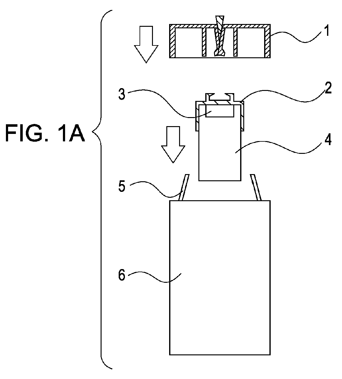
- FIGs. 1A to 1C are schematic views showing a conceptual configuration of a liquid discharging device according to an embodiment of the present invention.
- Figs. 2A and 2B are cross-sectional views showing a member for combining a device body cap and a discharging head cap with a hook.
- Figs. 3A and 3B are cross-sectional views showing another member for combining a device body cap and a discharging head cap with a hook.
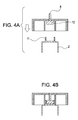
- Figs. 4A and 4B are cross-sectional views showing a further member for combining a device body cap and a discharging head cap with a magnet.
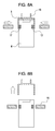
- Figs. 5A and 5B are perspective views showing discharging-head-cap fixing members using hooks.
- Figs. 6A and 6B are cross-sectional views showing the discharging-head-cap fixing members shown in Figs. 5A and 5B .
- Figs. 7A and 7B are cross-sectional views showing discharging-head-cap releasing members using hooks.
- Figs. 8A and 8B are cross-sectional views showing discharging-head-cap fixing and releasing members using magnets.
- Figs. 9A and 9B are cross-sectional views showing discharging-head-cap fixing and releasing members using inward hooks.
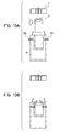
- Figs. 10A to 10E are cross-sectional views showing discharging-head-cap releasing members provided in a device body, and a series of operations thereof.
- Figs. 11A and 11B are cross-sectional views showing a liquid-discharging-cartridge fixing member provided in a device body.
- Figs. 12A to 12E are schematic views showing a state in which a liquid discharging cartridge is set in a device body after being combined with a device body cap.
- Figs. 13A to 13E are schematic views showing a first example of a structure and a series of operations for simultaneously unfixing a discharging head cap and combining a device body cap and the discharging head cap.
- Figs. 14A to 14E are schematic views showing members for unfixing the discharging head cap by changing the direction of force.
- Figs. 15A to 15D are schematic views showing a second example of a structure and a series of operations for simultaneously unfixing a discharging head cap and combining a device body cap and the discharging head cap.
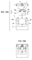
- Figs. 16A to 16D are schematic views showing a third example of a structure and a series of operations for simultaneously unfixing a discharging head cap and combining a device body cap and the discharging head cap.
- Figs. 17A to 17D are schematic views showing a fourth example of a structure and a series of operations for simultaneously unfixing a discharging head cap and combining a device body cap and the discharging head cap.
- FIGs. 1A to 1C are schematic views showing the configuration of a liquid discharging device according to an embodiment of the present invention.
- a liquid discharging device for medicine inhalation which allows medicine serving as liquid stored in a liquid discharging cartridge to be inhaled through a mouthpiece.
- a liquid discharging device includes a liquid discharging cartridge body 4 having a discharging head 3 serving as a liquid discharging portion for discharging liquid, and a discharging head cap (discharging portion cap) 2 for covering the discharging head 3.
- the discharging head cap 2 aims to protect discharging ports of the discharging head 3 so that dust will not adhere to the discharging ports and so that the surfaces of the discharging ports will not be scratched by touch, or to retain moisture so that the viscosity of liquid in the discharging ports will not change or the liquid will not dry.
- a liquid discharging device to which the present invention is applicable includes the liquid discharging cartridge, a device body 6 housing the liquid discharging cartridge, and a device body cap 1 covering the device body 6.
- the device body cap 1 is defined as a cap that is removably attached to the device body 6, that is, a cap that is detached when the device is used and is attached when the device is not used.
- the device body cap 1 covers the device body 6 to cut off the interior of the device body 6 from external air so that dust will not enter the device body 6 when the liquid discharging cartridge is not mounted.
- the device body cap 1 also covers and protects the mouthpiece 5.
- the user detaches the device body cap 1, and attaches the liquid discharging cartridge to the device body 6 ( Fig. 1A ). Then, the user attaches the device body cap 1 to the device body 6 to combine the device body cap 1 with the discharging head cap 2 ( Fig. 1B ). When the user detaches the device body cap 1 from the device body 6, the discharging head cap 2 is detached in combination with the device body cap 1 ( Fig. 1C ). Then, the user inhales the medicine while holding the mouthpiece 5 in the user's mouth.
- the mouthpiece 5 can be replaced with a nosepiece (not shown) according to the application.
- the user can inhale the medicine from the nose with the nosepiece held in the mouth.
- the liquid of the present invention is not limited to medicine, and may be liquid perfume or liquid pigment.
- a device for discharging liquid a device that generates energy for discharging pressurized gas or liquid can be adopted. While an arbitrary discharging energy generating element may be used, for example, an electrothermal transducer for applying heat energy to the liquid or an electromechanical transducer for applying mechanical energy to the liquid can be used.
- the liquid can be discharged by a method of discharging droplets of liquid from discharging ports by applying heat energy to the liquid with an electrothermal transducer (thermal jet method), a method of discharging droplets of liquid from the discharging ports by using vibratory pressure of an electromechanical transducer (e.g., a piezoelectric element) for applying mechanical energy to the liquid (piezo-jet method), or a method of discharging minute droplets of liquid by generating fine bubbles in the liquid by ultrasound and using recoil force produced when the minute bubbles burst on the liquid surface (ultrasonic mist method).
- a method of forming droplets can be arbitrary selected in accordance with the type of liquid.
- Figs. 2 , 3 , and 4 show units for combining a device body cap 1 and a discharging head cap 2.
- Figs. 2A and 2B are cross-sectional views of a first example of a combining unit.
- Fig. 2A shows a state in which the device body cap 1 and the discharging head cap 2 are not combined
- Fig. 2B shows a state in which the device body cap 1 and the discharging head cap 2 are combined.
- the discharging head cap 2 is provided with a fixed hook portion 9, and the device body cap 1 is provided with a movable hook portion 7 serving as a coupling member to be coupled to the discharging head cap 2.
- the movable cap portion 7 has a combination operating member 8 serving as a switch member for switching between states in which the device body cap 1 and the discharging head cap 2 are combined and not combined. By pushing down the combination operating member 8, the movable cap portion 7 opens outward to be coupled to the fixed hook portion 9.
- the combination operating member 8 protrudes out before the device body cap 1 and the discharging head cap 2 are combined, and is flush with or slightly recedes from the surface of the device body cap 1 after the device body cap 1 and the discharging head cap 2 are combined. This aims to prevent the user from making a human mistake of erroneously pushing the combination operating member 8 after combination.
- the combination operating member 8 incorporates a spring (not shown) such that the movable cap portion 7 is opened by pushing the combination operating member 8 once and is closed by pushing the combination operating member 8 again. This is because the discharging head cap 2 is attached again to the liquid discharging cartridge body 4 when the liquid discharging cartridge body 4 is removed.
- movable hook portion guides 7a are provided in the device body cap 1 in a manner such as to cover the fixed hook portion 9, stability is improved.
- Figs. 3A and 3B are cross-sectional views showing a second example of a unit for combining a movable hook portion and a fixed hook portion in which the movable hook portion reversely moves to close from the outer side to the inner side.
- Figs. 3A shows a state before combination
- Fig. 3B shows a state after combination.
- Figs. 4A and 4B are cross-sectional views showing a third example of a unit for combining the device body cap 1 and the discharging head cap 2 by using a magnet.
- Fig. 4A shows a state before combination
- Fig. 4B shows a state after combination.
- the discharging head cap 2 has a magnet attraction member 11.
- the device body cap 1 includes a magnet 10 serving as a coupling member for coupling to the discharging head cap 2, and a combination operating member 8 serving as a switch member. The user pushes down the combination operating member 8 so as to bring the magnet 10 into contact with the magnet attracting member 11. Fixing of Discharging Head Cap to Liquid Discharging Cartridge Body
- the discharging head cap 2 is preferably provided with a discharging-head-cap fixing member for fixing to the liquid discharging cartridge body 4.
- Figs. 5A and 5B are perspective views showing a first example of a discharging-head-cap fixing member using hooks.
- Fig. 5A shows a state in which the discharging head cap 2 is not fixed
- Fig. 5B shows a state in which the discharging head cap 2 is fixed.
- Figs. 6A and 6B are cross-sectional views, respectively, taken along line VIA-VIA of Fig. 5A and line VIB-VIB of Fig. 5B .
- the discharging head cap 2 has fixing hooks 12 serving as discharging-head-cap fixing members.
- the fixing hooks 12 are opened at apertures 14 through fixing-hook slits 13, and the discharging head cap 2 is thereby fixed to the liquid discharging cartridge body 4.
- Figs. 7A and 7B are cross-sectional views showing a member for unfixing the discharging head cap 2 from the hooks 12.
- Fig. 7A shows a state in which the discharging head cap 2 is fixed to the liquid discharging cartridge body 4, and
- Fig. 7B shows a state in which the discharging head cap 2 is unfixed.
- Figs. 8A and 8B are cross-sectional views showing a second example of a discharging-head-cap fixing member using magnets, and a releasing member therefor.
- Fig. 8A shows a state in which the discharging head cap 2 is fixed
- Fig. 8B shows a state in which the discharging head cap 2 is unfixed.
- a plurality of magnets 17 are provided in the liquid discharging cartridge body 4, and are arranged in a manner such that the same polarities are located on outer sides.
- a discharging head cap 16 including a magnet attraction member is attracted by the magnets 17 and thereby protects the surface of the discharging head 3.
- Fig. 8A shows a discharging head cap 16 including a magnet attraction member is attracted by the magnets 17 and thereby protects the surface of the discharging head 3.
- discharging-head-cap releasing magnets 18 serving as discharging-head-cap releasing members are moved closer to the magnets 17.
- Polarities on the inner sides of the discharging-head-cap releasing magnets 18 are the same as polarities on the outer sides of the magnets 17.
- the magnetic force of the magnets 17 decreases, and the attracting force of the discharging head cap 16 including the magnet attraction member decreases. This allows the discharging head cap 2 to be detached easily.
- Figs. 9A and 9B are cross-sectional views showing a third example of a discharging-head-cap fixing member using internal hooks, and a releasing member therefor.
- Fig. 9A shows a state in which the discharging head cap 2 is fixed
- Fig. 9B shows a state in which the discharging head cap 2 is unfixed.
- the device body 6 is provided with discharging-head-cap releasing members 19a having no movable portion. When the user attaches the discharging cartridge to the device body 6, the discharging-head-cap releasing members 19a push fixing hooks 12 open, so that the discharging head cap 2 is unfixed.
- the discharging head cap 2 can be detached in combination with the device body cap 1.
- Figs. 10A to 10E are cross-sectional views showing discharging-head-cap releasing members 19b for unfixing a liquid discharging cartridge body and a discharging head cap, and a series of operations.
- Fig. 10A shows a state in which a liquid discharging cartridge is placed outside a device body 6 before the discharging-head-cap releasing members 19b operate.
- Fig. 10B shows a state in which the liquid discharging cartridge is attached to the device body 6, and the discharging-head-cap releasing members 19b operate to unfix a discharging head cap 2.
- Fig. 10C shows a state in which a device body cap 1 is attached to the device body 6.
- Fig. 10D shows a state in which the device body cap 1 and the discharging head cap 2 are combined.
- Fig. 10E shows a state in which the combination of the device body cap 1 and the discharging head cap 2 is detached from the device body 6.
- the discharging-head-cap releasing members 19b protrude from the device body 6 before operation. This aims to caution the user that liquid discharging is not ready.
- the discharging head cap 2 is unfixed, as shown in Fig. 10B .
- the time at which the discharging head cap 2 is unfixed is earlier than the time at which the device body cap 1 and the discharging head cap 2 are combined. This is because, in a case in which the combining time is earlier than the unfixing time, if an attempt is made to detach the device body cap 1 without performing unfixing, load is applied to the discharging head cap 2.
- the device body 6 is electrically controlled, such failure can be avoided by using a sensor.
- Figs. 10E, 10D, 10C , 10B, and 10A are performed in that order.
- the user can properly and easily use the liquid discharging device without awareness of the discharging head cap 2 from the start of use to the end of use.
- Figs. 11A and 11B are cross-sectional views showing a liquid-discharging-cartridge fixing member 20 provided in a device body 6.
- Fig. 11A shows a state before the liquid-discharging-cartridge fixing member 20 operates.
- Fig. 11B shows a state in which the liquid-discharging-cartridge fixing member 20 operates and a liquid discharging cartridge body is fixed to the device body 6.
- the liquid-discharging-cartridge fixing member 20 aims to prevent a liquid discharging cartridge body 4 from deviating from its original position when a device body cap 1 combined with a discharging head cap 2 is detached from the device body 6. As shown in Fig.
- the liquid-discharging-cartridge fixing member 20 is operated before the device body cap 1 is attached to the device body 6.
- a portion of the liquid discharging cartridge body 4 where the leading end of the liquid-discharging-cartridge fixing member 20 abuts has a recess so as to reliably fix the liquid discharging cartridge body 4.
- operation of the liquid-discharging-cartridge fixing member 20 can be automated, similarly to the above.
- the liquid-discharging-cartridge fixing member 20 is released.
- Figs. 12A to 12E are schematic views showing states in which the liquid discharging cartridge is attached to the device body 6 after the discharging head cap 2 is combined with the liquid discharging cartridge.
- this method is easier than when the user attaches the liquid discharging cartridge to the device body 6 while holding the liquid discharging cartridge. Moreover, the user will not fall off the liquid discharging cartridge during attachment.
- Fig. 12A shows a state before the liquid discharging cartridge set in a cartridge magazine 21 is combined with the device body cap 1.
- Fig. 12B shows a state in which the liquid discharging cartridge and the device body cap 1 are combined.
- Fig. 12C shows a state in which the combination of the device body cap 1 and the liquid discharging cartridge is removed from the cartridge magazine 21.
- Fig. 12D shows a state in which the combination of the device body cap 1 and the liquid discharging cartridge is attached to the device body 6.
- Fig. 12E shows a state in which the device body cap 1 combined with the discharging head cap 2 is detached from the device body 6 after the discharging head cap 2 is unfixed.
- the time at which the discharging head cap 2 is unfixed from the liquid discharging cartridge body 4 and the time at which the device body cap 1 and the discharging head cap 2 are combined are separate. For this reason, in a case in the unfixing time is later than the combing time, when an attempt is made to detach the device body cap 1 without performing unfixing, load may be applied to the discharging head cap 2. In the fifth embodiment, this problem is avoided by simultaneously performing unfixing and combination.
- Figs. 13A to 13E are schematic views showing a structure that allows unfixing of a discharging head cap and combination of a device body cap and the discharging head cap to be performed simultaneously, and a series of operations of the structure.
- Fig. 13A is a schematic view showing a state before the device body cap and a liquid discharging cartridge are combined.
- Fig. 13B is a schematic view showing a state in which the liquid discharging cartridge is attached to the device body.
- Fig. 13C is a schematic view showing a state in which the device body cap is attached to the device body.
- Fig. 13D is a schematic view showing a state in which force conversion type discharging-head-cap releasing members 23 and a combination operating member 8 simultaneously operate.
- Fig. 13E is a schematic view showing a state in which the combination of the device body cap and the discharging head cap is detached from the device body.
- a movable hook portion 7 and a force conversion type discharging-head-cap release transmission member 22 are coupled to the combination operating member 8.
- the discharging-head-cap release transmission member 22 is also pushed down. This downward motion is converted into a horizontal motion by the force conversion type discharging-head-cap releasing members 23, thereby unfixing the discharging head cap. Examples of the discharging-head-cap releasing members 23 will be described with reference to Figs. 14A to 14E .
- Figs. 14A to 14E are schematic views showing a member for unfixing the discharging head cap by changing the direction of force.
- Fig. 14A is a schematic view showing a method using a flexible material.
- Fig. 14B is a schematic view illustrating a case in which the direction of force is changed by a pantograph method.
- Fig. 14C is a schematic view illustrating a bow method.
- Fig. 14D is a schematic view illustrating a method using a rack and a pinion.
- Fig. 14E is a schematic view illustrating an electrical method in which a rack is moved by a motor in response to power-on.
- a flexible member 24 adopted in Fig. 14A is formed by a material that originally extends straight and returns to its original straight shape even after being bent, for example, a piano wire.
- Support members 25 restrict the motion of the flexible member 24.
- a position recovery member 26, such as a spring, is provided so that the flexible member 24 returns to its original position when a downward force of the discharging-head-cap release transmission member 22 in the figure is removed.
- Fig. 14B four materials are joined at their tops like a pantograph, and members 25 for restricting the motion of the joined structure so that the joined structure extends only in the horizontal direction in the figure are provided on upper and lower sides of the joined structure. It is preferable to use a position recovery member 26, similarly to the case shown in Fig. 14A .
- Reference numerals 28 and 29 denote a vertical-direction operating member and a horizontal-direction operating member, respectively.
- a bow-shaped member 30 in which a flexible member is bent and fixed by, for example, a thread is used.
- the bow-shaped member 30 itself has a position recovery property, and therefore, a position recovery member 26 is unnecessary.
- a vertical rack 31 is coupled to a horizontal rack 32 via a pinion gear 33. Both racks are held by support members 25 so as not to be displaced during operation. In this case, it is also preferable to use a position recovery member 26, similar to Figs. 14A and 14B .
- Fig. 14E illustrates a method that is effective when the device body 6 includes an electrical member.
- a switch 34 is turned on, and a pinion gear 33 is rotated by a motor (not shown) to operate a horizontal rack 32. It is preferable to produce a program such as to stop the rotation of the motor after a predetermined time of operation or after the rack moves to a predetermined position.
- the time at which a discharging head cap 2 is unfixed from a liquid discharging cartridge body 4 and the time at which a device body cap 1 and the discharging head cap 2 are combined can be the same.
- Figs. 15A to 15D are schematic views showing the sixth embodiment.
- a liquid discharging cartridge body 4 two fixing rods 36a and 36b serving as discharging-head-cap fixing members and a fixing-rod driving motor 35 serving as a discharging-head-cap releasing member for performing unfixing by moving the fixing rods 36a and 36b are provided.
- a device body 6 includes a cartridge mounting portion 38 in which the liquid discharging cartridge body 4 is mounted, and a fixing control unit 40.
- the fixing control unit 40 sends, to the fixing-rod driving motor 35, a signal for unfixing a discharging head cap 2 by moving the fixing rods 36a and 36b.
- the discharging-head-cap fixing members and the fixing control unit are thus separately provided in the discharging liquid cartridge body 4 and the device body 6, the probability that the discharging head cap 2 will be erroneously opened at an undesirable time, for example, by hand considerably decreases. This allows the surface of the discharging head 3 to be kept clean, and is desirable from the viewpoints not only of convenience but also of hygiene during inhalation of the user.
- the user detaches the device body cap 1, and then attaches the liquid discharging cartridge to the device body 6 ( Fig. 15A ).
- the discharging head cap 2 has a fixing hook portion 9.
- a movable hook portion 7 opens outward to be combined with the fixed hook portion ( Fig. 15B ).
- a signal is sent from the fixing control unit 40 to the fixing-rod driving motor 35 via a body-side terminal 39 and a cartridge-side terminal 37.
- the fixing-rod driving motor 35 moves the fixing rods 36a and 36b toward the motor 35 on the basis of the signal, whereby the discharging head cap 2 is unfixed ( Fig. 15C ).
- the discharging head cap 2 is detached in combination with the device body cap 1 ( Figs. 15D and 15E). While the movable hook portion 7 is used as the coupling member in the sixth embodiment, the cap can be opened by magnetic force of a magnetic member.
- discharging-head-cap releasing member is provided in the liquid discharging cartridge and the fixing control unit is provided in the device body in the sixth embodiment, even when the arrangement is reversed, as shown in Figs. 16A to 16D , similar advantages can be achieved.
- a liquid discharging cartridge body 4 includes fixing rods 36a and 36b serving as discharging-head-cap fixing members, and a fixing control portion 43.
- the fixing rods 36a and 36b are formed of a magnetic material, and are respectively fixed to the liquid discharging cartridge body 4 by springs 41a and 41b.
- a device body 6 includes electromagnets 42a and 42b serving as discharging-head-cap releasing members for unfixing the fixing rods 36a and 36b formed of the magnetic material.
- the user detaches a device body cap 1, and then attaches a liquid discharging cartridge to the device body 6 ( Fig. 16A ).
- the user attaches the device body cap 1 to the device body 6 to combine the device body cap 1 with a discharging head cap 2 having a fixed hook portion 9.
- a movable hook portion 7 opens outward to be combined with the fixed hook portion 9 ( Fig. 16B ).
- a signal is sent from the fixing control unit 43 to the electromagnets 42a and 42b via a cartridge-side terminal 37 and a body-side terminal 39.
- the electromagnets 42a and 42b move the fixing rods 36a and 36b toward the device body 6 on the basis of the signal, whereby the discharging head cap 2 is unfixed ( Fig. 16C ).
- the discharging head cap 2 is detached in combination with the device body cap 1 ( Fig. 16D ).
- electromagnets are used as the discharging-head-cap releasing members in the seventh embodiment
- fixing rods formed of a non-insulating material may be moved in a non-contact manner by electrostatic force obtained by applying voltage to discharging-head-cap releasing members formed of an insulating material.
- electromagnets it is preferable to use electromagnets.
- the liquid discharging cartridge includes the discharging-head-cap releasing member 35 or the fixing control unit 43.
- a discharging-head-cap releasing member and a fixing control unit are provided in the device body and a discharging-head-cap fixing member is provided in the liquid discharging cartridge body, as shown in Figs. 17A to 17D , hygienic advantages can be obtained similarly to the above.
- the user detaches a device body cap 1, and attaches a liquid discharging cartridge to a device body 6 ( Fig. 17A ).
- the user attaches the device body cap 1 to the device body 6 to combine the device body cap 1 with a discharging head cap 2 having a fixed hook portion 9.
- a movable hook portion 7 opens outward to be combined with the fixed hook portion 9 ( Fig. 17B ).
- a signal is sent from a fixing control unit 40 to electromagnets 42a and 42b.
- the electromagnets 42a and 42b move fixing rods 36a and 36b toward the device body 6 on the basis of this signal, whereby the discharging head cap 2 is unfixed ( Fig. 17C ).
- the discharging head cap 2 is detached in combination with the device body cap 1 ( Fig. 17D ). Since the liquid discharging cartridge is replaced according to the amount of remaining liquid, it is preferable, in terms of cost, that the discharging-head-cap releasing member and the fixing control unit be provided in the device body.
- a liquid discharging device includes a device body (6) configured to house a liquid discharging cartridge body (4) having a liquid discharging portion (3) for discharge liquid, and a device body cap (1) removably attached to the device body (6).
- a discharging portion cap (2) attached to the liquid discharging cartridge body (4) so as to protect a discharging port of the liquid discharging portion (3) is detached from the liquid discharging portion (3) in combination with the device body cap (1).
Landscapes
- Health & Medical Sciences (AREA)
- Engineering & Computer Science (AREA)
- Bioinformatics & Cheminformatics (AREA)
- Pulmonology (AREA)
- Anesthesiology (AREA)
- Biomedical Technology (AREA)
- Heart & Thoracic Surgery (AREA)
- Hematology (AREA)
- Life Sciences & Earth Sciences (AREA)
- Animal Behavior & Ethology (AREA)
- General Health & Medical Sciences (AREA)
- Public Health (AREA)
- Veterinary Medicine (AREA)
- Ink Jet (AREA)
- Closures For Containers (AREA)
- Infusion, Injection, And Reservoir Apparatuses (AREA)
Abstract

Description
- The present invention relates to a liquid discharging device, a liquid discharging cartridge to be contained in the liquid discharging device, and a device body cap removably mounted on a main body of the liquid discharging device.
- Liquid discharging devices that help the user to inhale liquid medicine have been developed. The liquid-medicine discharging devices discharge the liquid medicine in the form of minute droplets into an air passage, through which air sucked via a mouthpiece flows, by utilizing the discharging principle of an inkjet method. In an example of such a liquid discharging device, a liquid discharging cartridge is replaceable. The liquid discharging cartridge basically includes a liquid discharging cartridge body and a discharging portion cap for protecting a liquid discharging portion of the liquid discharging cartridge (see Japanese Patent Laid-Open No.
2007-296384 - The present invention provides a means that allows a discharging portion cap of a liquid discharging cartridge to be detached easily.
- The present invention in its first aspect provides a liquid discharging device as specified in claims 1 to 4.
- The present invention in its second aspect provides a liquid discharging cartridge as specified in
claims 5 to 7. - The present invention in its third aspect provides a device body cap as specified in
claims - Further features of the present invention will become apparent from the following description of exemplary embodiments with reference to the attached drawings.
-
Figs. 1A to 1C are schematic views showing a conceptual configuration of a liquid discharging device according to an embodiment of the present invention. -
Figs. 2A and 2B are cross-sectional views showing a member for combining a device body cap and a discharging head cap with a hook. -
Figs. 3A and 3B are cross-sectional views showing another member for combining a device body cap and a discharging head cap with a hook. -
Figs. 4A and 4B are cross-sectional views showing a further member for combining a device body cap and a discharging head cap with a magnet. -
Figs. 5A and 5B are perspective views showing discharging-head-cap fixing members using hooks. -
Figs. 6A and 6B are cross-sectional views showing the discharging-head-cap fixing members shown inFigs. 5A and 5B . -
Figs. 7A and 7B are cross-sectional views showing discharging-head-cap releasing members using hooks. -
Figs. 8A and 8B are cross-sectional views showing discharging-head-cap fixing and releasing members using magnets. -
Figs. 9A and 9B are cross-sectional views showing discharging-head-cap fixing and releasing members using inward hooks. -
Figs. 10A to 10E are cross-sectional views showing discharging-head-cap releasing members provided in a device body, and a series of operations thereof. -
Figs. 11A and 11B are cross-sectional views showing a liquid-discharging-cartridge fixing member provided in a device body. -
Figs. 12A to 12E are schematic views showing a state in which a liquid discharging cartridge is set in a device body after being combined with a device body cap. -
Figs. 13A to 13E are schematic views showing a first example of a structure and a series of operations for simultaneously unfixing a discharging head cap and combining a device body cap and the discharging head cap. -
Figs. 14A to 14E are schematic views showing members for unfixing the discharging head cap by changing the direction of force. -
Figs. 15A to 15D are schematic views showing a second example of a structure and a series of operations for simultaneously unfixing a discharging head cap and combining a device body cap and the discharging head cap. -
Figs. 16A to 16D are schematic views showing a third example of a structure and a series of operations for simultaneously unfixing a discharging head cap and combining a device body cap and the discharging head cap. -
Figs. 17A to 17D are schematic views showing a fourth example of a structure and a series of operations for simultaneously unfixing a discharging head cap and combining a device body cap and the discharging head cap. - The present invention will be described in more detail below with reference to the drawings. In principle, like components are denoted by like reference numerals, and descriptions thereof are omitted.
-
Figs. 1A to 1C are schematic views showing the configuration of a liquid discharging device according to an embodiment of the present invention. In this embodiment, a description will be given of a liquid discharging device for medicine inhalation, which allows medicine serving as liquid stored in a liquid discharging cartridge to be inhaled through a mouthpiece. A liquid discharging device includes a liquid dischargingcartridge body 4 having a discharginghead 3 serving as a liquid discharging portion for discharging liquid, and a discharging head cap (discharging portion cap) 2 for covering thedischarging head 3. Thedischarging head cap 2 aims to protect discharging ports of thedischarging head 3 so that dust will not adhere to the discharging ports and so that the surfaces of the discharging ports will not be scratched by touch, or to retain moisture so that the viscosity of liquid in the discharging ports will not change or the liquid will not dry. A liquid discharging device to which the present invention is applicable includes the liquid discharging cartridge, adevice body 6 housing the liquid discharging cartridge, and a device body cap 1 covering thedevice body 6. - In the present invention, the device body cap 1 is defined as a cap that is removably attached to the
device body 6, that is, a cap that is detached when the device is used and is attached when the device is not used. Preferably, the device body cap 1 covers thedevice body 6 to cut off the interior of thedevice body 6 from external air so that dust will not enter thedevice body 6 when the liquid discharging cartridge is not mounted. Further preferably, when amouthpiece 5 is attached to thedevice body 6, the device body cap 1 also covers and protects themouthpiece 5. - When using the liquid discharging device, the user detaches the device body cap 1, and attaches the liquid discharging cartridge to the device body 6 (
Fig. 1A ). Then, the user attaches the device body cap 1 to thedevice body 6 to combine the device body cap 1 with the discharging head cap 2 (Fig. 1B ). When the user detaches the device body cap 1 from thedevice body 6, the discharginghead cap 2 is detached in combination with the device body cap 1 (Fig. 1C ). Then, the user inhales the medicine while holding themouthpiece 5 in the user's mouth. - The
mouthpiece 5 can be replaced with a nosepiece (not shown) according to the application. The user can inhale the medicine from the nose with the nosepiece held in the mouth. - While medicine is used as the liquid in the embodiment, the liquid of the present invention is not limited to medicine, and may be liquid perfume or liquid pigment.
- As a device for discharging liquid, a device that generates energy for discharging pressurized gas or liquid can be adopted. While an arbitrary discharging energy generating element may be used, for example, an electrothermal transducer for applying heat energy to the liquid or an electromechanical transducer for applying mechanical energy to the liquid can be used. That is, for example, the liquid can be discharged by a method of discharging droplets of liquid from discharging ports by applying heat energy to the liquid with an electrothermal transducer (thermal jet method), a method of discharging droplets of liquid from the discharging ports by using vibratory pressure of an electromechanical transducer (e.g., a piezoelectric element) for applying mechanical energy to the liquid (piezo-jet method), or a method of discharging minute droplets of liquid by generating fine bubbles in the liquid by ultrasound and using recoil force produced when the minute bubbles burst on the liquid surface (ultrasonic mist method). A method of forming droplets can be arbitrary selected in accordance with the type of liquid.
- When a thermal jet method is used, it is possible, in each discharging head, to increase the bore diameter of the discharging ports, the amount of pulse heat energy used for discharging, size accuracy of mircoheaters serving as electrothermal transducer, and reproducibility. For this reason, a narrow droplet diameter distribution can be achieved. Further, since the production cost of the head is low, the thermal jet method is highly applicable to small devices in which the head needs to be frequently replaced. Hence, it is particularly preferable to adopt the discharging principle of the thermal jet method in an application to a liquid discharging device that requires portability and convenience.
-
Figs. 2 ,3 , and4 show units for combining a device body cap 1 and a discharginghead cap 2.Figs. 2A and 2B are cross-sectional views of a first example of a combining unit.Fig. 2A shows a state in which the device body cap 1 and the discharginghead cap 2 are not combined, andFig. 2B shows a state in which the device body cap 1 and the discharginghead cap 2 are combined. The discharginghead cap 2 is provided with a fixedhook portion 9, and the device body cap 1 is provided with amovable hook portion 7 serving as a coupling member to be coupled to the discharginghead cap 2. Themovable cap portion 7 has acombination operating member 8 serving as a switch member for switching between states in which the device body cap 1 and the discharginghead cap 2 are combined and not combined. By pushing down thecombination operating member 8, themovable cap portion 7 opens outward to be coupled to the fixedhook portion 9. - Preferably, the
combination operating member 8 protrudes out before the device body cap 1 and the discharginghead cap 2 are combined, and is flush with or slightly recedes from the surface of the device body cap 1 after the device body cap 1 and the discharginghead cap 2 are combined. This aims to prevent the user from making a human mistake of erroneously pushing thecombination operating member 8 after combination. Preferably, like a knock-type ballpoint pen, thecombination operating member 8 incorporates a spring (not shown) such that themovable cap portion 7 is opened by pushing thecombination operating member 8 once and is closed by pushing thecombination operating member 8 again. This is because the discharginghead cap 2 is attached again to the liquid dischargingcartridge body 4 when the liquid dischargingcartridge body 4 is removed. When movable hook portion guides 7a are provided in the device body cap 1 in a manner such as to cover the fixedhook portion 9, stability is improved. -
Figs. 3A and 3B are cross-sectional views showing a second example of a unit for combining a movable hook portion and a fixed hook portion in which the movable hook portion reversely moves to close from the outer side to the inner side.Figs. 3A shows a state before combination, andFig. 3B shows a state after combination. -
Figs. 4A and 4B are cross-sectional views showing a third example of a unit for combining the device body cap 1 and the discharginghead cap 2 by using a magnet.Fig. 4A shows a state before combination, andFig. 4B shows a state after combination. The discharginghead cap 2 has amagnet attraction member 11. The device body cap 1 includes amagnet 10 serving as a coupling member for coupling to the discharginghead cap 2, and acombination operating member 8 serving as a switch member. The user pushes down thecombination operating member 8 so as to bring themagnet 10 into contact with themagnet attracting member 11. Fixing of Discharging Head Cap to Liquid Discharging Cartridge Body - To prevent the user from erroneously removing a discharging
head cap 2 from a liquid dischargingcartridge body 4, the discharginghead cap 2 is preferably provided with a discharging-head-cap fixing member for fixing to the liquid dischargingcartridge body 4. -
Figs. 5A and 5B are perspective views showing a first example of a discharging-head-cap fixing member using hooks.Fig. 5A shows a state in which the discharginghead cap 2 is not fixed, andFig. 5B shows a state in which the discharginghead cap 2 is fixed. -
Figs. 6A and 6B are cross-sectional views, respectively, taken along line VIA-VIA ofFig. 5A and line VIB-VIB ofFig. 5B . The discharginghead cap 2 has fixinghooks 12 serving as discharging-head-cap fixing members. The fixing hooks 12 are opened atapertures 14 through fixing-hook slits 13, and the discharginghead cap 2 is thereby fixed to the liquid dischargingcartridge body 4. To prevent the user from erroneously removing the discharginghead cap 2 from the liquid dischargingcartridge body 4, it is preferable to form a plurality of (two inFigs. 5A and 5B ) fixing hooks 12. -
Figs. 7A and 7B are cross-sectional views showing a member for unfixing the discharginghead cap 2 from thehooks 12.Fig. 7A shows a state in which the discharginghead cap 2 is fixed to the liquid dischargingcartridge body 4, andFig. 7B shows a state in which the discharginghead cap 2 is unfixed. - By pushing a
hook releasing member 15 serving as a discharging-head-cap releasing member for unfixing the discharginghead cap 2 from the liquid dischargingcartridge body 4 into the liquid dischargingcartridge body 4, the fixing hooks 12 are compressed into the fixing-hook slits 13, whereby the discharginghead cap 2 is unfixed. -
Figs. 8A and 8B are cross-sectional views showing a second example of a discharging-head-cap fixing member using magnets, and a releasing member therefor.Fig. 8A shows a state in which the discharginghead cap 2 is fixed, andFig. 8B shows a state in which the discharginghead cap 2 is unfixed. A plurality ofmagnets 17 are provided in the liquid dischargingcartridge body 4, and are arranged in a manner such that the same polarities are located on outer sides. As shown inFig. 8A , a discharginghead cap 16 including a magnet attraction member is attracted by themagnets 17 and thereby protects the surface of the discharginghead 3. To unfix the discharginghead cap 16, as shown inFig. 8B , discharging-head-cap releasing magnets 18 serving as discharging-head-cap releasing members are moved closer to themagnets 17. Polarities on the inner sides of the discharging-head-cap releasing magnets 18 are the same as polarities on the outer sides of themagnets 17. When the same polarities come closer to each other, the magnetic force of themagnets 17 decreases, and the attracting force of the discharginghead cap 16 including the magnet attraction member decreases. This allows the discharginghead cap 2 to be detached easily. -
Figs. 9A and 9B are cross-sectional views showing a third example of a discharging-head-cap fixing member using internal hooks, and a releasing member therefor.Fig. 9A shows a state in which the discharginghead cap 2 is fixed, andFig. 9B shows a state in which the discharginghead cap 2 is unfixed. Thedevice body 6 is provided with discharging-head-cap releasing members 19a having no movable portion. When the user attaches the discharging cartridge to thedevice body 6, the discharging-head-cap releasing members 19a push fixing hooks 12 open, so that the discharginghead cap 2 is unfixed. When the user attaches the device body cap 1 to thedevice body 6 in this state so as to operate the combination operating member (switch member for switching between a state in which the device body cap 1 and the discharginghead cap 2 are coupled and a state in which the caps are not coupled), the discharginghead cap 2 can be detached in combination with the device body cap 1. -
Figs. 10A to 10E are cross-sectional views showing discharging-head-cap releasing members 19b for unfixing a liquid discharging cartridge body and a discharging head cap, and a series of operations.Fig. 10A shows a state in which a liquid discharging cartridge is placed outside adevice body 6 before the discharging-head-cap releasing members 19b operate.Fig. 10B shows a state in which the liquid discharging cartridge is attached to thedevice body 6, and the discharging-head-cap releasing members 19b operate to unfix a discharginghead cap 2.Fig. 10C shows a state in which a device body cap 1 is attached to thedevice body 6.Fig. 10D shows a state in which the device body cap 1 and the discharginghead cap 2 are combined.Fig. 10E shows a state in which the combination of the device body cap 1 and the discharginghead cap 2 is detached from thedevice body 6. - As shown in
Fig. 10A , the discharging-head-cap releasing members 19b protrude from thedevice body 6 before operation. This aims to caution the user that liquid discharging is not ready. By pushing the discharging-head-cap releasing members 19b after attaching the liquid discharging cartridge, the discharginghead cap 2 is unfixed, as shown inFig. 10B . - Preferably, the time at which the discharging
head cap 2 is unfixed is earlier than the time at which the device body cap 1 and the discharginghead cap 2 are combined. This is because, in a case in which the combining time is earlier than the unfixing time, if an attempt is made to detach the device body cap 1 without performing unfixing, load is applied to the discharginghead cap 2. When thedevice body 6 is electrically controlled, such failure can be avoided by using a sensor. Alternatively, after a series of operations are sequentially performed and the device body cap 1 becomes ready to be detached, this state may be indicated to the user with sound and light. Further alternatively, it is possible to produce a program that permits liquid discharging when a sensor detects that the discharginghead cap 2 has been separated from the discharginghead 3. - To remove the liquid discharging cartridge from the
device body 6 after use, the steps shown inFigs. 10E, 10D, 10C ,10B, and 10A are performed in that order. In this case, the user can properly and easily use the liquid discharging device without awareness of the discharginghead cap 2 from the start of use to the end of use. -
Figs. 11A and 11B are cross-sectional views showing a liquid-discharging-cartridge fixing member 20 provided in adevice body 6.Fig. 11A shows a state before the liquid-discharging-cartridge fixing member 20 operates.Fig. 11B shows a state in which the liquid-discharging-cartridge fixing member 20 operates and a liquid discharging cartridge body is fixed to thedevice body 6. The liquid-discharging-cartridge fixing member 20 aims to prevent a liquid dischargingcartridge body 4 from deviating from its original position when a device body cap 1 combined with a discharginghead cap 2 is detached from thedevice body 6. As shown inFig. 11B , the liquid-discharging-cartridge fixing member 20 is operated before the device body cap 1 is attached to thedevice body 6. Preferably, a portion of the liquid dischargingcartridge body 4 where the leading end of the liquid-discharging-cartridge fixing member 20 abuts has a recess so as to reliably fix the liquid dischargingcartridge body 4. When thedevice body 6 is electrically controlled, operation of the liquid-discharging-cartridge fixing member 20 can be automated, similarly to the above. - To remove the liquid discharging cartridge from the
device body 6 after use, the liquid-discharging-cartridge fixing member 20 is released. -
Figs. 12A to 12E are schematic views showing states in which the liquid discharging cartridge is attached to thedevice body 6 after the discharginghead cap 2 is combined with the liquid discharging cartridge. When the user is an elderly person or a child, this method is easier than when the user attaches the liquid discharging cartridge to thedevice body 6 while holding the liquid discharging cartridge. Moreover, the user will not fall off the liquid discharging cartridge during attachment. -
Fig. 12A shows a state before the liquid discharging cartridge set in acartridge magazine 21 is combined with the device body cap 1.Fig. 12B shows a state in which the liquid discharging cartridge and the device body cap 1 are combined.Fig. 12C shows a state in which the combination of the device body cap 1 and the liquid discharging cartridge is removed from thecartridge magazine 21.Fig. 12D shows a state in which the combination of the device body cap 1 and the liquid discharging cartridge is attached to thedevice body 6.Fig. 12E shows a state in which the device body cap 1 combined with the discharginghead cap 2 is detached from thedevice body 6 after the discharginghead cap 2 is unfixed. - As described above, it is necessary to be careful not to remove the device body cap 1 combined with the discharging
head cap 2 from thedevice body 6 before the discharging-head-cap releasing members 19b operate. - In the third and fourth embodiments, the time at which the discharging
head cap 2 is unfixed from the liquid dischargingcartridge body 4 and the time at which the device body cap 1 and the discharginghead cap 2 are combined are separate. For this reason, in a case in the unfixing time is later than the combing time, when an attempt is made to detach the device body cap 1 without performing unfixing, load may be applied to the discharginghead cap 2. In the fifth embodiment, this problem is avoided by simultaneously performing unfixing and combination. -
Figs. 13A to 13E are schematic views showing a structure that allows unfixing of a discharging head cap and combination of a device body cap and the discharging head cap to be performed simultaneously, and a series of operations of the structure.Fig. 13A is a schematic view showing a state before the device body cap and a liquid discharging cartridge are combined.Fig. 13B is a schematic view showing a state in which the liquid discharging cartridge is attached to the device body.Fig. 13C is a schematic view showing a state in which the device body cap is attached to the device body.Fig. 13D is a schematic view showing a state in which force conversion type discharging-head-cap releasing members 23 and acombination operating member 8 simultaneously operate.Fig. 13E is a schematic view showing a state in which the combination of the device body cap and the discharging head cap is detached from the device body. - In the fifth embodiment, a
movable hook portion 7 and a force conversion type discharging-head-caprelease transmission member 22 are coupled to thecombination operating member 8. When the user pushes down thecombination operating member 8, the discharging-head-caprelease transmission member 22 is also pushed down. This downward motion is converted into a horizontal motion by the force conversion type discharging-head-cap releasing members 23, thereby unfixing the discharging head cap. Examples of the discharging-head-cap releasing members 23 will be described with reference toFigs. 14A to 14E . -
Figs. 14A to 14E are schematic views showing a member for unfixing the discharging head cap by changing the direction of force.Fig. 14A is a schematic view showing a method using a flexible material.Fig. 14B is a schematic view illustrating a case in which the direction of force is changed by a pantograph method.Fig. 14C is a schematic view illustrating a bow method.Fig. 14D is a schematic view illustrating a method using a rack and a pinion.Fig. 14E is a schematic view illustrating an electrical method in which a rack is moved by a motor in response to power-on. - Preferably, a
flexible member 24 adopted inFig. 14A is formed by a material that originally extends straight and returns to its original straight shape even after being bent, for example, a piano wire.Support members 25 restrict the motion of theflexible member 24. Preferably, aposition recovery member 26, such as a spring, is provided so that theflexible member 24 returns to its original position when a downward force of the discharging-head-caprelease transmission member 22 in the figure is removed. - In
Fig. 14B , four materials are joined at their tops like a pantograph, andmembers 25 for restricting the motion of the joined structure so that the joined structure extends only in the horizontal direction in the figure are provided on upper and lower sides of the joined structure. It is preferable to use aposition recovery member 26, similarly to the case shown inFig. 14A .Reference numerals - In
Fig. 14C , a bow-shapedmember 30 in which a flexible member is bent and fixed by, for example, a thread is used. In this case, the bow-shapedmember 30 itself has a position recovery property, and therefore, aposition recovery member 26 is unnecessary. - In
Fig. 14D , a vertical rack 31 is coupled to ahorizontal rack 32 via apinion gear 33. Both racks are held bysupport members 25 so as not to be displaced during operation. In this case, it is also preferable to use aposition recovery member 26, similar toFigs. 14A and 14B . -
Fig. 14E illustrates a method that is effective when thedevice body 6 includes an electrical member. When the above-described discharging-head-caprelease transmission member 22 is pushed down, aswitch 34 is turned on, and apinion gear 33 is rotated by a motor (not shown) to operate ahorizontal rack 32. It is preferable to produce a program such as to stop the rotation of the motor after a predetermined time of operation or after the rack moves to a predetermined position. - In the sixth embodiment, similarly to the fifth embodiment, the time at which a discharging
head cap 2 is unfixed from a liquid dischargingcartridge body 4 and the time at which a device body cap 1 and the discharginghead cap 2 are combined can be the same. -
Figs. 15A to 15D are schematic views showing the sixth embodiment. In a liquid dischargingcartridge body 4, two fixingrods rod driving motor 35 serving as a discharging-head-cap releasing member for performing unfixing by moving the fixingrods device body 6 includes acartridge mounting portion 38 in which the liquid dischargingcartridge body 4 is mounted, and a fixingcontrol unit 40. The fixingcontrol unit 40 sends, to the fixing-rod driving motor 35, a signal for unfixing a discharginghead cap 2 by moving the fixingrods - Since the discharging-head-cap fixing members and the fixing control unit are thus separately provided in the discharging
liquid cartridge body 4 and thedevice body 6, the probability that the discharginghead cap 2 will be erroneously opened at an undesirable time, for example, by hand considerably decreases. This allows the surface of the discharginghead 3 to be kept clean, and is desirable from the viewpoints not only of convenience but also of hygiene during inhalation of the user. - To use the liquid discharging device of the embodiment, the user detaches the device body cap 1, and then attaches the liquid discharging cartridge to the device body 6 (
Fig. 15A ). - Subsequently, the user attaches the device body cap 1 to the
device body 6 to combine the device body cap 1 with the discharginghead cap 2. The discharginghead cap 2 has a fixinghook portion 9. By pushing down acombination operating member 8 of the device body cap 1, amovable hook portion 7 opens outward to be combined with the fixed hook portion (Fig. 15B ). - Before the user discharges the liquid, a signal is sent from the fixing
control unit 40 to the fixing-rod driving motor 35 via a body-side terminal 39 and a cartridge-side terminal 37. The fixing-rod driving motor 35 moves the fixingrods motor 35 on the basis of the signal, whereby the discharginghead cap 2 is unfixed (Fig. 15C ). - When the user detaches the device body cap 1 from the
device body 6, the discharginghead cap 2 is detached in combination with the device body cap 1 (Figs. 15D and 15E). While themovable hook portion 7 is used as the coupling member in the sixth embodiment, the cap can be opened by magnetic force of a magnetic member. - While the discharging-head-cap releasing member is provided in the liquid discharging cartridge and the fixing control unit is provided in the device body in the sixth embodiment, even when the arrangement is reversed, as shown in
Figs. 16A to 16D , similar advantages can be achieved. - A liquid discharging
cartridge body 4 includes fixingrods control portion 43. The fixingrods cartridge body 4 bysprings device body 6 includeselectromagnets rods - To use the liquid discharging device of the embodiment, the user detaches a device body cap 1, and then attaches a liquid discharging cartridge to the device body 6 (
Fig. 16A ). - Subsequently, the user attaches the device body cap 1 to the
device body 6 to combine the device body cap 1 with a discharginghead cap 2 having a fixedhook portion 9. By pushing down acombination operating member 8 of the device body cap 1, amovable hook portion 7 opens outward to be combined with the fixed hook portion 9 (Fig. 16B ). - Before the user discharges liquid, a signal is sent from the fixing
control unit 43 to theelectromagnets side terminal 37 and a body-side terminal 39. Theelectromagnets rods device body 6 on the basis of the signal, whereby the discharginghead cap 2 is unfixed (Fig. 16C ). - When the user detaches the device body cap 1 from the
device body 6, the discharginghead cap 2 is detached in combination with the device body cap 1 (Fig. 16D ). - While the electromagnets are used as the discharging-head-cap releasing members in the seventh embodiment, fixing rods formed of a non-insulating material may be moved in a non-contact manner by electrostatic force obtained by applying voltage to discharging-head-cap releasing members formed of an insulating material. However, from the viewpoint of the volume of force to be generated, it is preferable to use electromagnets.
- In the sixth and seventh embodiments, the liquid discharging cartridge includes the discharging-head-
cap releasing member 35 or the fixingcontrol unit 43. Alternatively, when a discharging-head-cap releasing member and a fixing control unit are provided in the device body and a discharging-head-cap fixing member is provided in the liquid discharging cartridge body, as shown inFigs. 17A to 17D , hygienic advantages can be obtained similarly to the above. - To use the liquid discharging device of the embodiment, the user detaches a device body cap 1, and attaches a liquid discharging cartridge to a device body 6 (
Fig. 17A ). - Subsequently, the user attaches the device body cap 1 to the
device body 6 to combine the device body cap 1 with a discharginghead cap 2 having a fixedhook portion 9. By pushing down acombination operating member 8 of the device body cap 1, amovable hook portion 7 opens outward to be combined with the fixed hook portion 9 (Fig. 17B ). - Before the user discharges liquid, a signal is sent from a fixing
control unit 40 toelectromagnets electromagnets move fixing rods device body 6 on the basis of this signal, whereby the discharginghead cap 2 is unfixed (Fig. 17C ). - When the user detaches the device body cap 1 from the
device body 6, the discharginghead cap 2 is detached in combination with the device body cap 1 (Fig. 17D ). Since the liquid discharging cartridge is replaced according to the amount of remaining liquid, it is preferable, in terms of cost, that the discharging-head-cap releasing member and the fixing control unit be provided in the device body. - While the present invention has been described with reference to exemplary embodiments, it is to be understood that the invention is not limited to the disclosed exemplary embodiments. The scope of the following claims is to be accorded the broadest interpretation so as to encompass all modifications, equivalent structures and functions.
A liquid discharging device includes a device body (6) configured to house a liquid discharging cartridge body (4) having a liquid discharging portion (3) for discharge liquid, and a device body cap (1) removably attached to the device body (6). When the device body cap (1) is detached from the device body (6), a discharging portion cap (2) attached to the liquid discharging cartridge body (4) so as to protect a discharging port of the liquid discharging portion (3) is detached from the liquid discharging portion (3) in combination with the device body cap (1).
Claims (9)
- A liquid discharging device comprising:a device body (6) configured to house a liquid discharging cartridge body (4) having a liquid discharging portion (3) that discharges liquid;a device body cap (1) removably attached to the device body (6); andcoupling means (7) configured to couple the device body cap (1) to a discharging portion cap (2) attached to the liquid discharging cartridge body (4) so as to protect a discharging port of the liquid discharging portion (3),wherein the coupling means (7) causes the discharging portion cap (2) to be detached from the liquid discharging portion (3) when the device body cap (1) is detached from the device body (6).
- The liquid discharging device according to claim 1, further comprising:switch means configured to switch the coupling means between a coupled state in which the device body cap and the discharging portion cap are coupled and an uncoupled state in which the device body cap and the discharging portion cap are not coupled.
- The liquid discharging device according to claim 1 or 2, further comprising:fixing means configured to fix the discharging portion cap to the liquid discharging cartridge body.
- The liquid discharging device according to claim 3, further comprising:control means configured to release fixing of the discharging portion cap and the liquid discharging cartridge body by the fixing means.
- A liquid discharging cartridge comprising:a liquid discharging portion (3) configured to discharge liquid; anda discharging portion cap (2) configured to protect a discharging port of the liquid discharging portion (3),wherein the discharging portion cap (2) includes coupling means (7) to be coupled to a device body cap (1) provided in a device body (6) of a liquid discharging device that houses the liquid discharging cartridge, andwherein the coupling means (7) causes the discharging portion cap (2) to be detached from the liquid discharging portion (3) when the device body cap (1) is detached from the device body (6).
- The liquid discharging cartridge according to claim 5, further comprising:switch means configured to switch the coupling member between a coupled state in which the device body cap and the discharging portion cap are coupled and an uncoupled state in which the device body cap and the discharging portion cap are not coupled.
- The liquid discharging cartridge according to claim 5 or 6, further comprising:fixing means configured to fix the discharging portion cap to the liquid discharging cartridge.
- A device body cap (1) removably attached to a device body (6) of a liquid discharging device that houses a liquid discharging cartridge body (4) having a liquid discharging portion (3) for discharging liquid, the device body cap comprising:coupling means (7) to be coupled to a discharging portion cap (2) provided in the liquid discharging cartridge body (4) so as to protect a discharging port of the liquid discharging portion (3), andwherein the coupling means (7) causes the discharging portion cap (2) to be detached from the liquid discharging portion (3) when the device body cap (1) is detached from the device body (6).
- The device body cap according to claim 8, further comprising:switch means configured to switch the coupling means between a coupled state in which the device body cap and the discharging portion cap are coupled and an uncoupled state in which the device body cap and the discharging portion cap are not coupled.
Applications Claiming Priority (1)
| Application Number | Priority Date | Filing Date | Title |
|---|---|---|---|
| JP2008286729A JP5574596B2 (en) | 2008-11-07 | 2008-11-07 | Liquid discharge device, liquid discharge cartridge, and cap for device main body |
Publications (2)
| Publication Number | Publication Date |
|---|---|
| EP2184170A1 true EP2184170A1 (en) | 2010-05-12 |
| EP2184170B1 EP2184170B1 (en) | 2011-06-15 |
Family
ID=41429467
Family Applications (1)
| Application Number | Title | Priority Date | Filing Date |
|---|---|---|---|
| EP09173261A Active EP2184170B1 (en) | 2008-11-07 | 2009-10-16 | Liquid discharging device, liquid discharging cartridge, and device body cap |
Country Status (5)
| Country | Link |
|---|---|
| US (1) | US8662361B2 (en) |
| EP (1) | EP2184170B1 (en) |
| JP (1) | JP5574596B2 (en) |
| CN (1) | CN101732786A (en) |
| AT (1) | ATE512799T1 (en) |
Citations (4)
| Publication number | Priority date | Publication date | Assignee | Title |
|---|---|---|---|---|
| EP0861732A2 (en) * | 1997-02-14 | 1998-09-02 | Canon Kabushiki Kaisha | Ink-jet cartridge and method of storing print head |
| JP2001277529A (en) * | 2000-04-04 | 2001-10-09 | Funai Electric Co Ltd | Printer |
| WO2003068513A1 (en) * | 2002-02-13 | 2003-08-21 | Silverbrook Research Pty. Ltd. | Printer with capping device |
| JP2007296384A (en) | 2003-03-19 | 2007-11-15 | Canon Inc | Drug delivery device |
Family Cites Families (1)
| Publication number | Priority date | Publication date | Assignee | Title |
|---|---|---|---|---|
| US4185756A (en) * | 1977-11-28 | 1980-01-29 | American Flange & Manufacturing Co. | Dispensing package and method |
-
2008
- 2008-11-07 JP JP2008286729A patent/JP5574596B2/en not_active Expired - Fee Related
-
2009
- 2009-10-16 EP EP09173261A patent/EP2184170B1/en active Active
- 2009-10-16 AT AT09173261T patent/ATE512799T1/en not_active IP Right Cessation
- 2009-11-05 US US12/613,447 patent/US8662361B2/en not_active Expired - Fee Related
- 2009-11-06 CN CN200910212034A patent/CN101732786A/en active Pending
Patent Citations (4)
| Publication number | Priority date | Publication date | Assignee | Title |
|---|---|---|---|---|
| EP0861732A2 (en) * | 1997-02-14 | 1998-09-02 | Canon Kabushiki Kaisha | Ink-jet cartridge and method of storing print head |
| JP2001277529A (en) * | 2000-04-04 | 2001-10-09 | Funai Electric Co Ltd | Printer |
| WO2003068513A1 (en) * | 2002-02-13 | 2003-08-21 | Silverbrook Research Pty. Ltd. | Printer with capping device |
| JP2007296384A (en) | 2003-03-19 | 2007-11-15 | Canon Inc | Drug delivery device |
Also Published As
| Publication number | Publication date |
|---|---|
| US8662361B2 (en) | 2014-03-04 |
| EP2184170B1 (en) | 2011-06-15 |
| JP5574596B2 (en) | 2014-08-20 |
| JP2010110509A (en) | 2010-05-20 |
| ATE512799T1 (en) | 2011-07-15 |
| CN101732786A (en) | 2010-06-16 |
| US20100116269A1 (en) | 2010-05-13 |
Similar Documents
| Publication | Publication Date | Title |
|---|---|---|
| JP5328256B2 (en) | Inhaler | |
| JP4393518B2 (en) | Chemical cartridge and inhaler using the cartridge | |
| EP2381878B1 (en) | Non-pressurized system for creating liquid droplets in a dental cleaning appliance | |
| US20130319404A1 (en) | Liquid Droplet Spray Device | |
| CN101642594B (en) | Inhaler | |
| JP5252890B2 (en) | Drug delivery device | |
| HK1250133A1 (en) | Non-combustion-type flavor inhaler | |
| JP2009213618A (en) | Non-discharge liquid cartridge and liquid agent discharger | |
| EP3243766B1 (en) | Package for accommodating products | |
| CN101918059A (en) | Drug ejecting apparatus and control method thereof | |
| US11712061B2 (en) | Electronic cigarette carrier | |
| EP2184170B1 (en) | Liquid discharging device, liquid discharging cartridge, and device body cap | |
| EP4037509B1 (en) | Aerosol generation device | |
| US8602022B2 (en) | Medicine ejection device and control method therefor | |
| JP2004350971A (en) | Droplet ejection device | |
| DE60040667D1 (en) | THERMALLY BENDING ACTUATOR FOR A MICROELECTROMECHANICAL CONSTRUCTION ELEMENT | |
| WO2008010425A1 (en) | Medicine ejection device | |
| JP4498191B2 (en) | Droplet discharge device | |
| JP2009247467A (en) | Pharmaceutical inhaler | |
| JP2005305708A (en) | Ink jet recording apparatus and ink supply method thereof |
Legal Events
| Date | Code | Title | Description |
|---|---|---|---|
| PUAI | Public reference made under article 153(3) epc to a published international application that has entered the european phase |
Free format text: ORIGINAL CODE: 0009012 |
|
| AK | Designated contracting states |
Kind code of ref document: A1 Designated state(s): AT BE BG CH CY CZ DE DK EE ES FI FR GB GR HR HU IE IS IT LI LT LU LV MC MK MT NL NO PL PT RO SE SI SK SM TR |
|
| AX | Request for extension of the european patent |
Extension state: AL BA RS |
|
| GRAP | Despatch of communication of intention to grant a patent |
Free format text: ORIGINAL CODE: EPIDOSNIGR1 |
|
| 17P | Request for examination filed |
Effective date: 20101112 |
|
| GRAS | Grant fee paid |
Free format text: ORIGINAL CODE: EPIDOSNIGR3 |
|
| GRAA | (expected) grant |
Free format text: ORIGINAL CODE: 0009210 |
|
| AK | Designated contracting states |
Kind code of ref document: B1 Designated state(s): AT BE BG CH CY CZ DE DK EE ES FI FR GB GR HR HU IE IS IT LI LT LU LV MC MK MT NL NO PL PT RO SE SI SK SM TR |
|
| REG | Reference to a national code |
Ref country code: GB Ref legal event code: FG4D Ref country code: CH Ref legal event code: EP |
|
| REG | Reference to a national code |
Ref country code: IE Ref legal event code: FG4D |
|
| REG | Reference to a national code |
Ref country code: DE Ref legal event code: R096 Ref document number: 602009001543 Country of ref document: DE Effective date: 20110728 |
|
| REG | Reference to a national code |
Ref country code: NL Ref legal event code: VDEP Effective date: 20110615 |
|
| PG25 | Lapsed in a contracting state [announced via postgrant information from national office to epo] |
Ref country code: LT Free format text: LAPSE BECAUSE OF FAILURE TO SUBMIT A TRANSLATION OF THE DESCRIPTION OR TO PAY THE FEE WITHIN THE PRESCRIBED TIME-LIMIT Effective date: 20110615 Ref country code: SE Free format text: LAPSE BECAUSE OF FAILURE TO SUBMIT A TRANSLATION OF THE DESCRIPTION OR TO PAY THE FEE WITHIN THE PRESCRIBED TIME-LIMIT Effective date: 20110615 Ref country code: NO Free format text: LAPSE BECAUSE OF FAILURE TO SUBMIT A TRANSLATION OF THE DESCRIPTION OR TO PAY THE FEE WITHIN THE PRESCRIBED TIME-LIMIT Effective date: 20110915 Ref country code: HR Free format text: LAPSE BECAUSE OF FAILURE TO SUBMIT A TRANSLATION OF THE DESCRIPTION OR TO PAY THE FEE WITHIN THE PRESCRIBED TIME-LIMIT Effective date: 20110615 |
|
| PG25 | Lapsed in a contracting state [announced via postgrant information from national office to epo] |
Ref country code: GR Free format text: LAPSE BECAUSE OF FAILURE TO SUBMIT A TRANSLATION OF THE DESCRIPTION OR TO PAY THE FEE WITHIN THE PRESCRIBED TIME-LIMIT Effective date: 20110916 Ref country code: AT Free format text: LAPSE BECAUSE OF FAILURE TO SUBMIT A TRANSLATION OF THE DESCRIPTION OR TO PAY THE FEE WITHIN THE PRESCRIBED TIME-LIMIT Effective date: 20110615 Ref country code: FI Free format text: LAPSE BECAUSE OF FAILURE TO SUBMIT A TRANSLATION OF THE DESCRIPTION OR TO PAY THE FEE WITHIN THE PRESCRIBED TIME-LIMIT Effective date: 20110615 Ref country code: CY Free format text: LAPSE BECAUSE OF FAILURE TO SUBMIT A TRANSLATION OF THE DESCRIPTION OR TO PAY THE FEE WITHIN THE PRESCRIBED TIME-LIMIT Effective date: 20110615 Ref country code: LV Free format text: LAPSE BECAUSE OF FAILURE TO SUBMIT A TRANSLATION OF THE DESCRIPTION OR TO PAY THE FEE WITHIN THE PRESCRIBED TIME-LIMIT Effective date: 20110615 Ref country code: SI Free format text: LAPSE BECAUSE OF FAILURE TO SUBMIT A TRANSLATION OF THE DESCRIPTION OR TO PAY THE FEE WITHIN THE PRESCRIBED TIME-LIMIT Effective date: 20110615 |
|
| PG25 | Lapsed in a contracting state [announced via postgrant information from national office to epo] |
Ref country code: NL Free format text: LAPSE BECAUSE OF FAILURE TO SUBMIT A TRANSLATION OF THE DESCRIPTION OR TO PAY THE FEE WITHIN THE PRESCRIBED TIME-LIMIT Effective date: 20110615 Ref country code: BE Free format text: LAPSE BECAUSE OF FAILURE TO SUBMIT A TRANSLATION OF THE DESCRIPTION OR TO PAY THE FEE WITHIN THE PRESCRIBED TIME-LIMIT Effective date: 20110615 |
|
| PG25 | Lapsed in a contracting state [announced via postgrant information from national office to epo] |
Ref country code: PT Free format text: LAPSE BECAUSE OF FAILURE TO SUBMIT A TRANSLATION OF THE DESCRIPTION OR TO PAY THE FEE WITHIN THE PRESCRIBED TIME-LIMIT Effective date: 20111017 Ref country code: EE Free format text: LAPSE BECAUSE OF FAILURE TO SUBMIT A TRANSLATION OF THE DESCRIPTION OR TO PAY THE FEE WITHIN THE PRESCRIBED TIME-LIMIT Effective date: 20110615 Ref country code: IS Free format text: LAPSE BECAUSE OF FAILURE TO SUBMIT A TRANSLATION OF THE DESCRIPTION OR TO PAY THE FEE WITHIN THE PRESCRIBED TIME-LIMIT Effective date: 20111015 Ref country code: CZ Free format text: LAPSE BECAUSE OF FAILURE TO SUBMIT A TRANSLATION OF THE DESCRIPTION OR TO PAY THE FEE WITHIN THE PRESCRIBED TIME-LIMIT Effective date: 20110615 |
|
| PG25 | Lapsed in a contracting state [announced via postgrant information from national office to epo] |
Ref country code: PL Free format text: LAPSE BECAUSE OF FAILURE TO SUBMIT A TRANSLATION OF THE DESCRIPTION OR TO PAY THE FEE WITHIN THE PRESCRIBED TIME-LIMIT Effective date: 20110615 Ref country code: SK Free format text: LAPSE BECAUSE OF FAILURE TO SUBMIT A TRANSLATION OF THE DESCRIPTION OR TO PAY THE FEE WITHIN THE PRESCRIBED TIME-LIMIT Effective date: 20110615 |
|
| PLBE | No opposition filed within time limit |
Free format text: ORIGINAL CODE: 0009261 |
|
| STAA | Information on the status of an ep patent application or granted ep patent |
Free format text: STATUS: NO OPPOSITION FILED WITHIN TIME LIMIT |
|
| 26N | No opposition filed |
Effective date: 20120316 |
|
| PG25 | Lapsed in a contracting state [announced via postgrant information from national office to epo] |
Ref country code: MC Free format text: LAPSE BECAUSE OF NON-PAYMENT OF DUE FEES Effective date: 20111031 Ref country code: IT Free format text: LAPSE BECAUSE OF FAILURE TO SUBMIT A TRANSLATION OF THE DESCRIPTION OR TO PAY THE FEE WITHIN THE PRESCRIBED TIME-LIMIT Effective date: 20110615 |
|
| PG25 | Lapsed in a contracting state [announced via postgrant information from national office to epo] |
Ref country code: DK Free format text: LAPSE BECAUSE OF FAILURE TO SUBMIT A TRANSLATION OF THE DESCRIPTION OR TO PAY THE FEE WITHIN THE PRESCRIBED TIME-LIMIT Effective date: 20110615 |
|
| REG | Reference to a national code |
Ref country code: DE Ref legal event code: R097 Ref document number: 602009001543 Country of ref document: DE Effective date: 20120316 |
|
| REG | Reference to a national code |
Ref country code: FR Ref legal event code: ST Effective date: 20120629 |
|
| REG | Reference to a national code |
Ref country code: IE Ref legal event code: MM4A |
|
| PG25 | Lapsed in a contracting state [announced via postgrant information from national office to epo] |
Ref country code: FR Free format text: LAPSE BECAUSE OF NON-PAYMENT OF DUE FEES Effective date: 20111102 |
|
| PG25 | Lapsed in a contracting state [announced via postgrant information from national office to epo] |
Ref country code: IE Free format text: LAPSE BECAUSE OF NON-PAYMENT OF DUE FEES Effective date: 20111016 |
|
| PG25 | Lapsed in a contracting state [announced via postgrant information from national office to epo] |
Ref country code: MK Free format text: LAPSE BECAUSE OF FAILURE TO SUBMIT A TRANSLATION OF THE DESCRIPTION OR TO PAY THE FEE WITHIN THE PRESCRIBED TIME-LIMIT Effective date: 20110615 Ref country code: MT Free format text: LAPSE BECAUSE OF FAILURE TO SUBMIT A TRANSLATION OF THE DESCRIPTION OR TO PAY THE FEE WITHIN THE PRESCRIBED TIME-LIMIT Effective date: 20110615 |
|
| PG25 | Lapsed in a contracting state [announced via postgrant information from national office to epo] |
Ref country code: ES Free format text: LAPSE BECAUSE OF FAILURE TO SUBMIT A TRANSLATION OF THE DESCRIPTION OR TO PAY THE FEE WITHIN THE PRESCRIBED TIME-LIMIT Effective date: 20110926 Ref country code: SM Free format text: LAPSE BECAUSE OF FAILURE TO SUBMIT A TRANSLATION OF THE DESCRIPTION OR TO PAY THE FEE WITHIN THE PRESCRIBED TIME-LIMIT Effective date: 20110615 |
|
| PG25 | Lapsed in a contracting state [announced via postgrant information from national office to epo] |
Ref country code: LU Free format text: LAPSE BECAUSE OF NON-PAYMENT OF DUE FEES Effective date: 20111016 |
|
| PG25 | Lapsed in a contracting state [announced via postgrant information from national office to epo] |
Ref country code: BG Free format text: LAPSE BECAUSE OF FAILURE TO SUBMIT A TRANSLATION OF THE DESCRIPTION OR TO PAY THE FEE WITHIN THE PRESCRIBED TIME-LIMIT Effective date: 20110915 |
|
| PG25 | Lapsed in a contracting state [announced via postgrant information from national office to epo] |
Ref country code: TR Free format text: LAPSE BECAUSE OF FAILURE TO SUBMIT A TRANSLATION OF THE DESCRIPTION OR TO PAY THE FEE WITHIN THE PRESCRIBED TIME-LIMIT Effective date: 20110615 |
|
| PG25 | Lapsed in a contracting state [announced via postgrant information from national office to epo] |
Ref country code: HU Free format text: LAPSE BECAUSE OF FAILURE TO SUBMIT A TRANSLATION OF THE DESCRIPTION OR TO PAY THE FEE WITHIN THE PRESCRIBED TIME-LIMIT Effective date: 20110615 |
|
| REG | Reference to a national code |
Ref country code: CH Ref legal event code: PL |
|
| PG25 | Lapsed in a contracting state [announced via postgrant information from national office to epo] |
Ref country code: LI Free format text: LAPSE BECAUSE OF NON-PAYMENT OF DUE FEES Effective date: 20131031 Ref country code: CH Free format text: LAPSE BECAUSE OF NON-PAYMENT OF DUE FEES Effective date: 20131031 |
|
| PGFP | Annual fee paid to national office [announced via postgrant information from national office to epo] |
Ref country code: GB Payment date: 20151026 Year of fee payment: 7 Ref country code: DE Payment date: 20151031 Year of fee payment: 7 |
|
| REG | Reference to a national code |
Ref country code: DE Ref legal event code: R119 Ref document number: 602009001543 Country of ref document: DE |
|
| GBPC | Gb: european patent ceased through non-payment of renewal fee |
Effective date: 20161016 |
|
| PG25 | Lapsed in a contracting state [announced via postgrant information from national office to epo] |
Ref country code: DE Free format text: LAPSE BECAUSE OF NON-PAYMENT OF DUE FEES Effective date: 20170503 Ref country code: GB Free format text: LAPSE BECAUSE OF NON-PAYMENT OF DUE FEES Effective date: 20161016 |