EP2183635B1 - Multi-region imaging systems - Google Patents
Multi-region imaging systems Download PDFInfo
- Publication number
- EP2183635B1 EP2183635B1 EP08797119.8A EP08797119A EP2183635B1 EP 2183635 B1 EP2183635 B1 EP 2183635B1 EP 08797119 A EP08797119 A EP 08797119A EP 2183635 B1 EP2183635 B1 EP 2183635B1
- Authority
- EP
- European Patent Office
- Prior art keywords
- imaging
- imaging system
- region
- image
- phase
- Prior art date
- Legal status (The legal status is an assumption and is not a legal conclusion. Google has not performed a legal analysis and makes no representation as to the accuracy of the status listed.)
- Active
Links
Images


Classifications
-
- G—PHYSICS
- G02—OPTICS
- G02B—OPTICAL ELEMENTS, SYSTEMS OR APPARATUS
- G02B27/00—Optical systems or apparatus not provided for by any of the groups G02B1/00 - G02B26/00, G02B30/00
- G02B27/0075—Optical systems or apparatus not provided for by any of the groups G02B1/00 - G02B26/00, G02B30/00 with means for altering, e.g. increasing, the depth of field or depth of focus
-
- H—ELECTRICITY
- H04—ELECTRIC COMMUNICATION TECHNIQUE
- H04N—PICTORIAL COMMUNICATION, e.g. TELEVISION
- H04N23/00—Cameras or camera modules comprising electronic image sensors; Control thereof
- H04N23/70—Circuitry for compensating brightness variation in the scene
- H04N23/73—Circuitry for compensating brightness variation in the scene by influencing the exposure time
-
- G—PHYSICS
- G06—COMPUTING OR CALCULATING; COUNTING
- G06T—IMAGE DATA PROCESSING OR GENERATION, IN GENERAL
- G06T7/00—Image analysis
- G06T7/20—Analysis of motion
- G06T7/292—Multi-camera tracking
-
- G—PHYSICS
- G06—COMPUTING OR CALCULATING; COUNTING
- G06T—IMAGE DATA PROCESSING OR GENERATION, IN GENERAL
- G06T7/00—Image analysis
- G06T7/70—Determining position or orientation of objects or cameras
-
- H—ELECTRICITY
- H04—ELECTRIC COMMUNICATION TECHNIQUE
- H04N—PICTORIAL COMMUNICATION, e.g. TELEVISION
- H04N23/00—Cameras or camera modules comprising electronic image sensors; Control thereof
- H04N23/60—Control of cameras or camera modules
- H04N23/68—Control of cameras or camera modules for stable pick-up of the scene, e.g. compensating for camera body vibrations
- H04N23/682—Vibration or motion blur correction
- H04N23/683—Vibration or motion blur correction performed by a processor, e.g. controlling the readout of an image memory
-
- H—ELECTRICITY
- H04—ELECTRIC COMMUNICATION TECHNIQUE
- H04N—PICTORIAL COMMUNICATION, e.g. TELEVISION
- H04N23/00—Cameras or camera modules comprising electronic image sensors; Control thereof
- H04N23/70—Circuitry for compensating brightness variation in the scene
- H04N23/75—Circuitry for compensating brightness variation in the scene by influencing optical camera components
-
- H—ELECTRICITY
- H04—ELECTRIC COMMUNICATION TECHNIQUE
- H04N—PICTORIAL COMMUNICATION, e.g. TELEVISION
- H04N23/00—Cameras or camera modules comprising electronic image sensors; Control thereof
- H04N23/95—Computational photography systems, e.g. light-field imaging systems
- H04N23/958—Computational photography systems, e.g. light-field imaging systems for extended depth of field imaging
- H04N23/959—Computational photography systems, e.g. light-field imaging systems for extended depth of field imaging by adjusting depth of field during image capture, e.g. maximising or setting range based on scene characteristics
-
- H—ELECTRICITY
- H04—ELECTRIC COMMUNICATION TECHNIQUE
- H04N—PICTORIAL COMMUNICATION, e.g. TELEVISION
- H04N25/00—Circuitry of solid-state image sensors [SSIS]; Control thereof
- H04N25/50—Control of the SSIS exposure
- H04N25/53—Control of the integration time
- H04N25/531—Control of the integration time by controlling rolling shutters in CMOS SSIS
-
- G—PHYSICS
- G02—OPTICS
- G02B—OPTICAL ELEMENTS, SYSTEMS OR APPARATUS
- G02B26/00—Optical devices or arrangements for the control of light using movable or deformable optical elements
- G02B26/06—Optical devices or arrangements for the control of light using movable or deformable optical elements for controlling the phase of light
-
- G—PHYSICS
- G02—OPTICS
- G02B—OPTICAL ELEMENTS, SYSTEMS OR APPARATUS
- G02B27/00—Optical systems or apparatus not provided for by any of the groups G02B1/00 - G02B26/00, G02B30/00
- G02B27/42—Diffraction optics, i.e. systems including a diffractive element being designed for providing a diffractive effect
- G02B27/46—Systems using spatial filters
-
- G—PHYSICS
- G02—OPTICS
- G02B—OPTICAL ELEMENTS, SYSTEMS OR APPARATUS
- G02B3/00—Simple or compound lenses
- G02B3/10—Bifocal lenses; Multifocal lenses
Definitions
- Imaging systems are commonly designed so that the final image quality is high over a narrow region of object space; for example, objects located over a narrow range of object conjugate distances may be imaged by the traditional imaging system to form an in-focus image.
- the depth of this narrow region of the object space is determined by the depth of field of the system.
- More recent imaging systems may employ non-traditional imaging designs and techniques that allow an increased depth of field compared to classical systems.
- U.S. Patent No. 5,748,371 entitled EXTENDED DEPTH OF FIELD OPTICAL SYSTEMS issued 5 May 1998, discloses imaging systems configured to provide an increased depth of field.
- US 2003/0234867 A1 discloses an information terminal for imaging a first object at a normal distance and a second object nearer than the first object.
- the information terminal has an imaging lens and an imaging device for capturing an image formed by the imaging lens.
- the imaging lens is a multifocal lens and composed of a first lens portion having a first focal length for imaging the first object at a normal distance and a second lens portion having a second focal length for imaging the second object nearer than the first object.
- the first and second lens portions are arranged on the same plane and formed in one piece.
- the information collected by imaging the second object is used for processing such as communication and display.
- This document deals with two complete images, i.e. the optics provided differentiate between portions of a single lens, i.e. first and second image forming sections, that create two corresponding separate images on the imaging device.
- the teaching of this document does not deal with imaging optics producing a single image.
- EP-A-1726984 discloses a multi-matrix depth of field image sensor.
- JP 2006-184844 addresses the problem to provide an image forming optical system capable of forming the images of a plurality of subjects to be inspected which are separated in the optical axis direction on the same image forming surface at the same time while maintaining a sufficient resolution.
- optical elements which are divided into a plurality of regions having different refractive powers from one another are arranged, wherein the plurality of regions are respectively arranged on different positions in the optical axis direction.
- a transparent parallel flat plate is arranged so as to allow a part of light from the subject to be inspected to pass through the same.
- the invention provides a multi-region imaging system comprising the features of claim 1 and a method of imaging comprising the features of claim 4.
- the height of a modulation transfer function ("MTF") at a particular spatial frequency over a range of conjugate distances is a quantity related to image quality achievable by an imaging system.
- conjugate distance is meant in the sense of object conjugate distance.
- a designer of the imaging system may not arbitrarily set the height of the through-focus MTF, since a maximum value of the MTF at a particular conjugate distance is determined by a diffraction-limited MTF.
- the through-focus MTF curve for a traditional imaging system generally includes one peak at a particular conjugate distance and drops to nearly zero away from the peak
- the through-focus MTF curve for an extended depth of field imaging systems may have a non-zero value over a range of conjugate distances.
- the height of through-focus MTF (and/or light gathering ability of the imaging system) may also drop relative to that of the diffraction-limited system.
- a multi-region imaging system is a single aperture imaging system that is configured for providing good imaging performance at two or more spatial regions (e.g., in conjugate distance, image region or both) in a single exposure.
- the multi-region imaging system may be implemented as having, for instance, a monochromatic exit pupil, a polychromatic exit pupil, a polarization-dependent exit pupil or polarization-dependent image plane, or a combination thereof.
- the multi-region imaging system may also be connected with a processor for performing one or more of forming a human viewable image, transmitting captured image data to another location, and processing the captured image data to perform a task.
- a processor for performing one or more of forming a human viewable image, transmitting captured image data to another location, and processing the captured image data to perform a task.
- Such processor may utilize information of optics forming the two or more spatial regions to process each region so as to provide a clear image of each region.
- FIG. 1 illustrates desired imaging characteristics for a mobile phone camera.
- FIG. 1 shows a scenario 10, in which a mobile phone camera 20 may be required to provide good performance in near field imaging, such as imaging a barcode 30, as well as far field imaging, such as imaging a portrait subject 40 at a distance of 1 ⁇ 2 meter or more. That is, it would be desirable to obtain sharp imaging of objects from infinity to portrait distance as well as very close imaging, on the order of 10 to 12 cm from the camera, for reading and decoding near objects such as barcodes and business cards.
- fast lenses e.g., ⁇ F/2.0
- the use of fast lenses generally translates to decreased depth of field and increased close focus distance with clear infinity imaging.
- increasing the speed of the lenses to F/2 and faster may either move the close focus conjugate distance far from the close focus desired distance, or unacceptably decrease the image quality.
- the embodiments herein help alleviate such reductions in image quality and other problems.
- FIG. 2 shows a scenario 50, in which an automobile 60 approaches a street sign 70.
- Automobile 60 may include a camera 75 for capturing images of objects outside of the automobile.
- Camera 75 may be used in forward looking imaging systems for object recognition, for example, to recognize street signs, pedestrians and lane demarcation lines.
- Camera 75 may be further connected with a processor 80, which may perform functions such as object recognition on images captured by camera 75.
- capturing information may be desirable at times for objects far from camera 75 (e.g., objects located at infinity) for use in, for instance, a task-based image capture and processing application. Additionally, it may be desirable in some situations for the imaging system to be capable of directly imaging at near field distances, such as a windshield 85 of automobile 60; for instance, near field imaging may be integrated into activation of rain sensors and/or to warn a driver when windshield 85 is dirty.
- Processor 80 may be further connected with a central computer 90 of automobile 60 so as to effect certain actions by automobile 60 in reaction to detected triggers, such as activation of windshield wipers in the case of rain.
- the distance from camera 75 to windshield 85 may be as little as 5 cm in some automobiles.
- the use of fast lenses in camera 75 may improve low light performance, although the close focus conjugate distance may be increased as a result.
- a multi-region imaging system 300 includes multi-region optics 310, a sensor 320 and a processor 325.
- Multi-region optics 310 may include, for example, specialized optics for imaging both a near object 330 and a far object 335 in one image onto sensor 325.
- Sensor 320 captures the image so as to generate image data 315 in accordance with the captured image.
- Processor 325 may implement image signal processing ("ISP") to act on image data 315, for instance, to produce a human-viewable image 340 or a processed result 345 related to a task, such as reading and decoding a barcode, business card or street sign.
- ISP image signal processing
- Processor 325 may utilize information of multi-region optics 310 to optimize processing of each region to produce a clear image for each region.
- multi-region imaging system 300 may be configured to simultaneously produce both human-viewable image 340 and task-related result 345, as will be further described hereinafter.
- FIGS. 4 - 12 The operational concepts behind the multi-region imaging system, such as multi-region imaging system 300, are described in conjunction with FIGS. 4 - 12 .
- one-dimensional optics are considered in these figures, assuming incidence of parallel light rays from infinity on one side of each lens (from the left side of each figure).
- Traditional imaging system 400 includes optics 410 with an optic axis 412 configured for focusing incident rays 415, from the left hand side of FIG. 4 , at a plane of best focus 420, which is indicated in FIG. 4 as a dot-dash line to the left of optics 410.
- EDoF imaging system 500 includes a combination of optics 410 with a phase modifying element 510; one suitable example of phase modifying element 510 is a phase mask, such as that described in U.S. Patent Number 5,748,371 by Cathey, et al. , entitled “Extended depth of field optical systems” (hereinafter, “the '371 patent”).
- the combination of optics 410 and phase modifying element 510 is configured such that incident rays 415 are imaged to an extended imaging region 520 (as indicated by a bracket) over a range of image distances or, in other words, planes of best focus.
- the planes of best focus may be contiguous such that the depth of field provided by EDoF imaging system 500 is extended over a range of imaging or conjugate distances, thereby resulting in an extended depth of field imaging system.
- the second derivative of this phase modification is an expression approximating the focal length across the exit pupil as a function of position: Focal Length ⁇ ⁇ * 6 ⁇ x .
- phase modifying element 510 in EDoF imaging system 500 results in an approximately linear focal length change across the exit pupil.
- phase modifying element 510 in EDoF imaging system 500 is to regard phase modifying element 510 as being composed of a plurality of small optics segments, such as shown in FIG. 6 , with the focal lengths of these lenses linearly changing across the aperture in accordance with the expression ⁇ * 6x as derived above.
- an EDoF imaging system 600 includes a phase modifying element 610, which is formed from a plurality of optics segments 612A - 612F.
- phase modifying element 610 and optics 410 provides a linearly changing focal length in accordance with the expression ⁇ * 6 x , thereby providing the equivalent extended depth of field effect as that provided by the combination of phase modifying element 510 with optics 410, as shown in FIG. 5 , assuming the number of optics segments 612 is large enough so that the height of each of the steps among segments 612A - 612F is, for example, on the order of a wavelength or less.
- phase modifying element 610 and optics 410 images over an extended imaging region 620 (as indicated by a bracket) over a range of imaging distances that is equivalent to extended imaging region 520 provided by the combination of phase modifying element 510 and optics 410, as shown in FIG. 5 .
- optics segments 612A - 612F While six optics segments 612A - 612F are shown in FIG. 6 , more or fewer optics segments may be used in a given EDoF imaging system.
- a designer of an EDoF imaging system may consider optics segments 612A - 612F having dimensions on the order of approximately a wavelength of incident illumination of interest, such that a finite number of optics segments would be used in approximating the performance of EDoF imaging system 600.
- the EDoF imaging system may be conceptually regarded as partitioning incident rays with optics segments 612A - 612F, wherein each optics segment has a focal length that approximately focuses at a particular region along a range of imaging distance.
- Having extended depth of field means that fewer optics segments may be used to image any one point of an object. Conversely, having a reduced depth of field means that each point of the object is imaged using more of these optics segments. Another way to view this situation is, as more of these optics segments are used to image each point of a given object, then a height of a resulting through-focus modulation transfer function ("MTF") for these object points will increase; on the other hand, as fewer optics segments are used to image each object point, the height of the resulting through-focus MTF for these points will decrease.
- MTF through-focus modulation transfer function
- the multi-region imaging system may be configured to simultaneously image objects located at specific, possibly non-adjacent regions in the object space. For example, these non-adjacent regions may not be contiguous in object space. As a result, a multi-region imaging system may exhibit higher MTF heights and simpler configurations compared to prior imaging systems, as will be further discussed immediately hereinafter.
- a multi-region imaging system 700 includes a phase modifying element 710, including a plurality of optics segments 712A - 712D. Optics segments 712A and 712B are configured to cooperate with optics 410 so as to image in a near region 720 (as indicated by a bracket) over a range of near imaging distances.
- Optics segments 712C and 712D are configured to cooperate with optics 410 so as to image in a far region 725 (as indicated by another bracket) over a range of far imaging distances. Certain conjugate distances in object space may fall into a "don't care" region 730 that does not need to be imaged. Due to the finite total MTF limitation described earlier, having distinct object regions and/or "don't care" regions allows higher through-focus MTF heights for those object regions of interest, specifically in near region 720 and far region 725. Viewed another way, multi-region imaging system 700 provides a single imaging system that is equivalent in performance to another system that uses distinct sets of imaging optics for imaging over non-adjacent, narrow regions in object space.
- phase modifying element 710 is shown as segments 712A-712F for illustrative purposes only. That is, phase modifying element 710 may have other configurations, such as curved segments or a continuous aspheric surface.
- multi-region imaging system 700 is configured such that the upper half of the aperture (i.e., optics segments 712A and 712B) may be used to image one region in object space and the lower half (i.e., optics segments 712C and 712D) may be used to image another region in object space. While optics segments 712A and 712B are shown as being split into the upper and lower halves of the aperture, it is recognized herein that other configurations are also possible.
- Lower ( x ) equals zero for the upper half of the aperture (i.e., optics segments 712A and 712B), and unity for the lower half of the aperture (i.e., optics segments 712C and 712D).
- ⁇ x 2 is a focusing or optical power term.
- the constants ⁇ and ⁇ may be specified by the designer for a specific system. Comparing the above expression with the phase function for the cubic phase modification given by Eqs. (5) and (6), the expression for multi-region phase contains an extra Lower ( x ) ⁇ x 2 term, which is specific to a particular section of the aperture.
- the vertical axis represents aperture phase in radians, while the horizontal axis shows aperture dimension x in arbitrary units.
- the aperture phase is zero or less for the upper half of the aperture (i.e., through optics segments 712A and 712B), while the lower half of the aperture (i.e., optics segments 712C and 712D) provides position-dependent phase modification.
- the horizontal axis ("u-axis") in plot 900 represents spatial frequency analogous to the spatial frequency axis of an MTF plot.
- the vertical axis (“v-axis”) has no direct relationship to the physical imaging system, but the projection of radial slices of the AF onto the horizontal axis may be interpreted as the MTF of this imaging system for varying amounts of misfocus.
- darker shades in FIG. 9 represent higher MTF values.
- radial cross-sectional slices of the AF yield MTF curves for different values of misfocus and spatial frequency.
- the AF represents a polar display of the MTF as a function of misfocus
- radial lines through an origin 940 of AF plot 900 represent the MTF at varying degrees of misfocus.
- a radial line with zero slope corresponds to MTF at zero misfocus
- radial lines with increasing slopes correspond to the MTF at increasing misfocus
- a vertical line (e.g., dotted line 930) through AF plot 900 corresponds to the through-focus MTF at a particular spatial frequency u .
- the diffraction-limited AF as represented by plot 900, is narrow in the vertical direction, thereby indicating high sensitivity of the resulting MTF to misfocus; that is, away from the horizontal radial line corresponding to a zero misfocus value (i.e., dotted line 910), the MTF curves corresponding to AF plot 900 exhibit very sharp peaks with low MTF values away from the sharp peaks, thereby indicating poor imaging quality outside of a very narrow conjugate distance range.
- a slanted radial line 1020 corresponds to the MTF at non-zero misfocus for the cubic phase imaging system
- a vertical line 1030 corresponds to the through-focus MTF at a particular spatial frequency.
- a slanted radial line 1120 corresponds to the MTF at non-zero misfocus for the multi-region imaging system
- a vertical line 1130 corresponds to the through-focus MTF at a particular spatial frequency.
- the AF plots of FIGS. 10 and 11 indicate that these imaging systems exhibit good imaging quality even with non-zero misfocus values. It is known that an ambiguity function represents optical MTF, and a system's sensor spatial frequency limit is typically half or less than the system's optical limit; the extent of a typical spatial frequency extent for a digital sensor is indicated by brackets 1035 and 1135 in FIGS. 10 and 11 , respectively. Furthermore, AF plot 1100 corresponding to the multi-region imaging system exhibits two clear regions of best focus separated by a "don't care" region (indicated by two dashed ovals 1140A and 1140B).
- phase modification such as, but not limited to, circularly symmetric phase, symmetric phase or non-symmetric exit pupil phase may also be used, according to a desired application.
- phase modification may be effected by, for instance, phase modulating optics with subwavelength features.
- the phase modification may be implemented using polarization-dependent optical elements.
- FIG. 12 shows a block diagram of an exemplary multi-region imaging system 1200.
- FIG. 12 is a particular example of the general multi-region imaging system block diagram as shown in FIG. 3 .
- Multi-region imaging system 1200 includes an optics group 1210, which in turn includes a plano/aspheric element 1220(1) at the front of the imaging system, and first and second K5/F2 doublets 1230 and 1240, respectively.
- Plano/aspheric element 1220(1) may be formed of, for example, poly(methyl methacrylate) ("PMMA").
- Plano/aspheric element 1220(1) has an aspheric surface 1292(1), described below; related optical systems utilizing a plano/plano element 1220(2) or modified plano/aspheric elements 1220(3) or 1220(4) in place of element 1220(1) are also described further below.
- Optics group 1210 is configured to direct incident rays 1250 toward a sensor 1260.
- Sensor 1260 may be, but not limited to, a complementary metal oxide semiconductor (“CMOS”) sensor configured for receiving a portion 1265 of incident rays 1250, and for generating image data 1270 (represented by a dark arrow) in response thereto.
- CMOS complementary metal oxide semiconductor
- Image data 1270 may then be received at a processor 1280 for image processing to form, for instance, a human-viewable image and/or a processing result for a task, such as bar code reading.
- the image processing may utilize information of optics group 1210 to form the human-viewable image and/or the processing result so as to form images that are sharp and clear in best focus regions of a scene imaged thereby, as discussed below.
- An exemplary prescription for the various optical surfaces for multi-region imaging system 1200 of FIG. 12 is summarized in TABLE 1, with the different surfaces (i.e., surfaces 1291 through 1298) as labeled in FIG. 12 .
- a radius of curvature value of "infinity" corresponds to a plano surface.
- Prescription details related to plano/aspheric element 1220 are further discussed immediately hereinafter in the following two examples.
- optics group 1210 produces a through-focus MTF curve 1300 at a spatial frequency of 100 line pairs per millimeter ("lp/mm"), as shown in FIG. 13 .
- the resulting imaging system is essentially a traditional imaging system without phase modification or multi-region imaging characteristics.
- through-focus MTF curve 1300 exhibits a single best focus peak 1310 with a peak height of approximately 0.8 in n01111a1ized units and a narrow peak width 1320 (indicated by a double-headed arrow) and, consequently, a narrow depth of focus.
- EVENASPH Coefficient on r2 0 Coefficient on r4 0.012940072 Coefficient on r6 0.33257242 Coefficient on r8 -1.4950249 Coefficient on r10 -0.26830899 Coefficient on r12 8.0415913 Coefficient on r14 -8.6162206
- Figure 14 shows an embodiment which does not form part of the invention, and serves for illustrative purposes only
- FIG. 14 shows an exemplary aspheric surface 1400 suitable for use as surface 1292(1) of plano/aspheric element 1220(1) in multi-region imaging system 1200 of FIG. 12 .
- Aspheric coefficients corresponding to aspheric surface 1400 are summarized in TABLE 2. With the inclusion of aspheric surface 1400 as surface 10 1292(1) in optics group 1210, a through-focus MTF curve 1500, as shown in FIG. 15 , results at a spatial frequency of 100 1p/mm.
- Through-focus MTF curve 1500 includes first and second best focus regions 1510 and 1515, respectively, and a "don't care" region 1540, that is, through-focus MTF curve 1500 indicates that there is more than one region of focus shifts that correspond to best focus (two regions, in this example).
- each region of best focus corresponds to an object distance range, that is, a range of distance of an object from the multi-region imaging system (e.g., distances of objects 330 and 335 from multi-region optics 310, FIG. 3 ). All of regions 1510, 1515 and 1540 are indicated by double headed arrows within dashed vertical lines, although it will be appreciated that the boundaries of each region may not be 20 sharply defined.
- object distance range that is, a range of distance of an object from the multi-region imaging system (e.g., distances of objects 330 and 335 from multi-region optics 310, FIG. 3 ).
- All of regions 1510, 1515 and 1540 are indicated by double headed arrows within dashed
- first best focus region 1510 may correspond to near field imaging of, for example, barcode 30 or a business card (e.g., a conjugate distance of ⁇ 13 to 18 cm), while second best focus region 1515 may correspond to far 25 field imaging used for human viewed portrait imaging (e.g., a conjugate distance of ⁇ 60 cm or greater, such that best focus regions 1510 and 1515 are separated by 40 cm or more).
- the peak heights of through-focus MTF curve 1500 in first and second best focus regions 1510 and 1515 are both approximately 0.27 in this example, although the peak heights may be adjusted through modification of surface 1292(1), according to the specific application. While the through-focus MTF values in "don't care" region 1540 do not need to be low, the reduced through-focus MTF values in "don't care” region contributes to increased through-focus MTF values in first and second best focus regions 1510 and 1515, respectively, due to the principle of conservation of ambiguity. Also, although the shapes of first and second peaks 1510 and 1515, respectively, are shown as being similar, the peak heights and widths of the first and second peaks may be tailored to meet the specific needs of a given application.
- FIGS. 16 - 19 show diffraction MTF curves for polychromatic (e.g., white) light for optics group 1210 in multi-region imaging system 1200 of FIG. 12 , including aspheric surface 1400 of FIG. 14 as surface 1292(1), at different conjugate distances.
- FIG. 16 shows an MTF curve 1600 for a conjugate distance of infinity
- FIG. 17 shows an MTF curve 1700 for a conjugate distance of 60cm. It may be noted that the values of MTF curves 1600 and 1700 are quite high through the range of spatial frequencies shown in FIGS.
- FIG. 18 shows an MTF curve 1800 for a conjugate distance of 25 cm (i.e., in "don't care” region 1540, FIG. 15 , between near field and far field); it may be seen that MTF curve 1800 drops off quickly for spatial frequencies above ⁇ 30 or 40 cycles per millimeter, thereby indicating poor image quality in this "don't care” region.
- FIG. 19 shows an MTF curve 1900 for a conjugate distance of 15 cm (e.g., corresponding to region 1510, FIG.
- MTF curve 1900 exhibits relatively high MTF values (e.g., ⁇ 0.2 and higher) throughout the spatial frequency region of interest, thereby indicating good imaging performance even at this near field conjugate distance for the multi-region imaging system including optics group 1210.
- FIG. 20 shows a through-focus MTF curve 2000, at a spatial frequency of 100 lp/mm, for an alternative imaging system that has been optimized to provide better imaging performance at 25 cm conjugate distance compared to that of the multi-region imaging system whose through-focus MTF curve is shown in FIG. 15 .
- the alternative imaging system essentially includes the components of multi-region imaging system 1200 of FIG. 12 but with a prescription that is summarized in TABLES 3 and 4.
- the alternative imaging system includes a plano/aspheric element 1220(3), having a second surface 1292(3) with aspheric coefficients summarized in TABLE 4, to provide better imaging performance at 25 cm conjugate distance.
- through-focus MTF curve 2000 for the alternative multi-region imaging system includes multiple, wide humps rather than a single narrow peak or two distinct peaks as in the previously discussed embodiments. Further differences in system performance may be seen by comparing the polychromatic diffraction MTF curves shown in FIGS. 21 - 24 , for the alternative multi-region imaging system, with those shown in FIGS. 16 - 19 , corresponding to the performance of optics group 1210 of multi-region imaging system 1200 including aspheric surface 1400 as surface 1292(1).
- FIG. 21 shows an MTF curve 2100 far a conjugate distance of infinity
- FIG. 22 shows an MTF curve 2200 for a conjugate distance of 60 cm
- FIG. 23 shows an MTF curve 2300 for a conjugate distance of 25 5 cm
- FIG. 24 shows an MTF curve 2400 far a conjugate distance of 15 cm.
Landscapes
- Engineering & Computer Science (AREA)
- Multimedia (AREA)
- Physics & Mathematics (AREA)
- Signal Processing (AREA)
- General Physics & Mathematics (AREA)
- Theoretical Computer Science (AREA)
- Computer Vision & Pattern Recognition (AREA)
- Optics & Photonics (AREA)
- Computing Systems (AREA)
- Lenses (AREA)
- Studio Devices (AREA)
Description
- Traditional imaging systems are commonly designed so that the final image quality is high over a narrow region of object space; for example, objects located over a narrow range of object conjugate distances may be imaged by the traditional imaging system to form an in-focus image. The depth of this narrow region of the object space is determined by the depth of field of the system. More recent imaging systems may employ non-traditional imaging designs and techniques that allow an increased depth of field compared to classical systems. For example,
U.S. Patent No. 5,748,371 , entitled EXTENDED DEPTH OF FIELD OPTICAL SYSTEMS issued 5 May 1998, discloses imaging systems configured to provide an increased depth of field. -
US 2003/0234867 A1 discloses an information terminal for imaging a first object at a normal distance and a second object nearer than the first object. The information terminal has an imaging lens and an imaging device for capturing an image formed by the imaging lens. The imaging lens is a multifocal lens and composed of a first lens portion having a first focal length for imaging the first object at a normal distance and a second lens portion having a second focal length for imaging the second object nearer than the first object. The first and second lens portions are arranged on the same plane and formed in one piece. The information collected by imaging the second object is used for processing such as communication and display. - This document deals with two complete images, i.e. the optics provided differentiate between portions of a single lens, i.e. first and second image forming sections, that create two corresponding separate images on the imaging device. The teaching of this document does not deal with imaging optics producing a single image.
-
EP-A-1726984 discloses a multi-matrix depth of field image sensor. -
JP 2006-184844 - The invention provides a multi-region imaging system comprising the features of
claim 1 and a method of imaging comprising the features ofclaim 4. - The present disclosure may be understood by reference to the following detailed description taken in conjunction with the drawings briefly described below. It is noted that, for purposes of illustrative clarity, certain elements in the drawings may not be drawn to scale.
-
FIGS. 1 and2 show possible application scenarios suitable for use with a multi-region imaging system, in accordance with an embodiment. -
FIG. 3 shows a block diagram of a multi-region imaging system, in accordance with an embodiment. -
FIGS. 4-7 illustrate an analysis and design approach for configuring a multi-region imaging system, in accordance with an embodiment. -
FIG. 8 shows a plot of an exemplary one dimensional exit pupil phase profile, in accordance with an embodiment. -
FIG. 9 shows a plot of an ambiguity function for a diffraction limited imaging system. -
FIGS. 10 and 11 show plots of ambiguity functions for a cubic phase imaging system and a multi-region imaging system, respectively, in accordance with an embodiment. -
FIG. 12 shows a block diagram of an exemplary imaging system, in accordance with an embodiment. -
FIG. 13 shows a plot of a through-focus MTF curve for the exemplary imaging system ofFIG. 12 without a specialized phase surface. -
FIG. 14 shows a surface sag plot of one example of design of an aspheric surface of the imaging system ofFIG. 12 , which does not form part of the invention, but is useful for illustrating purposes. -
FIG. 15 shows a plot of a through-focus MTF curve for the exemplary imaging system ofFIG. 12 , this time including the aspheric surface specified inFIG. 14 . -
FIGS. 16-19 show polychromatic MTF curves far the system ofFIG. 12 including the aspheric surface ofFIG. 14 at different conjugate distances. -
FIGS. 20-24 include polychromatic MTF curves of the same system as those related toFIGS. 16-19 , but which has been optimized to also provide adequate imaging at 25 cm conjugate distance. - While the depth of field of an imaging system may be increased using different techniques, certain limitations may exist. For example, the height of a modulation transfer function ("MTF") at a particular spatial frequency over a range of conjugate distances (also known as a "through-focus MTF") is a quantity related to image quality achievable by an imaging system. (Note, throughout this application the term "conjugate distance" is meant in the sense of object conjugate distance.) For a given application, a designer of the imaging system may not arbitrarily set the height of the through-focus MTF, since a maximum value of the MTF at a particular conjugate distance is determined by a diffraction-limited MTF. While the through-focus MTF curve for a traditional imaging system generally includes one peak at a particular conjugate distance and drops to nearly zero away from the peak, the through-focus MTF curve for an extended depth of field imaging systems may have a non-zero value over a range of conjugate distances. In extended depth of field imaging systems, the height of through-focus MTF (and/or light gathering ability of the imaging system) may also drop relative to that of the diffraction-limited system.
- A mathematical approach to understanding the aforementioned through-focus MTF drop with increased depth of field is to consider a general monochromatic exit pupil phase function P(x) for a given aperture, where:

and
outside of the aperture. - The through-focus MTF for a particular spatial frequency may be given by the equation:

where a is a constant related to the particular spatial frequency ω and * denotes complex conjugate. From Parseval's theorem, it is known that the sum of the squared magnitude of two signals related by Fourier Transform are equal. In other words, for a particular spatial frequency ω, the sum of the squared through-focus MTF values is equal for all imaging systems that meet the definitions above. Consequently,
for all P(x). - The consequence of the above mathematical description is that the height of the through-focus MTF over a range in object or image space (e.g., over a range of conjugate distances) is limited. That is, increasing a range of clear imaging in object space leads to a reduction in height of the MTF. This same concept, in the context of an ambiguity function, is also called "conservation of ambiguity".
- In order to overcome the aforedescribed limitations and to meet the needs of advanced applications, various embodiments of multi-region imaging systems are disclosed herein. In accordance with an embodiment, a multi-region imaging system is a single aperture imaging system that is configured for providing good imaging performance at two or more spatial regions (e.g., in conjugate distance, image region or both) in a single exposure. The multi-region imaging system may be implemented as having, for instance, a monochromatic exit pupil, a polychromatic exit pupil, a polarization-dependent exit pupil or polarization-dependent image plane, or a combination thereof. The multi-region imaging system may also be connected with a processor for performing one or more of forming a human viewable image, transmitting captured image data to another location, and processing the captured image data to perform a task. Such processor may utilize information of optics forming the two or more spatial regions to process each region so as to provide a clear image of each region.
- There are various applications of imaging systems where good low light performance and clear imaging over a large range of object distances are desired. One example is shown in
FIG. 1 , which illustrates desired imaging characteristics for a mobile phone camera.FIG. 1 shows ascenario 10, in which amobile phone camera 20 may be required to provide good performance in near field imaging, such as imaging abarcode 30, as well as far field imaging, such as imaging aportrait subject 40 at a distance of ½ meter or more. That is, it would be desirable to obtain sharp imaging of objects from infinity to portrait distance as well as very close imaging, on the order of 10 to 12 cm from the camera, for reading and decoding near objects such as barcodes and business cards. Additionally, good low light imaging performance in such a mobile phone camera may be achieved by using fast lenses (e.g., ≤ F/2.0). The use of fast lenses generally translates to decreased depth of field and increased close focus distance with clear infinity imaging. Specifically, increasing the speed of the lenses to F/2 and faster may either move the close focus conjugate distance far from the close focus desired distance, or unacceptably decrease the image quality. The embodiments herein help alleviate such reductions in image quality and other problems. - Another example of an application requiring good low light performance and clear imaging over a large range of object distances is in automotive imaging systems, such as illustrated in
FIG. 2. FIG. 2 shows ascenario 50, in which anautomobile 60 approaches astreet sign 70.Automobile 60 may include acamera 75 for capturing images of objects outside of the automobile.Camera 75 may be used in forward looking imaging systems for object recognition, for example, to recognize street signs, pedestrians and lane demarcation lines.Camera 75 may be further connected with aprocessor 80, which may perform functions such as object recognition on images captured bycamera 75. While a human-viewable image is not always necessary for object recognition, capturing information may be desirable at times for objects far from camera 75 (e.g., objects located at infinity) for use in, for instance, a task-based image capture and processing application. Additionally, it may be desirable in some situations for the imaging system to be capable of directly imaging at near field distances, such as awindshield 85 ofautomobile 60; for instance, near field imaging may be integrated into activation of rain sensors and/or to warn a driver whenwindshield 85 is dirty.Processor 80 may be further connected with acentral computer 90 ofautomobile 60 so as to effect certain actions byautomobile 60 in reaction to detected triggers, such as activation of windshield wipers in the case of rain. Due to automobile design constraints, the distance fromcamera 75 towindshield 85 may be as little as 5 cm in some automobiles. As in the mobile phone application ofFIG. 1 , the use of fast lenses incamera 75 may improve low light performance, although the close focus conjugate distance may be increased as a result. - An exemplary block diagram of an exemplary multi-region imaging system is shown in
FIG. 3 . Amulti-region imaging system 300 includesmulti-region optics 310, asensor 320 and aprocessor 325.Multi-region optics 310 may include, for example, specialized optics for imaging both anear object 330 and afar object 335 in one image ontosensor 325.Sensor 320 captures the image so as to generateimage data 315 in accordance with the captured image.Processor 325 may implement image signal processing ("ISP") to act onimage data 315, for instance, to produce a human-viewable image 340 or a processedresult 345 related to a task, such as reading and decoding a barcode, business card or street sign.Processor 325 may utilize information ofmulti-region optics 310 to optimize processing of each region to produce a clear image for each region. Optionally,multi-region imaging system 300 may be configured to simultaneously produce both human-viewable image 340 and task-relatedresult 345, as will be further described hereinafter. - The operational concepts behind the multi-region imaging system, such as
multi-region imaging system 300, are described in conjunction withFIGS. 4 - 12 . For simplicity, one-dimensional optics are considered in these figures, assuming incidence of parallel light rays from infinity on one side of each lens (from the left side of each figure). Consider the ray-based drawings of atraditional imaging system 400 ofFIG. 4 and an extended depth of field ("EDoF")imaging system 500 as shown inFIG. 5 .Traditional imaging system 400 includesoptics 410 with anoptic axis 412 configured for focusingincident rays 415, from the left hand side ofFIG. 4 , at a plane ofbest focus 420, which is indicated inFIG. 4 as a dot-dash line to the left ofoptics 410.Traditional imaging system 400 has essentially one plane of best focus; that is,parallel rays 415 through all portions ofoptics 410 generally come to a focus at thesame plane 420. In contrast,EDoF imaging system 500 includes a combination ofoptics 410 with aphase modifying element 510; one suitable example ofphase modifying element 510 is a phase mask, such as that described inU.S. Patent Number 5,748,371 by Cathey, et al. , entitled "Extended depth of field optical systems" (hereinafter, "the '371 patent"). The combination ofoptics 410 andphase modifying element 510 is configured such that incident rays 415 are imaged to an extended imaging region 520 (as indicated by a bracket) over a range of image distances or, in other words, planes of best focus. The planes of best focus may be contiguous such that the depth of field provided byEDoF imaging system 500 is extended over a range of imaging or conjugate distances, thereby resulting in an extended depth of field imaging system. - For example, for an extended depth of field imaging system including a cubic phase function for modifying the wavefront of electromagnetic energy transmitted therethrough (such as that described in the '371 patent), the monochromatic exit pupil phase function of the resulting imaging system is given by a one-dimensional phase function P(x) as a function of x :

within the aperture, where α is a constant and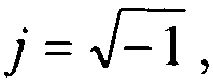

outside of the aperture. That is, the phase modification imposed on the wavefront of incident rays 415 by the combination ofoptics 410 andphase modifying element 510 in this case is αx 3. The second derivative of this phase modification is an expression approximating the focal length across the exit pupil as a function of position:
- In other words, the cubic phase modification provided by the presence of
phase modifying element 510 inEDoF imaging system 500 results in an approximately linear focal length change across the exit pupil. - One way to consider the effects of
phase modifying element 510 inEDoF imaging system 500 is to regardphase modifying element 510 as being composed of a plurality of small optics segments, such as shown inFIG. 6 , with the focal lengths of these lenses linearly changing across the aperture in accordance with the expression α * 6x as derived above. In the example shown inFIG. 6 , anEDoF imaging system 600 includes aphase modifying element 610, which is formed from a plurality ofoptics segments 612A - 612F. The combination ofphase modifying element 610 andoptics 410 provides a linearly changing focal length in accordance with the expression α * 6x, thereby providing the equivalent extended depth of field effect as that provided by the combination ofphase modifying element 510 withoptics 410, as shown inFIG. 5 , assuming the number of optics segments 612 is large enough so that the height of each of the steps amongsegments 612A - 612F is, for example, on the order of a wavelength or less. In other words, the combination ofphase modifying element 610 andoptics 410 images over an extended imaging region 620 (as indicated by a bracket) over a range of imaging distances that is equivalent toextended imaging region 520 provided by the combination ofphase modifying element 510 andoptics 410, as shown inFIG. 5 . - While six
optics segments 612A - 612F are shown inFIG. 6 , more or fewer optics segments may be used in a given EDoF imaging system. A designer of an EDoF imaging system may consideroptics segments 612A - 612F having dimensions on the order of approximately a wavelength of incident illumination of interest, such that a finite number of optics segments would be used in approximating the performance ofEDoF imaging system 600. In such a consideration, the EDoF imaging system may be conceptually regarded as partitioning incident rays withoptics segments 612A - 612F, wherein each optics segment has a focal length that approximately focuses at a particular region along a range of imaging distance. Having extended depth of field means that fewer optics segments may be used to image any one point of an object. Conversely, having a reduced depth of field means that each point of the object is imaged using more of these optics segments. Another way to view this situation is, as more of these optics segments are used to image each point of a given object, then a height of a resulting through-focus modulation transfer function ("MTF") for these object points will increase; on the other hand, as fewer optics segments are used to image each object point, the height of the resulting through-focus MTF for these points will decrease. It should be noted that this description is a simplified, one-dimensional first order approximation of the present system and should be considered illustrative only. - Rather than requiring imaging over a broad range of imaging distances, the multi-region imaging system may be configured to simultaneously image objects located at specific, possibly non-adjacent regions in the object space. For example, these non-adjacent regions may not be contiguous in object space. As a result, a multi-region imaging system may exhibit higher MTF heights and simpler configurations compared to prior imaging systems, as will be further discussed immediately hereinafter.
- Consider the multi-region imaging system shown in
FIG. 7 . Instead of requiring that the combination of optics image objects along a broad range of imaging distances, as shown inFIGS. 5 and6 , each portion of the imaging system aperture is used to image only a specific region in object space. In the example shown inFIG. 7 , amulti-region imaging system 700 includes aphase modifying element 710, including a plurality ofoptics segments 712A - 712D.Optics segments optics 410 so as to image in a near region 720 (as indicated by a bracket) over a range of near imaging distances.Optics segments optics 410 so as to image in a far region 725 (as indicated by another bracket) over a range of far imaging distances. Certain conjugate distances in object space may fall into a "don't care"region 730 that does not need to be imaged. Due to the finite total MTF limitation described earlier, having distinct object regions and/or "don't care" regions allows higher through-focus MTF heights for those object regions of interest, specifically innear region 720 andfar region 725. Viewed another way,multi-region imaging system 700 provides a single imaging system that is equivalent in performance to another system that uses distinct sets of imaging optics for imaging over non-adjacent, narrow regions in object space. Like phase modifying element 610(FIG. 6 ) being broken up into six segments 621A-612F,phase modifying element 710 is shown assegments 712A-712F for illustrative purposes only. That is,phase modifying element 710 may have other configurations, such as curved segments or a continuous aspheric surface. - Still referring to
FIG. 7 ,multi-region imaging system 700 is configured such that the upper half of the aperture (i.e.,optics segments optics segments optics segments 
where the αx 3 term corresponds to a cubic phase term. The term Lower(x) equals zero for the upper half of the aperture (i.e.,optics segments optics segments -
FIG. 8 shows aplot 800 of an exemplary one dimensional exit pupil phase profile, in accordance with the above multi-region exit pupil phase expression of Eq. (8), with α = 5 and β = 40. The vertical axis represents aperture phase in radians, while the horizontal axis shows aperture dimension x in arbitrary units. As may be seen inFIG. 7 , the aperture phase is zero or less for the upper half of the aperture (i.e., throughoptics segments optics segments - An ambiguity function ("AF")
plot 900 related to a diffraction-limited imaging system, such as that exemplified byFIG. 4 , is shown inFIG. 9 . The horizontal axis ("u-axis") inplot 900 represents spatial frequency analogous to the spatial frequency axis of an MTF plot. As is known in the art of AF analysis, the vertical axis ("v-axis") has no direct relationship to the physical imaging system, but the projection of radial slices of the AF onto the horizontal axis may be interpreted as the MTF of this imaging system for varying amounts of misfocus. As is known in the art of AF analysis, darker shades inFIG. 9 represent higher MTF values. In other words, radial cross-sectional slices of the AF yield MTF curves for different values of misfocus and spatial frequency. As is well known in the art, the AF represents a polar display of the MTF as a function of misfocus, and radial lines through anorigin 940 ofAF plot 900 represent the MTF at varying degrees of misfocus. A radial line with zero slope (e.g., dotted line 910) corresponds to MTF at zero misfocus, radial lines with increasing slopes (e.g., dotted line 920) correspond to the MTF at increasing misfocus, and a vertical line (e.g., dotted line 930) throughAF plot 900 corresponds to the through-focus MTF at a particular spatial frequency u. It may be noted that the diffraction-limited AF, as represented byplot 900, is narrow in the vertical direction, thereby indicating high sensitivity of the resulting MTF to misfocus; that is, away from the horizontal radial line corresponding to a zero misfocus value (i.e., dotted line 910), the MTF curves corresponding toAF plot 900 exhibit very sharp peaks with low MTF values away from the sharp peaks, thereby indicating poor imaging quality outside of a very narrow conjugate distance range. -
FIGS. 10 and 11 show AF plots 1000 and 1100 for a cubic phase imaging system with α = 10 (such as, for example, that shown inFIG. 4 and in accordance with Eqs. (5) and (6)) and for a multi-region imaging system with α = 5 and β = 40 (e.g., that shown inFIG. 7 and in accordance with Eq. (8)), respectively. InFIG. 10 , aslanted radial line 1020 corresponds to the MTF at non-zero misfocus for the cubic phase imaging system, and avertical line 1030 corresponds to the through-focus MTF at a particular spatial frequency. Similarly, inFIG. 11 , aslanted radial line 1120 corresponds to the MTF at non-zero misfocus for the multi-region imaging system, and a vertical line 1130 corresponds to the through-focus MTF at a particular spatial frequency. It may be seen that, in contrast to the diffraction limited imaging system AF plot ofFIG. 9 , both the cubic phase imaging system and the multi-region imaging system exhibit ambiguity functions with broader dark regions in the vertical direction, corresponding to higher MTF values; that is, rather than a narrow dark line at the zero slope as inAF plot 900,AF plots AF plots FIGS. 10 and 11 indicate that these imaging systems exhibit good imaging quality even with non-zero misfocus values. It is known that an ambiguity function represents optical MTF, and a system's sensor spatial frequency limit is typically half or less than the system's optical limit; the extent of a typical spatial frequency extent for a digital sensor is indicated bybrackets FIGS. 10 and 11 , respectively. Furthermore,AF plot 1100 corresponding to the multi-region imaging system exhibits two clear regions of best focus separated by a "don't care" region (indicated by two dashedovals - A number of variations to the multi-region imaging system are possible. While the example illustrated in
FIGS. 7 and11 assumed a rectangularly separable exit pupil phase, other types of phase modification such as, but not limited to, circularly symmetric phase, symmetric phase or non-symmetric exit pupil phase may also be used, according to a desired application. The use of polychromatic (that is, wavelength-dependent) exit pupil phase design is also possible, and the phase modification may be effected by, for instance, phase modulating optics with subwavelength features. Alternatively, the phase modification may be implemented using polarization-dependent optical elements. -
FIG. 12 shows a block diagram of an exemplarymulti-region imaging system 1200.FIG. 12 is a particular example of the general multi-region imaging system block diagram as shown inFIG. 3 .Multi-region imaging system 1200 includes anoptics group 1210, which in turn includes a plano/aspheric element 1220(1) at the front of the imaging system, and first and second K5/F2 doublets Optics group 1210 is configured to directincident rays 1250 toward asensor 1260.Sensor 1260 may be, but not limited to, a complementary metal oxide semiconductor ("CMOS") sensor configured for receiving aportion 1265 ofincident rays 1250, and for generating image data 1270 (represented by a dark arrow) in response thereto.Image data 1270 may then be received at aprocessor 1280 for image processing to form, for instance, a human-viewable image and/or a processing result for a task, such as bar code reading. The image processing may utilize information ofoptics group 1210 to form the human-viewable image and/or the processing result so as to form images that are sharp and clear in best focus regions of a scene imaged thereby, as discussed below.TABLE 1 Surface Type Radius Thickness Glass Diameter Conic Object Standard Infinity Infinity 0 0 1291 Standard Infinity 0.3804 PMMA 1.347194 0 1292(1)/Stop Evenasph Infinity 0.007652431 1.347194 0 1293 Standard 3.285444 0.8864066 K5 2.48704 0 1294 Standard - 2.354398 0.2933432 F2 2.48704 0 1295 Standard - 28.18008 2.168189 2.48704 0 1296 Standard 2.883053 0.8417674 K5 2.104418 0 1297 Standard - 1.508167 0.242327 F2 2.104418 0 1298 Standard - 5.335657 1.551752 2.104418 0 Image Standard Infinity 0.0004286271 0 - An exemplary prescription for the various optical surfaces for
multi-region imaging system 1200 ofFIG. 12 is summarized in TABLE 1, with the different surfaces (i.e., surfaces 1291 through 1298) as labeled inFIG. 12 . A radius of curvature value of "infinity" corresponds to a plano surface. Prescription details related to plano/aspheric element 1220 are further discussed immediately hereinafter in the following two examples. - When the multi-region imaging system described in reference to
FIG. 12 and TABLE 1 is modified by replacing plano/aspheric element 1220(1) with a plano/plano element 1220(2) (e.g., element 1220(2) has a second surface 1292(2) with no curvature) providing no phase modulation, thenoptics group 1210 produces a through-focus MTF curve 1300 at a spatial frequency of 100 line pairs per millimeter ("lp/mm"), as shown inFIG. 13 . The resulting imaging system is essentially a traditional imaging system without phase modification or multi-region imaging characteristics. As expected, through-focus MTF curve 1300 exhibits a singlebest focus peak 1310 with a peak height of approximately 0.8 in n01111a1ized units and a narrow peak width 1320 (indicated by a double-headed arrow) and, consequently, a narrow depth of focus.TABLE 2 SURFACE 1292(1) EVENASPH Coefficient on r2 0 Coefficient on r4 0.012940072 Coefficient on r6 0.33257242 Coefficient on r8 -1.4950249 Coefficient on r10 -0.26830899 Coefficient on r12 8.0415913 Coefficient on r14 -8.6162206 Figure 14 shows an embodiment which does not form part of the invention, and serves for illustrative purposes only -
FIG. 14 shows anexemplary aspheric surface 1400 suitable for use as surface 1292(1) of plano/aspheric element 1220(1) inmulti-region imaging system 1200 ofFIG. 12 . Aspheric coefficients corresponding toaspheric surface 1400 are summarized in TABLE 2. With the inclusion ofaspheric surface 1400 assurface 10 1292(1) inoptics group 1210, a through-focus MTF curve 1500, as shown inFIG. 15 , results at a spatial frequency of 100 1p/mm. Through-focus MTF curve 1500 includes first and secondbest focus regions region 1540, that is, through-focus MTF curve 1500 indicates that there is more than one region of focus shifts that correspond to best focus (two regions, in this example). 15 It is understood that each region of best focus corresponds to an object distance range, that is, a range of distance of an object from the multi-region imaging system (e.g., distances ofobjects multi-region optics 310,FIG. 3 ). All ofregions FIG. 14 , since they are separated byregion 1540,regions FIG. 1 , firstbest focus region 1510 may correspond to near field imaging of, for example,barcode 30 or a business card (e.g., a conjugate distance of ∼ 13 to 18 cm), while secondbest focus region 1515 may correspond to far 25 field imaging used for human viewed portrait imaging (e.g., a conjugate distance of ∼60 cm or greater, such thatbest focus regions focus MTF curve 1500 in first and secondbest focus regions region 1540 do not need to be low, the reduced through-focus MTF values in "don't care" region contributes to increased through-focus MTF values in first and secondbest focus regions second peaks -
FIGS. 16 - 19 show diffraction MTF curves for polychromatic (e.g., white) light foroptics group 1210 inmulti-region imaging system 1200 ofFIG. 12 , includingaspheric surface 1400 ofFIG. 14 as surface 1292(1), at different conjugate distances.FIG. 16 shows anMTF curve 1600 for a conjugate distance of infinity, andFIG. 17 shows anMTF curve 1700 for a conjugate distance of 60cm. It may be noted that the values ofMTF curves FIGS. 16 and17 , thereby indicating thatmulti-region imaging system 1200 exhibits a high MTF value throughout the far field imaging region at conjugate distances of 60 cm or greater (e.g., corresponding toregion 1515,FIG. 15 ).FIG. 18 shows anMTF curve 1800 for a conjugate distance of 25 cm (i.e., in "don't care"region 1540,FIG. 15 , between near field and far field); it may be seen thatMTF curve 1800 drops off quickly for spatial frequencies above ∼30 or 40 cycles per millimeter, thereby indicating poor image quality in this "don't care" region. Finally,FIG. 19 shows anMTF curve 1900 for a conjugate distance of 15 cm (e.g., corresponding toregion 1510,FIG. 15 ), which is suitable for near field imaging application such as barcode imaging and business card reading. As may be seen inFIG. 19 ,MTF curve 1900 exhibits relatively high MTF values (e.g., ∼0.2 and higher) throughout the spatial frequency region of interest, thereby indicating good imaging performance even at this near field conjugate distance for the multi-region imaging system includingoptics group 1210.TABLE 3 Surface Type Radius Thickness Glass Diameter Conic Object Standard Infinity Infinity 0 0 1291 Standard Infinity 0.3804 PMMA 1.347194 0 1292/Stop Evenasph Infinity 0.07652431 1.347194 0 1293 Standard 3.285444 0.8864066 K5 2.48704 0 1294 Standard -2.354398 0.2933432 F2 2.48704 0 1295 Standard -28.18008 2.168189 2.48704 0 1296 Standard 2.883053 0.8417674 K5 2.104418 0 1297 Standard -1.508167 0.242327 F2 2.104418 0 1298 Standard -5.335657 1.487967 2.104418 0 Image Standard Infinity 0.05080852 0 TABLE 4 SURFACE 1292(3) EVENASPH Coefficient on r2 0 Coefficient on r4 -0.03062278 Coefficient on r6 0.0042801507 Coefficient on r8 0.043959156 Coefficient on r10 0.10487482 Coefficient on r12 -0.073525074 Coefficient on r14 -0.32282005 -
FIG. 20 shows a through-focus MTF curve 2000, at a spatial frequency of 100 lp/mm, for an alternative imaging system that has been optimized to provide better imaging performance at 25 cm conjugate distance compared to that of the multi-region imaging system whose through-focus MTF curve is shown inFIG. 15 . That is, the alternative imaging system essentially includes the components ofmulti-region imaging system 1200 ofFIG. 12 but with a prescription that is summarized in TABLES 3 and 4. The alternative imaging system includes a plano/aspheric element 1220(3), having a second surface 1292(3) with aspheric coefficients summarized in TABLE 4, to provide better imaging performance at 25 cm conjugate distance. It may be noted that through-focus MTF curve 2000 for the alternative multi-region imaging system includes multiple, wide humps rather than a single narrow peak or two distinct peaks as in the previously discussed embodiments. Further differences in system performance may be seen by comparing the polychromatic diffraction MTF curves shown inFIGS. 21 - 24 , for the alternative multi-region imaging system, with those shown inFIGS. 16 - 19 , corresponding to the performance ofoptics group 1210 ofmulti-region imaging system 1200 includingaspheric surface 1400 as surface 1292(1).FIG. 21 shows anMTF curve 2100 far a conjugate distance of infinity,FIG. 22 shows anMTF curve 2200 for a conjugate distance of 60 cm,FIG. 23 shows anMTF curve 2300 for a conjugate distance of 25 5 cm, andFIG. 24 shows anMTF curve 2400 far a conjugate distance of 15 cm. In comparingFIGS. 21 - 24 with earlier describedFIGS. 16 - 19 , it may be seen that the MTF curves far the alternative imaging system, while providing slightly better performance at 25 cm, are generally lower across the portrait and bar code regions.TABLE 5 SURFACE 1292(4) CUSPLINE Z at 1/8 of S-D -0.0010485351 Z at 2/8 of S-D -0.0010594568 Z at 3/8 of S-D -0.00082374686 Z at 4/8 of S-D -0.00057644724 Z at 5/8 of S-D 0 Z at 6/8 of S-D 0 Z at 7/8 of S-D 0 Z at 8/8 of S-D 0 - There are many design methods that may be used to achieve multi-region imaging systems. Some examples were described. Aspects of each of these examples may be combined, by those skilled in the art of optical/digital imaging systems, to form new systems within the scope hereof.
- Some possible combinations of features for the multi-region imaging system are:
- 1. OPD-modifying optics + digital signal processing ("DSP") for two 01' mare best focus imaging regions;
- 2. OPD-modifying optics + DSP for two or more best focus imaging regions for human viewed systems;
- 3. OPD-modifying optics + DSP for task based imaging over two ar more best focus imaging regions;
- 4. OPD-modifying optics far forming two or more best focus imaging regions where the through focus MTF related to at least one region is broader, or has an extended depth of field, than without the OPD-modifying optics;
- 5. OPD-modifying optics from 4 that include continuous phase modifications;
- 6. OPD-modifying optics from 4 that include discontinuous phase optics;
- 7. OPD-modifying optics from 4 that use specially designed chromatic aberration;
- 8. OPD-modifying optics from 4 that use sub-wavelength phase variations;
- 9. OPD-modifying optics + DSP for two or more best focus imaging regions for mobile phone applications;
- 10. OPD-modifying optics + DSP for task based imaging over two or more best focus imaging regions for automotive applications;
- 11. OPD-modifying optics from 4 that are illumination dependent.
- 12. OPD-modifying sensors (electronics + package + cover glass) for multi-region imaging;
- 13. Use of 12 for automobile applications; and
- 14. OPD-modifying multi-region imaging where spatial changes in focus at the image plane are realized.
Claims (8)
- A multi-region imaging system configured to simultaneously image objects located at specific non-adjacent regions in the object space, comprising:a single aperture that limits light rays (1250) entering the imaging system (1210);imaging optics (1230, 1240);an optical pathlength difference(OPD)-modifying element (1220) and a sensor array (1260), the imaging optics (1230, 1240) and the OPD-modifying element (1220) forming an optical image at the sensor array, the sensor array (1260) converting the optical image to a data stream (1270); anda digital signal processor (1280) for processing the data stream to generate a final image;wherein the OPD-modifying element (1220) imparts a continuous phase modification, to provide the first and second regions in the optical image corresponding to object distance ranges that are discontiguous, the continuous phase modification comprising a phase function of:
 where α and β are constants specified such that the OPD-modifying element (1220) provides a first region in the optical image that is characterized by a first range of best focus and a second region in the optical image that is characterized by a second range of best focus, the first range and the second range corresponding to object distance ranges that are discontiguous and, Lower(x) is zero for x in an upper half of the OPD-modifying element, and unity for x in a lower half of the OPD-modifying element, wherein the boundary between the upper half and the lower half of the OPD-modifying element is located at x=0.
 - The imaging system of claim 1, wherein the OPD-modifying element (1220) comprises at least one of a molded material, an optical element including subwavelength phase modifying features and a material including refractive index variation therein.
- The imaging system of claim 1, wherein the OPD-modifying element (1220) provides spatial changes in focus at the optical image.
- Method of imaging objects located at specific, non-adjacent regions in the object space, utilizing an imaging system according to any one of the preceding claims,
such that
electromagnetic energy transmitted through the single aperture, subsequently through the imaging optics and incident on the sensor array forms an image that is in focus over at least two conjugate distance ranges for two respective portions of the image,
the two conjugate distance ranges being separated by at least 40 cm. - The method of claim 4, wherein the phase modifying element generates the two respective portions of the image.
- The method of claim 4, wherein configuring the imaging optics with the phase modifying element comprises integrating, into the imaging optics, at least one of a transparent plate covering a portion of the sensor array, an aspheric element and a power-providing optical element.
- The method of claim 4, wherein configuring the imaging optics with the phase modifying element comprises integrating, into the imaging optics, at least one of a molded material, an optical element including subwavelength phase modifying features and a material including refractive index variation therein.
- The method of claim 4, wherein incorporating the phase modifying element comprises arranging the phase modifying element for providing spatial changes in focus at an image plane of the imaging optics.
Applications Claiming Priority (3)
| Application Number | Priority Date | Filing Date | Title |
|---|---|---|---|
| US95399807P | 2007-08-04 | 2007-08-04 | |
| US5673008P | 2008-05-28 | 2008-05-28 | |
| PCT/US2008/072112 WO2009020918A1 (en) | 2007-08-04 | 2008-08-04 | Multi-region imaging systems |
Publications (2)
| Publication Number | Publication Date |
|---|---|
| EP2183635A1 EP2183635A1 (en) | 2010-05-12 |
| EP2183635B1 true EP2183635B1 (en) | 2015-09-16 |
Family
ID=39885222
Family Applications (1)
| Application Number | Title | Priority Date | Filing Date |
|---|---|---|---|
| EP08797119.8A Active EP2183635B1 (en) | 2007-08-04 | 2008-08-04 | Multi-region imaging systems |
Country Status (5)
| Country | Link |
|---|---|
| US (3) | US8736699B2 (en) |
| EP (1) | EP2183635B1 (en) |
| CN (1) | CN101861542B (en) |
| TW (1) | TWI495337B (en) |
| WO (1) | WO2009020918A1 (en) |
Families Citing this family (36)
| Publication number | Priority date | Publication date | Assignee | Title |
|---|---|---|---|---|
| WO2010103527A2 (en) * | 2009-03-13 | 2010-09-16 | Ramot At Tel-Aviv University Ltd. | Imaging system and method for imaging objects with reduced image blur |
| WO2011003381A1 (en) | 2009-07-06 | 2011-01-13 | Conti Temic Microelectronic Gmbh | Optical module for simultaneously focusing on two fields of view |
| US8531783B2 (en) | 2010-02-09 | 2013-09-10 | Xceed Imaging Ltd. | Imaging method and system for imaging with extended depth of focus |
| JP5466766B2 (en) * | 2010-10-01 | 2014-04-09 | 富士フイルム株式会社 | Imaging device |
| WO2012054059A1 (en) * | 2010-10-22 | 2012-04-26 | Hewlett-Packard Development Company L.P. | Altering focus lens magnification in a video frame |
| DE102010043479B4 (en) * | 2010-11-05 | 2019-03-07 | Robert Bosch Gmbh | Camera arrangement and method for operating a camera arrangement for a motor vehicle |
| CN103221805B (en) | 2010-11-30 | 2016-10-12 | 康蒂特米克微电子有限公司 | Detection of raindrops on window panes with the aid of cameras and lighting |
| US9270948B2 (en) * | 2011-04-27 | 2016-02-23 | Panasonic Intellectual Property Management Co., Ltd. | Image pick-up device, method, and system utilizing a lens having plural regions each with different focal characteristics |
| DE102011103302A1 (en) | 2011-06-03 | 2012-12-06 | Conti Temic Microelectronic Gmbh | Camera system for a vehicle |
| WO2013001709A1 (en) * | 2011-06-27 | 2013-01-03 | パナソニック株式会社 | Image pickup apparatus |
| WO2013027488A1 (en) * | 2011-08-24 | 2013-02-28 | 富士フイルム株式会社 | Imaging device |
| US8729653B2 (en) | 2011-10-26 | 2014-05-20 | Omnivision Technologies, Inc. | Integrated die-level cameras and methods of manufacturing the same |
| CN103094702B (en) * | 2011-10-31 | 2015-11-18 | 深圳光启高等理工研究院 | Based on the antenna of Meta Materials |
| CN103314571B (en) * | 2011-11-30 | 2017-09-29 | 松下知识产权经营株式会社 | Cameras and Camera Systems |
| DE102011056051A1 (en) | 2011-12-05 | 2013-06-06 | Conti Temic Microelectronic Gmbh | Method for evaluating image data of a vehicle camera taking into account information about rain |
| US20130208121A1 (en) * | 2012-02-10 | 2013-08-15 | Xerox Corporation | Traffic camera diagnostics via test targets |
| JP2013222066A (en) * | 2012-04-17 | 2013-10-28 | Hitachi Ltd | Phase filter and imaging camera system including the same |
| DE102012103873A1 (en) | 2012-05-03 | 2013-11-21 | Conti Temic Microelectronic Gmbh | Detecting raindrops on a glass by means of a camera and lighting |
| TWI470273B (en) * | 2012-09-07 | 2015-01-21 | Young Optics Inc | Lens module and projection apparatus and image pick-up device having the same |
| US10442774B1 (en) * | 2012-11-06 | 2019-10-15 | Valve Corporation | Adaptive optical path with variable focal length |
| US20140178314A1 (en) | 2012-12-19 | 2014-06-26 | The Procter & Gamble Company | Compositions and/or articles with improved solubility of a solid active |
| JP6396638B2 (en) | 2013-03-29 | 2018-09-26 | マクセル株式会社 | Phase filter, imaging optical system, and imaging system |
| DE102013220005A1 (en) * | 2013-10-02 | 2015-04-02 | Continental Automotive Gmbh | Method and device for displaying the environment of a vehicle and driver assistance system |
| JP2015165610A (en) * | 2014-02-28 | 2015-09-17 | 株式会社リコー | Imaging apparatus, imaging system, and imaging method |
| US9185306B1 (en) * | 2014-05-15 | 2015-11-10 | Symbol Technologies, Llc | Imaging module and reader for, and method of, illuminating and imaging targets to be read over an extended range of working distances |
| US10027928B2 (en) * | 2014-10-28 | 2018-07-17 | Exnodes Inc. | Multiple camera computational wafer inspection |
| US20170099427A1 (en) * | 2015-10-05 | 2017-04-06 | Google Inc. | Methods and apparatuses for providing improved autofocus using curve-fitting |
| US10114454B2 (en) * | 2016-06-22 | 2018-10-30 | Microsoft Technology Licensing, Llc | Velocity and depth aware reprojection |
| US10129523B2 (en) | 2016-06-22 | 2018-11-13 | Microsoft Technology Licensing, Llc | Depth-aware reprojection |
| US10237531B2 (en) | 2016-06-22 | 2019-03-19 | Microsoft Technology Licensing, Llc | Discontinuity-aware reprojection |
| US20180054569A1 (en) * | 2016-08-19 | 2018-02-22 | Delphi Technologies, Inc. | Dual-focus camera for automated vehicles |
| US11209633B2 (en) * | 2018-02-26 | 2021-12-28 | Fotonation Limited | Iris image acquisition system |
| CN108802989B (en) * | 2018-08-17 | 2020-06-02 | 华中科技大学 | A parallel multi-region imaging device |
| CN109600537B (en) * | 2018-12-17 | 2020-10-20 | 上海摩软通讯技术有限公司 | Imaging device and method |
| US11310438B2 (en) * | 2019-04-19 | 2022-04-19 | Direct Electron, Lp | System, apparatus, and method for determining elemental composition using 4D STEM |
| WO2024052889A1 (en) * | 2022-09-09 | 2024-03-14 | Immervision, Inc. | Optical system with localized magnification |
Citations (4)
| Publication number | Priority date | Publication date | Assignee | Title |
|---|---|---|---|---|
| US5814803A (en) * | 1994-12-23 | 1998-09-29 | Spectra-Physics Scanning Systems, Inc. | Image reader with multi-focus lens |
| WO2003052465A2 (en) * | 2001-12-18 | 2003-06-26 | University Of Rochester | Multifocal aspheric lens obtaining extended field depth |
| JP2005292544A (en) * | 2004-04-01 | 2005-10-20 | Matsushita Electric Ind Co Ltd | Focus adjustment mechanism |
| JP2006184844A (en) * | 2004-12-03 | 2006-07-13 | Tochigi Nikon Corp | Imaging optical system and imaging apparatus using the same |
Family Cites Families (17)
| Publication number | Priority date | Publication date | Assignee | Title |
|---|---|---|---|---|
| US5524162A (en) * | 1991-07-22 | 1996-06-04 | Levien; Raphael L. | Method and apparatus for adaptive sharpening of images |
| US5627366A (en) * | 1995-05-19 | 1997-05-06 | Symbol Technologies, Inc. | Optical scanner with extended depth of focus |
| US6122009A (en) * | 1995-05-31 | 2000-09-19 | Sony Corporation | Image pickup apparatus fabrication method thereof image pickup adaptor apparatus signal processing apparatus signal processing method thereof information processing apparatus and information processing method |
| US5746371A (en) | 1995-12-29 | 1998-05-05 | Ben-Haim; Amit | Cutting brick folding carton and blank |
| EP1396737A3 (en) * | 1997-03-11 | 2004-12-29 | Nihon Kohden Corporation | Particle analyzer and composite lens formed by integrally joining plural lens elements of different focal points |
| JP3554703B2 (en) | 2000-10-12 | 2004-08-18 | リバーベル株式会社 | Information terminal equipment |
| US6749120B2 (en) * | 2000-12-11 | 2004-06-15 | Cpo Technologies Corp. | Method and apparatus for scanning electronic barcodes |
| US6618206B2 (en) * | 2001-10-20 | 2003-09-09 | Zonare Medical Systems, Inc. | System and method for acoustic imaging at two focal lengths with a single lens |
| US20060269150A1 (en) | 2005-05-25 | 2006-11-30 | Omnivision Technologies, Inc. | Multi-matrix depth of field image sensor |
| JP4456040B2 (en) * | 2005-06-17 | 2010-04-28 | パナソニック株式会社 | Solid-state image sensor |
| DE102005036486A1 (en) * | 2005-07-20 | 2007-01-25 | Leica Microsystems (Schweiz) Ag | Optical device with increased depth of field |
| WO2007014216A2 (en) * | 2005-07-22 | 2007-02-01 | Cernium Corporation | Directed attention digital video recordation |
| US7946491B2 (en) * | 2006-08-03 | 2011-05-24 | Nokia Corporation | Method, apparatus, and computer program product for providing a camera barcode reader |
| US8223235B2 (en) | 2007-12-13 | 2012-07-17 | Motorola Mobility, Inc. | Digital imager with dual rolling shutters |
| CN102334128B (en) | 2008-12-26 | 2015-03-25 | 数据逻辑扫描公司 | Systems and methods for imaging |
| JP2011015222A (en) | 2009-07-02 | 2011-01-20 | Fujifilm Corp | Imaging apparatus, and imaging control method |
| US8350922B2 (en) | 2010-04-30 | 2013-01-08 | Ecole Polytechnique Federale De Lausanne | Method to compensate the effect of the rolling shutter effect |
-
2008
- 2008-08-04 TW TW097129555A patent/TWI495337B/en active
- 2008-08-04 WO PCT/US2008/072112 patent/WO2009020918A1/en not_active Ceased
- 2008-08-04 CN CN200880110346.XA patent/CN101861542B/en active Active
- 2008-08-04 US US12/672,257 patent/US8736699B2/en active Active
- 2008-08-04 EP EP08797119.8A patent/EP2183635B1/en active Active
-
2011
- 2011-09-13 US US13/231,826 patent/US8593552B2/en active Active
-
2013
- 2013-11-25 US US14/089,410 patent/US9471994B2/en active Active
Patent Citations (4)
| Publication number | Priority date | Publication date | Assignee | Title |
|---|---|---|---|---|
| US5814803A (en) * | 1994-12-23 | 1998-09-29 | Spectra-Physics Scanning Systems, Inc. | Image reader with multi-focus lens |
| WO2003052465A2 (en) * | 2001-12-18 | 2003-06-26 | University Of Rochester | Multifocal aspheric lens obtaining extended field depth |
| JP2005292544A (en) * | 2004-04-01 | 2005-10-20 | Matsushita Electric Ind Co Ltd | Focus adjustment mechanism |
| JP2006184844A (en) * | 2004-12-03 | 2006-07-13 | Tochigi Nikon Corp | Imaging optical system and imaging apparatus using the same |
Also Published As
| Publication number | Publication date |
|---|---|
| CN101861542A (en) | 2010-10-13 |
| TWI495337B (en) | 2015-08-01 |
| WO2009020918A1 (en) | 2009-02-12 |
| US20120069205A1 (en) | 2012-03-22 |
| CN101861542B (en) | 2016-04-20 |
| US8593552B2 (en) | 2013-11-26 |
| US20140078314A1 (en) | 2014-03-20 |
| EP2183635A1 (en) | 2010-05-12 |
| US8736699B2 (en) | 2014-05-27 |
| US9471994B2 (en) | 2016-10-18 |
| TW200920113A (en) | 2009-05-01 |
| US20110085050A1 (en) | 2011-04-14 |
Similar Documents
| Publication | Publication Date | Title |
|---|---|---|
| US8736699B2 (en) | Multi-region imaging systems | |
| US20220390721A1 (en) | Optical imaging system | |
| US10359608B2 (en) | Bifocal lens and imaging device including same | |
| US20040004766A1 (en) | Wavefront coded imaging systems | |
| KR101309423B1 (en) | Hyper-field fish eye lens | |
| US10895716B2 (en) | Electronic device | |
| US11927730B2 (en) | Optical imaging system | |
| US8289624B2 (en) | Imaging lens system | |
| JP6985410B2 (en) | Imaging lens system and imaging device | |
| KR101691351B1 (en) | Photographic Lens Optical System | |
| US8391705B2 (en) | Folded optic, camera system including the same, and associated methods | |
| JP2013511736A (en) | Fixed focal length optical lens architecture that composes a customized focal depth optical system | |
| US20210263267A1 (en) | Optical imaging system | |
| TWI861042B (en) | Optical system and cameramodule including the same | |
| CN101052910B (en) | Low-height imaging system and related method | |
| EP2693249A1 (en) | Focus extending optical system and edof imaging system | |
| JP6748856B2 (en) | Monofocal lens system, imaging device having monofocal lens system, and moving body having imaging device | |
| US20220187570A1 (en) | Photographing optical lens system, image capturing unit and electronic device | |
| CN105137576B (en) | Varifocal imaging camera lens, imaging modules and iris identification device | |
| WO2007134119A1 (en) | Aberration-tolerant far infrared imaging system | |
| EP4071534B1 (en) | Optical imaging lens assembly, image capturing unit and electronic device | |
| JP7804109B2 (en) | Imaging lens system and imaging device | |
| CN109116513B (en) | Optical lens module | |
| EP4191314B1 (en) | Optical imaging system, image capturing unit and electronic device | |
| EP1353207B1 (en) | Telecentric singlet having a small height requirement |
Legal Events
| Date | Code | Title | Description |
|---|---|---|---|
| PUAI | Public reference made under article 153(3) epc to a published international application that has entered the european phase |
Free format text: ORIGINAL CODE: 0009012 |
|
| 17P | Request for examination filed |
Effective date: 20100304 |
|
| AK | Designated contracting states |
Kind code of ref document: A1 Designated state(s): AT BE BG CH CY CZ DE DK EE ES FI FR GB GR HR HU IE IS IT LI LT LU LV MC MT NL NO PL PT RO SE SI SK TR |
|
| AX | Request for extension of the european patent |
Extension state: AL BA MK RS |
|
| RIN1 | Information on inventor provided before grant (corrected) |
Inventor name: DOBBS, DENNIS, W. Inventor name: TAMAYO, INGA Inventor name: DOWSKI, EDWARD, R. Inventor name: KUBALA, KENNETH, S. Inventor name: TACHIHARA, SATORU Inventor name: PENNIMAN, EDWIN |
|
| DAX | Request for extension of the european patent (deleted) | ||
| 17Q | First examination report despatched |
Effective date: 20120613 |
|
| RAP1 | Party data changed (applicant data changed or rights of an application transferred) |
Owner name: OMNIVISION TECHNOLOGIES, INC. |
|
| REG | Reference to a national code |
Ref country code: DE Ref legal event code: R079 Ref document number: 602008040217 Country of ref document: DE Free format text: PREVIOUS MAIN CLASS: G02B0027000000 Ipc: G02B0003100000 |
|
| RIC1 | Information provided on ipc code assigned before grant |
Ipc: G02B 26/06 20060101ALI20150130BHEP Ipc: G02B 27/00 20060101ALI20150130BHEP Ipc: G02B 3/10 20060101AFI20150130BHEP |
|
| GRAP | Despatch of communication of intention to grant a patent |
Free format text: ORIGINAL CODE: EPIDOSNIGR1 |
|
| INTG | Intention to grant announced |
Effective date: 20150318 |
|
| GRAS | Grant fee paid |
Free format text: ORIGINAL CODE: EPIDOSNIGR3 |
|
| GRAA | (expected) grant |
Free format text: ORIGINAL CODE: 0009210 |
|
| AK | Designated contracting states |
Kind code of ref document: B1 Designated state(s): AT BE BG CH CY CZ DE DK EE ES FI FR GB GR HR HU IE IS IT LI LT LU LV MC MT NL NO PL PT RO SE SI SK TR |
|
| REG | Reference to a national code |
Ref country code: GB Ref legal event code: FG4D |
|
| REG | Reference to a national code |
Ref country code: CH Ref legal event code: EP |
|
| REG | Reference to a national code |
Ref country code: IE Ref legal event code: FG4D |
|
| REG | Reference to a national code |
Ref country code: AT Ref legal event code: REF Ref document number: 750224 Country of ref document: AT Kind code of ref document: T Effective date: 20151015 |
|
| REG | Reference to a national code |
Ref country code: DE Ref legal event code: R096 Ref document number: 602008040217 Country of ref document: DE |
|
| REG | Reference to a national code |
Ref country code: CH Ref legal event code: NV Representative=s name: BRAUNPAT BRAUN EDER AG, CH |
|
| REG | Reference to a national code |
Ref country code: NL Ref legal event code: MP Effective date: 20150916 |
|
| PG25 | Lapsed in a contracting state [announced via postgrant information from national office to epo] |
Ref country code: FI Free format text: LAPSE BECAUSE OF FAILURE TO SUBMIT A TRANSLATION OF THE DESCRIPTION OR TO PAY THE FEE WITHIN THE PRESCRIBED TIME-LIMIT Effective date: 20150916 Ref country code: LT Free format text: LAPSE BECAUSE OF FAILURE TO SUBMIT A TRANSLATION OF THE DESCRIPTION OR TO PAY THE FEE WITHIN THE PRESCRIBED TIME-LIMIT Effective date: 20150916 Ref country code: NO Free format text: LAPSE BECAUSE OF FAILURE TO SUBMIT A TRANSLATION OF THE DESCRIPTION OR TO PAY THE FEE WITHIN THE PRESCRIBED TIME-LIMIT Effective date: 20151216 Ref country code: GR Free format text: LAPSE BECAUSE OF FAILURE TO SUBMIT A TRANSLATION OF THE DESCRIPTION OR TO PAY THE FEE WITHIN THE PRESCRIBED TIME-LIMIT Effective date: 20151217 Ref country code: LV Free format text: LAPSE BECAUSE OF FAILURE TO SUBMIT A TRANSLATION OF THE DESCRIPTION OR TO PAY THE FEE WITHIN THE PRESCRIBED TIME-LIMIT Effective date: 20150916 |
|
| REG | Reference to a national code |
Ref country code: LT Ref legal event code: MG4D |
|
| REG | Reference to a national code |
Ref country code: AT Ref legal event code: MK05 Ref document number: 750224 Country of ref document: AT Kind code of ref document: T Effective date: 20150916 |
|
| PG25 | Lapsed in a contracting state [announced via postgrant information from national office to epo] |
Ref country code: HR Free format text: LAPSE BECAUSE OF FAILURE TO SUBMIT A TRANSLATION OF THE DESCRIPTION OR TO PAY THE FEE WITHIN THE PRESCRIBED TIME-LIMIT Effective date: 20150916 Ref country code: SE Free format text: LAPSE BECAUSE OF FAILURE TO SUBMIT A TRANSLATION OF THE DESCRIPTION OR TO PAY THE FEE WITHIN THE PRESCRIBED TIME-LIMIT Effective date: 20150916 |
|
| PG25 | Lapsed in a contracting state [announced via postgrant information from national office to epo] |
Ref country code: NL Free format text: LAPSE BECAUSE OF FAILURE TO SUBMIT A TRANSLATION OF THE DESCRIPTION OR TO PAY THE FEE WITHIN THE PRESCRIBED TIME-LIMIT Effective date: 20150916 |
|
| PG25 | Lapsed in a contracting state [announced via postgrant information from national office to epo] |
Ref country code: IT Free format text: LAPSE BECAUSE OF FAILURE TO SUBMIT A TRANSLATION OF THE DESCRIPTION OR TO PAY THE FEE WITHIN THE PRESCRIBED TIME-LIMIT Effective date: 20150916 Ref country code: CZ Free format text: LAPSE BECAUSE OF FAILURE TO SUBMIT A TRANSLATION OF THE DESCRIPTION OR TO PAY THE FEE WITHIN THE PRESCRIBED TIME-LIMIT Effective date: 20150916 Ref country code: IS Free format text: LAPSE BECAUSE OF FAILURE TO SUBMIT A TRANSLATION OF THE DESCRIPTION OR TO PAY THE FEE WITHIN THE PRESCRIBED TIME-LIMIT Effective date: 20160116 Ref country code: SK Free format text: LAPSE BECAUSE OF FAILURE TO SUBMIT A TRANSLATION OF THE DESCRIPTION OR TO PAY THE FEE WITHIN THE PRESCRIBED TIME-LIMIT Effective date: 20150916 Ref country code: EE Free format text: LAPSE BECAUSE OF FAILURE TO SUBMIT A TRANSLATION OF THE DESCRIPTION OR TO PAY THE FEE WITHIN THE PRESCRIBED TIME-LIMIT Effective date: 20150916 Ref country code: ES Free format text: LAPSE BECAUSE OF FAILURE TO SUBMIT A TRANSLATION OF THE DESCRIPTION OR TO PAY THE FEE WITHIN THE PRESCRIBED TIME-LIMIT Effective date: 20150916 |
|
| PG25 | Lapsed in a contracting state [announced via postgrant information from national office to epo] |
Ref country code: AT Free format text: LAPSE BECAUSE OF FAILURE TO SUBMIT A TRANSLATION OF THE DESCRIPTION OR TO PAY THE FEE WITHIN THE PRESCRIBED TIME-LIMIT Effective date: 20150916 Ref country code: PT Free format text: LAPSE BECAUSE OF FAILURE TO SUBMIT A TRANSLATION OF THE DESCRIPTION OR TO PAY THE FEE WITHIN THE PRESCRIBED TIME-LIMIT Effective date: 20160118 Ref country code: PL Free format text: LAPSE BECAUSE OF FAILURE TO SUBMIT A TRANSLATION OF THE DESCRIPTION OR TO PAY THE FEE WITHIN THE PRESCRIBED TIME-LIMIT Effective date: 20150916 Ref country code: RO Free format text: LAPSE BECAUSE OF FAILURE TO SUBMIT A TRANSLATION OF THE DESCRIPTION OR TO PAY THE FEE WITHIN THE PRESCRIBED TIME-LIMIT Effective date: 20150916 |
|
| REG | Reference to a national code |
Ref country code: DE Ref legal event code: R097 Ref document number: 602008040217 Country of ref document: DE |
|
| REG | Reference to a national code |
Ref country code: FR Ref legal event code: PLFP Year of fee payment: 9 |
|
| PLBE | No opposition filed within time limit |
Free format text: ORIGINAL CODE: 0009261 |
|
| STAA | Information on the status of an ep patent application or granted ep patent |
Free format text: STATUS: NO OPPOSITION FILED WITHIN TIME LIMIT |
|
| 26N | No opposition filed |
Effective date: 20160617 |
|
| PG25 | Lapsed in a contracting state [announced via postgrant information from national office to epo] |
Ref country code: DK Free format text: LAPSE BECAUSE OF FAILURE TO SUBMIT A TRANSLATION OF THE DESCRIPTION OR TO PAY THE FEE WITHIN THE PRESCRIBED TIME-LIMIT Effective date: 20150916 |
|
| PG25 | Lapsed in a contracting state [announced via postgrant information from national office to epo] |
Ref country code: SI Free format text: LAPSE BECAUSE OF FAILURE TO SUBMIT A TRANSLATION OF THE DESCRIPTION OR TO PAY THE FEE WITHIN THE PRESCRIBED TIME-LIMIT Effective date: 20150916 |
|
| PG25 | Lapsed in a contracting state [announced via postgrant information from national office to epo] |
Ref country code: BE Free format text: LAPSE BECAUSE OF FAILURE TO SUBMIT A TRANSLATION OF THE DESCRIPTION OR TO PAY THE FEE WITHIN THE PRESCRIBED TIME-LIMIT Effective date: 20150916 |
|
| PG25 | Lapsed in a contracting state [announced via postgrant information from national office to epo] |
Ref country code: MC Free format text: LAPSE BECAUSE OF FAILURE TO SUBMIT A TRANSLATION OF THE DESCRIPTION OR TO PAY THE FEE WITHIN THE PRESCRIBED TIME-LIMIT Effective date: 20150916 |
|
| REG | Reference to a national code |
Ref country code: IE Ref legal event code: MM4A |
|
| REG | Reference to a national code |
Ref country code: FR Ref legal event code: PLFP Year of fee payment: 10 |
|
| PG25 | Lapsed in a contracting state [announced via postgrant information from national office to epo] |
Ref country code: IE Free format text: LAPSE BECAUSE OF NON-PAYMENT OF DUE FEES Effective date: 20160804 |
|
| PG25 | Lapsed in a contracting state [announced via postgrant information from national office to epo] |
Ref country code: LU Free format text: LAPSE BECAUSE OF NON-PAYMENT OF DUE FEES Effective date: 20160804 |
|
| REG | Reference to a national code |
Ref country code: CH Ref legal event code: PCAR Free format text: NEW ADDRESS: HOLEESTRASSE 87, 4054 BASEL (CH) |
|
| PG25 | Lapsed in a contracting state [announced via postgrant information from national office to epo] |
Ref country code: HU Free format text: LAPSE BECAUSE OF FAILURE TO SUBMIT A TRANSLATION OF THE DESCRIPTION OR TO PAY THE FEE WITHIN THE PRESCRIBED TIME-LIMIT; INVALID AB INITIO Effective date: 20080804 Ref country code: CY Free format text: LAPSE BECAUSE OF FAILURE TO SUBMIT A TRANSLATION OF THE DESCRIPTION OR TO PAY THE FEE WITHIN THE PRESCRIBED TIME-LIMIT Effective date: 20150916 |
|
| PG25 | Lapsed in a contracting state [announced via postgrant information from national office to epo] |
Ref country code: MT Free format text: LAPSE BECAUSE OF NON-PAYMENT OF DUE FEES Effective date: 20160831 Ref country code: TR Free format text: LAPSE BECAUSE OF FAILURE TO SUBMIT A TRANSLATION OF THE DESCRIPTION OR TO PAY THE FEE WITHIN THE PRESCRIBED TIME-LIMIT Effective date: 20150916 |
|
| REG | Reference to a national code |
Ref country code: FR Ref legal event code: PLFP Year of fee payment: 11 |
|
| PG25 | Lapsed in a contracting state [announced via postgrant information from national office to epo] |
Ref country code: BG Free format text: LAPSE BECAUSE OF FAILURE TO SUBMIT A TRANSLATION OF THE DESCRIPTION OR TO PAY THE FEE WITHIN THE PRESCRIBED TIME-LIMIT Effective date: 20150916 |
|
| REG | Reference to a national code |
Ref country code: DE Ref legal event code: R082 Ref document number: 602008040217 Country of ref document: DE Representative=s name: DEHNS GERMANY PARTNERSCHAFT MBB, DE Ref country code: DE Ref legal event code: R082 Ref document number: 602008040217 Country of ref document: DE Representative=s name: DEHNSGERMANY PARTNERSCHAFT VON PATENTANWAELTEN, DE |
|
| P01 | Opt-out of the competence of the unified patent court (upc) registered |
Effective date: 20230417 |
|
| PGFP | Annual fee paid to national office [announced via postgrant information from national office to epo] |
Ref country code: DE Payment date: 20250709 Year of fee payment: 18 |
|
| PGFP | Annual fee paid to national office [announced via postgrant information from national office to epo] |
Ref country code: GB Payment date: 20250710 Year of fee payment: 18 |
|
| PGFP | Annual fee paid to national office [announced via postgrant information from national office to epo] |
Ref country code: FR Payment date: 20250709 Year of fee payment: 18 |
|
| PGFP | Annual fee paid to national office [announced via postgrant information from national office to epo] |
Ref country code: CH Payment date: 20250901 Year of fee payment: 18 |