EP2183024B1 - Treating parasites with electric fields - Google Patents
Treating parasites with electric fields Download PDFInfo
- Publication number
- EP2183024B1 EP2183024B1 EP08789083.6A EP08789083A EP2183024B1 EP 2183024 B1 EP2183024 B1 EP 2183024B1 EP 08789083 A EP08789083 A EP 08789083A EP 2183024 B1 EP2183024 B1 EP 2183024B1
- Authority
- EP
- European Patent Office
- Prior art keywords
- target region
- electrodes
- electric field
- interval
- cells
- Prior art date
- Legal status (The legal status is an assumption and is not a legal conclusion. Google has not performed a legal analysis and makes no representation as to the accuracy of the status listed.)
- Active
Links
- 230000005684 electric field Effects 0.000 title claims description 78
- 244000045947 parasite Species 0.000 title claims description 38
- 238000000034 method Methods 0.000 claims description 35
- 238000011282 treatment Methods 0.000 claims description 21
- 230000012010 growth Effects 0.000 claims description 14
- 239000003814 drug Substances 0.000 claims description 5
- 238000000338 in vitro Methods 0.000 claims description 5
- 230000002401 inhibitory effect Effects 0.000 claims description 5
- 229940124597 therapeutic agent Drugs 0.000 claims description 5
- XLYOFNOQVPJJNP-UHFFFAOYSA-N water Substances O XLYOFNOQVPJJNP-UHFFFAOYSA-N 0.000 claims description 5
- 239000008280 blood Substances 0.000 claims description 2
- 210000004369 blood Anatomy 0.000 claims description 2
- 238000000502 dialysis Methods 0.000 claims description 2
- 230000009036 growth inhibition Effects 0.000 claims description 2
- 230000008878 coupling Effects 0.000 claims 3
- 238000010168 coupling process Methods 0.000 claims 3
- 238000005859 coupling reaction Methods 0.000 claims 3
- 238000009529 body temperature measurement Methods 0.000 claims 1
- 239000011248 coating agent Substances 0.000 claims 1
- 238000000576 coating method Methods 0.000 claims 1
- 210000004027 cell Anatomy 0.000 description 146
- 210000001519 tissue Anatomy 0.000 description 39
- 230000006378 damage Effects 0.000 description 26
- 239000012528 membrane Substances 0.000 description 24
- 230000000694 effects Effects 0.000 description 18
- 230000008569 process Effects 0.000 description 13
- 206010028980 Neoplasm Diseases 0.000 description 12
- 238000002474 experimental method Methods 0.000 description 11
- 210000004881 tumor cell Anatomy 0.000 description 11
- 238000009826 distribution Methods 0.000 description 10
- 150000002500 ions Chemical class 0.000 description 10
- 239000002609 medium Substances 0.000 description 10
- 230000032823 cell division Effects 0.000 description 8
- 210000000170 cell membrane Anatomy 0.000 description 8
- 210000000349 chromosome Anatomy 0.000 description 8
- 230000001419 dependent effect Effects 0.000 description 7
- 210000000805 cytoplasm Anatomy 0.000 description 6
- 238000010438 heat treatment Methods 0.000 description 6
- 239000000523 sample Substances 0.000 description 6
- 238000012360 testing method Methods 0.000 description 6
- 229920001817 Agar Polymers 0.000 description 5
- 239000008272 agar Substances 0.000 description 5
- 239000004020 conductor Substances 0.000 description 5
- 210000003722 extracellular fluid Anatomy 0.000 description 5
- 230000004936 stimulating effect Effects 0.000 description 5
- 238000003349 alamar blue assay Methods 0.000 description 4
- 230000031016 anaphase Effects 0.000 description 4
- 201000011510 cancer Diseases 0.000 description 4
- 238000003776 cleavage reaction Methods 0.000 description 4
- 238000006073 displacement reaction Methods 0.000 description 4
- 239000007788 liquid Substances 0.000 description 4
- 230000005855 radiation Effects 0.000 description 4
- 230000007017 scission Effects 0.000 description 4
- 230000035945 sensitivity Effects 0.000 description 4
- 241000894006 Bacteria Species 0.000 description 3
- 108091060290 Chromatid Proteins 0.000 description 3
- 241001465754 Metazoa Species 0.000 description 3
- 230000015572 biosynthetic process Effects 0.000 description 3
- 210000003169 central nervous system Anatomy 0.000 description 3
- 210000004718 centriole Anatomy 0.000 description 3
- 238000002512 chemotherapy Methods 0.000 description 3
- 210000004756 chromatid Anatomy 0.000 description 3
- 230000021953 cytokinesis Effects 0.000 description 3
- 238000010291 electrical method Methods 0.000 description 3
- 238000005868 electrolysis reaction Methods 0.000 description 3
- 238000004520 electroporation Methods 0.000 description 3
- 210000003527 eukaryotic cell Anatomy 0.000 description 3
- 239000000835 fiber Substances 0.000 description 3
- 230000005764 inhibitory process Effects 0.000 description 3
- 238000009413 insulation Methods 0.000 description 3
- 210000003205 muscle Anatomy 0.000 description 3
- 210000003463 organelle Anatomy 0.000 description 3
- 230000000149 penetrating effect Effects 0.000 description 3
- 230000031877 prophase Effects 0.000 description 3
- 238000001959 radiotherapy Methods 0.000 description 3
- 230000010076 replication Effects 0.000 description 3
- 230000016853 telophase Effects 0.000 description 3
- -1 Ca++ ions Chemical class 0.000 description 2
- 239000004593 Epoxy Substances 0.000 description 2
- 208000004554 Leishmaniasis Diseases 0.000 description 2
- PLXBWHJQWKZRKG-UHFFFAOYSA-N Resazurin Chemical compound C1=CC(=O)C=C2OC3=CC(O)=CC=C3[N+]([O-])=C21 PLXBWHJQWKZRKG-UHFFFAOYSA-N 0.000 description 2
- 238000002679 ablation Methods 0.000 description 2
- 230000002411 adverse Effects 0.000 description 2
- 239000002246 antineoplastic agent Substances 0.000 description 2
- 238000003491 array Methods 0.000 description 2
- 239000003990 capacitor Substances 0.000 description 2
- 230000000747 cardiac effect Effects 0.000 description 2
- 230000015556 catabolic process Effects 0.000 description 2
- 238000004113 cell culture Methods 0.000 description 2
- 239000000919 ceramic Substances 0.000 description 2
- 239000003795 chemical substances by application Substances 0.000 description 2
- 230000001332 colony forming effect Effects 0.000 description 2
- 238000010276 construction Methods 0.000 description 2
- 230000000875 corresponding effect Effects 0.000 description 2
- 229940127089 cytotoxic agent Drugs 0.000 description 2
- 230000007423 decrease Effects 0.000 description 2
- 238000011161 development Methods 0.000 description 2
- 238000005516 engineering process Methods 0.000 description 2
- 239000001963 growth medium Substances 0.000 description 2
- 230000016507 interphase Effects 0.000 description 2
- 244000000053 intestinal parasite Species 0.000 description 2
- 230000003834 intracellular effect Effects 0.000 description 2
- 210000002977 intracellular fluid Anatomy 0.000 description 2
- 210000005061 intracellular organelle Anatomy 0.000 description 2
- 230000002147 killing effect Effects 0.000 description 2
- 229920002521 macromolecule Polymers 0.000 description 2
- 230000003211 malignant effect Effects 0.000 description 2
- 239000000463 material Substances 0.000 description 2
- 210000005036 nerve Anatomy 0.000 description 2
- 210000000056 organ Anatomy 0.000 description 2
- 230000001717 pathogenic effect Effects 0.000 description 2
- 230000004044 response Effects 0.000 description 2
- 238000000926 separation method Methods 0.000 description 2
- 230000000638 stimulation Effects 0.000 description 2
- UCSJYZPVAKXKNQ-HZYVHMACSA-N streptomycin Chemical compound CN[C@H]1[C@H](O)[C@@H](O)[C@H](CO)O[C@H]1O[C@@H]1[C@](C=O)(O)[C@H](C)O[C@H]1O[C@@H]1[C@@H](NC(N)=N)[C@H](O)[C@@H](NC(N)=N)[C@H](O)[C@H]1O UCSJYZPVAKXKNQ-HZYVHMACSA-N 0.000 description 2
- 230000001052 transient effect Effects 0.000 description 2
- 208000000230 African Trypanosomiasis Diseases 0.000 description 1
- 238000009631 Broth culture Methods 0.000 description 1
- 241000222716 Crithidia Species 0.000 description 1
- 241000195493 Cryptophyta Species 0.000 description 1
- 206010059866 Drug resistance Diseases 0.000 description 1
- 241000196324 Embryophyta Species 0.000 description 1
- 241000233866 Fungi Species 0.000 description 1
- 241000238631 Hexapoda Species 0.000 description 1
- 241000282412 Homo Species 0.000 description 1
- 241000222722 Leishmania <genus> Species 0.000 description 1
- FYYHWMGAXLPEAU-UHFFFAOYSA-N Magnesium Chemical compound [Mg] FYYHWMGAXLPEAU-UHFFFAOYSA-N 0.000 description 1
- 206010027476 Metastases Diseases 0.000 description 1
- 241000204031 Mycoplasma Species 0.000 description 1
- 241000935974 Paralichthys dentatus Species 0.000 description 1
- 229930182555 Penicillin Natural products 0.000 description 1
- JGSARLDLIJGVTE-MBNYWOFBSA-N Penicillin G Chemical compound N([C@H]1[C@H]2SC([C@@H](N2C1=O)C(O)=O)(C)C)C(=O)CC1=CC=CC=C1 JGSARLDLIJGVTE-MBNYWOFBSA-N 0.000 description 1
- 208000025747 Rheumatic disease Diseases 0.000 description 1
- 240000004808 Saccharomyces cerevisiae Species 0.000 description 1
- 241000222714 Trypanosomatidae Species 0.000 description 1
- 210000001015 abdomen Anatomy 0.000 description 1
- 238000002835 absorbance Methods 0.000 description 1
- 238000009825 accumulation Methods 0.000 description 1
- 239000013543 active substance Substances 0.000 description 1
- 239000003242 anti bacterial agent Substances 0.000 description 1
- 230000002141 anti-parasite Effects 0.000 description 1
- 229940088710 antibiotic agent Drugs 0.000 description 1
- 238000013459 approach Methods 0.000 description 1
- 210000003050 axon Anatomy 0.000 description 1
- 210000004556 brain Anatomy 0.000 description 1
- 210000005013 brain tissue Anatomy 0.000 description 1
- 230000001413 cellular effect Effects 0.000 description 1
- 210000002230 centromere Anatomy 0.000 description 1
- 230000008859 change Effects 0.000 description 1
- 239000013043 chemical agent Substances 0.000 description 1
- 239000013611 chromosomal DNA Substances 0.000 description 1
- 230000002596 correlated effect Effects 0.000 description 1
- 230000001351 cycling effect Effects 0.000 description 1
- 230000034994 death Effects 0.000 description 1
- 231100000517 death Toxicity 0.000 description 1
- 238000007598 dipping method Methods 0.000 description 1
- 238000007599 discharging Methods 0.000 description 1
- 201000010099 disease Diseases 0.000 description 1
- 231100000676 disease causative agent Toxicity 0.000 description 1
- 208000037265 diseases, disorders, signs and symptoms Diseases 0.000 description 1
- 239000008151 electrolyte solution Substances 0.000 description 1
- 230000005284 excitation Effects 0.000 description 1
- 230000005669 field effect Effects 0.000 description 1
- 238000007667 floating Methods 0.000 description 1
- 239000012530 fluid Substances 0.000 description 1
- 201000006592 giardiasis Diseases 0.000 description 1
- 210000003313 haploid nucleated cell Anatomy 0.000 description 1
- 210000005003 heart tissue Anatomy 0.000 description 1
- BTIJJDXEELBZFS-QDUVMHSLSA-K hemin Chemical compound CC1=C(CCC(O)=O)C(C=C2C(CCC(O)=O)=C(C)\C(N2[Fe](Cl)N23)=C\4)=N\C1=C/C2=C(C)C(C=C)=C3\C=C/1C(C)=C(C=C)C/4=N\1 BTIJJDXEELBZFS-QDUVMHSLSA-K 0.000 description 1
- 229940025294 hemin Drugs 0.000 description 1
- 208000029080 human African trypanosomiasis Diseases 0.000 description 1
- 238000001727 in vivo Methods 0.000 description 1
- 230000006698 induction Effects 0.000 description 1
- 230000001939 inductive effect Effects 0.000 description 1
- 239000011810 insulating material Substances 0.000 description 1
- 230000002427 irreversible effect Effects 0.000 description 1
- 230000000670 limiting effect Effects 0.000 description 1
- 230000007774 longterm Effects 0.000 description 1
- 229910052749 magnesium Inorganic materials 0.000 description 1
- 239000011777 magnesium Substances 0.000 description 1
- 201000004792 malaria Diseases 0.000 description 1
- 238000004519 manufacturing process Methods 0.000 description 1
- 230000001404 mediated effect Effects 0.000 description 1
- 230000021121 meiosis Effects 0.000 description 1
- 229910052751 metal Inorganic materials 0.000 description 1
- 239000002184 metal Substances 0.000 description 1
- 230000031864 metaphase Effects 0.000 description 1
- 208000037819 metastatic cancer Diseases 0.000 description 1
- 208000011575 metastatic malignant neoplasm Diseases 0.000 description 1
- 244000005700 microbiome Species 0.000 description 1
- 230000011278 mitosis Effects 0.000 description 1
- 230000037230 mobility Effects 0.000 description 1
- 210000001087 myotubule Anatomy 0.000 description 1
- 210000004126 nerve fiber Anatomy 0.000 description 1
- 210000004940 nucleus Anatomy 0.000 description 1
- 230000003287 optical effect Effects 0.000 description 1
- 230000003071 parasitic effect Effects 0.000 description 1
- 230000037361 pathway Effects 0.000 description 1
- 229940049954 penicillin Drugs 0.000 description 1
- 210000000578 peripheral nerve Anatomy 0.000 description 1
- 229920000515 polycarbonate Polymers 0.000 description 1
- 239000004417 polycarbonate Substances 0.000 description 1
- 230000035755 proliferation Effects 0.000 description 1
- 238000010926 purge Methods 0.000 description 1
- 230000012191 relaxation of muscle Effects 0.000 description 1
- 230000000552 rheumatic effect Effects 0.000 description 1
- 201000002612 sleeping sickness Diseases 0.000 description 1
- 229960005322 streptomycin Drugs 0.000 description 1
- 239000000725 suspension Substances 0.000 description 1
- 230000008685 targeting Effects 0.000 description 1
- 230000001225 therapeutic effect Effects 0.000 description 1
- 231100001274 therapeutic index Toxicity 0.000 description 1
- 238000002560 therapeutic procedure Methods 0.000 description 1
- 230000000699 topical effect Effects 0.000 description 1
- 238000012546 transfer Methods 0.000 description 1
- 230000000472 traumatic effect Effects 0.000 description 1
- 230000004614 tumor growth Effects 0.000 description 1
- 210000003708 urethra Anatomy 0.000 description 1
- 210000001215 vagina Anatomy 0.000 description 1
Images

Classifications
-
- A—HUMAN NECESSITIES
- A61—MEDICAL OR VETERINARY SCIENCE; HYGIENE
- A61N—ELECTROTHERAPY; MAGNETOTHERAPY; RADIATION THERAPY; ULTRASOUND THERAPY
- A61N1/00—Electrotherapy; Circuits therefor
- A61N1/40—Applying electric fields by inductive or capacitive coupling ; Applying radio-frequency signals
-
- A—HUMAN NECESSITIES
- A61—MEDICAL OR VETERINARY SCIENCE; HYGIENE
- A61N—ELECTROTHERAPY; MAGNETOTHERAPY; RADIATION THERAPY; ULTRASOUND THERAPY
- A61N1/00—Electrotherapy; Circuits therefor
- A61N1/18—Applying electric currents by contact electrodes
- A61N1/32—Applying electric currents by contact electrodes alternating or intermittent currents
- A61N1/326—Applying electric currents by contact electrodes alternating or intermittent currents for promoting growth of cells, e.g. bone cells
-
- A—HUMAN NECESSITIES
- A61—MEDICAL OR VETERINARY SCIENCE; HYGIENE
- A61N—ELECTROTHERAPY; MAGNETOTHERAPY; RADIATION THERAPY; ULTRASOUND THERAPY
- A61N1/00—Electrotherapy; Circuits therefor
- A61N1/18—Applying electric currents by contact electrodes
- A61N1/32—Applying electric currents by contact electrodes alternating or intermittent currents
- A61N1/325—Applying electric currents by contact electrodes alternating or intermittent currents for iontophoresis, i.e. transfer of media in ionic state by an electromotoric force into the body
Definitions
- This invention concerns selective destruction of rapidly dividing cells in a localized area, and more particularly, selectively destroying target cells without destroying nearby non-target cells by applying an electric field with specific characteristics in vitro or to a region in a living patient.
- Eukaryotic parasites are the causative agents of many diseases such as Malaria, African sleeping sickness, Giardiasis, Leishmaniasis etc., and are responsible for deaths of millions of people around the globe. Parasites also infect millions of farm animals. Unfortunately, drug resistance and low therapeutic indexes limit the effectiveness of existing treatments.
- All living organisms proliferate by cell division, including cell cultures, microorganisms (such as bacteria, mycoplasma, yeast, protozoa, and other single-celled organisms), fungi, algae, plant cells, etc.
- Dividing cells of organisms can be destroyed, or their proliferation controlled, by methods that are based on the sensitivity of the dividing cells of these organisms to certain agents. For example, certain antibiotics stop the multiplication process of bacteria.
- cytokinesis begins as the cleavage furrow begins to form at the equator of the cell.
- late anaphase is the point at which pinching the cell membrane begins.
- cytokinesis is nearly complete and spindles disappear. Only a relatively narrow membrane connection joins the two cytoplasms. Finally, the membranes separate fully, cytokinesis is complete and the cell returns to interphase.
- the cell undergoes a second division, involving separation of sister chromosomes to opposite poles of the cell along spindle fibers, followed by formation of a cleavage furrow and cell division.
- this division is not preceded by chromosome replication, yielding a haploid germ cell.
- Bacteria also divide by chromosome replication, followed by cell separation. However, since the daughter chromosomes separate by attachment to membrane components; there is no visible apparatus that contributes to cell division as in eukaryotic cells.
- tumors particularly malignant or cancerous tumors
- Such expedited growth enables tumors to occupy an ever-increasing space and to damage or destroy tissue adjacent thereto.
- certain cancers are characterized by an ability to transmit cancerous "seeds", including single cells or small cell clusters (metastases), to new locations where the metastatic cancer cells grow into additional tumors.
- the rapid growth of tumors, in general, and malignant tumors in particular, as described above, is the result of relatively frequent cell division or multiplication of these cells compared to normal tissue cells.
- the distinguishably frequent cell division of cancer cells is the basis for the effectiveness of existing cancer treatments, e.g., irradiation therapy and the use of various chemo-therapeutic agents.
- Such treatments are based on the fact that cells undergoing division are more sensitive to radiation and chemo-therapeutic agents than non-dividing cells.
- tumors cells divide much more frequently than normal cells, it is possible, to a certain extent, to selectively damage or destroy tumor cells by radiation therapy and/or chemotherapy.
- the actual sensitivity of cells to radiation, therapeutic agents, etc. is also dependent on specific characteristics of different types of normal or malignant cell types.
- tumor cells are not sufficiently higher than that many types of normal tissues. This diminishes the ability to distinguish between tumor cells and normal cells, and therefore, existing cancer treatments typically cause significant damage to normal tissues, thus limiting the therapeutic effectiveness of such treatments. Furthermore, the inevitable damage to other tissue renders treatments very traumatic to the patients and, often, patients are unable to recover from a seemingly successful treatment. Also, certain types of tumors are not sensitive at all to existing methods of treatment.
- Another use of electric fields for medical purposes involves the utilization of high frequency oscillating fields transmitted from a source that emits an electric wave, such as an RF wave or a microwave source that is directed at the part of the body that is of interest (i.e., target).
- an electric wave such as an RF wave or a microwave source that is directed at the part of the body that is of interest (i.e., target).
- the energy is transmitted to the body by radiation or induction.
- the electric energy generated by the source reaches the vicinity of the body via a conductor and is transmitted from it through air or some other electric insulating material to the human body.
- Electric fields that can be used in medical applications can thus be separated generally into two different modes.
- the electric fields are applied to the body or tissues by means of conducting electrodes. These electric fields can be separated into two types, namely (1) steady fields or fields that change at relatively slow rates, and alternating fields of low frequencies that induce corresponding electric currents in the body or tissues, and (2) high frequency alternating fields (above 1 MHz) applied to the body by means of the conducting electrodes.
- the electric fields are high frequency alternating fields applied to the body by means of insulated electrodes.
- the first type of electric field is used, for example, to stimulate nerves and muscles, pace the heart, etc.
- such fields are used in nature to propagate signals in nerve and muscle fibers, central nervous system (CNS), heart, etc.
- the recording of such natural fields is the basis for the ECG, EEG, EMG, ERG, etc.
- the field strength in these applications is simply the voltage applied to the stimulating/recording electrodes divided by the distance between them.
- These currents can be calculated by Ohm's law and can have dangerous stimulatory effects on the heart and CNS and can result in potentially harmful ion concentration changes. Also, if the currents are strong enough, they can cause excessive heating in the tissues. This heating can be calculated by the power dissipated in the tissue (the product of the voltage and the current).
- one negative effect is the changes in ionic concentration in the various "compartments" within the system, and the harmful products of the electrolysis taking place at the electrodes, or the medium in which the tissues are imbedded.
- the changes in ion concentrations occur whenever the system includes two or more compartments between which the organism maintains ion concentration differences. For example, for most tissues, [Ca ++ ] in the extracellular fluid is about 2 ⁇ 10 -3 M, while in the cytoplasm of typical cells its concentration can be as low as 10 -7 M.
- a current induced in such a system by a pair of electrodes flows in part from the extracellular fluid into the cells and out again into the extracellular medium. About 2% of the current flowing into the cells is carried by the Ca ++ ions. In contrast, because the concentration of intracellular Ca ++ is much smaller, only a negligible fraction of the currents that exits the cells is carried by these ions. Thus, Ca ++ ions accumulate in the cells such that their concentrations in the cells increases, while the concentration in the extracellular compartment may decrease. These effects are observed for both DC and alternating currents (AC). The rate of accumulation of the ions depends on the current intensity ion mobilities, membrane ion conductance, etc.
- the method of the '066 patent is therefore based on the assumption that the electroporation threshold of tumor cells is sufficiently distinguishable from that of normal cells because of differences in cell size and differences in the dielectric properties of the cell membranes. Based upon this assumption, the larger size of many types of tumor cells makes these cells more susceptible to electroporation and thus, it may be possible to selectively damage only the larger tumor cell membranes by applying an appropriate electric field.
- One disadvantage of this method is that the ability to discriminate is highly dependent upon cell type, for example, the size difference between normal cells and tumor cells is significant only in certain types of cells.
- Another drawback of this method is that the voltages which are applied can damage some of the normal cells and may not damage all of the tumor cells because the differences in size and membrane dielectric properties are largely statistical and the actual cell geometries and dielectric properties can vary significantly.
- US-A-2007/0184020 discloses a combination of radio waves with pharmacologically active substances.
- US-A-2004/0068296 discloses an apparatus and method for selectively destroying dividing cells by applying an electric field having certain prescribed characteristics using an apparatus that is configured to be complimentary to a specific body part.
- WO-A-2006/085150 concerns selective destruction of rapidly dividing cells in a localized area, and more particularly, selectively destroying dividing cells without destroying non-dividing cells by applying an electric field with specific characteristics to a target area in a living patient.
- the present invention provides an in vitro method of selectively destroying or inhibiting the growth of parasites located within a target region according to claim 1.
- the present invention provides a parasite treatment apparatus for selectively destroying or inhibiting the growth of parasites located within a target region of a patient according to claim 8.
- the selective destruction of rapidly dividing cells can therefore be accomplished by imposing an AC electric field in a target region for extended periods of time. Some of the cells that divide while the field is applied will be damaged, but the cells that do not divide will not be harmed. This selectively damages rapidly dividing cells like parasites, but does not harm normal cells that are not dividing. Since the vulnerability of the dividing cells is strongly related to the alignment between the long axis of the dividing cells and the lines of force of the electric field, improved results are obtained by sequentially imposing the field in different directions.
- the present invention provides for treatment of parasites by selective destruction of parasites with substantially no effect on normal tissue cells.
- the present invention enables selective destruction of cells undergoing division in a way that is more effective and more accurate (e.g., more adaptable to be aimed at specific targets) than existing methods. Further, the present invention causes minimal damage, if any, to normal tissue and, thus, reduces or eliminates many side-effects associated with existing selective destruction methods, such as radiation therapy and chemotherapy.
- the selective destruction of dividing cells using the present invention does not depend on the sensitivity of the cells to chemical agents or radiation. Instead, the selective destruction of dividing cells is based on distinguishable geometrical characteristics of cells undergoing division, in comparison to non-dividing cells, regardless of the cell geometry of the type of cells being treated.
- transient period (telophase) during which the cell structure is basically that of two sub-cells interconnected by a narrow "bridge" formed of the cell material.
- the division process is completed when the "bridge" between the two sub-cells is broken.
- the selective destruction of parasites, using the present invention utilizes this unique geometrical feature of dividing cells.
- a cell or a group of cells When a cell or a group of cells are under natural conditions or environment, i.e., part of a living tissue, they are disposed surrounded by a conductive environment consisting mostly of an electrolytic inter-cellular fluid and other cells that are composed mostly of an electrolytic intra-cellular liquid.
- a conductive environment consisting mostly of an electrolytic inter-cellular fluid and other cells that are composed mostly of an electrolytic intra-cellular liquid.
- the electric current flow pattern for cells undergoing division is very different and unique as compared to non-dividing cells.
- Such cells including first and second sub-cells, namely an "original” cell and a newly formed cell, that are connected by a cytoplasm "bridge” or "neck".
- the currents penetrate the first sub-cell through part of the membrane ("the current source pole”); however, they do not exit the first sub-cell through a portion of its membrane closer to the opposite pole ("the current sink pole”). Instead, the lines of current flow converge at the neck or cytoplasm bridge, whereby the density of the current flow lines is greatly increased.
- the electric fields are applied by external insulated electrodes which are incorporated into an article of clothing and which are constructed so that the applied electric fields are of a local type that target a specific, localized area of tissue.
- the insulated electrodes are in the form of a probe or catheter etc., that enter the body through natural pathways, such as the urethra or vagina, or are configured to penetrate living tissue, until the insulated electrodes are positioned near the internal target area.
- the present invention utilizes electric fields that fall into a special intermediate category relative to previous high and low frequency applications in that the present electric fields are bio-effective fields that have no meaningful stimulatory effects and no thermal effects.
- the generated electric fields target dividing cells, and do not target non-dividing cells that are found in healthy tissue surrounding the target area.
- the present apparatus utilizes insulated electrodes, the above mentioned negative effects, obtained when conductive electrodes are used, i.e., ion concentration changes in the cells and the formation of harmful agents by electrolysis, do not occur with the present apparatus. This is because, in general, no actual transfer of charges takes place between the electrodes and the medium, and there is no charge flow in the medium where the currents are capacitive.
- FIGS. 1A-1E schematically illustrate various stages of a cell division process.
- FIG. 1A illustrates a cell 10 at its normal geometry, which can be generally spherical (as illustrated in the drawings), ellipsoidal, cylindrical, "pancake-like” or any other cell geometry, as is known in the art.
- FIGS. 1B-1D illustrate cell 10 during different stages of its division process, which results in the formation of two new cells 18 and 20, shown in FIG. 1E .
- the division process of cell 10 is characterized by a slowly growing cleft 12 which gradually separates cell 10 into two units, namely sub-cells 14 and 16, which eventually evolve into new cells 18 and 20 (FIG. IE).
- FIG. ID the division process is characterized by a transient period during which the structure of cell 10 is basically that of the two sub-cells 14 and 16 interconnected by a narrow "bridge" 22 containing cell material (cytoplasm surrounded by cell membrane).
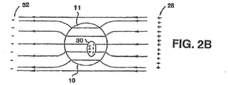
- FIGS. 2A and 2B schematically illustrate non-dividing cell 10 being subjected to an electric field produced by applying an alternating electric potential, at a relatively low frequency and at a relatively high frequency, respectively.
- Cell 10 includes intracellular organelles, e.g., a nucleus 30. Alternating electric potential is applied across electrodes 28 and 32 that can be attached externally to a patient at a predetermined region, e.g., in the vicinity of the tumor being treated.
- a conductive environment hereinafter referred to as a "volume conductor" consisting mostly of electrolytic inter-cellular liquid.
- the specific distribution of the electric field lines which is substantially consistent with the direction of current flow in this instance, depends on the geometry and the electric properties of the system components, e.g., the relative conductivities and dielectric constants of the system components, that can be frequency dependent. For low frequencies, e.g., frequencies lower than 10 KHz, the conductance properties of the components completely dominate the current flow and the field distribution, and the field distribution is generally as depicted in FIG. 2A . At higher frequencies, e.g., at frequencies of between 10 KHz and 1 MHz, the dielectric properties of the components becomes more significant and eventually dominate the field distribution, resulting in field distribution lines as depicted generally in FIG. 2B .
- the dielectric properties of the various components are not significant in determining and computing the field distribution. Therefore, as a first approximation, with regard to the electric field distribution, the system can be reasonably represented by the relative impedances of its various components. Using this approximation, the intercellular (i.e., extracellular) fluid and the intracellular fluid each has a relatively low impedance, while the cell membrane 11 has a relatively high impedance. Thus, under low frequency conditions, only a fraction of the electric field lines (or currents induced by the electric field) penetrate membrane 11 of the cell 10.
- the impedance of membrane 11 relative to the intercellular and intracellular fluids decreases, and thus, the fraction of currents penetrating the cells increases significantly. It should be noted that at very high frequencies, i.e., above 1 MHz, the membrane capacitance can short the membrane resistance and, therefore, the total membrane resistance can become negligible.
- the electric field lines penetrate cell 10 from a portion of the membrane 11 closest to one of the electrodes generating the current, e.g., closest to positive electrode 28 (also referred to herein as "source”).
- the current flow pattern across cell 10 is generally uniform because, under the above approximation, the field induced inside the cell is substantially homogeneous.
- the currents exit cell 10 through a portion of membrane 11 closest to the opposite electrode, e.g., negative electrode 32 (also referred to herein as "sink").
- field lines and current flow can depend on a number of factors, for example, on the frequency of the applied electric potential and on whether electrodes 28 and 32 are electrically insulated.
- insulated electrodes applying a DC or low frequency alternating voltage, there is practically no current flow along the lines of the electric field.
- the displacement currents are induced in the tissue due to charging and discharging of the electrode insulation and the cell membranes (which act as capacitors to a certain extent), and such currents follow the lines of the electric field.
- Fields generated by non-insulated electrodes in contrast, always generate some form of current flow, specifically, DC or low frequency alternating fields generate conductive current flow along the field lines, and high frequency alternating fields generate both conduction and displacement currents along the field lines.
- FIG. 2 schematically depicts the resulting field distribution in the system.
- the lines of force which also depict the lines of potential current flow across the cell volume mostly in parallel with the undistorted lines of force (the main direction of the electric field).
- the field inside the cells is mostly homogenous.
- the fraction of the field or current that penetrates the cells is determined by the cell membrane impedance value relative to that of the extracellular fluid. Since the equivalent electric circuit of the cell membrane is that of a resistor and capacitor in parallel, the impedance is a function of the frequency. The higher the frequency, the lower the impedance, the larger the fraction of penetrating current and the smaller the field distortion ( Rotshenker S. & Y. Palti, Changes in fraction of current penetrating an axon as a function of duration of stimulating pulse, J. Theor. Biol. 41; 401-407 (1973 ).
- Crithidia fusciculata which is a non-pathogenic insect intestinal parasite commonly used as a model organism for other pathogenic trypanosomatidae such as Leishmania.
- C. fusciculata cells have a relatively short generation time (2 hours), and are easy to grow in defined medium.
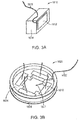
- FIG. 3A depicts the construction of the electrodes 1610 used in the experiment.
- Each electrode is 15 mm long and 5 mm high. It include an electrical conductor 1611 with its outer face coated with a layer of lead magnesium niobate-lead titanate (PMN-PT) ceramic insulation 1612, which has a high dielectric constant ( ⁇ > 5000) such that their capacitance was about 10 nF each.
- the rear of the conductor 1611 was insulated using a 5 mm layer 1614 of 353ND medical grade epoxy (Epoxy Technology, Billerica, MA, USA) and a wire 1613 is connected to the conductor 1611.
- PMN-PT lead magnesium niobate-lead titanate
- FIG. 3B depicts a test chamber that includes four electrodes 1610, arranged in pairs and positioned in a 50 mm Petri dish 1626.
- the electrodes were held in place by a polycarbonate holder 1624. Electric fields were generated in the test chamber by applying an AC voltage across one pair of opposing electrodes, then applying an AC voltage across the other pair of opposing electrodes, in an alternating sequence to produce electric fields in the medium that are oriented at 90° with respect to each other.
- the electrodes were placed 23 mm apart.
- the electrodes were completely insulated from the medium in the Petri dish by the ceramic insulation 1614 on the face of the electrode 1610, so the field is capacitively coupled through the layer 1614 into the target region.
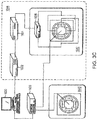
- FIG. 3C depicts a setup that was used to induce fields in the test chamber 1620.
- the output of a sinewave generator 1632 (Model 662, OR-X, Israel) is routed to an RF amplifier 1634 (75A250, AR worldwide, Souderton, PA, USA), and the output of the RF amplifier 1634 is routed to a field direction switching relay 1636 that either imposes the amplified sine wave between the upper and lower electrodes or between the right and left electrodes.
- the switching relay is configured to switch back and forth between those two states periodically, thereby switching the direction of the field at the desired interval.
- thermocouple (Omega, Stamford, CT) with its tip positioned at the center of the chamber 1620.
- the thermocouples were connected to a TC-08 Thermocouple Data Logger (Pico Technologies, UK) the output of which was connected to computer 1630.
- the chamber temperature was held at the desired value by computer feedback control of the amplitude of the waveform at the input of the power amplifier.
- the electric field intensities in the culture medium were measured using a shielded coaxial probe having two exposed tips fixed at a distance of 1 cm. The probe was connected, through a coaxial cable, to a 190B floating scope meter (Fluke, The Netherlands). Field intensities were measured at the end of each treatment by dipping the probe in the culture media, such that the two measuring points were in parallel with the lines of the electric field. Field intensities are expressed as peak-to-peak voltage per centimeter distance (V/cm).
- C. fusciculata parasites were grown in BHI media containing 0.0025% (w/v) Hemin (Sigma) and 0.8% (v/v) Penicillin ⁇ Streptomycin (03-031-1, Biological industries, Beit Haemek, Israel). Broth cultures of fresh parasites were grown in 3 ml of liquid medium at 28° C for 15 hours in an orbital shaker (200 RPM) and diluted in fresh BHI broth to a predetermined absorbance at 595 nm (Biowave Cell Density Meter, WPA, UK) which yielded the desired CFU per ml.
- a frequency dependence experiment was performed by applying electric fields at different frequencies to parasites in soft agar plates. Overnight parasite cultures were diluted in fresh BHI broth to an OD that corresponds to cell counts of 1 ⁇ 10 8 Colony Forming Units (CFU)/ml. The cultures were further diluted to a final concentration of 1 ⁇ 10 7 CFU in BHI containing 0.34% agar (Difco) that was melted and kept in 42° C warm bath prior to the addition of the parasites. The growth indicator-Alamar Blue (AbD Serotec, Oxford, UK) was added to a final concentration of 10%. The culture was stirred, and 7 ml were immediately poured into Petri plates containing the field chamber (see FIG. 3B ).
- CFU Colony Forming Units
- the plates were placed in a similar chamber without applying any fields, and the chambers were positioned in a pre-warmed temperature-controlled incubator configured to keep the temperature the same as the treated group.
- the chamber temperature reached 28.0 ⁇ 0.2° C within the first 15 minutes of the experiment in both the treated group and in the control group.
- the plates were placed inside a microplate reader (Infinite 200, Tecan, Austria) and the OD of the agar between the electrodes was determined at 550 and 595 nm.
- the amount of cells growth was calculated using the following formula: (OD 595nm of treated wells -OD 550nm of treated wells)-(OD 595nm of wells before treatment-OD 550nm of wells before treatment).
- the percentage of growth for each well was calculated by dividing the Alamar blue results of the experiments wells by that of the control.
- the results of the Alamar blue assay were correlated to the parasites number as determined by direct counts using a microscope.
- An intensity dependence experiment was performed by applying electric fields at different frequencies to parasites in liquid broth. Overnight parasite cultures were diluted in fresh BHI broth to an OD that corresponds to cell counts of 1 ⁇ 10 7 Colony Forming Units (CFU)/ml. The growth indicator-Alamar Blue (AbD Serotec, Oxford, UK) was added to a final concentration of 10%. Petri plates containing the field chamber (see FIG. 3B ) were filled with 7.5 ml of the diluted cultures, and placed inside a pre-cooled incubator set to 10° C (FOC 2251, Velp Scientifica).
- the plates were placed in a similar chamber without applying any fields, and the chambers were positioned in a pre-warmed temperature-controlled incubator configured to keep the temperature the same as the treated group.
- the field chamber temperature reached 28.0 ⁇ 0.2° C within the first 5 minutes of the experiment in both the treated group and in the control group.
- the bottom of the plate was scraped with a cell scraper and the cultures were stirred several times by up and down pipetting.
- Four aliquots of 250 ⁇ l were dispensed into a 96 MicroWells plate (Nunc) and the OD was determined spectrophotometrically with a microplate reader at 750 nm.
- the percentage of growth for each well was calculated by dividing the OD of the wells by that of the control: (OD 750nm of treated wells /OD 750nm of the control well) ⁇ 100.
- the percentage of growth was calculated as described above.
- the fields can be applied either alone or in combination with an anti parasite therapeutic agent.
- Practical application of fields for the inhibition of parasites either in humans, in animals, or ex vivo can be carried in various ways, including but not limited to: (a) applying the fields to a defined topical location by placing electrodes in the vicinity of the desired area (for example around the wound caused by Leishmaniasis); (b) applying the fields to an organ by placing the electrodes topically around the organ (for example, treatment of intestinal parasites by placing electrodes on the skin of the abdomen and back; (c) applying the fields by means of implanting the electrodes in the body interior; (d) applying the fields on blood parasites outside of the body during dialysis; (e) applying the fields in the parasites' growth/replication habitats; and (f) applying the fields to a water reservoir containing the target organism.
- Other potential uses include applying the fields to food or water to prevent the development of parasites, e.g., by placing electrodes inside
- the electrodes may be either placed on the patient's body or implanted in the patient's body.
- the MegaHertz-range frequencies that were found to be effective against parasites have virtually no impact on eukaryotic cells, so specificity is excellent, and adverse side effects are not a major concern.
- different frequencies may be applied to the target region, either simultaneously or sequentially, to target one or more types of parasites that may be present, as discussed above in connection with the other embodiments.
- the fields may also be applied in two or more different directions, as described below in connection with FIGS. 6A-C and 7 .
- the methods described herein may also be used in vitro, as according to the methods of the present invention, e.g., to combat parasites in food, on media, cell cultures, etc.
- the inventor has recognized that applying the field in different directions sequentially will increase the overall killing power, because the field orientation that is most effectively in killing dividing cells will be applied to a larger population of the dividing cells.
- a number of examples for applying the field in different directions are discussed below.
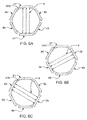
- FIGS. 6A, 6B and 6C show a set of 6 electrodes E1-E6, and how the direction of the field through the target tissue 1510 can be changed by applying the AC signal from the generator 1 (shown in FIG. 1 ) across different pairs of electrodes. For example, if the AC signal is applied across electrodes E1 and E4, the field lines F would be vertical (as shown in FIG. 6A ), and if the signal is applied across electrodes E2 and E5, or across electrodes E3 and E6, the field lines F would be diagonal (as shown in FIGS. 6B and 6C , respectively). Additional field directions can be obtained by applying the AC signal across other pairs of electrodes. For example, a roughly horizontal field could be obtained by applying the signal across electrodes E2 and E6.
- the AC signal is applied between the various pairs of electrodes sequentially.
- An example of this arrangement is to apply the AC signal across electrodes E1 and E4 for one second, then apply the AC signal across electrodes E2 and E5 for one second, and then apply the AC signal across electrodes E3 and E6 for one second. This three-part sequence is then repeated for the desired period of treatment. Because the efficacy in cell-destruction is strongly dependant on the cell's orientation, cycling the field between the different directions increases the chance that the field will be oriented in a direction that favors cell destruction at least part of the time.
- FIGS. 6A-C is just one of many possible arrangement of multiple electrodes, and many other configurations of three or more electrodes could be used based on the same principles.
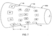
- FIG. 7 shows how the sequential application of signals across different sets of electrodes can be extended to three dimensions.
- a first array of electrodes A1-A9 is arranged around body part 1500, and a last array of electrodes N1-N9 is arranged around the body part 1500 a distance W away from the first array. Additional arrays of electrodes may optionally be added between the first array and the last array, but these additional arrays are not illustrated for clarity (so as not to obscure the electrodes A5-A9 and B5-B8 on the back of the body part 1500).
- the direction of the field through the target tissue can be changed by applying the AC signal from the generator 1 (shown in FIG. 1 ) across different pairs of electrodes.
- applying the AC signal between electrodes A2 and A7 would result in a field in a front-to-back direction between those two electrodes, and applying the AC signal between electrodes A5 and A9 would result in a roughly vertical field between those two electrodes.
- applying the AC signal across electrodes A2 and N7 would generate diagonal field lines in one direction through the body part 1500, and applying the AC signal across electrodes A2 and B7 would generate diagonal field lines in another direction through the body part.
- Using a three-dimensional array of electrodes also makes it possible to energize multiple pairs of electrodes simultaneously to induce fields in the desired directions. For example, if suitable switching is provided so that electrodes A2 through N2 are all connected to one terminal of the generator, and so that electrodes A7 through N7 are all connected to the other terminal of the generator, the resulting field would be a sheet that extends in a front-to-back direction for the entire width W. After the front-to-back field is maintained for a suitable duration (e.g., one second), the switching system (not shown) is reconfigured to connect electrodes A3 through N3 to one terminal of the generator, and electrodes A8 through N8 to the other terminal of the generator.
- a suitable duration e.g., one second
- the rotating sheet-shaped field may be added (sequentially in time) to the diagonal fields described above, to better target cells that are oriented along those diagonal axes.
- the signals may optionally be applied to combinations of electrodes simultaneously in order to form a desired resultant vector.
- a field that is rotated about the X axis by 20° with respect to the initial position can be obtained by switching electrodes A2 through N2 and A3 through N3 all to one terminal of the generator, and switching electrodes A7 through N7 and A8 through N8 all to the other terminal of the generator.
- Applying the signals to other combinations of electrodes will result in fields in other directions, as will be appreciated by persons skilled in the relevant arts. If appropriate computer control of the voltages is implemented, the field's direction can even be swept through space in a continuous (i.e., smooth) manner, as opposed to the stepwise manner described above.
- the present invention provides an effective, simple in vitro method of selectively destroying or inhibiting the growth of parasitic organisms, while non-dividing cells or organisms are left substantially unaffected by using the method on a sample containing both types of cells or organisms.
Description
- This invention concerns selective destruction of rapidly dividing cells in a localized area, and more particularly, selectively destroying target cells without destroying nearby non-target cells by applying an electric field with specific characteristics in vitro or to a region in a living patient.
- Eukaryotic parasites are the causative agents of many diseases such as Malaria, African sleeping sickness, Giardiasis, Leishmaniasis etc., and are responsible for deaths of millions of people around the globe. Parasites also infect millions of farm animals. Unfortunately, drug resistance and low therapeutic indexes limit the effectiveness of existing treatments.
- All living organisms proliferate by cell division, including cell cultures, microorganisms (such as bacteria, mycoplasma, yeast, protozoa, and other single-celled organisms), fungi, algae, plant cells, etc. Dividing cells of organisms can be destroyed, or their proliferation controlled, by methods that are based on the sensitivity of the dividing cells of these organisms to certain agents. For example, certain antibiotics stop the multiplication process of bacteria.
- The process of eukaryotic cell division is called "mitosis", which involves nice distinct phases (see Darnell et al., Molecular Cell Biology, New York: Scientific American Books, 1986, p. 149). During interphase, the cell replicates chromosomal DNA, which begins condensing in early prophase. At this point, centrioles (each cell contains 2) begin moving towards opposite poles of the cell. In middle prophase, each chromosome is composed of duplicate chromatids. Microtubular spindles radiate from regions adjacent to the centrioles, which are closer to their poles. By late prophase, the centrioles have reached the poles, and some spindle fibers extend to the center of the cell, while others extend from the poles to the chromatids. The cells then move into metaphase, when the chromosomes move toward the equator of the cell and align in the equatorial plane. Next is early anaphase, during which time daughter chromatids separate from each other at the equator by moving along the spindle fibers toward a centromere at opposite poles. The cell begins to elongate along the axis of the pole; the pole-to-pole spindles also elongate. Late anaphase occurs when the daughter chromosomes (as they are now called) each reach their respective opposite poles. At this point, cytokinesis begins as the cleavage furrow begins to form at the equator of the cell. In other words, late anaphase is the point at which pinching the cell membrane begins. During telophase, cytokinesis is nearly complete and spindles disappear. Only a relatively narrow membrane connection joins the two cytoplasms. Finally, the membranes separate fully, cytokinesis is complete and the cell returns to interphase.
- In meiosis, the cell undergoes a second division, involving separation of sister chromosomes to opposite poles of the cell along spindle fibers, followed by formation of a cleavage furrow and cell division. However, this division is not preceded by chromosome replication, yielding a haploid germ cell. Bacteria also divide by chromosome replication, followed by cell separation. However, since the daughter chromosomes separate by attachment to membrane components; there is no visible apparatus that contributes to cell division as in eukaryotic cells.
- It is well known that tumors, particularly malignant or cancerous tumors, grow uncontrollably compared to normal tissue. Such expedited growth enables tumors to occupy an ever-increasing space and to damage or destroy tissue adjacent thereto. Furthermore, certain cancers are characterized by an ability to transmit cancerous "seeds", including single cells or small cell clusters (metastases), to new locations where the metastatic cancer cells grow into additional tumors.
- The rapid growth of tumors, in general, and malignant tumors in particular, as described above, is the result of relatively frequent cell division or multiplication of these cells compared to normal tissue cells. The distinguishably frequent cell division of cancer cells is the basis for the effectiveness of existing cancer treatments, e.g., irradiation therapy and the use of various chemo-therapeutic agents. Such treatments are based on the fact that cells undergoing division are more sensitive to radiation and chemo-therapeutic agents than non-dividing cells. Because tumors cells divide much more frequently than normal cells, it is possible, to a certain extent, to selectively damage or destroy tumor cells by radiation therapy and/or chemotherapy. The actual sensitivity of cells to radiation, therapeutic agents, etc., is also dependent on specific characteristics of different types of normal or malignant cell types. Thus, unfortunately, the sensitivity of tumor cells is not sufficiently higher than that many types of normal tissues. This diminishes the ability to distinguish between tumor cells and normal cells, and therefore, existing cancer treatments typically cause significant damage to normal tissues, thus limiting the therapeutic effectiveness of such treatments. Furthermore, the inevitable damage to other tissue renders treatments very traumatic to the patients and, often, patients are unable to recover from a seemingly successful treatment. Also, certain types of tumors are not sensitive at all to existing methods of treatment.
- There are also other methods for destroying cells that do not rely on radiation therapy or chemotherapy alone. For example, ultrasonic and electrical methods for destroying tumor cells can be used in addition to or instead of conventional treatments. Electric fields and currents have been used for medical purposes for many years. The most common is the generation of electric currents in a human or animal body by application of an electric field by means of a pair of conductive electrodes between which a potential difference is maintained. These electric currents are used either to exert their specific effects, i.e., to stimulate excitable tissue, or to generate heat by flowing in the body since it acts as a resistor. Examples of the first type of application include the following: cardiac defibrillators, peripheral nerve and muscle stimulators, brain stimulators, etc. Currents are used for heating, for example, in devices for tumor ablation, ablation of malfunctioning cardiac or brain tissue, cauterization, relaxation of muscle rheumatic pain and other pain, etc.
- Another use of electric fields for medical purposes involves the utilization of high frequency oscillating fields transmitted from a source that emits an electric wave, such as an RF wave or a microwave source that is directed at the part of the body that is of interest (i.e., target). In these instances, there is no electric energy conduction between the source and the body; but rather, the energy is transmitted to the body by radiation or induction. More specifically, the electric energy generated by the source reaches the vicinity of the body via a conductor and is transmitted from it through air or some other electric insulating material to the human body.
- In a conventional electrical method, electrical current is delivered to a region of the target tissue using electrodes that are placed in contact with the body of the patient. The applied electrical current destroys substantially all cells in the vicinity of the target tissue. Thus, this type of electrical method does not discriminate between different types of cells within the target tissue and results in the destruction of both tumor cells and normal cells.
- Electric fields that can be used in medical applications can thus be separated generally into two different modes. In the first mode, the electric fields are applied to the body or tissues by means of conducting electrodes. These electric fields can be separated into two types, namely (1) steady fields or fields that change at relatively slow rates, and alternating fields of low frequencies that induce corresponding electric currents in the body or tissues, and (2) high frequency alternating fields (above 1 MHz) applied to the body by means of the conducting electrodes. In the second mode, the electric fields are high frequency alternating fields applied to the body by means of insulated electrodes.
- The first type of electric field is used, for example, to stimulate nerves and muscles, pace the heart, etc. In fact, such fields are used in nature to propagate signals in nerve and muscle fibers, central nervous system (CNS), heart, etc. The recording of such natural fields is the basis for the ECG, EEG, EMG, ERG, etc. The field strength in these applications, assuming a medium of homogenous electric properties, is simply the voltage applied to the stimulating/recording electrodes divided by the distance between them. These currents can be calculated by Ohm's law and can have dangerous stimulatory effects on the heart and CNS and can result in potentially harmful ion concentration changes. Also, if the currents are strong enough, they can cause excessive heating in the tissues. This heating can be calculated by the power dissipated in the tissue (the product of the voltage and the current).
- When such electric fields and currents are alternating, their stimulatory power, on nerve, muscle, etc., is an inverse function of the frequency. At frequencies above 1-10 KHz, the stimulation power of the fields approaches zero. This limitation is due to the fact that excitation induced by electric stimulation is normally mediated by membrane potential changes, the rate of which is limited by the RC properties (time constants on the order of 1 ms) of the membrane.
- Regardless of the frequency, when such current inducing fields are applied, they are associated with harmful side effects caused by currents. For example, one negative effect is the changes in ionic concentration in the various "compartments" within the system, and the harmful products of the electrolysis taking place at the electrodes, or the medium in which the tissues are imbedded. The changes in ion concentrations occur whenever the system includes two or more compartments between which the organism maintains ion concentration differences. For example, for most tissues, [Ca++] in the extracellular fluid is about 2×10⁻³ M, while in the cytoplasm of typical cells its concentration can be as low as 10-7 M. A current induced in such a system by a pair of electrodes, flows in part from the extracellular fluid into the cells and out again into the extracellular medium. About 2% of the current flowing into the cells is carried by the Ca++ ions. In contrast, because the concentration of intracellular Ca++ is much smaller, only a negligible fraction of the currents that exits the cells is carried by these ions. Thus, Ca++ ions accumulate in the cells such that their concentrations in the cells increases, while the concentration in the extracellular compartment may decrease. These effects are observed for both DC and alternating currents (AC). The rate of accumulation of the ions depends on the current intensity ion mobilities, membrane ion conductance, etc. An increase in [Ca++] is harmful to most cells and if sufficiently high will lead to the destruction of the cells. Similar considerations apply to other ions. In view of the above observations, long term current application to living organisms or tissues can result in significant damage. Another major problem that is associated with such electric fields, is due to the electrolysis process that takes place at the electrode surfaces. Here charges are transferred between the metal (electrons) and the electrolytic solution (ions) such that charged active radicals are formed. These can cause significant damage to organic molecules, especially macromolecules and thus damage the living cells and tissues.
- In contrast, when high frequency electric fields, above 1 MHz and usually in practice in the range of GHz, are induced in tissues by means of insulated electrodes, the situation is quite different. These type of fields generate only capacitive or displacement currents, rather than the conventional charge conducting currents. Under the effect of this type of field, living tissues behave mostly according to their dielectric properties rather than their electric conductive properties. Therefore, the dominant field effect is that due to dielectric losses and heating. Thus, it is widely accepted that in practice, the meaningful effects of such fields on living organisms, are only those due to their heating effects, i.e., due to dielectric losses.
- In
US-A-6,043,066 ('066) to Mangano, a method and device are presented which enable discrete objects having a conducting inner core, surrounded by a dielectric membrane to be selectively inactivated by electric fields via irreversible breakdown of their dielectric membrane. One potential application for this is in the selection and purging of certain biological cells in a suspension. According to the '066 patent, an electric field is applied for targeting selected cells to cause breakdown of the dielectric membranes of these tumor cells, while purportedly not adversely affecting other desired subpopulations of cells. The cells are selected on the basis of intrinsic or induced differences in a characteristic electroporation threshold. The differences in this threshold can depend upon a number of parameters, including the difference in cell size. - The method of the '066 patent is therefore based on the assumption that the electroporation threshold of tumor cells is sufficiently distinguishable from that of normal cells because of differences in cell size and differences in the dielectric properties of the cell membranes. Based upon this assumption, the larger size of many types of tumor cells makes these cells more susceptible to electroporation and thus, it may be possible to selectively damage only the larger tumor cell membranes by applying an appropriate electric field. One disadvantage of this method is that the ability to discriminate is highly dependent upon cell type, for example, the size difference between normal cells and tumor cells is significant only in certain types of cells. Another drawback of this method is that the voltages which are applied can damage some of the normal cells and may not damage all of the tumor cells because the differences in size and membrane dielectric properties are largely statistical and the actual cell geometries and dielectric properties can vary significantly.
-
US-A-2007/0184020 discloses a combination of radio waves with pharmacologically active substances. -
US-A-2004/0068296 discloses an apparatus and method for selectively destroying dividing cells by applying an electric field having certain prescribed characteristics using an apparatus that is configured to be complimentary to a specific body part. -
WO-A-2006/085150 concerns selective destruction of rapidly dividing cells in a localized area, and more particularly, selectively destroying dividing cells without destroying non-dividing cells by applying an electric field with specific characteristics to a target area in a living patient. - What is needed in the art and has heretofore not been available is an apparatus for destroying dividing cells, wherein the apparatus better discriminates between dividing cells, including single-celled organisms, and non-dividing cells and is capable of selectively destroying the dividing cells or organisms with substantially no effect on the non-dividing cells or organisms.
- In one aspect the present invention provides an in vitro method of selectively destroying or inhibiting the growth of parasites located within a target region according to
claim 1. - In another aspect the present invention provides a parasite treatment apparatus for selectively destroying or inhibiting the growth of parasites located within a target region of a patient according to claim 8.
- While they are dividing, cells are vulnerable to damage by AC electric fields that have specific frequency and field strength characteristics. The selective destruction of rapidly dividing cells can therefore be accomplished by imposing an AC electric field in a target region for extended periods of time. Some of the cells that divide while the field is applied will be damaged, but the cells that do not divide will not be harmed. This selectively damages rapidly dividing cells like parasites, but does not harm normal cells that are not dividing. Since the vulnerability of the dividing cells is strongly related to the alignment between the long axis of the dividing cells and the lines of force of the electric field, improved results are obtained by sequentially imposing the field in different directions.
- The present invention provides for treatment of parasites by selective destruction of parasites with substantially no effect on normal tissue cells. The present invention enables selective destruction of cells undergoing division in a way that is more effective and more accurate (e.g., more adaptable to be aimed at specific targets) than existing methods. Further, the present invention causes minimal damage, if any, to normal tissue and, thus, reduces or eliminates many side-effects associated with existing selective destruction methods, such as radiation therapy and chemotherapy. The selective destruction of dividing cells using the present invention does not depend on the sensitivity of the cells to chemical agents or radiation. Instead, the selective destruction of dividing cells is based on distinguishable geometrical characteristics of cells undergoing division, in comparison to non-dividing cells, regardless of the cell geometry of the type of cells being treated.
- It has been observed by the present inventor that, whilst different cells in their non-dividing state may have different shapes, e.g., spherical, ellipsoidal, cylindrical, "pancake-like", etc., the division process of practically all cells is characterized by development of a "cleavage furrow" in late anaphase and telophase. This cleavage furrow is a slow constriction of the cell membrane (between the two sets of daughter chromosomes) which appears microscopically as a growing cleft (e.g., a groove or notch) that gradually separates the cell into two new cells. During the division process, there is a transient period (telophase) during which the cell structure is basically that of two sub-cells interconnected by a narrow "bridge" formed of the cell material. The division process is completed when the "bridge" between the two sub-cells is broken. The selective destruction of parasites, using the present invention utilizes this unique geometrical feature of dividing cells.
- When a cell or a group of cells are under natural conditions or environment, i.e., part of a living tissue, they are disposed surrounded by a conductive environment consisting mostly of an electrolytic inter-cellular fluid and other cells that are composed mostly of an electrolytic intra-cellular liquid. When an electric field is induced in the living tissue, by applying an electric potential across the tissue, an electric field is formed in the tissue and the specific distribution and configuration of the electric field lines defines the direction of charge displacement, or paths of electric currents in the tissue, if currents are in fact induced in the tissue. The distribution and configuration of the electric field is dependent on various parameters of the tissue, including the geometry and the electric properties of the different tissue components, and the relative conductivities, capacities and dielectric constants (that may be frequency dependent) of the tissue components.
- The electric current flow pattern for cells undergoing division is very different and unique as compared to non-dividing cells. Such cells including first and second sub-cells, namely an "original" cell and a newly formed cell, that are connected by a cytoplasm "bridge" or "neck". The currents penetrate the first sub-cell through part of the membrane ("the current source pole"); however, they do not exit the first sub-cell through a portion of its membrane closer to the opposite pole ("the current sink pole"). Instead, the lines of current flow converge at the neck or cytoplasm bridge, whereby the density of the current flow lines is greatly increased. A corresponding, "mirror image", process that takes place in the second sub-cell, whereby the current flow lines diverge to a lower density configuration as they depart from the bridge, and finally exit the second sub-cell from a part of its membrane closes to the current sink.
- When a polarizable object is placed in a non-uniform converging or diverging field, electric forces act on it and pull it towards the higher density electric field lines. In the case of dividing cell, electric forces are exerted in the direction of the cytoplasm bridge between the two cells. Since all intercellular organelles and macromolecules are polarizable, they are all force towards the bridge between the two cells. The field polarity is irrelevant to the direction of the force and, therefore, an alternating electric having specific properties can be used to produce substantially the same effect. It will also be appreciated that the concentrated and inhomogeneous electric field present in or near the bridge or neck portion in itself exerts strong forces on charges and natural dipoles and can lead to the disruption of structures associated with these members.
- The movement of the cellular organelles towards the bridge disrupts the cell structure and results in increased pressure in the vicinity of the connecting bridge membrane. This pressure of the organelles on the bridge membrane is expected to break the bridge membrane and, thus, it is expected that the dividing cell will "explode" in response to this pressure.
- In one exemplary embodiment, the electric fields are applied by external insulated electrodes which are incorporated into an article of clothing and which are constructed so that the applied electric fields are of a local type that target a specific, localized area of tissue.
- According to another embodiment, the insulated electrodes are in the form of a probe or catheter etc., that enter the body through natural pathways, such as the urethra or vagina, or are configured to penetrate living tissue, until the insulated electrodes are positioned near the internal target area.
- Thus, the present invention utilizes electric fields that fall into a special intermediate category relative to previous high and low frequency applications in that the present electric fields are bio-effective fields that have no meaningful stimulatory effects and no thermal effects. Advantageously, when non-dividing cells are subjected to these electric fields, there is no effect on the cells; however, the situation is much different when dividing cells are subjected to the present electric fields. Thus, the generated electric fields target dividing cells, and do not target non-dividing cells that are found in healthy tissue surrounding the target area. Furthermore, since the present apparatus utilizes insulated electrodes, the above mentioned negative effects, obtained when conductive electrodes are used, i.e., ion concentration changes in the cells and the formation of harmful agents by electrolysis, do not occur with the present apparatus. This is because, in general, no actual transfer of charges takes place between the electrodes and the medium, and there is no charge flow in the medium where the currents are capacitive.
- The above, and other objects, features and advantages of the present apparatus will become apparent from the following description read in conjunction with the accompanying drawings, in which like reference numerals designate the same elements.
-
-
FIGS. 1A-1E are simplified, schematic, cross-sectional, illustrations of various stages of a cell division process; -
FIGS. 2A and2B are schematic illustrations of a non-dividing cell being subjected to an electric field; -
FIG. 3A depicts the construction of the electrodes used in an experiment on parasites; -
FIG. 3B depicts a test chamber used in an experiment on parasites; -
FIG. 3C depicts a setup that was used to induce fields in the test chamber; -
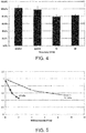
FIGS. 4 shows the effect of treating parasites with electric fields at different frequencies; -
FIGS. 5 shows the effect of treating parasites with electric fields at different filed strengths; -
FIGS.6-C show a configuration of electrodes that facilitates the application
of an electric field in different directions; and -
FIG. 7 shows a three-dimensional arrangement of electrodes about a body part that facilitates the application of an electric field in different directions. - Reference is made to
FIGS. 1A-1E which schematically illustrate various stages of a cell division process.FIG. 1A illustrates acell 10 at its normal geometry, which can be generally spherical (as illustrated in the drawings), ellipsoidal, cylindrical, "pancake-like" or any other cell geometry, as is known in the art.FIGS. 1B-1D illustratecell 10 during different stages of its division process, which results in the formation of twonew cells FIG. 1E . - As shown in
FIGS. 1B-1D , the division process ofcell 10 is characterized by a slowly growingcleft 12 which gradually separatescell 10 into two units, namely sub-cells 14 and 16, which eventually evolve intonew cells 18 and 20 (FIG. IE). A shown specifically in FIG. ID, the division process is characterized by a transient period during which the structure ofcell 10 is basically that of the two sub-cells 14 and 16 interconnected by a narrow "bridge" 22 containing cell material (cytoplasm surrounded by cell membrane). - Reference is now made to
FIGS. 2A and2B , which schematically illustratenon-dividing cell 10 being subjected to an electric field produced by applying an alternating electric potential, at a relatively low frequency and at a relatively high frequency, respectively.Cell 10 includes intracellular organelles, e.g., anucleus 30. Alternating electric potential is applied acrosselectrodes cell 10 is under natural conditions, i.e., part of a living tissue, it is disposed in a conductive environment (hereinafter referred to as a "volume conductor") consisting mostly of electrolytic inter-cellular liquid. When an electric potential is applied acrosselectrodes cell 10, while the rest of the field lines (or induced current) flow in the surrounding medium. The specific distribution of the electric field lines, which is substantially consistent with the direction of current flow in this instance, depends on the geometry and the electric properties of the system components, e.g., the relative conductivities and dielectric constants of the system components, that can be frequency dependent. For low frequencies, e.g., frequencies lower than 10 KHz, the conductance properties of the components completely dominate the current flow and the field distribution, and the field distribution is generally as depicted inFIG. 2A . At higher frequencies, e.g., at frequencies of between 10 KHz and 1 MHz, the dielectric properties of the components becomes more significant and eventually dominate the field distribution, resulting in field distribution lines as depicted generally inFIG. 2B . - For constant (i.e., DC) electric fields or relatively low frequency alternating electric fields, for example, frequencies under 10 KHz, the dielectric properties of the various components are not significant in determining and computing the field distribution. Therefore, as a first approximation, with regard to the electric field distribution, the system can be reasonably represented by the relative impedances of its various components. Using this approximation, the intercellular (i.e., extracellular) fluid and the intracellular fluid each has a relatively low impedance, while the
cell membrane 11 has a relatively high impedance. Thus, under low frequency conditions, only a fraction of the electric field lines (or currents induced by the electric field) penetratemembrane 11 of thecell 10. At relatively high frequencies (e.g., 10 KHz-1 MHz), in contrast, the impedance ofmembrane 11 relative to the intercellular and intracellular fluids decreases, and thus, the fraction of currents penetrating the cells increases significantly. It should be noted that at very high frequencies, i.e., above 1 MHz, the membrane capacitance can short the membrane resistance and, therefore, the total membrane resistance can become negligible. - In any of the embodiments described above, the electric field lines (or induced currents) penetrate
cell 10 from a portion of themembrane 11 closest to one of the electrodes generating the current, e.g., closest to positive electrode 28 (also referred to herein as "source"). The current flow pattern acrosscell 10 is generally uniform because, under the above approximation, the field induced inside the cell is substantially homogeneous. The currents exitcell 10 through a portion ofmembrane 11 closest to the opposite electrode, e.g., negative electrode 32 (also referred to herein as "sink"). - The distinction between field lines and current flow can depend on a number of factors, for example, on the frequency of the applied electric potential and on whether
electrodes -
FIG. 2 schematically depicts the resulting field distribution in the system. As illustrated, the lines of force, which also depict the lines of potential current flow across the cell volume mostly in parallel with the undistorted lines of force (the main direction of the electric field). In other words, the field inside the cells is mostly homogenous. In practice, the fraction of the field or current that penetrates the cells is determined by the cell membrane impedance value relative to that of the extracellular fluid. Since the equivalent electric circuit of the cell membrane is that of a resistor and capacitor in parallel, the impedance is a function of the frequency. The higher the frequency, the lower the impedance, the larger the fraction of penetrating current and the smaller the field distortion (Rotshenker S. & Y. Palti, Changes in fraction of current penetrating an axon as a function of duration of stimulating pulse, J. Theor. Biol. 41; 401-407 (1973). - Experiments were also performed on Crithidia fusciculata, which is a non-pathogenic insect intestinal parasite commonly used as a model organism for other pathogenic trypanosomatidae such as Leishmania. C. fusciculata cells have a relatively short generation time (2 hours), and are easy to grow in defined medium.
-
FIG. 3A depicts the construction of theelectrodes 1610 used in the experiment. Each electrode is 15 mm long and 5 mm high. It include an electrical conductor 1611 with its outer face coated with a layer of lead magnesium niobate-lead titanate (PMN-PT)ceramic insulation 1612, which has a high dielectric constant (ε > 5000) such that their capacitance was about 10 nF each. The rear of the conductor 1611 was insulated using a 5mm layer 1614 of 353ND medical grade epoxy (Epoxy Technology, Billerica, MA, USA) and awire 1613 is connected to the conductor 1611. Of course, it may be appropriate to vary the dimensions of the electrodes depending on the intended application. -
FIG. 3B depicts a test chamber that includes fourelectrodes 1610, arranged in pairs and positioned in a 50mm Petri dish 1626. The electrodes were held in place by apolycarbonate holder 1624. Electric fields were generated in the test chamber by applying an AC voltage across one pair of opposing electrodes, then applying an AC voltage across the other pair of opposing electrodes, in an alternating sequence to produce electric fields in the medium that are oriented at 90° with respect to each other. The electrodes were placed 23 mm apart. The electrodes were completely insulated from the medium in the Petri dish by theceramic insulation 1614 on the face of theelectrode 1610, so the field is capacitively coupled through thelayer 1614 into the target region. -
FIG. 3C depicts a setup that was used to induce fields in thetest chamber 1620. The output of a sinewave generator 1632 (Model 662, OR-X, Israel) is routed to an RF amplifier 1634 (75A250, AR worldwide, Souderton, PA, USA), and the output of theRF amplifier 1634 is routed to a fielddirection switching relay 1636 that either imposes the amplified sine wave between the upper and lower electrodes or between the right and left electrodes. The switching relay is configured to switch back and forth between those two states periodically, thereby switching the direction of the field at the desired interval. - Temperature was measured continuously using insulated T type thermocouple (Omega, Stamford, CT) with its tip positioned at the center of the
chamber 1620. The thermocouples were connected to a TC-08 Thermocouple Data Logger (Pico Technologies, UK) the output of which was connected tocomputer 1630. - As electric fields are associated with heat production, the chamber temperature was held at the desired value by computer feedback control of the amplitude of the waveform at the input of the power amplifier. The electric field intensities in the culture medium were measured using a shielded coaxial probe having two exposed tips fixed at a distance of 1 cm. The probe was connected, through a coaxial cable, to a 190B floating scope meter (Fluke, The Netherlands). Field intensities were measured at the end of each treatment by dipping the probe in the culture media, such that the two measuring points were in parallel with the lines of the electric field. Field intensities are expressed as peak-to-peak voltage per centimeter distance (V/cm).
- For the experiments described below, C. fusciculata parasites were grown in BHI media containing 0.0025% (w/v) Hemin (Sigma) and 0.8% (v/v) Penicillin\Streptomycin (03-031-1, Biological industries, Beit Haemek, Israel). Broth cultures of fresh parasites were grown in 3 ml of liquid medium at 28° C for 15 hours in an orbital shaker (200 RPM) and diluted in fresh BHI broth to a predetermined absorbance at 595 nm (Biowave Cell Density Meter, WPA, UK) which yielded the desired CFU per ml.
- A frequency dependence experiment was performed by applying electric fields at different frequencies to parasites in soft agar plates. Overnight parasite cultures were diluted in fresh BHI broth to an OD that corresponds to cell counts of 1×10⁸ Colony Forming Units (CFU)/ml. The cultures were further diluted to a final concentration of 1×10⁷ CFU in BHI containing 0.34% agar (Difco) that was melted and kept in 42° C warm bath prior to the addition of the parasites. The growth indicator-Alamar Blue (AbD Serotec, Oxford, UK) was added to a final concentration of 10%. The culture was stirred, and 7 ml were immediately poured into Petri plates containing the field chamber (see
FIG. 3B ). After the agar solidified, 1 ml of uninoculated BHI containing 10% Alamar blue was placed on top of the agar. The plates were placed inside a pre-cooled incubator set to 10° C (FOC 225I, Velp Scientifica). At each tested frequency, the fields were applied for 6 hours and the direction of the field was switched every 300 ms using the setup described above in connection withFIGS. 3A-C . The field strength was varied during the course of the test between 2 and 10 V/cm to maintain the desired temperature. - In the control group, the plates were placed in a similar chamber without applying any fields, and the chambers were positioned in a pre-warmed temperature-controlled incubator configured to keep the temperature the same as the treated group. The chamber temperature reached 28.0 ± 0.2° C within the first 15 minutes of the experiment in both the treated group and in the control group. At the end of treatment, the plates were placed inside a microplate reader (Infinite 200, Tecan, Austria) and the OD of the agar between the electrodes was determined at 550 and 595 nm. The amount of cells growth was calculated using the following formula: (OD595nm of treated wells -OD550nm of treated wells)-(OD595nm of wells before treatment-OD550nm of wells before treatment). The percentage of growth for each well was calculated by dividing the Alamar blue results of the experiments wells by that of the control. The results of the Alamar blue assay were correlated to the parasites number as determined by direct counts using a microscope.
- The frequency dependence of the fields' effect on the growth of C. fusciculata was tested between 100 kHz and 20 MHz. Higher field frequencies were not tested due to equipment limitations. The results, based on the Alamar blue assay, are depicted in
FIG. 4 and expressed in %. These results show that the maximum effectiveness occurred at 10 MHz. - An intensity dependence experiment was performed by applying electric fields at different frequencies to parasites in liquid broth. Overnight parasite cultures were diluted in fresh BHI broth to an OD that corresponds to cell counts of 1×10⁷ Colony Forming Units (CFU)/ml. The growth indicator-Alamar Blue (AbD Serotec, Oxford, UK) was added to a final concentration of 10%. Petri plates containing the field chamber (see
FIG. 3B ) were filled with 7.5 ml of the diluted cultures, and placed inside a pre-cooled incubator set to 10° C (FOC 2251, Velp Scientifica). Two aliquots of 250 µl from the experiment plates and from the control plates were dispensed into a 96 MicroWells plate (Nunclon™Δ, Nunc, Denmark) and the OD was determined spectrophotometrically with a microplate reader (Infinite 200, Tecan, Austria) at 550, 595 nm. At each tested intensity, the fields were applied for 17 hours and the direction of the field was switched every 300 ms using the setup described above in connection withFIGS. 3A-C . Since higher field strengths add more heat energy to the samples, the ambient temperature was varied to keep the sample temperature at the desired level. - In the control group, the plates were placed in a similar chamber without applying any fields, and the chambers were positioned in a pre-warmed temperature-controlled incubator configured to keep the temperature the same as the treated group. The field chamber temperature reached 28.0 ± 0.2° C within the first 5 minutes of the experiment in both the treated group and in the control group. At the end of treatment, the bottom of the plate was scraped with a cell scraper and the cultures were stirred several times by up and down pipetting. Four aliquots of 250 µl were dispensed into a 96 MicroWells plate (Nunc) and the OD was determined spectrophotometrically with a microplate reader at 750 nm. The optical densities (ODs) of the blanks, which consisted of uninoculated BHI, were subtracted from the ODs of the inoculated plates. The percentage of growth for each well was calculated by dividing the OD of the wells by that of the control: (OD750nm of treated wells /OD750nm of the control well) × 100. For the Alamar blue assay, the percentage of growth was calculated as described above.
- The results, based on the Alamar blue assay, are depicted in
FIG. 5 , expressed in %. These results show that the growth inhibition is field-intensity dependent, reaching a plateau at just over a 50% inhibition for 10 MHz fields with intensities around 2 V/cm. Similar inhibition was achieved when 0.1 MHz fields were applied, but the fields intensities required where much higher (9-10 V/cm). Note that the deviation from unity on the left-most data points inFIG. 5 is attributed to the fact that a very small field (0.01 V) was applied instead of zero field. - For in vivo applications, not according to the present invention, the fields can be applied either alone or in combination with an anti parasite therapeutic agent. Practical application of fields for the inhibition of parasites either in humans, in animals, or ex vivo can be carried in various ways, including but not limited to: (a) applying the fields to a defined topical location by placing electrodes in the vicinity of the desired area (for example around the wound caused by Leishmaniasis); (b) applying the fields to an organ by placing the electrodes topically around the organ (for example, treatment of intestinal parasites by placing electrodes on the skin of the abdomen and back; (c) applying the fields by means of implanting the electrodes in the body interior; (d) applying the fields on blood parasites outside of the body during dialysis; (e) applying the fields in the parasites' growth/replication habitats; and (f) applying the fields to a water reservoir containing the target organism. Other potential uses include applying the fields to food or water to prevent the development of parasites, e.g., by placing electrodes inside a water reservoir or container, and applying the fields to the water.
- Depending on the location of the target region within the body, the electrodes may be either placed on the patient's body or implanted in the patient's body. Note that the MegaHertz-range frequencies that were found to be effective against parasites have virtually no impact on eukaryotic cells, so specificity is excellent, and adverse side effects are not a major concern. Optionally, different frequencies may be applied to the target region, either simultaneously or sequentially, to target one or more types of parasites that may be present, as discussed above in connection with the other embodiments. The fields may also be applied in two or more different directions, as described below in connection with
FIGS. 6A-C and 7 . The methods described herein may also be used in vitro, as according to the methods of the present invention, e.g., to combat parasites in food, on media, cell cultures, etc. - The inventor has recognized that applying the field in different directions sequentially will increase the overall killing power, because the field orientation that is most effectively in killing dividing cells will be applied to a larger population of the dividing cells. A number of examples for applying the field in different directions are discussed below.
-
FIGS. 6A, 6B and 6C show a set of 6 electrodes E1-E6, and how the direction of the field through thetarget tissue 1510 can be changed by applying the AC signal from the generator 1 (shown inFIG. 1 ) across different pairs of electrodes. For example, if the AC signal is applied across electrodes E1 and E4, the field lines F would be vertical (as shown inFIG. 6A ), and if the signal is applied across electrodes E2 and E5, or across electrodes E3 and E6, the field lines F would be diagonal (as shown inFIGS. 6B and 6C , respectively). Additional field directions can be obtained by applying the AC signal across other pairs of electrodes. For example, a roughly horizontal field could be obtained by applying the signal across electrodes E2 and E6. - In one embodiment, the AC signal is applied between the various pairs of electrodes sequentially. An example of this arrangement is to apply the AC signal across electrodes E1 and E4 for one second, then apply the AC signal across electrodes E2 and E5 for one second, and then apply the AC signal across electrodes E3 and E6 for one second. This three-part sequence is then repeated for the desired period of treatment. Because the efficacy in cell-destruction is strongly dependant on the cell's orientation, cycling the field between the different directions increases the chance that the field will be oriented in a direction that favors cell destruction at least part of the time.
- Of course, the 6 electrode configuration shown in
FIGS. 6A-C is just one of many possible arrangement of multiple electrodes, and many other configurations of three or more electrodes could be used based on the same principles. - Application of the field in different directions sequentially is not limited to two dimensional embodiments, and
FIG. 7 shows how the sequential application of signals across different sets of electrodes can be extended to three dimensions. A first array of electrodes A1-A9 is arranged aroundbody part 1500, and a last array of electrodes N1-N9 is arranged around the body part 1500 a distance W away from the first array. Additional arrays of electrodes may optionally be added between the first array and the last array, but these additional arrays are not illustrated for clarity (so as not to obscure the electrodes A5-A9 and B5-B8 on the back of the body part 1500). - As in the
FIG. 6 embodiment, the direction of the field through the target tissue can be changed by applying the AC signal from the generator 1 (shown inFIG. 1 ) across different pairs of electrodes. For example, applying the AC signal between electrodes A2 and A7 would result in a field in a front-to-back direction between those two electrodes, and applying the AC signal between electrodes A5 and A9 would result in a roughly vertical field between those two electrodes. Similarly, applying the AC signal across electrodes A2 and N7 would generate diagonal field lines in one direction through thebody part 1500, and applying the AC signal across electrodes A2 and B7 would generate diagonal field lines in another direction through the body part. - Using a three-dimensional array of electrodes also makes it possible to energize multiple pairs of electrodes simultaneously to induce fields in the desired directions. For example, if suitable switching is provided so that electrodes A2 through N2 are all connected to one terminal of the generator, and so that electrodes A7 through N7 are all connected to the other terminal of the generator, the resulting field would be a sheet that extends in a front-to-back direction for the entire width W. After the front-to-back field is maintained for a suitable duration (e.g., one second), the switching system (not shown) is reconfigured to connect electrodes A3 through N3 to one terminal of the generator, and electrodes A8 through N8 to the other terminal of the generator. This results in a sheet-shaped field that is rotated about the Z axis by about 40° with respect to the initial field direction. After the field is maintained in this direction for a suitable duration (e.g., one second), the next set of electrodes is activated to rotate the field an additional 40° to its next position. This continues until the field returns to its initial position, at which point the whole process is repeated.
- Optionally, the rotating sheet-shaped field may be added (sequentially in time) to the diagonal fields described above, to better target cells that are oriented along those diagonal axes.
- Because the electric field is a vector, the signals may optionally be applied to combinations of electrodes simultaneously in order to form a desired resultant vector. For example, a field that is rotated about the X axis by 20° with respect to the initial position can be obtained by switching electrodes A2 through N2 and A3 through N3 all to one terminal of the generator, and switching electrodes A7 through N7 and A8 through N8 all to the other terminal of the generator. Applying the signals to other combinations of electrodes will result in fields in other directions, as will be appreciated by persons skilled in the relevant arts. If appropriate computer control of the voltages is implemented, the field's direction can even be swept through space in a continuous (i.e., smooth) manner, as opposed to the stepwise manner described above.
- Thus, the present invention provides an effective, simple in vitro method of selectively destroying or inhibiting the growth of parasitic organisms, while non-dividing cells or organisms are left substantially unaffected by using the method on a sample containing both types of cells or organisms.
- While the invention has been particularly shown and described with reference to preferred embodiments thereof, it will be understood by those skilled in the art that various changes in form and details can be made without departing from the scope of the invention.
Claims (17)
- An in vitro method of selectively destroying or inhibiting the growth of parasites located within a target region (1620), comprising the step of:capacitively coupling an AC electric field into the target region (1620);wherein the strength of the electric field in at least a portion of the target region (1620) is between 0.5 V/cm and 10 V/cm, wherein the electric field is configured to disrupt the parasites located within the target region (1620) and to leave non-dividing cells located within the target region (1620) substantially unharmed;characterized in that:the frequency of the electric field is between 1.5 MHz and 20 MHz; andthe coupling step is repeated until a plateau at over 50% in the growth inhibition of the parasites within the target region (1620) is reached.
- The method of claim 1, wherein the frequency of the electric field is between 10 MHz and 20 MHz, optionally 10 MHz.
- The method of claim 1, wherein the electric field has a first orientation during a first interval of time and a second orientation during a second interval of time, and at least a portion of the first interval of time and the second interval of time are mutually exclusive, optionally the first orientation is generally perpendicular to the second orientation, and optionally the first interval of time is 300 mS and the second interval of time is 300 mS.
- The method of claim 1, further comprising the step of:
delivering a therapeutic agent to the target region (1620) so that a dose of the therapeutic agent is present in the target region (1620) while the coupling step is performed. - The method of claim 1, wherein the strength of the electric field is between 2 V/cm and 10 V/cm, optionally 2 V/cm.
- The method of claim 1, further comprising the step of:measuring temperature at the target region (1620); andholding the temperature at the target region (1620) at a desired value by computer feedback control based on the measured temperature at the target region (1620).
- The method of claim 1, for the treatment of waterborne parasites.
- A parasite treatment apparatus for selectively destroying or inhibiting the growth of parasites located within a target region (1620) of a patient, the apparatus comprising:a first pair of insulated electrodes (1610), each having a surface which capacitively couples an electric field into the target region (1620); andan AC voltage source (1632, 1634) operatively connected to the electrodes (1610);wherein the AC voltage source (1632, 1634) and the electrodes (1610) are configured so that, when the electrodes (1610) are placed against the target region (1620) and the AC voltage source (1632, 1634) is activated, an AC electric field is capacitively coupled into the target region (1620) via the electrodes (1610);wherein the strength of the electric field in at least a portion of the target region (1620) is between 0.5 V/cm and 10 V/cm, wherein the electric field is configured to disrupt the parasites located within the target region (1620) and to leave non-dividing cells located within the target region (1620) substantially unharmed:
characterized in that:
the frequency of the electric field is between 1.5 MHz and 20 MHz. - The apparatus of claim 8, wherein the frequency of the electric field is between 10 MHz and 20 MHz, optionally 10 MHz.
- The apparatus of claim 8, wherein the strength of the electric field is between 2 V/cm and 10 V/cm, optionally 2 V/cm.
- The apparatus of claim 8, wherein the surface of each of the electrodes (1610) is insulated from the AC voltage source (1632, 1634) by a dielectric coating.
- The apparatus of claim 8, further comprising:a second pair of insulated electrodes (1610), each having a surface which capacitively couples an electric field into the target region (1620); anda switching mechanism (1636) that alternately applies the output of the AC voltage source (1632, 1634) to either (a) the first pair of electrodes (1610) or (b) the second pair of electrodes (1610), optionally the first pair of electrodes (1610) is oriented with respect to the second pair of electrodes (1610) so that the electric field that is coupled into the target region (1620) when the AC voltage is applied to the first pair of electrodes (1610) is roughly perpendicular to the electric field that is coupled into the target region (1620) when the AC voltage is applied to the second pair of electrodes (1610), optionally the electric field has a first orientation during a first interval of time and a second orientation during a second interval of time, wherein at least a portion of the first interval of time and the second interval of time are mutually exclusive, and optionally the first interval of time is 300 mS and the second interval of time is 300 mS.
- The apparatus of claim 8, further comprising:temperature measurement means for measuring temperature at the target region (1620); anda computer feedback controller for holding the temperature at the target region (1620) at a desired value by computer feedback control based on the measured temperature at the target region (1620).
- The apparatus of claim 8, in combination with a dose of a therapeutic agent for delivery to the target region (1620).
- The apparatus of claim 8, wherein the target region (1620) is within a patient's body.
- The apparatus of claim 8, for the treatment of blood parasites during dialysis.
- The apparatus of claim 8, for the treatment of waterborne parasites, wherein the electrodes (1610) are placed inside a water reservoir or container.
Applications Claiming Priority (2)
| Application Number | Priority Date | Filing Date | Title |
|---|---|---|---|
| US95571907P | 2007-08-14 | 2007-08-14 | |
| PCT/IB2008/002134 WO2009022225A1 (en) | 2007-08-14 | 2008-08-13 | Treating parasites with electric fields |
Publications (2)
| Publication Number | Publication Date |
|---|---|
| EP2183024A1 EP2183024A1 (en) | 2010-05-12 |
| EP2183024B1 true EP2183024B1 (en) | 2019-05-15 |
Family
ID=40219471
Family Applications (1)
| Application Number | Title | Priority Date | Filing Date |
|---|---|---|---|
| EP08789083.6A Active EP2183024B1 (en) | 2007-08-14 | 2008-08-13 | Treating parasites with electric fields |
Country Status (9)
| Country | Link |
|---|---|
| US (1) | US7890183B2 (en) |
| EP (1) | EP2183024B1 (en) |
| JP (1) | JP5485153B2 (en) |
| CN (1) | CN101820947A (en) |
| CA (1) | CA2696352C (en) |
| DK (1) | DK2183024T3 (en) |
| ES (1) | ES2739384T3 (en) |
| PT (1) | PT2183024T (en) |
| WO (1) | WO2009022225A1 (en) |
Families Citing this family (68)
| Publication number | Priority date | Publication date | Assignee | Title |
|---|---|---|---|---|
| US8447395B2 (en) * | 2000-02-17 | 2013-05-21 | Novocure Ltd | Treating bacteria with electric fields |
| US8175698B2 (en) * | 2000-02-17 | 2012-05-08 | Novocure Ltd. | Treating bacteria with electric fields |
| EP2335776A1 (en) | 2000-02-17 | 2011-06-22 | Yoram Palti | Method and apparatus for destroying dividing cells |
| DE10260149A1 (en) | 2002-12-20 | 2004-07-01 | BSH Bosch und Siemens Hausgeräte GmbH | Device for determining the conductivity of laundry, clothes dryer and method for preventing layer formation on electrodes |
| CA2563817C (en) | 2004-04-23 | 2018-07-10 | Yoram Palti | Treating a tumor or the like with electric fields at different frequencies |
| PT2364748T (en) * | 2004-12-07 | 2018-03-26 | Novocure Ltd | Electrodes for applying an electric field in-vivo over an extended period of time |
| DK1933937T3 (en) * | 2005-10-03 | 2015-04-07 | Novocure Ltd | OPTIMIZATION OF THE CHARACTERISTICS OF AN ELECTRIC FIELD FOR ENHANCING FIELD EFFECT ON proliferating cells |
| US8019414B2 (en) * | 2006-04-05 | 2011-09-13 | Novocure Ltd. | Treating cancer using electromagnetic fields in combination with other treatment regimens |
| US8892199B2 (en) * | 2006-10-18 | 2014-11-18 | Buckeye Pharmaceuticals | Chemical compound delivery device and method |
| EP3231480A1 (en) * | 2007-03-06 | 2017-10-18 | Novocure Ltd. | Treating cancer using electromagnetic fields in combination with photodynamic therapy |
| WO2009022225A1 (en) | 2007-08-14 | 2009-02-19 | Novocure Ltd. | Treating parasites with electric fields |
| US8992593B2 (en) * | 2007-12-26 | 2015-03-31 | Cook Medical Technologies Llc | Apparatus and methods for deployment of a modular stent-graft system |
| US8684901B1 (en) | 2010-11-22 | 2014-04-01 | Jacob Zabara | Electromagnetic radiation treatment for cancer and pathological genetic regulations |
| US9233257B1 (en) | 2010-11-22 | 2016-01-12 | Jacob Zabara | Electromagnetic radiation treatment |
| AU2012364909B2 (en) | 2011-02-15 | 2016-11-24 | Hemosonics, Llc | Characterization of blood hemostasis and oxygen transport parameters |
| EP2522389A3 (en) * | 2011-05-13 | 2014-08-27 | Sergio Lara Pereira Monteiro | Animal and plant cell electric stimulator with randomized spatial distribution of electrodes for both current injection and for electric field shaping |
| US9486625B2 (en) | 2011-08-08 | 2016-11-08 | Medamp Electronics, Llc | Method for treating benign prostate hyperplasia |
| JP2014522714A (en) | 2011-08-08 | 2014-09-08 | ルース,リチャード,ビー. | Method and apparatus for treating cancer |
| DE102012015482A1 (en) * | 2012-08-07 | 2014-02-13 | Cinogy Gmbh | Electrode arrangement for a disabled plasma |
| DE102012025052A1 (en) * | 2012-12-20 | 2014-06-26 | Fresenius Medical Care Deutschland Gmbh | Hämodiafiltrationsverfahren |
| US9655669B2 (en) | 2013-05-06 | 2017-05-23 | Novocure Limited | Optimizing treatment using TTFields by changing the frequency during the course of long term tumor treatment |
| US10779875B2 (en) | 2013-05-06 | 2020-09-22 | Novocure Gmbh | Optimizing treatment using TTfields by changing the frequency during the course of long term tumor treatment |
| US20190117963A1 (en) * | 2014-07-25 | 2019-04-25 | Loyalty Based Innovations, LLC | Apparatus and method for treating multiple tumors in patients with metastatic disease by electric fields |
| US9726647B2 (en) | 2015-03-17 | 2017-08-08 | Hemosonics, Llc | Determining mechanical properties via ultrasound-induced resonance |
| US10188851B2 (en) | 2015-10-28 | 2019-01-29 | Novocure Limited | TTField treatment with optimization of electrode positions on the head based on MRI-based conductivity measurements |
| US10821283B2 (en) | 2016-04-04 | 2020-11-03 | Novocure Gmbh | Reducing motility of cancer cells using tumor treating fields (TTFields) |
| WO2018097185A1 (en) | 2016-11-24 | 2018-05-31 | 公立大学法人横浜市立大学 | Cancer treatment apparatus |
| CA3049949A1 (en) | 2017-01-19 | 2018-07-26 | Novocure Limited | System for viewing cell cultures under a microscope whilst applying tumor treating fields |
| EP3579920A1 (en) * | 2017-02-07 | 2019-12-18 | Santi Tofani | Apparatus for treating pathological cells |
| US11338135B2 (en) | 2017-10-23 | 2022-05-24 | Cardiac Pacemakers, Inc. | Medical devices for cancer therapy with electric field shaping elements |
| US10953209B2 (en) | 2018-03-28 | 2021-03-23 | Board Of Regents Of The University Of Texas System | Treating tumors using TTFields combined with a PARP inhibitor |
| EP3773726A1 (en) | 2018-04-09 | 2021-02-17 | Moshe Giladi | Treating tumors with ttfields and an aurora kinase inhibitor |
| PL3775956T3 (en) | 2018-04-10 | 2022-10-10 | Novocure Gmbh | Low frequency (< 1 mhz) ac conductivity estimates derived from two mri images having different repetition times |
| EP3900774B1 (en) | 2018-07-03 | 2022-10-05 | The Board of Trustees of the Leland Stanford Junior University | Using alternating electric fields to increase cell membrane permeability |
| SG11202012564SA (en) | 2018-07-10 | 2021-01-28 | Novocure Gmbh | Inhibiting viral infection using alternating electric fields |
| US11179322B2 (en) | 2018-07-10 | 2021-11-23 | Novocure Gmbh | Methods and compositions for treating tumors with TTFields and sorafenib |
| KR102607603B1 (en) | 2018-07-18 | 2023-11-29 | 노보큐어 게엠베하 | Use of power loss density and related measurements to quantify tumor treatment field capacity |
| CA3100817A1 (en) | 2018-08-23 | 2020-02-27 | Carsten Hagemann | Using alternating electric fields to increase permeability of the blood brain barrier |
| US11160977B2 (en) | 2018-09-04 | 2021-11-02 | Novocure Gmbh | Delivering tumor treating fields (TTFields) to the infratentorial brain |
| WO2020049482A1 (en) | 2018-09-07 | 2020-03-12 | Yaniv Alon | Treating autoimmune diseases using an alternating electric field to reduce the proliferation of t-cells |
| EP3878505B1 (en) | 2018-10-15 | 2023-05-24 | Novocure GmbH | Generating tumor treating fields (ttfields) with high uniformity throughout the brain |
| US11369790B2 (en) * | 2018-10-25 | 2022-06-28 | Novocure Gmbh | Delivering alternating electric fields (e.g., TTFields) to a subject's spinal anatomy |
| EP3922301B1 (en) | 2018-11-19 | 2024-02-21 | Novocure GmbH | Arrays for delivering tumor treating fields (ttfields) with selectively addressable sub-elements |
| EP4019082B1 (en) | 2018-11-29 | 2024-04-03 | Novocure GmbH | Enhanced-flexibility transducer arrays for delivering ttfields (tumor treating fields) |
| CN113330485A (en) | 2019-01-08 | 2021-08-31 | 诺沃库勒有限责任公司 | Assessing the quality of segmenting an image into different types of tissue for planning a treatment using a tumor treatment field (TTField) |
| US11344740B2 (en) | 2019-02-07 | 2022-05-31 | Asha Medical, Inc. | System and methods for treating cancer cells with alternating polarity magnetic fields |
| US11027143B2 (en) | 2020-02-06 | 2021-06-08 | Vivek K. Sharma | System and methods for treating cancer cells with alternating polarity magnetic fields |
| CN113692302A (en) | 2019-02-07 | 2021-11-23 | V·K·沙玛 | System and method for treating cancer cells with alternating polarity magnetic fields |
| CA3127276A1 (en) | 2019-02-26 | 2020-09-03 | Novocure Gmbh | Determining a frequency for ttfields treatment based on an electrical characteristic of targeted cancer cells |
| CN113453638A (en) | 2019-02-27 | 2021-09-28 | 诺沃库勒有限责任公司 | Delivering tumor therapy fields (TTfields) using an implantable transducer array |
| FR3093645B1 (en) * | 2019-03-15 | 2021-04-02 | Univ Montpellier | Microfluidic chip to attract and destroy a specific biological element |
| CN113613651A (en) | 2019-03-29 | 2021-11-05 | 诺沃库勒有限责任公司 | Method of restoring sensitivity to TTField in TTField-resistant cancer cells using PTGER3 inhibitors |
| PL3960232T3 (en) | 2019-04-17 | 2023-05-15 | Novocure Gmbh | Uploading data from an isolated system without compromising isolation |
| US11420049B2 (en) | 2019-04-22 | 2022-08-23 | Boston Scientific Scimed, Inc. | Systems for administering electrical stimulation to treat cancer |
| CN113727753A (en) | 2019-04-22 | 2021-11-30 | 波士顿科学国际有限公司 | Electrical stimulation device for cancer treatment |
| US11712561B2 (en) | 2019-04-23 | 2023-08-01 | Boston Scientific Scimed, Inc. | Electrical stimulation with thermal treatment or thermal monitoring |
| CN113747936A (en) | 2019-04-23 | 2021-12-03 | 波士顿科学国际有限公司 | Electrode for electrical stimulation to treat cancer |
| WO2020219517A2 (en) | 2019-04-23 | 2020-10-29 | Boston Scientific Scimed, Inc. | Electrical stimulation for cancer treatment with internal and external electrodes |
| EP4003492A1 (en) | 2019-07-31 | 2022-06-01 | Novocure GmbH | Applying tumor treating fields (ttfields) via electrodes embedded into skull implants |
| JP2022545794A (en) | 2019-08-30 | 2022-10-31 | ノボキュア ゲーエムベーハー | Application of tumor therapeutic fields (TTFields) to the neck |
| KR20220123079A (en) | 2019-12-31 | 2022-09-05 | 노보큐어 게엠베하 | Arrays delivering a tumor treatment field (tumor treatment field) with individually accessible electrode elements and temperature sensors |
| EP4054705A2 (en) | 2019-12-31 | 2022-09-14 | Novocure GmbH | High voltage, high efficiency sine wave generator that prevents spikes during amplitude adjustments and switching of channels |
| CN115515674A (en) | 2020-02-24 | 2022-12-23 | 波士顿科学国际有限公司 | Systems and methods for treating pancreatic cancer |
| WO2021257967A1 (en) | 2020-06-19 | 2021-12-23 | The Methodist Hospital Dba Houston Methodist Hospital | Method and apparatus for oncomagnetic treatment |
| US11818943B2 (en) | 2020-06-25 | 2023-11-14 | Novocure Gmbh | Fabricating organic light emitting diodes (OLEDs) using tubulin |
| DE102021102884A1 (en) * | 2021-02-08 | 2022-08-11 | Elea Vertriebs- Und Vermarktungsgesellschaft Mbh | Process for paralyzing parasites in food, in particular in a foodstuff or animal feed and foodstuff made therewith with paralyzed parasites |
| US20230173265A1 (en) * | 2021-12-10 | 2023-06-08 | Novocure Gmbh | Garment providing a biasing force on a transducer array |
| CN116020054B (en) * | 2023-02-24 | 2023-12-08 | 北京微脊医疗科技有限公司 | Implantable electric field therapeutic device |
Citations (1)
| Publication number | Priority date | Publication date | Assignee | Title |
|---|---|---|---|---|
| WO2006085150A2 (en) * | 2004-12-27 | 2006-08-17 | Standen Ltd. | Treating a tumor or the like with electric fields at different orientations |
Family Cites Families (67)
| Publication number | Priority date | Publication date | Assignee | Title |
|---|---|---|---|---|
| FR446660A (en) | 1911-09-02 | 1912-12-12 | Gottlieb Schuettel | Device for continuous ring looms for mounting the sliders on the rings |
| BE794566A (en) | 1972-01-28 | 1973-07-26 | Esb Inc | BIOELECTROCHEMICAL REGENERATOR AND STIMULATOR AND IN VIVO APPLICATION METHODS OF ELECTRIC ENERGY TO CELLS AND TISSUES. |
| US3991770A (en) | 1974-01-24 | 1976-11-16 | Leveen Harry H | Method for treating benign and malignant tumors utilizing radio frequency, electromagnetic radiation |
| US4016886A (en) | 1974-11-26 | 1977-04-12 | The United States Of America As Represented By The United States Energy Research And Development Administration | Method for localizing heating in tumor tissue |
| US4121592A (en) | 1975-08-04 | 1978-10-24 | Critical Systems, Inc. | Apparatus for heating tissue |
| DE2907013A1 (en) | 1978-02-24 | 1979-08-30 | American Med Syst | METHOD AND DEVICE FOR AIDING THE HEALING OF INJURED BONE CARTILES AND TISSUES IN THE FACIAL AREA |
| DE2813068A1 (en) | 1978-03-25 | 1979-10-04 | Philips Patentverwaltung | METHOD AND DEVICE FOR DETERMINING INTERNAL BODY STRUCTURES |
| GB2043453A (en) | 1979-02-22 | 1980-10-08 | Electrochem Tech Corp | Improvements in or relating to an electrode |
| US4472506A (en) | 1981-01-13 | 1984-09-18 | Liburdy Robert P | Method for determining cell membrane dielectric breakdown |
| US4467809A (en) | 1982-09-17 | 1984-08-28 | Biolectron, Inc. | Method for non-invasive electrical stimulation of epiphyseal plate growth |
| US4622952A (en) | 1983-01-13 | 1986-11-18 | Gordon Robert T | Cancer treatment method |
| CA1244889A (en) | 1983-01-24 | 1988-11-15 | Kureha Chemical Ind Co Ltd | Device for hyperthermia |
| DE3323415C2 (en) | 1983-06-29 | 1985-04-25 | Kernforschungsanlage Jülich GmbH, 5170 Jülich | Use of a method and a device for the determination of cells secreting cell constituents |
| SE455920B (en) | 1986-01-29 | 1988-08-22 | Hans Wiksell | TUMOR HYPERTERMY TREATMENT DEVICE |
| US4923814A (en) | 1986-05-09 | 1990-05-08 | Electropore, Inc. | High speed, high power apparatus for vesicle prealignment, poration, loading and fusion in uniform electric fields and method therefor |
| CN86103803B (en) | 1986-06-05 | 1987-11-18 | 北京信息工程学院 | Therapeutic equipment using electrostatic field |
| US4822470A (en) | 1987-10-09 | 1989-04-18 | Baylor College Of Medicine | Method of and apparatus for cell poration and cell fusion using radiofrequency electrical pulses |
| US4936303A (en) | 1987-11-20 | 1990-06-26 | Ultrathermics | Ultrasonic heating apparatus and method |
| JPH0629196B2 (en) | 1987-12-01 | 1994-04-20 | 甲子郎 梅村 | Physiological action enhancer for tumor treatment by ultrasound |
| US5389069A (en) | 1988-01-21 | 1995-02-14 | Massachusetts Institute Of Technology | Method and apparatus for in vivo electroporation of remote cells and tissue |
| FR2627987B3 (en) | 1988-03-04 | 1990-02-02 | Indiba Sa | ELECTRONIC APPARATUS FOR MEDICAL AND COSMETIC THERAPY |
| US5158071A (en) | 1988-07-01 | 1992-10-27 | Hitachi, Ltd. | Ultrasonic apparatus for therapeutical use |
| GB8904998D0 (en) | 1989-03-04 | 1989-04-19 | Matthews Tony | Anaesthetising apparatus |
| US5099756A (en) | 1989-06-01 | 1992-03-31 | Harry H. Leveen | Radio frequency thermotherapy |
| US5441746A (en) | 1989-12-22 | 1995-08-15 | Molecular Bioquest, Inc. | Electromagnetic wave absorbing, surface modified magnetic particles for use in medical applications, and their method of production |
| US5236410A (en) | 1990-08-02 | 1993-08-17 | Ferrotherm International, Inc. | Tumor treatment method |
| CA2109084C (en) | 1991-05-03 | 2004-02-24 | John William Fisher Costerton | Biofilm reduction method |
| US5441532A (en) | 1991-06-26 | 1995-08-15 | Massachusetts Institute Of Technology | Adaptive focusing and nulling hyperthermia annular and monopole phased array applicators |
| US5468223A (en) | 1992-11-30 | 1995-11-21 | C.N.R.S. Paris | Electrochemotherapy |
| US5386837A (en) | 1993-02-01 | 1995-02-07 | Mmtc, Inc. | Method for enhancing delivery of chemotherapy employing high-frequency force fields |
| FR2703253B1 (en) | 1993-03-30 | 1995-06-23 | Centre Nat Rech Scient | APPLICATOR OF ELECTRIC PULSES FOR TREATING BIOLOGICAL TISSUES. |
| IL108775A (en) | 1994-02-25 | 2003-09-17 | Univ Ramot | Method for efficient incorporation of molecules into cells |
| US5704355A (en) | 1994-07-01 | 1998-01-06 | Bridges; Jack E. | Non-invasive system for breast cancer detection |
| AU6639596A (en) | 1995-07-28 | 1997-02-26 | James R. Gray | Use of a polarizing field to modify the efficacy of a bioactive agent |
| US5606971A (en) | 1995-11-13 | 1997-03-04 | Artann Corporation, A Nj Corp. | Method and device for shear wave elasticity imaging |
| US5718246A (en) | 1996-01-03 | 1998-02-17 | Preferential, Inc. | Preferential induction of electrically mediated cell death from applied pulses |
| US5984882A (en) | 1996-08-19 | 1999-11-16 | Angiosonics Inc. | Methods for prevention and treatment of cancer and other proliferative diseases with ultrasonic energy |
| US5869326A (en) | 1996-09-09 | 1999-02-09 | Genetronics, Inc. | Electroporation employing user-configured pulsing scheme |
| US6055453A (en) | 1997-08-01 | 2000-04-25 | Genetronics, Inc. | Apparatus for addressing needle array electrodes for electroporation therapy |
| US6043066A (en) | 1997-09-04 | 2000-03-28 | Mangano; Joseph A. | Cell separation using electric fields |
| US6027488A (en) | 1998-06-03 | 2000-02-22 | Genetronics, Inc. | Flow-through electroporation system for ex vivo gene therapy |
| US5976092A (en) | 1998-06-15 | 1999-11-02 | Chinn; Douglas O. | Combination stereotactic surgical guide and ultrasonic probe |
| US6319901B1 (en) | 1998-10-15 | 2001-11-20 | Ichor Medical Systems, Inc. | Methods for prolonging cell membrane permeability |
| ATE298536T1 (en) | 1999-03-09 | 2005-07-15 | Thermage Inc | DEVICE FOR TREATING TISSUE |
| US6678558B1 (en) | 1999-03-25 | 2004-01-13 | Genetronics, Inc. | Method and apparatus for reducing electroporation-mediated muscle reaction and pain response |
| US6366808B1 (en) | 2000-03-13 | 2002-04-02 | Edward A. Schroeppel | Implantable device and method for the electrical treatment of cancer |
| US6853864B2 (en) | 2000-02-02 | 2005-02-08 | Catholic University Of America, The | Use of electromagnetic fields in cancer and other therapies |
| US7146210B2 (en) | 2000-02-17 | 2006-12-05 | Standen Ltd. | Apparatus and method for optimizing tumor treatment efficiency by electric fields |
| US8175698B2 (en) | 2000-02-17 | 2012-05-08 | Novocure Ltd. | Treating bacteria with electric fields |
| EP2335776A1 (en) | 2000-02-17 | 2011-06-22 | Yoram Palti | Method and apparatus for destroying dividing cells |
| US7599746B2 (en) | 2000-02-17 | 2009-10-06 | Standen Ltd | Apparatus and method for preventing the spread of cancerous metastases and for elimination of metastases |
| US7089054B2 (en) * | 2002-10-02 | 2006-08-08 | Standen Ltd. | Apparatus and method for treating a tumor or the like |
| US7136699B2 (en) | 2002-10-02 | 2006-11-14 | Standen, Ltd. | Apparatus for destroying dividing cells |
| US7016725B2 (en) | 2001-11-06 | 2006-03-21 | Standen Ltd. | Method and apparatus for destroying dividing cells |
| US6868289B2 (en) | 2002-10-02 | 2005-03-15 | Standen Ltd. | Apparatus for treating a tumor or the like and articles incorporating the apparatus for treatment of the tumor |
| US6546290B1 (en) | 2000-04-12 | 2003-04-08 | Roamitron Holding S.A. | Method and apparatus for electromedical therapy |
| US6994706B2 (en) | 2001-08-13 | 2006-02-07 | Minnesota Medical Physics, Llc | Apparatus and method for treatment of benign prostatic hyperplasia |
| US8986944B2 (en) * | 2001-10-11 | 2015-03-24 | Aviva Biosciences Corporation | Methods and compositions for separating rare cells from fluid samples |
| CA2563817C (en) | 2004-04-23 | 2018-07-10 | Yoram Palti | Treating a tumor or the like with electric fields at different frequencies |
| DE102004028156A1 (en) | 2004-06-09 | 2006-01-05 | Kalbe, Jochen, Dr. | Combination of radio waves and one or more of monoclonal antibodies, tyrosine-kinase inhibitors, angiogenesisi inhibitors, farnesyl transferase inhibitors, topoisomerase - I or II inhibitors, cytokine and antisense oligonucleotides |
| PT2364748T (en) | 2004-12-07 | 2018-03-26 | Novocure Ltd | Electrodes for applying an electric field in-vivo over an extended period of time |
| ES2651812T3 (en) | 2005-06-08 | 2018-01-29 | Novocure Limited | Apparatus for treating cancer with electric fields that are guided to the desired locations within a body |
| DK1933937T3 (en) | 2005-10-03 | 2015-04-07 | Novocure Ltd | OPTIMIZATION OF THE CHARACTERISTICS OF AN ELECTRIC FIELD FOR ENHANCING FIELD EFFECT ON proliferating cells |
| US8019414B2 (en) | 2006-04-05 | 2011-09-13 | Novocure Ltd. | Treating cancer using electromagnetic fields in combination with other treatment regimens |
| EP3231480A1 (en) | 2007-03-06 | 2017-10-18 | Novocure Ltd. | Treating cancer using electromagnetic fields in combination with photodynamic therapy |
| WO2009022225A1 (en) | 2007-08-14 | 2009-02-19 | Novocure Ltd. | Treating parasites with electric fields |
| US8715203B2 (en) | 2007-09-17 | 2014-05-06 | Novocure Limited | Composite electrode |
-
2008
- 2008-08-13 WO PCT/IB2008/002134 patent/WO2009022225A1/en active Application Filing
- 2008-08-13 CN CN200880111479A patent/CN101820947A/en active Pending
- 2008-08-13 PT PT08789083T patent/PT2183024T/en unknown
- 2008-08-13 EP EP08789083.6A patent/EP2183024B1/en active Active
- 2008-08-13 ES ES08789083T patent/ES2739384T3/en active Active
- 2008-08-13 JP JP2010520642A patent/JP5485153B2/en active Active
- 2008-08-13 DK DK08789083.6T patent/DK2183024T3/en active
- 2008-08-13 CA CA2696352A patent/CA2696352C/en active Active
- 2008-08-13 US US12/190,886 patent/US7890183B2/en not_active Expired - Lifetime
Patent Citations (1)
| Publication number | Priority date | Publication date | Assignee | Title |
|---|---|---|---|---|
| WO2006085150A2 (en) * | 2004-12-27 | 2006-08-17 | Standen Ltd. | Treating a tumor or the like with electric fields at different orientations |
Also Published As
| Publication number | Publication date |
|---|---|
| US7890183B2 (en) | 2011-02-15 |
| EP2183024A1 (en) | 2010-05-12 |
| DK2183024T3 (en) | 2019-06-24 |
| PT2183024T (en) | 2019-08-01 |
| CA2696352A1 (en) | 2009-02-19 |
| US20090043346A1 (en) | 2009-02-12 |
| ES2739384T3 (en) | 2020-01-30 |
| JP5485153B2 (en) | 2014-05-07 |
| CA2696352C (en) | 2017-03-21 |
| CN101820947A (en) | 2010-09-01 |
| JP2010536406A (en) | 2010-12-02 |
| WO2009022225A1 (en) | 2009-02-19 |
Similar Documents
| Publication | Publication Date | Title |
|---|---|---|
| EP2183024B1 (en) | Treating parasites with electric fields | |
| US9750934B2 (en) | Treating bacteria with electric fields | |
| CA2697012C (en) | Treating bacteria with electric fields | |
| US7519420B2 (en) | Apparatus for selectively destroying dividing cells | |
| US7706890B2 (en) | Treating a tumor or the like with an electric field that is focused at a target region | |
| US8244345B2 (en) | Treating a tumor or the like with electric fields at different frequencies | |
| US8027738B2 (en) | Probe for treating a tumor or the like | |
| EP3666328B1 (en) | Treating a tumor or the like with electric fields at different orientations |
Legal Events
| Date | Code | Title | Description |
|---|---|---|---|
| PUAI | Public reference made under article 153(3) epc to a published international application that has entered the european phase |
Free format text: ORIGINAL CODE: 0009012 |
|
| 17P | Request for examination filed |
Effective date: 20100315 |
|
| AK | Designated contracting states |
Kind code of ref document: A1 Designated state(s): AT BE BG CH CY CZ DE DK EE ES FI FR GB GR HR HU IE IS IT LI LT LU LV MC MT NL NO PL PT RO SE SI SK TR |
|
| AX | Request for extension of the european patent |
Extension state: AL BA MK RS |
|
| 17Q | First examination report despatched |
Effective date: 20100618 |
|
| REG | Reference to a national code |
Ref country code: HK Ref legal event code: DE Ref document number: 1139089 Country of ref document: HK |
|
| DAX | Request for extension of the european patent (deleted) | ||
| STAA | Information on the status of an ep patent application or granted ep patent |
Free format text: STATUS: EXAMINATION IS IN PROGRESS |
|
| GRAP | Despatch of communication of intention to grant a patent |
Free format text: ORIGINAL CODE: EPIDOSNIGR1 |
|
| STAA | Information on the status of an ep patent application or granted ep patent |
Free format text: STATUS: GRANT OF PATENT IS INTENDED |
|
| INTG | Intention to grant announced |
Effective date: 20180608 |
|
| GRAS | Grant fee paid |
Free format text: ORIGINAL CODE: EPIDOSNIGR3 |
|
| GRAJ | Information related to disapproval of communication of intention to grant by the applicant or resumption of examination proceedings by the epo deleted |
Free format text: ORIGINAL CODE: EPIDOSDIGR1 |
|
| GRAL | Information related to payment of fee for publishing/printing deleted |
Free format text: ORIGINAL CODE: EPIDOSDIGR3 |
|
| STAA | Information on the status of an ep patent application or granted ep patent |
Free format text: STATUS: EXAMINATION IS IN PROGRESS |
|
| GRAP | Despatch of communication of intention to grant a patent |
Free format text: ORIGINAL CODE: EPIDOSNIGR1 |
|
| STAA | Information on the status of an ep patent application or granted ep patent |
Free format text: STATUS: GRANT OF PATENT IS INTENDED |
|
| INTC | Intention to grant announced (deleted) | ||
| INTG | Intention to grant announced |
Effective date: 20181121 |
|
| GRAA | (expected) grant |
Free format text: ORIGINAL CODE: 0009210 |
|
| STAA | Information on the status of an ep patent application or granted ep patent |
Free format text: STATUS: THE PATENT HAS BEEN GRANTED |
|
| AK | Designated contracting states |
Kind code of ref document: B1 Designated state(s): AT BE BG CH CY CZ DE DK EE ES FI FR GB GR HR HU IE IS IT LI LT LU LV MC MT NL NO PL PT RO SE SI SK TR |
|
| REG | Reference to a national code |
Ref country code: GB Ref legal event code: FG4D Ref country code: CH Ref legal event code: EP |
|
| REG | Reference to a national code |
Ref country code: CH Ref legal event code: NV Representative=s name: HEPP WENGER RYFFEL AG, CH |
|
| REG | Reference to a national code |
Ref country code: DE Ref legal event code: R096 Ref document number: 602008060100 Country of ref document: DE |
|
| REG | Reference to a national code |
Ref country code: IE Ref legal event code: FG4D |
|
| REG | Reference to a national code |
Ref country code: DK Ref legal event code: T3 Effective date: 20190619 |
|
| REG | Reference to a national code |
Ref country code: SE Ref legal event code: TRGR |
|
| REG | Reference to a national code |
Ref country code: NL Ref legal event code: FP |
|
| REG | Reference to a national code |
Ref country code: PT Ref legal event code: SC4A Ref document number: 2183024 Country of ref document: PT Date of ref document: 20190801 Kind code of ref document: T Free format text: AVAILABILITY OF NATIONAL TRANSLATION Effective date: 20190723 |
|
| REG | Reference to a national code |
Ref country code: LT Ref legal event code: MG4D |
|
| PG25 | Lapsed in a contracting state [announced via postgrant information from national office to epo] |
Ref country code: HR Free format text: LAPSE BECAUSE OF FAILURE TO SUBMIT A TRANSLATION OF THE DESCRIPTION OR TO PAY THE FEE WITHIN THE PRESCRIBED TIME-LIMIT Effective date: 20190515 Ref country code: NO Free format text: LAPSE BECAUSE OF FAILURE TO SUBMIT A TRANSLATION OF THE DESCRIPTION OR TO PAY THE FEE WITHIN THE PRESCRIBED TIME-LIMIT Effective date: 20190815 Ref country code: LT Free format text: LAPSE BECAUSE OF FAILURE TO SUBMIT A TRANSLATION OF THE DESCRIPTION OR TO PAY THE FEE WITHIN THE PRESCRIBED TIME-LIMIT Effective date: 20190515 |
|
| PG25 | Lapsed in a contracting state [announced via postgrant information from national office to epo] |
Ref country code: BG Free format text: LAPSE BECAUSE OF FAILURE TO SUBMIT A TRANSLATION OF THE DESCRIPTION OR TO PAY THE FEE WITHIN THE PRESCRIBED TIME-LIMIT Effective date: 20190815 Ref country code: LV Free format text: LAPSE BECAUSE OF FAILURE TO SUBMIT A TRANSLATION OF THE DESCRIPTION OR TO PAY THE FEE WITHIN THE PRESCRIBED TIME-LIMIT Effective date: 20190515 |
|
| REG | Reference to a national code |
Ref country code: DE Ref legal event code: R082 Ref document number: 602008060100 Country of ref document: DE Representative=s name: 2K PATENT- UND RECHTSANWAELTE PARTNERSCHAFT MB, DE |
|
| REG | Reference to a national code |
Ref country code: GR Ref legal event code: EP Ref document number: 20190402415 Country of ref document: GR Effective date: 20191128 |
|
| REG | Reference to a national code |
Ref country code: ES Ref legal event code: FG2A Ref document number: 2739384 Country of ref document: ES Kind code of ref document: T3 Effective date: 20200130 |
|
| PG25 | Lapsed in a contracting state [announced via postgrant information from national office to epo] |
Ref country code: SK Free format text: LAPSE BECAUSE OF FAILURE TO SUBMIT A TRANSLATION OF THE DESCRIPTION OR TO PAY THE FEE WITHIN THE PRESCRIBED TIME-LIMIT Effective date: 20190515 Ref country code: RO Free format text: LAPSE BECAUSE OF FAILURE TO SUBMIT A TRANSLATION OF THE DESCRIPTION OR TO PAY THE FEE WITHIN THE PRESCRIBED TIME-LIMIT Effective date: 20190515 Ref country code: EE Free format text: LAPSE BECAUSE OF FAILURE TO SUBMIT A TRANSLATION OF THE DESCRIPTION OR TO PAY THE FEE WITHIN THE PRESCRIBED TIME-LIMIT Effective date: 20190515 |
|
| REG | Reference to a national code |
Ref country code: DE Ref legal event code: R097 Ref document number: 602008060100 Country of ref document: DE |
|
| PLBE | No opposition filed within time limit |
Free format text: ORIGINAL CODE: 0009261 |
|
| STAA | Information on the status of an ep patent application or granted ep patent |
Free format text: STATUS: NO OPPOSITION FILED WITHIN TIME LIMIT |
|
| PG25 | Lapsed in a contracting state [announced via postgrant information from national office to epo] |
Ref country code: TR Free format text: LAPSE BECAUSE OF FAILURE TO SUBMIT A TRANSLATION OF THE DESCRIPTION OR TO PAY THE FEE WITHIN THE PRESCRIBED TIME-LIMIT Effective date: 20190515 |
|
| 26N | No opposition filed |
Effective date: 20200218 |
|
| PG25 | Lapsed in a contracting state [announced via postgrant information from national office to epo] |
Ref country code: PL Free format text: LAPSE BECAUSE OF FAILURE TO SUBMIT A TRANSLATION OF THE DESCRIPTION OR TO PAY THE FEE WITHIN THE PRESCRIBED TIME-LIMIT Effective date: 20190515 |
|
| PG25 | Lapsed in a contracting state [announced via postgrant information from national office to epo] |
Ref country code: LU Free format text: LAPSE BECAUSE OF NON-PAYMENT OF DUE FEES Effective date: 20190813 Ref country code: SI Free format text: LAPSE BECAUSE OF FAILURE TO SUBMIT A TRANSLATION OF THE DESCRIPTION OR TO PAY THE FEE WITHIN THE PRESCRIBED TIME-LIMIT Effective date: 20190515 Ref country code: MC Free format text: LAPSE BECAUSE OF FAILURE TO SUBMIT A TRANSLATION OF THE DESCRIPTION OR TO PAY THE FEE WITHIN THE PRESCRIBED TIME-LIMIT Effective date: 20190515 |
|
| REG | Reference to a national code |
Ref country code: CH Ref legal event code: PUE Owner name: NOVOCURE GMBH, CH Free format text: FORMER OWNER: NOVOCURE LTD., IL |
|
| REG | Reference to a national code |
Ref country code: BE Ref legal event code: PD Owner name: NOVOCURE GMBH; CH Free format text: DETAILS ASSIGNMENT: CHANGE OF OWNER(S), CESSION; FORMER OWNER NAME: NOVOCURE LTD. Effective date: 20200804 |
|
| REG | Reference to a national code |
Ref country code: NL Ref legal event code: PD Owner name: NOVOCURE GMBH; CH Free format text: DETAILS ASSIGNMENT: CHANGE OF OWNER(S), ASSIGNMENT; FORMER OWNER NAME: NOVOCURE LTD. Effective date: 20200821 Ref country code: GB Ref legal event code: 732E Free format text: REGISTERED BETWEEN 20200820 AND 20200826 |
|
| REG | Reference to a national code |
Ref country code: FI Ref legal event code: PCE Owner name: NOVOCURE GMBH |
|
| REG | Reference to a national code |
Ref country code: ES Ref legal event code: PC2A Owner name: NOVOCURE GMBH Effective date: 20201027 |
|
| REG | Reference to a national code |
Ref country code: DE Ref legal event code: R082 Ref document number: 602008060100 Country of ref document: DE Representative=s name: 2K PATENT- UND RECHTSANWAELTE PARTNERSCHAFT MB, DE Ref country code: DE Ref legal event code: R081 Ref document number: 602008060100 Country of ref document: DE Owner name: NOVOCURE GMBH, CH Free format text: FORMER OWNER: NOVOCURE LTD., HAIFA, IL |
|
| REG | Reference to a national code |
Ref country code: AT Ref legal event code: UEP Ref document number: 1132729 Country of ref document: AT Kind code of ref document: T Effective date: 20190515 |
|
| PG25 | Lapsed in a contracting state [announced via postgrant information from national office to epo] |
Ref country code: CY Free format text: LAPSE BECAUSE OF FAILURE TO SUBMIT A TRANSLATION OF THE DESCRIPTION OR TO PAY THE FEE WITHIN THE PRESCRIBED TIME-LIMIT Effective date: 20190515 |
|
| PG25 | Lapsed in a contracting state [announced via postgrant information from national office to epo] |
Ref country code: IS Free format text: LAPSE BECAUSE OF FAILURE TO SUBMIT A TRANSLATION OF THE DESCRIPTION OR TO PAY THE FEE WITHIN THE PRESCRIBED TIME-LIMIT Effective date: 20190915 |
|
| PG25 | Lapsed in a contracting state [announced via postgrant information from national office to epo] |
Ref country code: MT Free format text: LAPSE BECAUSE OF FAILURE TO SUBMIT A TRANSLATION OF THE DESCRIPTION OR TO PAY THE FEE WITHIN THE PRESCRIBED TIME-LIMIT Effective date: 20190515 Ref country code: HU Free format text: LAPSE BECAUSE OF FAILURE TO SUBMIT A TRANSLATION OF THE DESCRIPTION OR TO PAY THE FEE WITHIN THE PRESCRIBED TIME-LIMIT; INVALID AB INITIO Effective date: 20080813 |
|
| REG | Reference to a national code |
Ref country code: AT Ref legal event code: PC Ref document number: 1132729 Country of ref document: AT Kind code of ref document: T Owner name: NOVOCURE GMBH, CH Effective date: 20210719 |
|
| PGFP | Annual fee paid to national office [announced via postgrant information from national office to epo] |
Ref country code: NL Payment date: 20210826 Year of fee payment: 14 |
|
| PGFP | Annual fee paid to national office [announced via postgrant information from national office to epo] |
Ref country code: AT Payment date: 20210721 Year of fee payment: 14 Ref country code: FI Payment date: 20210827 Year of fee payment: 14 Ref country code: CZ Payment date: 20210726 Year of fee payment: 14 Ref country code: IE Payment date: 20210827 Year of fee payment: 14 Ref country code: IT Payment date: 20210820 Year of fee payment: 14 |
|
| PGFP | Annual fee paid to national office [announced via postgrant information from national office to epo] |
Ref country code: ES Payment date: 20210901 Year of fee payment: 14 Ref country code: DK Payment date: 20210827 Year of fee payment: 14 Ref country code: BE Payment date: 20210827 Year of fee payment: 14 Ref country code: GR Payment date: 20210827 Year of fee payment: 14 Ref country code: SE Payment date: 20210827 Year of fee payment: 14 |
|
| PGFP | Annual fee paid to national office [announced via postgrant information from national office to epo] |
Ref country code: PT Payment date: 20210727 Year of fee payment: 14 |
|
| REG | Reference to a national code |
Ref country code: DK Ref legal event code: EBP Effective date: 20220831 |
|
| REG | Reference to a national code |
Ref country code: SE Ref legal event code: EUG |
|
| REG | Reference to a national code |
Ref country code: NL Ref legal event code: MM Effective date: 20220901 |
|
| REG | Reference to a national code |
Ref country code: AT Ref legal event code: MM01 Ref document number: 1132729 Country of ref document: AT Kind code of ref document: T Effective date: 20220813 |
|
| PG25 | Lapsed in a contracting state [announced via postgrant information from national office to epo] |
Ref country code: SE Free format text: LAPSE BECAUSE OF NON-PAYMENT OF DUE FEES Effective date: 20220814 Ref country code: PT Free format text: LAPSE BECAUSE OF NON-PAYMENT OF DUE FEES Effective date: 20230213 Ref country code: FI Free format text: LAPSE BECAUSE OF NON-PAYMENT OF DUE FEES Effective date: 20220813 Ref country code: CZ Free format text: LAPSE BECAUSE OF NON-PAYMENT OF DUE FEES Effective date: 20220813 Ref country code: AT Free format text: LAPSE BECAUSE OF NON-PAYMENT OF DUE FEES Effective date: 20220813 |
|
| REG | Reference to a national code |
Ref country code: BE Ref legal event code: MM Effective date: 20220831 |
|
| PG25 | Lapsed in a contracting state [announced via postgrant information from national office to epo] |
Ref country code: GR Free format text: LAPSE BECAUSE OF NON-PAYMENT OF DUE FEES Effective date: 20230306 |
|
| P01 | Opt-out of the competence of the unified patent court (upc) registered |
Effective date: 20230517 |
|
| PG25 | Lapsed in a contracting state [announced via postgrant information from national office to epo] |
Ref country code: NL Free format text: LAPSE BECAUSE OF NON-PAYMENT OF DUE FEES Effective date: 20220901 |
|
| PG25 | Lapsed in a contracting state [announced via postgrant information from national office to epo] |
Ref country code: IT Free format text: LAPSE BECAUSE OF NON-PAYMENT OF DUE FEES Effective date: 20220813 Ref country code: IE Free format text: LAPSE BECAUSE OF NON-PAYMENT OF DUE FEES Effective date: 20220813 Ref country code: DK Free format text: LAPSE BECAUSE OF NON-PAYMENT OF DUE FEES Effective date: 20220831 |
|
| REG | Reference to a national code |
Ref country code: ES Ref legal event code: FD2A Effective date: 20230928 |
|
| PG25 | Lapsed in a contracting state [announced via postgrant information from national office to epo] |
Ref country code: BE Free format text: LAPSE BECAUSE OF NON-PAYMENT OF DUE FEES Effective date: 20220831 |
|
| PG25 | Lapsed in a contracting state [announced via postgrant information from national office to epo] |
Ref country code: ES Free format text: LAPSE BECAUSE OF NON-PAYMENT OF DUE FEES Effective date: 20220814 |
|
| PGFP | Annual fee paid to national office [announced via postgrant information from national office to epo] |
Ref country code: GB Payment date: 20230828 Year of fee payment: 16 Ref country code: CH Payment date: 20230903 Year of fee payment: 16 |
|
| PGFP | Annual fee paid to national office [announced via postgrant information from national office to epo] |
Ref country code: FR Payment date: 20230825 Year of fee payment: 16 Ref country code: DE Payment date: 20230829 Year of fee payment: 16 |