EP2182419A1 - Avoidance manoeuvre generator for an aircraft - Google Patents
Avoidance manoeuvre generator for an aircraft Download PDFInfo
- Publication number
- EP2182419A1 EP2182419A1 EP08168257A EP08168257A EP2182419A1 EP 2182419 A1 EP2182419 A1 EP 2182419A1 EP 08168257 A EP08168257 A EP 08168257A EP 08168257 A EP08168257 A EP 08168257A EP 2182419 A1 EP2182419 A1 EP 2182419A1
- Authority
- EP
- European Patent Office
- Prior art keywords
- angle
- manoeuvre
- avoidance
- avoidance manoeuvre
- normal load
- Prior art date
- Legal status (The legal status is an assumption and is not a legal conclusion. Google has not performed a legal analysis and makes no representation as to the accuracy of the status listed.)
- Granted
Links
Images


Classifications
-
- G—PHYSICS
- G08—SIGNALLING
- G08G—TRAFFIC CONTROL SYSTEMS
- G08G5/00—Traffic control systems for aircraft
- G08G5/80—Anti-collision systems
-
- G—PHYSICS
- G05—CONTROLLING; REGULATING
- G05D—SYSTEMS FOR CONTROLLING OR REGULATING NON-ELECTRIC VARIABLES
- G05D1/00—Control of position, course, altitude or attitude of land, water, air or space vehicles, e.g. using automatic pilots
- G05D1/10—Simultaneous control of position or course in three dimensions
- G05D1/101—Simultaneous control of position or course in three dimensions specially adapted for aircraft
- G05D1/106—Change initiated in response to external conditions, e.g. avoidance of elevated terrain or of no-fly zones
-
- G—PHYSICS
- G08—SIGNALLING
- G08G—TRAFFIC CONTROL SYSTEMS
- G08G5/00—Traffic control systems for aircraft
- G08G5/50—Navigation or guidance aids
- G08G5/55—Navigation or guidance aids for a single aircraft
-
- G—PHYSICS
- G08—SIGNALLING
- G08G—TRAFFIC CONTROL SYSTEMS
- G08G5/00—Traffic control systems for aircraft
- G08G5/50—Navigation or guidance aids
- G08G5/57—Navigation or guidance aids for unmanned aircraft
-
- G—PHYSICS
- G08—SIGNALLING
- G08G—TRAFFIC CONTROL SYSTEMS
- G08G5/00—Traffic control systems for aircraft
- G08G5/70—Arrangements for monitoring traffic-related situations or conditions
- G08G5/72—Arrangements for monitoring traffic-related situations or conditions for monitoring traffic
- G08G5/723—Arrangements for monitoring traffic-related situations or conditions for monitoring traffic from the aircraft
Definitions
- the present invention relates to collision avoidance systems for controlling the manoeuvring of an aircraft to avoid a collision with an object likely to collide with the aircraft if it maintains current course, altitude and speed.
- it relates to collision avoidance systems for aerial vehicles having limited manoeuvrability.
- UAVs Unmanned Aerial Vehicles
- AAVs Autonomous Aerial Vehicles
- UAVs Low manoeuvrability aircraft like UAVs can be remotedly controlled or fly autonomously based on pre-programmed flight plans or having more complex dynamic automation systems.
- UAVs are currently used in a number of military roles, including reconnaissance and attack. They are also used in a small but growing number of civil applications such as firefighting where a human observer would be at risk, police observation of civil disturbances and crime scenes, and reconnaissance support in natural disasters. UAVs are often preferred for missions that are too "dull, dirty, or dangerous" for manned aircraft.
- a manoeuvre In a case where the system utilizes a last instant manoeuvre, i.e., a manoeuvre that is not performed until the very last instant to avoid collision, a such manoeuvre must use the maximum safe manoeuvre capability available to the aircraft. For high performance aircraft, there is usually enough manoeuvre performance available to obtain sufficient path curvature by a so called roll-and-pull manoeuvre, in order to quickly leave the trajectory having the sensed and/or calculated risk of collision
- One of the functions of a sense & avoid system is to select a suitable manoeuvre to be performed in a case of a potential collision. Such a function may be realised by a manoeuvre generator. For some existing types of system the selection of manoeuvre is limited, e.g. only using pure climb or sink, but typically a high performance sense and avoid system must be able to select a multitude of manoeuvres.
- a manoeuvre generator can select the roll-and-pull manoeuvre, since this manoeuvre will adequately fulfil the above requirements.
- the manoeuvre generator For a low manoeuvrability aircraft however, the manoeuvre generator must operate in some other manner.
- US 2007/0210953 discloses an aircraft collision sense and avoidance system and method for UAVs.
- the system comprises among other things an image sensor connected to a target detection unit further connected to a threat assessment unit for assessing the threat of a target detected in the image provided by the sensor by the target detection unit.
- An avoidance manoeuvre unit connected to the threat assessment unit provides flight control and guidance with a manoeuvre to avoid any identified collision threat.
- US 6.510.388 disclose a system and a method for avoidance of collision between vehicles, wherein a possible avoidance manoeuvre trajectory for the respective vehicle is calculated and compared with the avoidance manoeuvre trajectories calculated for the other vehicles for controlling whether the avoidance manoeuvre trajectory of the vehicle in every moment during its calculated lapse is located at a stipulated or predetermined minimum distance from the avoidance manoeuvre trajectories of the other vehicles. Further, it discloses a method of obtaining suitable avoidance manoeuvre directions for two aircrafts, each provided with the system, and with a communications link between them.
- a method for automatically determining an avoidance manoeuvre in an automatic collision avoidance system of an aircraft comprising the following steps:
- the maximum kinematic acceleration envelope may approximated by an analytical expression.
- the adjusted kinematic acceleration envelope may be approximated by an analytical expression and wherein the kinematic acceleration (a) is calculated by using said analytical expression.
- the normal load may be determined as a square root expression.
- the bank angle may be determined as arcus sinus function of an expression.
- a collision avoidance manoeuvre for selecting the two collision avoidance manoeuvre parameters normal load, and bank angle, the method comprising the following steps:
- a sense and avoidance system for a manned aerial vehicle comprising an avoidance maneouvre parameter generator realising the steps of the first aspect above.
- the purpose of the invention is to provide a method and a system to select an effective collision avoidance manoeuvre for an aircraft, said aircraft may be a vehicle with limited propulsive power and limited manoeuvrability (limited, e.g., as to magnitude of roll angles), which in turn makes avoidance manoeuvre selection more difficult.
- a more particular purpose of the present invention is to provide an effective collision avoidance manoeuvre generator for an UAV with strongly limited propulsive power and limited manoeuvrability.
- low manoeuvrability aircraft is for the purpose of the present application meant an aircraft having a limited roll angle, i.e., an aircraft not being able to roll 360 degrees, but instead being able to roll less than 180 degrees to the right and less than 180 degrees to the left.
- a limited roll angle i.e., an aircraft not being able to roll 360 degrees, but instead being able to roll less than 180 degrees to the right and less than 180 degrees to the left.
- To this category of aircraft belong most UAVs but also most passenger aircraft.
- acceleration plane allows us to graphically represent the manoeuvring capability of the (air)craft for the purpose of avoidance manoeuvring. In this representation we also implicitly ignore the capability to manoeuvre by reducing or increasing forward thrust, thus simplifying the task of creating manoeuvring algorithms.
- the acceleration plane is defined as follows, see also figure 1a :
- the acceleration plane Y-axle is parallel to the local earth plane, and such that the acceleration plane X-axle will point away from the ground when following the right hand rule.
- the Y-axle is chosen parallel to the body Y-axle to avoid an undefined state.
- an acceleration plane diagram the state of continuing the current trajectory is found in the origin of the acceleration plane.
- Pitching the aircraft upward is represented along the X-axle, using an acceleration unit for the magnitude (e.g. m/s 2 or g:s).
- Making a coordinated turn to the right is represented along the Y-axle.
- Combinations of turning and pitching/descending can then be represented in the acceleration plane plot.
- AMA Avoidance Manoeuvre Angle
- ⁇ epsilon
- the Avoidance Manoeuvre Angle is provided from another unit of the sense & avoid system to the manoeuvre generator. Such a unit may suitably function as disclosed in the document US 6, 510, 388 with or without the following modifications:
- a set comprising avoidance manoeuvre directions D i per participating aircraft is then calculated for which the resulting function f is minimal. Due to calculational constraints it may be required and sufficient to assume a finite number of variations of D i for each aircraft and chose the respective D i :s for which f is minimized. For the non-cooperative case only the own D i is calculated since all other objects are assumed to be on a straight trajectory.
- the system may easily be expanded for the non-cooperative case to use trajectories other than straight provided this information can be obtained from some sensor or other source of information.
- limit manoeuvres that can be performed.
- a limit manoeuvre is a manoeuvre that takes the aircraft to one or more of its limits
- a corresponding figure can be drawn for left hand manoeuvres, 0 > ⁇ > -180.
- a desired Avoidance Manoeuvre Angle ⁇ is already determined, for example as described above from US 6, 510, 388 .
- a maximum normal load manoeuvre will be selected with zero bank angle.
- a maximum normal load manoeuvre will be selected, with a bank angle that gives the desired AMA ⁇ .
- a bank angle that gives the desired AMA ⁇ .
- a transition point is expressed as an angle.
- the first transition point ⁇ t1 is the point (angle) corresponding to a case where maximum bank angle and maximum normal load under current pitch angle (and speed) are adopted.
- the ⁇ t1 -angle may be determined as the arcus tangens two (atan2), wherein the two input arguments to the atan2 function are:
- the second transition point ⁇ t2 is the angle corresponding to a minimum normal load and a maximum bank angle.
- the ⁇ t2 -angle may be determined as the arcus tangens two (atan2), wherein the two input arguments to the atan2 function are:
- a maximum kinematic acceleration a that can be obtained given the limiting maximum bank angle, minimum normal load and maximum normal load.
- the kinematic acceleration a corresponding to a particular avoidance manoeuvre angle ⁇ may be determined by calculation where it is taken into account the features of the aircraft model in question, or by adequate simulation, or by a combination thereof.
- a maximum kinetic acceleration envelope can be drawn up in the kinematic acceleration plane using avoidance manoeuvre angle and kinematic acceleration respectively as polar coordinates for points on said envelope. The gap between points can be interpolated.
- bank angle ⁇ is determined as the difference between the avoidance manoeuvre angle ⁇ and an expression taking into account the effect of the g-force.
- bank angle may be determined as the difference between the avoidance manoeuvre angle e and a term built from arcus sinus of the product formed by multiplying g with the cosine of the current pitch angle further multiplied with the sine of the avoidance manoeuvre angle ⁇ , divided by normal load.
- Normal load n z is determined as maximum normal load for the aircraft model in question.
- arctan 2 also known as "atan2" is the conventional one, well known in the art, which can be found in any comprehensive computer science textbook or programming manual. Other mentioned functions are also defined as they conventionally are.
- FIG. 2 shows a block diagram of a sense and avoidance system 200 according to the invention, which system comprises the following units:
- An avoidance manoeuvre parameter generator 230, 430 is provided.
- the input to the avoidance manoeuvre parameter generator 230, 430 is thus a first value representing an avoidance manoeuvre angle ⁇ .
- the output from the avoidance manoeuvre parameter generator 230, 430 is thus both a second value representing a normal load a z , and a third value representing a bank angle ⁇ , see figure 4 .
- the method may be realised using computer software or hardware as is known in the art.
- a method according to the invention may comprise the following steps:
- an optimizer or an optimizing function of a collision avoidance maneuver selector may need a smoother function to work with than that provided by the aforementioned method, otherwise it may happen that a suboptimal Avoidance Manoeuvre Angle eventually may be chosen. There may also be a need to optimize the maneuver envelope to provide a bias toward a desired type of avoidance maneuvers.
- this envelope can then be adjusted to any general envelope shape that fulfills the requirements that; there shall only be one magnitude of the kinematic acceleration a for a given Avoidance Manoeuvre Angle ⁇ and such an adjusted envelope described shall lie inside the maximum envelope formed by the aforementioned method.
- An adjusted envelope may be an analytical function or a tabulated function. The selection of the envelope may be manual or it may be optimized by automated means such as for example parameter variation using a steepest gradient method.
- a and B are the magnitudes of the half axis and h and k are offsets of the ellipse foci.
- the exemplary values for illustration is selected as:
- the maneuver parameters as per above is selected by determining the magnitude of the kinematic acceleration a to the defined envelope for a given Avoidance Manoeuvre Angle ⁇
- a n adjusted kinematic acceleration envelope may be created in the kinematic acceleration plane by forming a new envelope, the new envelope at each point laying closer to or at the same distance from the origin (0,0) as the points of the maximum kinematic acceleration envelope and such that there is only one value of the kinematic acceleration a for a given avoidance manoeuvre angle ⁇ .
- figures 6 , 7 and 8 are shown examples of areas within the kinematic acceleration plane where it is suitable according to the invention to locate such an adjusted kinematic acceleration envelope.
- Figure 6 shows a kinematic acceleration diagram wherein an area 630 between the maximum kinematic acceleration envelope 610 and a circular adjusted kinematic acceleration envelope 620 is delimited.
- Good avoidance manoeuvre determining methods according to the present invention is obtained by locating the kinematic acceleration envelope for selecting kinematic acceleration, and the therewith associated normal load, and bank angle, within the area limited by these two boundary curves.
- Figure 7 shows a kinematic acceleration diagram wherein an area 730 between the maximum kinematic acceleration envelope 710 and an elliptic adjusted kinematic acceleration envelope 720 is delimited.
- High performance avoidance manoeuvre determining methods according to the present invention is obtained by locating the kinematic acceleration envelope for selecting kinematic acceleration, and the therewith associated normal load, and bank angle, within the area limited by these two boundary curves.
- Figure 8 shows a kinematic acceleration diagram wherein an area 830 is delimited between the maximum kinematic acceleration envelope 810 and a similar shaped adjusted kinematic acceleration envelope 820 constituded of a 5 to 10 percent reduced version of the maximum kinematic acceleration envelope 810.
- High performance avoidance manoeuvre determining methods according to the present invention can also be obtained by locating the kinematic acceleration envelope for selecting kinematic acceleration, and the therewith associated normal load, and bank angle, within the area limited by these two boundary curves.
Landscapes
- Engineering & Computer Science (AREA)
- Aviation & Aerospace Engineering (AREA)
- Physics & Mathematics (AREA)
- General Physics & Mathematics (AREA)
- Radar, Positioning & Navigation (AREA)
- Remote Sensing (AREA)
- Automation & Control Theory (AREA)
- Traffic Control Systems (AREA)
Abstract
- determining a maximum kinematic acceleration envelope by determining a multitude of avoidance manoeuvre angle - kinematic acceleration pairs ((ε, α)-pairs) in a kinematic acceleration plane, and interpolating the gaps between points, thus creating a curve, this curve is called maximum kinematic acceleration envelope, the curve may also be approximated by an analytical expression;
- forming an adjusted kinematic acceleration envelope in said plane by forming a new envelope, the new envelope at each point laying closer to or at the same distance from the origin (0,0) as the points of the maximum kinematic acceleration envelope and such that there is only one value of the kinematic acceleration a for a given avoidance manoeuvre angle ε;
- Receiving an avoidance manoeuvre angle ε for which a suitable bank angle and a suitable normal load is to be determined;
- Determining the magnitude of the kinematic acccleration α corresponding to the adjusted kinematic acceleration envelope for the avoidance manoeuvre angle, by reading the envelope curve, or if the curve is an analytical expression, calculating it by using said analytical expression;
- Determining the normal load nz, based on the kinematic acceleration α, and the avoidance manoeuvre angle ε;
- Determining the bank angle based on the kinematic acceleration α, and the avoidance manoeuvre angle ε;
Description
- The present invention relates to collision avoidance systems for controlling the manoeuvring of an aircraft to avoid a collision with an object likely to collide with the aircraft if it maintains current course, altitude and speed. In particular it relates to collision avoidance systems for aerial vehicles having limited manoeuvrability. Even in more particular it relates to such systems for Unmanned Aerial Vehicles (UAVs), and Autonomous Aerial Vehicles (AAVs) that can take decisions by themselves without consulting a pilot on the ground, being controlled by limited remote control or no remote control at all.
- Low manoeuvrability aircraft like UAVs can be remotedly controlled or fly autonomously based on pre-programmed flight plans or having more complex dynamic automation systems. UAVs are currently used in a number of military roles, including reconnaissance and attack. They are also used in a small but growing number of civil applications such as firefighting where a human observer would be at risk, police observation of civil disturbances and crime scenes, and reconnaissance support in natural disasters. UAVs are often preferred for missions that are too "dull, dirty, or dangerous" for manned aircraft.
- There is a general desire and requirement that UAVs, in particular civil UAVs, operate safely and do not collide into other UAVs or other aircraft or objects. It is therefore an object of the present invention to provide a system for avoiding the UAV to collide with another object.
- For a collision threat sense and avoidance system (sense & avoid system) to actually perform the avoid portion, an aircraft involved must at some point make an avoidance manoeuvre in order to quickly leave the trajectory having a high sensed and/or calculated risk of collision.
- In a case where the system utilizes a last instant manoeuvre, i.e., a manoeuvre that is not performed until the very last instant to avoid collision, a such manoeuvre must use the maximum safe manoeuvre capability available to the aircraft. For high performance aircraft, there is usually enough manoeuvre performance available to obtain sufficient path curvature by a so called roll-and-pull manoeuvre, in order to quickly leave the trajectory having the sensed and/or calculated risk of collision
- However, for contemporary UAVs, the manoeuvre performance is generally very poor. In fact, the capabilities are commonly poorer than would be acceptable in a manned aircraft.
- Also for other low or medium performance aircraft, manned or not, manoeuvre performance is poor.
- One of the functions of a sense & avoid system is to select a suitable manoeuvre to be performed in a case of a potential collision. Such a function may be realised by a manoeuvre generator. For some existing types of system the selection of manoeuvre is limited, e.g. only using pure climb or sink, but typically a high performance sense and avoid system must be able to select a multitude of manoeuvres.
- For a high manoeuvrability aircraft, a manoeuvre generator can select the roll-and-pull manoeuvre, since this manoeuvre will adequately fulfil the above requirements. For a low manoeuvrability aircraft however, the manoeuvre generator must operate in some other manner.
-
US 2007/0210953 discloses an aircraft collision sense and avoidance system and method for UAVs. The system comprises among other things an image sensor connected to a target detection unit further connected to a threat assessment unit for assessing the threat of a target detected in the image provided by the sensor by the target detection unit. An avoidance manoeuvre unit connected to the threat assessment unit provides flight control and guidance with a manoeuvre to avoid any identified collision threat. -
US 6.510.388 disclose a system and a method for avoidance of collision between vehicles, wherein a possible avoidance manoeuvre trajectory for the respective vehicle is calculated and compared with the avoidance manoeuvre trajectories calculated for the other vehicles for controlling whether the avoidance manoeuvre trajectory of the vehicle in every moment during its calculated lapse is located at a stipulated or predetermined minimum distance from the avoidance manoeuvre trajectories of the other vehicles. Further, it discloses a method of obtaining suitable avoidance manoeuvre directions for two aircrafts, each provided with the system, and with a communications link between them. - According to a first aspect there is provided a method for automatically determining an avoidance manoeuvre in an automatic collision avoidance system of an aircraft, the method comprising the following steps:
- determining a maximum kinematic acceleration envelope by for a number of avoidance manoeuvre angles determining a corresponding number of corresponding kinematic accelerations in a kinematic acceleration plane, hereby defining a number of points, and interpolating the gaps between the points, thus creating the maximum kinematic acceleration envelope;
- forming an adjusted kinematic acceleration envelope in said plane by forming a new envelope, the new envelope at each point laying closer to or at the same distance from the origin as the points of the maximum kinematic acceleration envelope and such that for a given avoidance manoeuvre angle, there is one value of the kinematic acceleration;
- Receiving a desired avoidance manoeuvre angle;
- Determining the magnitude of the kinematic acceleration corresponding to the adjusted kinematic acceleration envelope for the avoidance manoeuvre angle, by reading the adjusted envelope curve;
- Determining the normal load (nz), and the bank angle (Φ) based on the kinematic acceleration (a), and the avoidance manoeuvre angle (ε);
- The maximum kinematic acceleration envelope may approximated by an analytical expression.
- The adjusted kinematic acceleration envelope may be approximated by an analytical expression and wherein the kinematic acceleration (a) is calculated by using said analytical expression.
- The normal load may be determined as a square root expression.
- The bank angle may be determined as arcus sinus function of an expression.
The normal load (nz ) may be determined as
- The bank angle may be determined as

- According to a second aspect there is a method provided capable of automatically performing a collision avoidance manoeuvre for selecting the two collision avoidance manoeuvre parameters normal load, and bank angle, the method comprising the following steps:
- Receiving a desired avoidance manoeuvre angle ε as an angle in a kinematic acceleration plane
- Calculating a first transition point as the absolute avoidance manoeuvre angle above which it would be most efficient for the aircraft to do a manoeuvre at maximum bank angle and use a certain normal load to attain the desired avoidance manoeuvre angle , to achieve an avoidance manoeuvre with as much curvature as possible, given the constraints of the aircraft in question, in order to quickly leave a trajectory having great risk of collision.
- Calculating a second transition point as the absolute avoidance manoeuvre angle above which it would be more efficient for the aircraft to do a manoeuvre at minimum normal load and use a certain bank angle to attain the desired avoidance manoeuvre angle, to achieve an avoidance manoeuvre with as much curvature as possible, given the constraints of the aircraft in question, in order to quickly leave a trajectory having great risk of collision.;
- Comparing the absolute value of the desired avoidance manoeuvre angle ε with the values of the first transition point εt1 and the second transition point εt2
- Acting according to one of the following cases
- Case 1: If the absolute value of desired avoidance manoeuvre angle is greater than zero but less than the value of the first transition point then the suggested parameters for an avoidance manoeuvre is set as follows:
- the normal load is set to maximum normal load;
- the bank angle is set to a value which would create the desired avoidance manoeuvre angle when executed together with the suggested normal load;
- Case 2: If the absolute value of desired avoidance manoeuvre angle ε is greater than the value of the first transition point but less than the value of the second transition point then the suggested parameters for avoidance manoeuvre is set as follows:
- the normal load is set to a value, which would create the desired avoidance manoeuvre angle when executed together with the suggested bank angle;
- the bank angle is set to maximum allowed bank angle;
- Case 3: If the absolute value of desired avoidance manoeuvre angle is greater than the value of the second transition point then the suggested parameters for a collision avoidance manoeuvre is set as follows:
- the normal load is set to minimum normal load
- the bank angle is set to a value, which would create the desired avoidance manoeuvre angle when executed together with the suggested normal load.
- Further is provided a sense and avoidance system for an unmanned aerial vehicle comprising an avoidance manoeuvre parameter generator realising the steps of the first aspect above.
- Still further is provided a sense and avoidance system for a manned aerial vehicle comprising an avoidance maneouvre parameter generator realising the steps of the first aspect above.
- Finally is provided an avoidance manoeuvre parameter generator realising the steps of the first aspect above.
- According to a final aspect there is provided a sense and avoidance system and an avoidance manoeuvre parameter generator realising the steps of the second aspect above.
- Preferred embodiments of the invention is described below with the aid of the accompanying drawings, of which
-
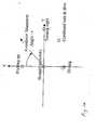
Fig. 1a is a diagram defining a coordinate system and a kinematic acceleration plane in which plane a desired avoidance manoeuvre angle is defined. -
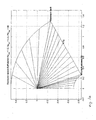
Fig. 1b is a graphical representation of a cascade of avoidance manoeuvre angles in the kinematic acceleration plane offig. 1a . -
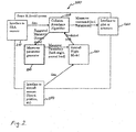
Fig. 2 is a block diagram of a collision avoidance system. -
Fig. 3 is a flowchart of a method useable for selecting an avoidance manoeuvre. -
Fig. 4 is a manoeuvre parameter generator with input and outputs -
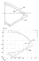
Fig. 5 shows a maximum and an adjusted kinematic acceleration vector envelope. -
Fig. 6 ,7 and 8 shows three cases of a kinematic acceleration diagram wherein an area is delimited between two kinematic acceleration envelopes - The purpose of the invention is to provide a method and a system to select an effective collision avoidance manoeuvre for an aircraft, said aircraft may be a vehicle with limited propulsive power and limited manoeuvrability (limited, e.g., as to magnitude of roll angles), which in turn makes avoidance manoeuvre selection more difficult. Thus, a more particular purpose of the present invention is to provide an effective collision avoidance manoeuvre generator for an UAV with strongly limited propulsive power and limited manoeuvrability.
- To maximize the performance of the sense & avoid system, the selected manoeuvres, the inventor has realised, should posses the following qualities:
- use maximum or near maximum of the safe physical manoeuvre capabilities.
- Cover the full range of possible manoeuvre directions, i.e., all "roll" directions.
- Have a gradual change in effectiveness between adjacent manoeuvre directions, to create good conditions for a manoeuvre optimizing routine to operate without problems.
- With a "low manoeuvrability aircraft" is for the purpose of the present application meant an aircraft having a limited roll angle, i.e., an aircraft not being able to roll 360 degrees, but instead being able to roll less than 180 degrees to the right and less than 180 degrees to the left. To this category of aircraft belong most UAVs but also most passenger aircraft.
- In the following, for the purposes of the present application, the phrases "collision avoidance manoeuvre", "avoidance manoeuvre", "evasive manoeuvre" and "escape manoeuvre" are used synonymously. So are their corresponding derivatives. The phrases "maximum kinematic acceleration vector envelope", "maximum kinematic acceleration envelope", and "maximum envelope" are used synonymously.
- The following symbols are used to denote certain parameters.
Symbol Parameter ε (epsilon) Avoidance Manoeuvre Angle (AMA) - π ≤ε≤π, i.e. -180°≤ε≤180° εt1 Avoidance Manoeuvre Angle at first transition point εt2 Avoidance Manoeuvre Angle at second transition point |ε| solute value of Avoidance Manoeuvre Angle Φ(fi) bank angle Φmax Maximum allowed bank angle θ (theta) pitch angle (angle between longitudinal axis of aircraft and said axis projection onto the ground plane.) a load g magnitude of the earths gravitational acceleration n z normal load (aircraft fixed coordinates) n z, min minimum normal load n z, max maximum normal load - Note that limitation terms (maximum, minimum) refer to the same for the particular craft in question. The invention will work for any craft, as long as the correct maximum and minimum parameters are used in the calculations.
- With reference now to
figure 1a and for the purpose of describing a desired avoidance manoeuvre a kinematic acceleration plane is defined, the shorter term "acceleration plane" may be used in the following. The acceleration plane allows us to graphically represent the manoeuvring capability of the (air)craft for the purpose of avoidance manoeuvring. In this representation we also implicitly ignore the capability to manoeuvre by reducing or increasing forward thrust, thus simplifying the task of creating manoeuvring algorithms. The acceleration plane is defined as follows, see alsofigure 1a : - The acceleration plane normal (Z-axle) is along the current velocity vector of the aircraft. (That is, into the paper of
fig. 1a .) - The acceleration plane Y-axle is parallel to the local earth plane, and such that the acceleration plane X-axle will point away from the ground when following the right hand rule. For an aircraft heading straight up or down, the Y-axle is chosen parallel to the body Y-axle to avoid an undefined state.
- In an acceleration plane diagram, the state of continuing the current trajectory is found in the origin of the acceleration plane. Pitching the aircraft upward is represented along the X-axle, using an acceleration unit for the magnitude (e.g. m/s2 or g:s). Making a coordinated turn to the right is represented along the Y-axle. Combinations of turning and pitching/descending can then be represented in the acceleration plane plot.
- In the acceleration plane we also define an Avoidance Manoeuvre Angle (AMA) denoted by the Greek letter ε (epsilon) as the angle around the Z-axle, counted clockwise from the X-axle, in which we would like to consider an avoidance manoeuvre. The Avoidance Manoeuvre Angle is provided from another unit of the sense & avoid system to the manoeuvre generator. Such a unit may suitably function as disclosed in the
document US 6, 510, 388 with or without the following modifications: - In the document is disclosed how to obtain suitable avoidance manoeuvre directions for two aircrafts, each provided with the system, and with a communications link between them. This may be done by minimizing the function
- A set comprising avoidance manoeuvre directions Di per participating aircraft is then calculated for which the resulting function f is minimal. Due to calculational constraints it may be required and sufficient to assume a finite number of variations of Di for each aircraft and chose the respective Di:s for which f is minimized. For the non-cooperative case only the own Di is calculated since all other objects are assumed to be on a straight trajectory.
- The system may easily be expanded for the non-cooperative case to use trajectories other than straight provided this information can be obtained from some sensor or other source of information.
- Considering an aircraft that is limited by a maximum bank angle and a maximum and a minimum normal load, there are three limit manoeuvres that can be performed. ( In this context a limit manoeuvre is a manoeuvre that takes the aircraft to one or more of its limits)
- A manoeuvre at maximum normal load, with a varied bank angle.
- A manoeuvre at maximum bank angle, with a varied normal load.
- A manoeuvre at minimum normal load, with a varied bank angle.
- The combination of these three limit manoeuvres allows for a complete revolution of Avoidance Manoeuvre Angles ε to be obtained by the below described procedure.
- It is assumed that the minimum normal load is greater 0 and that the maximum bank angle is less than 90 degrees.
-
Figure 1b shows a graphical representation of a cascade of Avoidance Manoeuvre Angles (AMAs) ε in the kinematic acceleration plane and possible for a manoeuvre to the right, 0 <= ε < 180 degrees. A corresponding figure can be drawn for left hand manoeuvres, 0 > ε > -180. For descriptive purposes however, only the right hand case will be studied. It is assumed that a desired Avoidance Manoeuvre Angle ε is already determined, for example as described above fromUS 6, 510, 388 - The transition points are given by:


- It is understood from the formulae that a transition point is expressed as an angle. The first transition point εt1 is the point (angle) corresponding to a case where maximum bank angle and maximum normal load under current pitch angle (and speed) are adopted. The εt1-angle may be determined as the arcus tangens two (atan2), wherein the two input arguments to the atan2 function are:
- argument 1: a term expressed as maximum normal load n z, max multiplied with the sine of maximum bank angle Φmax
- argument 2: a term expressed as the difference between maximum normal load a z, max multiplied with the cosine of maximum bank angle Φmax and the value of the earths gravity multiplied with the cosine of the current pitch angle θ
- The second transition point εt2 is the angle corresponding to a minimum normal load and a maximum bank angle. The εt2-angle may be determined as the arcus tangens two (atan2), wherein the two input arguments to the atan2 function are:
- argument 1: a term expressed as minimum normal load n z, min multiplied with the sine of maximum bank angle Φmax
- argument 2: a term expressed as the difference between the product of minimum normal load n z, min multiplied with the cosine of maximum bank angle Φmax, and the product of the value of the earths gravity multiplied with the cosine of the current pitch angle θ
- |ε| ≤ ε t1, manoeuvre using max normal load, vary bank angle.
- ε t1 < |ε| ≤ εt2 , manoeuvre using max bank angle, vary normal load
- ε t2 < |ε|, manoeuvre using minimum normal load, vary bank angle.
- For each avoidance manoeuvre angle ε there is implicitly a maximum kinematic acceleration a that can be obtained given the limiting maximum bank angle, minimum normal load and maximum normal load. The kinematic acceleration a corresponding to a particular avoidance manoeuvre angle ε may be determined by calculation where it is taken into account the features of the aircraft model in question, or by adequate simulation, or by a combination thereof. When the kinematic acceleration is determined for each, or a representative number of avoidance manoeuvre angles, a maximum kinetic acceleration envelope can be drawn up in the kinematic acceleration plane using avoidance manoeuvre angle and kinematic acceleration respectively as polar coordinates for points on said envelope. The gap between points can be interpolated.
- When maneuvering according to the maximum normal load, maximum bank angle or minimum normal load method outlined above the bank angle and normal load can be obtained in closed form without explicitly calculating the resulting kinematical acceleration. How to calculate these parameters follow below.
- In the case of maximum normal load:

- In this case bank angle Φ is determined as the difference between the avoidance manoeuvre angle ε and an expression taking into account the effect of the g-force. In particular, bank angle may be determined as the difference between the avoidance manoeuvre angle e and a term built from arcus sinus of the product formed by multiplying g with the cosine of the current pitch angle further multiplied with the sine of the avoidance manoeuvre angle ε, divided by normal load.
- Normal load n z is determined as maximum normal load for the aircraft model in question.
- It may also be advantageous to determine parameters such as maximum normal load, maximum bank angle etc, taking not only into account the situation for the aircraft model in question, but the situation for the particular individual aircraft in question and during the situation of the particular mission.
- In the case of maximum bank angle

- In the case of minimum normal load


- The definition of the two argument function arctan2, also known as "atan2" is the conventional one, well known in the art, which can be found in any comprehensive computer science textbook or programming manual. Other mentioned functions are also defined as they conventionally are.
-
Figure 2 shows a block diagram of a sense andavoidance system 200 according to the invention, which system comprises the following units: - a
S&A interface 210 for interfacing sense and avoidance sensors, such as e.g. radar, TV-camera(s), infrared camera(s) , transponder(s) and for providing sense and avoidance data to a collisionavoidance algorithm unit 220; - a collision
avoidance algorithm unit 220 for calculating, based on sense and avoidance data, a suggested manoeuvre, i.e., an avoidance manoeuvre angle ε; - a
manoeuvre parameter generator 230 for determining manoeuvre parameters, i.e., for determining a bank angle and a normal load, based on said avoidance manoeuvre angle ε; - an aircraft
flight model unit 240 for determining, based on the manoeuvre parameters and on aircraft sensor data from aircraft sensors (speed, position etc), a predicted path (cf "Tr" above) of the aircraft for further distribution to the collisionavoidance algorithm unit 220; - an aircraft
sensors interface unit 250 for interfacing aircraft sensors and to provide aircraft sensor data to the aircraftflight model unit 240; - an aircraft
actuator interface unit 260 for for receiving manoeuvre command parameters determined by the collisionavoidance algorithm unit 220, based on predicted path data sent from the aircraftflight model unit 240 to the collisionavoidance algorithm unit 220, and for interfacing aircraft (UAV) actuators. - An avoidance
manoeuvre parameter generator manoeuvre parameter generator manoeuvre parameter generator figure 4 . The method may be realised using computer software or hardware as is known in the art. - With reference to
figure 3 , a method according to the invention may comprise the following steps: - Receiving 310a desired avoidance manoeuvre angle ε representing an angle in an acceleration plane as defined above;
- Calculating 320 a first transition point εt1 as the absolute avoidance manoeuvre angle above which it would be most efficient for the aircraft to do a manoeuvre at maximum bank angle and use a certain normal load to attain the desired avoidance manoeuvre angle ε, to achieve an avoidance manoeuvre with as much curvature as possible, given the constraints of the aircraft in question, in order to quickly leave a trajectory having great risk of collision.
- Calculating 330 a second transition point εt2 as the absolute avoidance manoeuvre angle above which it would be most efficient for the aircraft to do a manoeuvre at minimum normal load and use a certain bank angle to attain the desired avoidance manoeuvre angle ε; to achieve an avoidance manoeuvre with as much curvature as possible, given the constraints of the aircraft in question, in order to quickly leave a trajectory having great risk of collision.
- Comparing 340 the absolute value of the desired avoidance manoeuvre angle ε with the values of the first transition point εt1 and the second transition point εt2
- Acting according to the following cases
- Case 1: If 350 the absolute value of desired avoidance manoeuvre angle ε is greater than zero but less than the value of transition point εt1 then the suggested parameters for avoidance manoeuvre is set as follows:
- the normal load is set to maximum normal load nz, max
- the bank angle Φ is set to a value according to the expression ( I ) above, which would create the desired avoidance manoeuvre angle when executed together with the suggested normal load
- Case 2: If 360 the absolute value of desired avoidance manoeuvre angle ε is greater than the value of the first transition point εt1 but less than the value of the second transition point εt2 then the suggested parameters for avoidance manoeuvre is set as follows:
- the normal load is set to a value according to expression ( II ) above, which would create the desired avoidance manoeuvre angle when executed together with the suggested bank angle Φ;
- the bank angle Φ is set to maximum allowed bank angle;
- Case 3: If 370 the absolute value of desired avoidance manoeuvre angle ε is greater than the value of the second transition point εt2 then the suggested parameters for avoidance manoeuvre is set as follows
- the normal load is set to minimum normal load nz, min ;
- the bank angle Φ is set to a value according to the expression (I ) above, which would create the desired avoidance manoeuvre angle ε when executed together with the suggested normal load.
- Sometimes it may prove advantageous not to use the full maneuvering capabilities of the aircraft in question. One known reason for this is that an optimizer or an optimizing function of a collision avoidance maneuver selector may need a smoother function to work with than that provided by the aforementioned method, otherwise it may happen that a suboptimal Avoidance Manoeuvre Angle eventually may be chosen. There may also be a need to optimize the maneuver envelope to provide a bias toward a desired type of avoidance maneuvers.
- However, once the aforementioned method has been used to determine a maximum[kinematic acceleration envelope in the kinematic acceleration plane, this envelope can then be adjusted to any general envelope shape that fulfills the requirements that; there shall only be one magnitude of the kinematic acceleration a for a given Avoidance Manoeuvre Angle ε and such an adjusted envelope described shall lie inside the maximum envelope formed by the aforementioned method. An adjusted envelope may be an analytical function or a tabulated function. The selection of the envelope may be manual or it may be optimized by automated means such as for example parameter variation using a steepest gradient method.
-
Figure 5 shows one suchadjusted envelope 520 which is formed by defining an ellipse that lies within themaximum envelope 510. Again only the right hand side of the acceleration plane is illustrated. This exemplary envelope is thus described by the ellipse formula:

- Where A and B are the magnitudes of the half axis and h and k are offsets of the ellipse foci. For the
figure 5 the exemplary values for illustration is selected as: - A = 0.5g
- B = 1.1g
- h = -0.1g
- k = 0.0g
- After such an envelope has been defined, the maneuver parameters as per above is selected by determining the magnitude of the kinematic acceleration a to the defined envelope for a given Avoidance Manoeuvre Angle ε
- In the exemplary case of the ellipse envelope the magnitude is then described by:

- After the magnitude of the kinematic acceleration a has been determined the maneuvering parameters can regardless of the shape of the envelope be determined by the steps:


- An adjusted kinematic acceleration envelope may be created in the kinematic acceleration plane by forming a new envelope, the new envelope at each point laying closer to or at the same distance from the origin (0,0) as the points of the maximum kinematic acceleration envelope and such that there is only one value of the kinematic acceleration a for a given avoidance manoeuvre angle ε. In
figures 6 ,7 and 8 are shown examples of areas within the kinematic acceleration plane where it is suitable according to the invention to locate such an adjusted kinematic acceleration envelope. -
Figure 6 shows a kinematic acceleration diagram wherein anarea 630 between the maximumkinematic acceleration envelope 610 and a circular adjustedkinematic acceleration envelope 620 is delimited. Good avoidance manoeuvre determining methods according to the present invention is obtained by locating the kinematic acceleration envelope for selecting kinematic acceleration, and the therewith associated normal load, and bank angle, within the area limited by these two boundary curves. -
Figure 7 shows a kinematic acceleration diagram wherein anarea 730 between the maximumkinematic acceleration envelope 710 and an elliptic adjustedkinematic acceleration envelope 720 is delimited. High performance avoidance manoeuvre determining methods according to the present invention is obtained by locating the kinematic acceleration envelope for selecting kinematic acceleration, and the therewith associated normal load, and bank angle, within the area limited by these two boundary curves. -
Figure 8 shows a kinematic acceleration diagram wherein anarea 830 is delimited between the maximumkinematic acceleration envelope 810 and a similar shaped adjustedkinematic acceleration envelope 820 constituded of a 5 to 10 percent reduced version of the maximumkinematic acceleration envelope 810. High performance avoidance manoeuvre determining methods according to the present invention can also be obtained by locating the kinematic acceleration envelope for selecting kinematic acceleration, and the therewith associated normal load, and bank angle, within the area limited by these two boundary curves.

where Ci is the completion point (also closest point of approach) of the avoidance manoeuvre trajectory Tri for the vehicle "i" with regard to the (avoidance) manoeuvre trajectory Trj for the vehicle j. The function f is consequently the sum of the inverted distance between the completion points Ci, Cj of the avoidance manoeuvre trajectories Tri, Trj of all vehicles. In the case of a non-cooperative operation where manoeuvre selection of other aircraft are not known, Tr of other aircraft is selected as a straight line in space over time. The vehicle may also be a fixed or slow moving object such as a stationary ballon, paraglider, moving ballon, parachuter, helicopter or the like. For a stationary object Tr is a point in space over time.
Claims (11)
- A method for automatically determining an avoidance manoeuvre in an automatic collision avoidance system of an aircraft, the method comprising the following steps:- determining a maximum kinematic acceleration envelope by for a number of avoidance manoeuvre angles determining a corresponding number of corresponding kinematic accelerations in a kinematic acceleration plane, hereby defining a number of points, and interpolating the gaps between the points, thus creating the maximum kinematic acceleration envelope (510, 610, 810);- forming an adjusted kinematic acceleration envelope (520, 620, 820) in said plane by forming a new envelope, the new envelope at each point laying closer to or at the same distance from the origin (0,0) as the points of the maximum kinematic acceleration envelope and such that for a given avoidance manoeuvre angle (ε), there is one value of the kinematic acceleration (a);- Receiving a desired avoidance manoeuvre angle (ε);- Determining the magnitude of the kinematic acceleration (a) corresponding to the adjusted kinematic acceleration envelope (520, 620, 820) for the avoidance manoeuvre angle (ε), by reading the adjusted envelope curve;- Determining the normal load (nz), and the bank angle (Φ) based on the kinematic acceleration (a), and the avoidance manoeuvre angle (ε);
- The method of claim 1 wherein the maximum kinematic acceleration envelope is approximated by an analytical expression.
- The method of claim 1 or 2 wherein the adjusted kinematic acceleration envelope is approximated by an analytical expression and wherein the kinematic acceleration (a) is calculated by using said analytical expression.
- The method of claim 1, 2 or 3 wherein the normal load (n z )is determined as a square root expression.
- The method of claim 1, 2 or 3 wherein the bank angle is determined as arcus sinus function of an expression.
- The method of claim 4 wherein the normal load (nz ) is determined as

- The method of claim 5 wherein the bank angle (Φ) is determined as

- The method of claim 1 for an aircraft capable of automatically performing a collision avoidance manoeuvre for selecting the two collision avoidance manoeuvre parameters normal load, and bank angle, the method comprising the following steps:- Receiving (310) a desired avoidance manoeuvre angle ε as an angle in a kinematic acceleration plane- Calculating (320) a first transition point (εt1) as the absolute avoidance manoeuvre angle above which it would be most efficient for the aircraft to do a manoeuvre at maximum bank angle and use a certain normal load to attain the desired avoidance manoeuvre angle (ε), to achieve an avoidance manoeuvre with as much curvature as possible, given the constraints of the aircraft in question, in order to quickly leave a trajectory having great risk of collision.- Calculating (330) a second transition point (εt2) as the absolute avoidance manoeuvre angle above which it would be more efficient for the aircraft to do a manoeuvre at minimum normal load and use a certain bank angle to attain the desired avoidance manoeuvre angle (ε), to achieve an avoidance manoeuvre with as much curvature as possible, given the constraints of the aircraft in question, in order to quickly leave a trajectory having great risk of collision.;- Comparing (340) the absolute value of the desired avoidance manoeuvre angle ε with the values of the first transition point εt1 and the second transition point (εt2)- Acting according to one of the following casesCase 1: If (350) the absolute value of desired avoidance manoeuvre angle ε is greater than zero but less than the value of transition point (εt1) then the suggested parameters for avoidance manoeuvre is set as follows:- the normal load is set to maximum normal load (nz, max);- the bank angle (Φ) is set to a value which would create the desired avoidance manoeuvre angle when executed together with the suggested normal load;Case 2: If (360) the absolute value of desired avoidance manoeuvre angle ε is greater than the value of the first transition point εt1 but less than the value of the second transition point εt2 then the suggested parameters for avoidance manoeuvre is set as follows:- the normal load is set to a value, which would create the desired avoidance manoeuvre angle when executed together with the suggested bank angle (Φ);- the bank angle (Φ) is set to maximum allowed bank angle (Φmax)Case 3: If (370) the absolute value of desired avoidance manoeuvre angle (ε) is greater than the value of the second transition point (εt2) then the suggested parameters for collision avoidance manoeuvre is set as follows- the normal load is set to minimum normal load (nz, min)- the bank angle (Φ) is set to a value, which would create the desired avoidance manoeuvre angle when executed together with the suggested normal load.
- A sense and avoidance system for an unmanned aerial vehicle comprising an avoidance manoeuvre parameter generator realising the steps of claim1.
- A sense and avoidance system for a manned aerial vehicle comprising an avoidance maneouvre parameter generator realising the steps of claim 1.
- An avoidance manoeuvre parameter generator realising the steps of claim1.
Priority Applications (5)
| Application Number | Priority Date | Filing Date | Title |
|---|---|---|---|
| ES08168257T ES2378787T3 (en) | 2008-11-04 | 2008-11-04 | Generator of avoidance maneuvers for an aircraft |
| AT08168257T ATE545924T1 (en) | 2008-11-04 | 2008-11-04 | AVOIDANCE MANEUVER GENERATOR FOR AN AIRCRAFT |
| EP08168257A EP2182419B1 (en) | 2008-11-04 | 2008-11-04 | Avoidance manoeuvre generator for an aircraft |
| BRPI0904274-1A BRPI0904274B1 (en) | 2008-11-04 | 2009-11-04 | avoidance shunt generator for an aircraft |
| US12/612,088 US8355861B2 (en) | 2008-11-04 | 2009-11-04 | Avoidance manoeuvre generator for an aircraft |
Applications Claiming Priority (1)
| Application Number | Priority Date | Filing Date | Title |
|---|---|---|---|
| EP08168257A EP2182419B1 (en) | 2008-11-04 | 2008-11-04 | Avoidance manoeuvre generator for an aircraft |
Publications (2)
| Publication Number | Publication Date |
|---|---|
| EP2182419A1 true EP2182419A1 (en) | 2010-05-05 |
| EP2182419B1 EP2182419B1 (en) | 2012-02-15 |
Family
ID=40428259
Family Applications (1)
| Application Number | Title | Priority Date | Filing Date |
|---|---|---|---|
| EP08168257A Active EP2182419B1 (en) | 2008-11-04 | 2008-11-04 | Avoidance manoeuvre generator for an aircraft |
Country Status (5)
| Country | Link |
|---|---|
| US (1) | US8355861B2 (en) |
| EP (1) | EP2182419B1 (en) |
| AT (1) | ATE545924T1 (en) |
| BR (1) | BRPI0904274B1 (en) |
| ES (1) | ES2378787T3 (en) |
Cited By (8)
| Publication number | Priority date | Publication date | Assignee | Title |
|---|---|---|---|---|
| WO2015175379A1 (en) * | 2014-05-10 | 2015-11-19 | Aurora Flight Sciences Corporation | Autonomous aerial vehicle collision avoidance system and method |
| CN105843255A (en) * | 2016-05-12 | 2016-08-10 | 深圳市艾博航空模型技术有限公司 | Unmanned aerial vehicle cluster automatic flight crashproof apparatus and crashproof method |
| WO2017125084A1 (en) * | 2016-01-20 | 2017-07-27 | 厦门施米德智能科技有限公司 | Unmanned aerial vehicle express system based on smart window |
| US9880006B2 (en) | 2014-03-15 | 2018-01-30 | Aurora Flight Sciences Corporation | Autonomous vehicle navigation system and method |
| CN108073176A (en) * | 2018-02-10 | 2018-05-25 | 西安交通大学 | A kind of modified D*Lite vehicle dynamic path planing methods |
| US10520944B2 (en) | 2017-01-06 | 2019-12-31 | Aurora Flight Sciences Corporation | Collision avoidance system and method for unmanned aircraft |
| US11037453B2 (en) | 2018-10-12 | 2021-06-15 | Aurora Flight Sciences Corporation | Adaptive sense and avoid system |
| US11119212B2 (en) | 2018-08-10 | 2021-09-14 | Aurora Flight Sciences Corporation | System and method to reduce DVE effect on lidar return |
Families Citing this family (24)
| Publication number | Priority date | Publication date | Assignee | Title |
|---|---|---|---|---|
| FR2932919B1 (en) * | 2008-06-24 | 2010-08-20 | Eurocopter France | ADAPTATION OF SELECTIVE FIELD ALERTS, BASED ON THE INSTANTANEOUS MANOEUVRABILITY OF A GIRAVION |
| CN103995539B (en) * | 2014-05-15 | 2016-04-20 | 北京航空航天大学 | A kind of unmanned plane autonomous formation evaluation index and MPC formation control method |
| US9812021B2 (en) * | 2014-06-25 | 2017-11-07 | Amazon Technologies, Inc. | Object avoidance for automated aerial vehicles |
| US9764736B2 (en) * | 2015-08-14 | 2017-09-19 | Toyota Motor Engineering & Manufacturing North America, Inc. | Autonomous vehicle operation relative to unexpected dynamic objects |
| CN107209854A (en) | 2015-09-15 | 2017-09-26 | 深圳市大疆创新科技有限公司 | Systems and methods for supporting smooth object following |
| US9701307B1 (en) | 2016-04-11 | 2017-07-11 | David E. Newman | Systems and methods for hazard mitigation |
| US10543852B2 (en) * | 2016-08-20 | 2020-01-28 | Toyota Motor Engineering & Manufacturing North America, Inc. | Environmental driver comfort feedback for autonomous vehicle |
| US10878708B2 (en) * | 2017-03-03 | 2020-12-29 | Farrokh Mohamadi | Drone terrain surveillance with camera and radar sensor fusion for collision avoidance |
| US10228692B2 (en) | 2017-03-27 | 2019-03-12 | Gulfstream Aerospace Corporation | Aircraft flight envelope protection and recovery autopilot |
| US10719705B2 (en) | 2018-01-03 | 2020-07-21 | Qualcomm Incorporated | Adjustable object avoidance proximity threshold based on predictability of the environment |
| US10717435B2 (en) | 2018-01-03 | 2020-07-21 | Qualcomm Incorporated | Adjustable object avoidance proximity threshold based on classification of detected objects |
| US10720070B2 (en) | 2018-01-03 | 2020-07-21 | Qualcomm Incorporated | Adjustable object avoidance proximity threshold of a robotic vehicle based on presence of detected payload(s) |
| US10636314B2 (en) | 2018-01-03 | 2020-04-28 | Qualcomm Incorporated | Adjusting flight parameters of an aerial robotic vehicle based on presence of propeller guard(s) |
| US10803759B2 (en) | 2018-01-03 | 2020-10-13 | Qualcomm Incorporated | Adjustable object avoidance proximity threshold based on presence of propeller guard(s) |
| CN112673409B (en) * | 2018-08-27 | 2023-08-29 | 湾流航空航天公司 | Predicted aircraft flight envelope protection system |
| US10816635B1 (en) | 2018-12-20 | 2020-10-27 | Autonomous Roadway Intelligence, Llc | Autonomous vehicle localization system |
| US10820349B2 (en) | 2018-12-20 | 2020-10-27 | Autonomous Roadway Intelligence, Llc | Wireless message collision avoidance with high throughput |
| US10939471B2 (en) | 2019-06-13 | 2021-03-02 | David E. Newman | Managed transmission of wireless DAT messages |
| US10820182B1 (en) | 2019-06-13 | 2020-10-27 | David E. Newman | Wireless protocols for emergency message transmission |
| US10713950B1 (en) | 2019-06-13 | 2020-07-14 | Autonomous Roadway Intelligence, Llc | Rapid wireless communication for vehicle collision mitigation |
| EP3859474B1 (en) * | 2020-01-31 | 2024-04-17 | Ningbo Geely Automobile Research & Development Co., Ltd. | Unmanned aerial vehicle configured to be operated relative to a land vehicle |
| US11206169B1 (en) | 2020-11-13 | 2021-12-21 | Ultralogic 5G, Llc | Asymmetric modulation for high-reliability 5G communications |
| US20220183068A1 (en) | 2020-12-04 | 2022-06-09 | David E. Newman | Rapid Uplink Access by Parallel Signaling on a 5G Random-Access Channel |
| CN115793679B (en) * | 2022-09-29 | 2026-04-17 | 北京空间飞行器总体设计部 | An Autonomous Decision-Making Method for Multi-Payment Space Platform Systems Considering Plume Avoidance |
Citations (5)
| Publication number | Priority date | Publication date | Assignee | Title |
|---|---|---|---|---|
| EP0609162A2 (en) * | 1993-01-28 | 1994-08-03 | State Of Israel Ministry Of Defence Rafael Armament Development Authority | Airborne obstacle collision avoidance apparatus |
| US6168117B1 (en) * | 1996-07-05 | 2001-01-02 | Fuji Jukogyo Kabushiki Kaisha | Flight control system for airplane |
| US6510388B1 (en) | 1999-12-22 | 2003-01-21 | Saab Ab | System and method for avoidance of collision between vehicles |
| FR2876483A1 (en) * | 2004-10-08 | 2006-04-14 | Airbus France Sas | METHOD AND SYSTEM FOR AVOIDING AN AIRCRAFT |
| US20070210953A1 (en) | 2006-03-13 | 2007-09-13 | Abraham Michael R | Aircraft collision sense and avoidance system and method |
-
2008
- 2008-11-04 EP EP08168257A patent/EP2182419B1/en active Active
- 2008-11-04 AT AT08168257T patent/ATE545924T1/en active
- 2008-11-04 ES ES08168257T patent/ES2378787T3/en active Active
-
2009
- 2009-11-04 US US12/612,088 patent/US8355861B2/en active Active
- 2009-11-04 BR BRPI0904274-1A patent/BRPI0904274B1/en active IP Right Grant
Patent Citations (5)
| Publication number | Priority date | Publication date | Assignee | Title |
|---|---|---|---|---|
| EP0609162A2 (en) * | 1993-01-28 | 1994-08-03 | State Of Israel Ministry Of Defence Rafael Armament Development Authority | Airborne obstacle collision avoidance apparatus |
| US6168117B1 (en) * | 1996-07-05 | 2001-01-02 | Fuji Jukogyo Kabushiki Kaisha | Flight control system for airplane |
| US6510388B1 (en) | 1999-12-22 | 2003-01-21 | Saab Ab | System and method for avoidance of collision between vehicles |
| FR2876483A1 (en) * | 2004-10-08 | 2006-04-14 | Airbus France Sas | METHOD AND SYSTEM FOR AVOIDING AN AIRCRAFT |
| US20070210953A1 (en) | 2006-03-13 | 2007-09-13 | Abraham Michael R | Aircraft collision sense and avoidance system and method |
Cited By (15)
| Publication number | Priority date | Publication date | Assignee | Title |
|---|---|---|---|---|
| US9880006B2 (en) | 2014-03-15 | 2018-01-30 | Aurora Flight Sciences Corporation | Autonomous vehicle navigation system and method |
| US11029157B2 (en) | 2014-03-15 | 2021-06-08 | Aurora Flight Sciences Corporation | Autonomous vehicle navigation system and method |
| US10062294B2 (en) | 2014-05-10 | 2018-08-28 | Aurora Flight Sciences Corporation | Dynamic collision-avoidance system and method |
| US9875661B2 (en) | 2014-05-10 | 2018-01-23 | Aurora Flight Sciences Corporation | Dynamic collision-avoidance system and method |
| WO2015175379A1 (en) * | 2014-05-10 | 2015-11-19 | Aurora Flight Sciences Corporation | Autonomous aerial vehicle collision avoidance system and method |
| US10276051B2 (en) | 2014-05-10 | 2019-04-30 | Aurora Flight Sciences Corporation | Dynamic collision-avoidance system and method |
| WO2017125084A1 (en) * | 2016-01-20 | 2017-07-27 | 厦门施米德智能科技有限公司 | Unmanned aerial vehicle express system based on smart window |
| CN105843255B (en) * | 2016-05-12 | 2019-03-05 | 深圳市艾博航空模型技术有限公司 | The anticollision device, collision-prevention device and avoiding collision of unmanned plane cluster autonomous flight |
| CN105843255A (en) * | 2016-05-12 | 2016-08-10 | 深圳市艾博航空模型技术有限公司 | Unmanned aerial vehicle cluster automatic flight crashproof apparatus and crashproof method |
| US10520944B2 (en) | 2017-01-06 | 2019-12-31 | Aurora Flight Sciences Corporation | Collision avoidance system and method for unmanned aircraft |
| US11092964B2 (en) | 2017-01-06 | 2021-08-17 | Aurora Flight Sciences Corporation | Collision-avoidance system and method for unmanned aircraft |
| CN108073176A (en) * | 2018-02-10 | 2018-05-25 | 西安交通大学 | A kind of modified D*Lite vehicle dynamic path planing methods |
| US11119212B2 (en) | 2018-08-10 | 2021-09-14 | Aurora Flight Sciences Corporation | System and method to reduce DVE effect on lidar return |
| US11037453B2 (en) | 2018-10-12 | 2021-06-15 | Aurora Flight Sciences Corporation | Adaptive sense and avoid system |
| US12002373B2 (en) | 2018-10-12 | 2024-06-04 | Aurora Flight Sciences Corporation, a subsidiary of The Boeing Company | Adaptive sense and avoid system |
Also Published As
| Publication number | Publication date |
|---|---|
| EP2182419B1 (en) | 2012-02-15 |
| ATE545924T1 (en) | 2012-03-15 |
| BRPI0904274B1 (en) | 2019-11-12 |
| US20100179760A1 (en) | 2010-07-15 |
| US8355861B2 (en) | 2013-01-15 |
| ES2378787T3 (en) | 2012-04-17 |
| BRPI0904274A2 (en) | 2011-02-01 |
Similar Documents
| Publication | Publication Date | Title |
|---|---|---|
| EP2182419B1 (en) | Avoidance manoeuvre generator for an aircraft | |
| US11900824B2 (en) | Predictive aircraft flight envelope protection system | |
| US8150621B1 (en) | Command and control of autonomous surface vehicle | |
| Karimi et al. | Optimal maneuver-based motion planning over terrain and threats using a dynamic hybrid PSO algorithm | |
| KR20200143292A (en) | Three dimensional aircraft autonomous navigation under constraints | |
| CN106842926A (en) | A kind of aerial vehicle trajectory optimization method based on positive real B-spline | |
| Wiig et al. | A 3D reactive collision avoidance algorithm for nonholonomic vehicles | |
| CN109901387A (en) | A kind of automatic near-earth anti-collision system Self-adaptive flight trajectory predictions method of aircraft | |
| US11273928B2 (en) | Time available before aircraft auto-recovery begins | |
| Manathara et al. | Reactive collision avoidance of multiple realistic UAVs | |
| CN111290426A (en) | Prediction control method for automatically avoiding escape path of aircraft | |
| Lee et al. | Guidance and control for autonomous emergency landing of the rotorcraft using the incremental backstepping controller in 3-dimensional terrain environments | |
| Kim et al. | Vision‐assisted deep stall landing for a fixed‐wing UAV | |
| Wang et al. | Safer uav piloting: A robust sense-and-avoid solution for remotely piloted quadrotor uavs in complex environments | |
| Di Donato | Toward autonomous aircraft emergency landing planning | |
| Rahim et al. | Aircraft terrain following flights based on fuzzy logic | |
| Di Donato et al. | Three-dimensional dubins path generation and following for a uas glider | |
| Cheng et al. | Nonlinear control for UAV formation flying | |
| Johansen et al. | Guidance, Navigation, and Control of Fixed-Wing Unmanned Aerial Vehicles | |
| Fan | Optimal path planning and control of quadrotor unmanned aerial vehicle for area coverage | |
| Atkins | Dynamic waypoint generation given reduced flight performance | |
| Wellman et al. | Sampled-data flocking with application to unmanned rotorcraft | |
| Jiang et al. | Collision avoidance algorithm between quadrotors using optimal control and pseudospectral method | |
| Singletary et al. | Safety Guardrails in the Sky: Realizing Control Barrier Functions on the VISTA F-16 Jet | |
| Morillo et al. | On-board Artificial Intelligence for Failure Detection and Safe Trajectory Generation |
Legal Events
| Date | Code | Title | Description |
|---|---|---|---|
| PUAI | Public reference made under article 153(3) epc to a published international application that has entered the european phase |
Free format text: ORIGINAL CODE: 0009012 |
|
| AK | Designated contracting states |
Kind code of ref document: A1 Designated state(s): AT BE BG CH CY CZ DE DK EE ES FI FR GB GR HR HU IE IS IT LI LT LU LV MC MT NL NO PL PT RO SE SI SK TR |
|
| AX | Request for extension of the european patent |
Extension state: AL BA MK RS |
|
| 17P | Request for examination filed |
Effective date: 20101101 |
|
| 17Q | First examination report despatched |
Effective date: 20101130 |
|
| AKX | Designation fees paid |
Designated state(s): AT BE BG CH CY CZ DE DK EE ES FI FR GB GR HR HU IE IS IT LI LT LU LV MC MT NL NO PL PT RO SE SI SK TR |
|
| REG | Reference to a national code |
Ref country code: DE Ref legal event code: R079 Ref document number: 602008013425 Country of ref document: DE Free format text: PREVIOUS MAIN CLASS: G05D0001100000 Ipc: G08G0005000000 |
|
| GRAP | Despatch of communication of intention to grant a patent |
Free format text: ORIGINAL CODE: EPIDOSNIGR1 |
|
| RIC1 | Information provided on ipc code assigned before grant |
Ipc: G05D 1/10 20060101ALI20110914BHEP Ipc: G08G 5/00 20060101AFI20110914BHEP Ipc: G08G 5/04 20060101ALI20110914BHEP |
|
| GRAS | Grant fee paid |
Free format text: ORIGINAL CODE: EPIDOSNIGR3 |
|
| GRAA | (expected) grant |
Free format text: ORIGINAL CODE: 0009210 |
|
| AK | Designated contracting states |
Kind code of ref document: B1 Designated state(s): AT BE BG CH CY CZ DE DK EE ES FI FR GB GR HR HU IE IS IT LI LT LU LV MC MT NL NO PL PT RO SE SI SK TR |
|
| REG | Reference to a national code |
Ref country code: GB Ref legal event code: FG4D Ref country code: CH Ref legal event code: EP |
|
| REG | Reference to a national code |
Ref country code: IE Ref legal event code: FG4D |
|
| REG | Reference to a national code |
Ref country code: AT Ref legal event code: REF Ref document number: 545924 Country of ref document: AT Kind code of ref document: T Effective date: 20120315 |
|
| REG | Reference to a national code |
Ref country code: ES Ref legal event code: FG2A Ref document number: 2378787 Country of ref document: ES Kind code of ref document: T3 Effective date: 20120417 |
|
| REG | Reference to a national code |
Ref country code: DE Ref legal event code: R096 Ref document number: 602008013425 Country of ref document: DE Effective date: 20120419 |
|
| REG | Reference to a national code |
Ref country code: NL Ref legal event code: VDEP Effective date: 20120215 |
|
| LTIE | Lt: invalidation of european patent or patent extension |
Effective date: 20120215 |
|
| PG25 | Lapsed in a contracting state [announced via postgrant information from national office to epo] |
Ref country code: NL Free format text: LAPSE BECAUSE OF FAILURE TO SUBMIT A TRANSLATION OF THE DESCRIPTION OR TO PAY THE FEE WITHIN THE PRESCRIBED TIME-LIMIT Effective date: 20120215 Ref country code: LT Free format text: LAPSE BECAUSE OF FAILURE TO SUBMIT A TRANSLATION OF THE DESCRIPTION OR TO PAY THE FEE WITHIN THE PRESCRIBED TIME-LIMIT Effective date: 20120215 Ref country code: IS Free format text: LAPSE BECAUSE OF FAILURE TO SUBMIT A TRANSLATION OF THE DESCRIPTION OR TO PAY THE FEE WITHIN THE PRESCRIBED TIME-LIMIT Effective date: 20120615 Ref country code: HR Free format text: LAPSE BECAUSE OF FAILURE TO SUBMIT A TRANSLATION OF THE DESCRIPTION OR TO PAY THE FEE WITHIN THE PRESCRIBED TIME-LIMIT Effective date: 20120215 Ref country code: NO Free format text: LAPSE BECAUSE OF FAILURE TO SUBMIT A TRANSLATION OF THE DESCRIPTION OR TO PAY THE FEE WITHIN THE PRESCRIBED TIME-LIMIT Effective date: 20120515 |
|
| PG25 | Lapsed in a contracting state [announced via postgrant information from national office to epo] |
Ref country code: FI Free format text: LAPSE BECAUSE OF FAILURE TO SUBMIT A TRANSLATION OF THE DESCRIPTION OR TO PAY THE FEE WITHIN THE PRESCRIBED TIME-LIMIT Effective date: 20120215 Ref country code: LV Free format text: LAPSE BECAUSE OF FAILURE TO SUBMIT A TRANSLATION OF THE DESCRIPTION OR TO PAY THE FEE WITHIN THE PRESCRIBED TIME-LIMIT Effective date: 20120215 Ref country code: PL Free format text: LAPSE BECAUSE OF FAILURE TO SUBMIT A TRANSLATION OF THE DESCRIPTION OR TO PAY THE FEE WITHIN THE PRESCRIBED TIME-LIMIT Effective date: 20120215 Ref country code: PT Free format text: LAPSE BECAUSE OF FAILURE TO SUBMIT A TRANSLATION OF THE DESCRIPTION OR TO PAY THE FEE WITHIN THE PRESCRIBED TIME-LIMIT Effective date: 20120615 Ref country code: GR Free format text: LAPSE BECAUSE OF FAILURE TO SUBMIT A TRANSLATION OF THE DESCRIPTION OR TO PAY THE FEE WITHIN THE PRESCRIBED TIME-LIMIT Effective date: 20120516 Ref country code: BE Free format text: LAPSE BECAUSE OF FAILURE TO SUBMIT A TRANSLATION OF THE DESCRIPTION OR TO PAY THE FEE WITHIN THE PRESCRIBED TIME-LIMIT Effective date: 20120215 |
|
| REG | Reference to a national code |
Ref country code: AT Ref legal event code: MK05 Ref document number: 545924 Country of ref document: AT Kind code of ref document: T Effective date: 20120215 |
|
| PG25 | Lapsed in a contracting state [announced via postgrant information from national office to epo] |
Ref country code: CY Free format text: LAPSE BECAUSE OF FAILURE TO SUBMIT A TRANSLATION OF THE DESCRIPTION OR TO PAY THE FEE WITHIN THE PRESCRIBED TIME-LIMIT Effective date: 20120215 |
|
| PG25 | Lapsed in a contracting state [announced via postgrant information from national office to epo] |
Ref country code: DK Free format text: LAPSE BECAUSE OF FAILURE TO SUBMIT A TRANSLATION OF THE DESCRIPTION OR TO PAY THE FEE WITHIN THE PRESCRIBED TIME-LIMIT Effective date: 20120215 Ref country code: SE Free format text: LAPSE BECAUSE OF FAILURE TO SUBMIT A TRANSLATION OF THE DESCRIPTION OR TO PAY THE FEE WITHIN THE PRESCRIBED TIME-LIMIT Effective date: 20120215 Ref country code: RO Free format text: LAPSE BECAUSE OF FAILURE TO SUBMIT A TRANSLATION OF THE DESCRIPTION OR TO PAY THE FEE WITHIN THE PRESCRIBED TIME-LIMIT Effective date: 20120215 Ref country code: SI Free format text: LAPSE BECAUSE OF FAILURE TO SUBMIT A TRANSLATION OF THE DESCRIPTION OR TO PAY THE FEE WITHIN THE PRESCRIBED TIME-LIMIT Effective date: 20120215 Ref country code: CZ Free format text: LAPSE BECAUSE OF FAILURE TO SUBMIT A TRANSLATION OF THE DESCRIPTION OR TO PAY THE FEE WITHIN THE PRESCRIBED TIME-LIMIT Effective date: 20120215 Ref country code: EE Free format text: LAPSE BECAUSE OF FAILURE TO SUBMIT A TRANSLATION OF THE DESCRIPTION OR TO PAY THE FEE WITHIN THE PRESCRIBED TIME-LIMIT Effective date: 20120215 |
|
| PG25 | Lapsed in a contracting state [announced via postgrant information from national office to epo] |
Ref country code: SK Free format text: LAPSE BECAUSE OF FAILURE TO SUBMIT A TRANSLATION OF THE DESCRIPTION OR TO PAY THE FEE WITHIN THE PRESCRIBED TIME-LIMIT Effective date: 20120215 |
|
| PLBE | No opposition filed within time limit |
Free format text: ORIGINAL CODE: 0009261 |
|
| STAA | Information on the status of an ep patent application or granted ep patent |
Free format text: STATUS: NO OPPOSITION FILED WITHIN TIME LIMIT |
|
| 26N | No opposition filed |
Effective date: 20121116 |
|
| PG25 | Lapsed in a contracting state [announced via postgrant information from national office to epo] |
Ref country code: AT Free format text: LAPSE BECAUSE OF FAILURE TO SUBMIT A TRANSLATION OF THE DESCRIPTION OR TO PAY THE FEE WITHIN THE PRESCRIBED TIME-LIMIT Effective date: 20120215 |
|
| REG | Reference to a national code |
Ref country code: DE Ref legal event code: R097 Ref document number: 602008013425 Country of ref document: DE Effective date: 20121116 |
|
| REG | Reference to a national code |
Ref country code: CH Ref legal event code: PL |
|
| PG25 | Lapsed in a contracting state [announced via postgrant information from national office to epo] |
Ref country code: LI Free format text: LAPSE BECAUSE OF NON-PAYMENT OF DUE FEES Effective date: 20121130 Ref country code: BG Free format text: LAPSE BECAUSE OF FAILURE TO SUBMIT A TRANSLATION OF THE DESCRIPTION OR TO PAY THE FEE WITHIN THE PRESCRIBED TIME-LIMIT Effective date: 20120515 Ref country code: CH Free format text: LAPSE BECAUSE OF NON-PAYMENT OF DUE FEES Effective date: 20121130 |
|
| REG | Reference to a national code |
Ref country code: IE Ref legal event code: MM4A |
|
| PG25 | Lapsed in a contracting state [announced via postgrant information from national office to epo] |
Ref country code: IE Free format text: LAPSE BECAUSE OF NON-PAYMENT OF DUE FEES Effective date: 20121104 |
|
| PG25 | Lapsed in a contracting state [announced via postgrant information from national office to epo] |
Ref country code: MT Free format text: LAPSE BECAUSE OF FAILURE TO SUBMIT A TRANSLATION OF THE DESCRIPTION OR TO PAY THE FEE WITHIN THE PRESCRIBED TIME-LIMIT Effective date: 20120215 |
|
| PG25 | Lapsed in a contracting state [announced via postgrant information from national office to epo] |
Ref country code: TR Free format text: LAPSE BECAUSE OF FAILURE TO SUBMIT A TRANSLATION OF THE DESCRIPTION OR TO PAY THE FEE WITHIN THE PRESCRIBED TIME-LIMIT Effective date: 20120215 Ref country code: MC Free format text: LAPSE BECAUSE OF NON-PAYMENT OF DUE FEES Effective date: 20121130 |
|
| PG25 | Lapsed in a contracting state [announced via postgrant information from national office to epo] |
Ref country code: LU Free format text: LAPSE BECAUSE OF NON-PAYMENT OF DUE FEES Effective date: 20121104 |
|
| PG25 | Lapsed in a contracting state [announced via postgrant information from national office to epo] |
Ref country code: HU Free format text: LAPSE BECAUSE OF FAILURE TO SUBMIT A TRANSLATION OF THE DESCRIPTION OR TO PAY THE FEE WITHIN THE PRESCRIBED TIME-LIMIT Effective date: 20081104 |
|
| REG | Reference to a national code |
Ref country code: FR Ref legal event code: PLFP Year of fee payment: 8 |
|
| REG | Reference to a national code |
Ref country code: FR Ref legal event code: PLFP Year of fee payment: 9 |
|
| REG | Reference to a national code |
Ref country code: FR Ref legal event code: PLFP Year of fee payment: 10 |
|
| PGFP | Annual fee paid to national office [announced via postgrant information from national office to epo] |
Ref country code: ES Payment date: 20191205 Year of fee payment: 12 Ref country code: IT Payment date: 20191120 Year of fee payment: 12 |
|
| PG25 | Lapsed in a contracting state [announced via postgrant information from national office to epo] |
Ref country code: IT Free format text: LAPSE BECAUSE OF NON-PAYMENT OF DUE FEES Effective date: 20201104 |
|
| REG | Reference to a national code |
Ref country code: ES Ref legal event code: FD2A Effective date: 20220131 |
|
| PG25 | Lapsed in a contracting state [announced via postgrant information from national office to epo] |
Ref country code: ES Free format text: LAPSE BECAUSE OF NON-PAYMENT OF DUE FEES Effective date: 20201105 |
|
| PGFP | Annual fee paid to national office [announced via postgrant information from national office to epo] |
Ref country code: GB Payment date: 20250916 Year of fee payment: 18 |
|
| PGFP | Annual fee paid to national office [announced via postgrant information from national office to epo] |
Ref country code: FR Payment date: 20250918 Year of fee payment: 18 |
|
| PGFP | Annual fee paid to national office [announced via postgrant information from national office to epo] |
Ref country code: DE Payment date: 20251015 Year of fee payment: 18 |